PI & T Attenuators. Version This document is for printed circuit board version 0.0a for both the PI and T attenuators.
|
|
|
- June Bailey
- 5 years ago
- Views:
Transcription


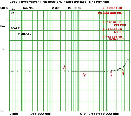
1 PI & T Attenuators Version This document is for printed circuit board version 0.0a for both the PI and T attenuators. Overview & Features: The PI and T attenuators use 0805 resistors and for most values of attenuation will be accurate to within 0.25dB from DC to 3GHz. Note that resistor values above about 100 ohms will adversely impact high frequency response. For more detail see the attenuation graphs in the performance section. The resistor table below provides the resistor values, actual attenuation and expected return loss. In general the T attenuator configuration will provide better frequency response for high attenuator values because of the lower resistor values used. Attenuators are symmetrical and the input and output impedance is 50 ohms 1% resistor values are used and result in ideal accuracy typically better than 0.1dB Maximum input power is +23dBm Circuit Description 0805 size surface mount resistors R1 to R3 form the attenuator. The attenuation table below gives resistor values for different values of attenuation. J1 is a male SMA edge mount connector and J2 a female edge mount connector. The PCB is 20 x 10mm. Schematics & PCB PI Attenuator Schematics & PCB T Attenuator VE3CZ0 PI & T Attenuators 1/6
2 Resistor Table The following table shows the 1% resistor values used for various PI and T attenuators along with their ideal attenuation and return loss. Attenuator Resistor Values PI Attenuator T Attenuator Atten R1 R2 & R3 Atten RL R1 & R3 R2 Atten RL db Ohms Ohms db db Ohms Ohms db db Assembly Equipment you ll need Surface Mount Device (SMD) soldering kit o Temperature controlled soldering iron with fine tip. Insure the tip is grounded! o Small vise to hold the PCB o Liquid no clean solder flux o Two pair of SMD Tweezers o Isopropanol 99% o Cotton swabs Needle nose pliers Heat gun for heat shrink Scissors VE3CZ0 PI & T Attenuators 2/6
3 Before You Begin Check the contents of the kit to make sure that none of the parts are missing. Print out this document to help locate components on the printed circuit board. Assembly Tips 1. Use two pair of tweezers, one for pulling up the hold down tape on the parts sheet and opening the SMD part carrier, and the other for mounting components on the PCB. This prevents the tape glue residue from getting on the tweezers used for SMD mounting work. 2. If adhesive does get onto the tweezers tips, parts will stick to them. If this happens wet a cotton swab with isopropyl alcohol. Spread the tweezers tips to clamp around the swab and draw them across the swab to clean the tips. 3. Orient all resistors that have values marked on them in the same direction so that they can more easily be read and identified after installation. Use the same orientation as is used on the PCB silk screen. 4. As you go through each assembly section check off components in the square box beside the component identifier as you install devices. Assembly 1. Install all top side PCB components In the next steps the attenuator resistors are soldered to the PCB. Typically there is a PCB silk screen printed on the green solder mask that indicates the position of the resistors. However in this case the solder mask alters the impedance of the coplanar waveguide tracks so both the solder mask and the silk screen have been removed over the coplanar waveguide. This unfortunately also removes the aids that help position the resistors. Look at the PCB layouts above. Note the locations where a resistor is to be soldered to the ground plane. In these areas additional solder mask has been removed so that the solder area juts out further into the ground plane. The resistors to ground should be placed in the center of these areas. R1 Per table of Attenuator Resistor Values R2 Per table of Attenuator Resistor Values R3 Per table of Attenuator Resistor Values In the next step SMA PCB edge mount connectors are installed. Fit each connector into the PCB and align it so that the center pin is in the middle of the PCB s coplanar waveguide track. Also make sure the SMA connector is square to the end of the PCB. Solder the center conductor first then the two top ground plane connectors. Then turn the PCB over and solder the bottom side ground plane leads. J1 SMA edge mount male J2 SMA edge mount female Functional Verification Test 1 A quick DC test will confirm that the attenuator resistor values are correct and reasonably soldered. Measure the DC resistance from the SMA center pin to ground on both ends of the attenuator. The value measured will be the same at both ends of the attenuator. For the T attenuator the resistance must be the sum of the input and shunt resistors (R1+R2 or R3+R2). For the PI attenuator the resistance will be the input shunt resistor in parallel with the sum of the series resistor and output shunt resistor (R2//(R1+R3) or R3//(R1+R2). A spreadsheet Attenuator DC Resistance Calculator can be used to provide a value for the resistance from the SMA center pin to ground by entering attenuator resistor values. Physical Assembly Use the scissors to cut the attenuation value out of the label that held the SMA parts. Cut along the cell guidelines and place the attenuation value on the PCB top side nesting it between the SMA connectors. Place the heat shrink over the assembly then apply heat to VE3CZ0 PI & T Attenuators 3/6


4 the heat shrink. Carefully manage the position of the heat shrink as the heat gun may blow it about. You may want to hold the heat shrink in place by using tweezers to hold it against the PCB. It should be positioned so that it will not interfere with the male SMA nut, and stretches out over the female connector covering a portion of the threads. Electrical Performance The following graphs show typical attenuation versus frequency performance for the 3 and 10 db PI and T attenuators. Note that the vertical scale is 0.5dB per division for the 3db attenuators and 2dB per division for the 10dB attenuators. VE3CZ0 PI & T Attenuators 4/6


5 VE3CZ0 PI & T Attenuators 5/6
6 VE3CZ0 PI & T Attenuators 6/6
DEM ABPM KIT All Band Power Meter Assembly Notes and Pictures
 DEM ABPM KIT All Band Power Meter Assembly Notes and Pictures Paul Wade W1GHZ w1ghz@arrl.net Down East Microwave has kindly agreed to make kits available for my All Band Power Meter (Note: I receive no
PSU for LawMate 500mW Transmitters. Assembly and Operation Manual
 PSU for LawMate 500mW Transmitters Assembly and Operation Manual Introduction Thank you for purchasing LawMate 500mW Power Supply. This power supply was specifically designed for the 500mW LawMate transmitter
PSU V2 for LawMate 500mW Transmitters. Assembly and Operation Manual
 PSU V2 for LawMate 500mW Transmitters Assembly and Operation Manual Introduction Thank you for purchasing the V2 LawMate 500mW Power Supply. This power supply was specifically designed for the 500mW LawMate
How to solder SMD component on Awesome PCB or any other kind of PCB.
 How to solder SMD component on Awesome PCB or any other kind of PCB. Step by step tutorial, with no steps to skip. Step 1 - What do we need? Step 2 - Fixing PCB Step 3 - Preparing for soldering Step 4
SMD-Dummy-BNC Assembly Instructions
 This small QRP sized dummyload was designed as a learning tool for SMD soldering by using larger 2512 resistors with only 1 small SOT-23 diode. The 50 ohm load will operate from 500KHz to 30MHz with an
Pacific Antenna Low Pass Filter Kit
 Pacific Antenna Low Pass Filter Kit Description Many basic transmitter and/or transceiver designs have minimal filtering on their output and frequently have significant harmonic content in their signals.
LPF-9B Nine band low pass filter module kit ( meters)
") LPF-9B Nine band low pass filter module kit (80-60-40-30-20-17-15-12-10 meters) Assembly manual Last update: March 1, 2018 ea3gcy@gmail.com Most recent updates and news at: www.ea3gcy.com Thanks for constructing
LPF-9B Nine band low pass filter module kit (80-60-40-30-20-17-15-12-10 meters) Assembly manual Last update: March 1, 2018 ea3gcy@gmail.com Most recent updates and news at: www.ea3gcy.com Thanks for constructing
LP-200 Dummy Load / Wattmeter
 LP-200 Dummy Load / Wattmeter Enclosure Retrofit Assembly Instructions March 2009 TelePost Incorporated LP-200 is a trademark of TelePost Inc. Material in this document copyrighted 2009 TelePost Inc. 1
Instructions for Lighting an S Scale Caboose
 Instructions for Lighting an S Scale Caboose The S Scale Caboose lighting kit is adaptable for most caboose models of rolling stock including American Flyer (TM) and contains the same components as found
Yana Dongles Tom Berger K1TRB (c)2016 v171227
2016 v171227") Yana Dongles Tom Berger K1TRB (c)2016 v171227 These notes elaborate some items described in the Build notes, and add some more dongles enhancing Yana. Every effort has been exerted to save on the cost
Yana Dongles Tom Berger K1TRB (c)2016 v171227 These notes elaborate some items described in the Build notes, and add some more dongles enhancing Yana. Every effort has been exerted to save on the cost
GORE Aerospace Ethernet Cables
 Termination Instructions The following procedures are based on Gore s best practices for terminating GORE Aerospace with the Amphenol Oval Contact System (OCS) for both plug and receptacle versions. These
TKEY-1. CW touch key. (no electromechanical contacts) Assembly manual. Last update: May 1,
 Assembly manual. Last update: May 1,") TKEY-1 CW touch key (no electromechanical contacts) Assembly manual Last update: May 1, 2016 ea3gcy@gmail.com Updates and news at: www.qsl.net/ea3gcy Thanks for constructing the TKEY-1A CW touch key Have
TKEY-1 CW touch key (no electromechanical contacts) Assembly manual Last update: May 1, 2016 ea3gcy@gmail.com Updates and news at: www.qsl.net/ea3gcy Thanks for constructing the TKEY-1A CW touch key Have
ELECTRICAL CONNECTIONS
 ELECTRICAL CONNECTIONS Lesson 13 EET 150 Electrical Connections Learning Objectives In this lesson you will: see different methods of making electrical connections. learn a procedure for making soldered
BP-1A. Band-Pass variable filter continuous tuning from 3 to 30MHz. For analogue or software-defined receivers (SDR) Assembly manual
 Assembly manual") BP-1A Band-Pass variable filter continuous tuning from 3 to 30MHz. For analogue or software-defined receivers (SDR) Assembly manual Last updated: December 1, 2017 ea3gcy@gmail.com Updates and news at:
BP-1A Band-Pass variable filter continuous tuning from 3 to 30MHz. For analogue or software-defined receivers (SDR) Assembly manual Last updated: December 1, 2017 ea3gcy@gmail.com Updates and news at:
Assembly Instructions for the 1.5 Watt Amplifier Kit
 Assembly Instructions for the 1.5 Watt Amplifier Kit 1.) All of the small parts are attached to a sheet of paper indicating both their value and id. 2.) Leave the parts affixed to the paper until you are
Technical Specifications:
 Technical Specifications: Print Method: Print Speed: Duplex Speed: First page out: Resolution: Duty Cycle: Memory: Laser Color up to 5ppm Monochrome up to 21ppm Color up to 5ipm Monochrome up to 9.5ipm
Overview of Soldering Assessment Programs
 Overview of Soldering Assessment Programs 1 Objectives Provide a mechanism or program to evaluate the soldering and assembly skills of operators or applicants 2 Goals Provide Customer with the: Ability
Field Installed Connectors for TraceTek 7000-HUV Bulk Cable Installation Instructions
 TraceTek TT-7000-HUV-CK-MC-M/F Field Installed Connectors for TraceTek 7000-HUV Bulk Cable Installation Instructions Description These instructions describe field connecting of TT7000-HUV Bulk Sensing
EA6500 Antenna Installation Instructions:
 Thank you for purchasing the 6 Antenna Mod Kit for your Linksys router. First we will show you how to install the antennas for your router. Next we will teach you how to setup the DD-WRT firmware which
2 Recommended Tools / Supplies
 Bias Scout TM Kit Assembly Manual Version 3.1 25 March 2015 1 Inventory of Parts 1 ea octal socket 1 ea octal base, brown (1 3/16" dia x 7/8" high) 1 ea 1.0 / 1W metal oxide, flame proof resistor 1 ea
Construction Guide European Version
 Construction Guide European Version PCB This section describes how to build up the DRO-350 printed circuit board (PCB). The bare PCB is available for purchase on the order page. Static Protection Bare
Design and Matching of a 60-GHz Printed Antenna
 Application Example Design and Matching of a 60-GHz Printed Antenna Using NI AWR Software and AWR Connected for Optenni Figure 1: Patch antenna performance. Impedance matching of high-frequency components
The ability to make basic voltage and resistance measurements using a digital multimeter
 Congratulations on your purchase of a new OneShot chassis! The PC01 OneShot combines a rugged enclosure, power supply, and discrete instrument DI in a compact 1/4U package. A few minutes of assembly are
Assembly and User Guide
 Assembly and User Guide AtariPunkr is an adjustable stepped tone generator. AtariPunkr provides hours of fun everyone! Powered by: 9V Battery Outputs: Mylar Speaker (Included) Stereo Output (3.5mm Jack)
Application Note 5525
 Using the Wafer Scale Packaged Detector in 2 to 6 GHz Applications Application Note 5525 Introduction The is a broadband directional coupler with integrated temperature compensated detector designed for
10W Class D Stereo Amplifier Kit
 1 Total Solder Joints: 70 Difficulty Level : beginner expert 10W Class D Stereo Amplifier Kit PARADIGM Technologies (UK) Ltd Electronic Kits and Modules K1420 High power multipurpose audio amplifier Specifications
Assembly Instructions for the FRB FET FM 70 Watt Amp
 Assembly Instructions for the FRB FET FM 70 Watt Amp 1.) Orient the circuit board with the diagram 2.) Use a narrow chisel tip 25-30 watt soldering iron for assembly 3.) All the small parts are taped onto
The Design of A 125W L-Band GaN Power Amplifier
 Sheet Code RFi0613 White Paper The Design of A 125W L-Band GaN Power Amplifier This paper describes the design and evaluation of a single stage 125W L-Band GaN Power Amplifier using a low-cost packaged
Coaxial TRL Calibration Kits for Network Analyzers up to 40 GHz
 Focus Microwaves Inc. 277 Lakeshore Road Pointe-Claire, Quebec H9S-4L2, Canada Tel 514-630-6067 Fax 514-630-7466 Product Note No 2 Coaxial TRL Calibration Kits for Network Analyzers up to 40 GHz This note
Cricket 80a Assembly Manual v Copyright David Cripe NM0S The 4 State QRP Group
 Cricket 80a Assembly Manual v. 1.0 Copyright 2017 David Cripe NM0S The 4 State QRP Group Introduction Thank you for purchasing a CRICKET 80a Transceiver. We hope you will enjoy building it and find it
SSRP LTC1746 Assembly Manual V0.1 Check the most recent version
 SSRP LTC1746 Assembly Manual V0.1 Check the most recent version http://oscar.dcarr.org/ssrp/hardware/ltc1746/ltc1746.php Introduction This manual details the general assembly process for the SSRP LTC1746
AR.Drone 2 - Main Board External Antenna Modification Procedure. Document Number: EAM Check back for updates.
 Document Number: EAM-20130303-2 Check back for updates. 3/22/2013 NOTE: Along with this mod procedure, you will also need to: 1. Remove the Main Board. Refer to the Main Board Removal Procedure 2. Adapt
upad Proto Base Assembly Guide v2.0
 upad Proto Base Assembly Guide v2.0 Last Updated September 1, 2015 Table of Contents Preface... 3 Introduction... 3 Required Tools... 3 Flux Pen... 3 Soldering Iron... 3 Solder... 3 Diagonal Cutters...
WLAN/BT/Zigbee/Wi-Fi/Embedded Stamp Metal Antenna
 APPLICATION NOTES AN-WF-0146-20180522 2.4/4.9/5.2/5.8 GHz (802.11 a/b/g/n/c + Japan) Applications: Embedded Design Handheld Wireless Headsets Tablets Gateway Access Point Telematics Tracking M2M Healthcare
Weii 2.4 GHz Ceramic Antenna Part no: SRCW004 ceriiant Product Specification
 Weii 2.4 GHz Ceramic Antenna Part no: SRCW004 ceriiant Product Specification 1. Features: 2.4GHz applications Bluetooth, WiFi, Zigbee, ISM. Ultra small ceramic chip solution. High Efficiency. SMD mounted.
10W Class D Ultra Stereo Amplifier Kit
 1 Total Solder Joints: 70 Difficulty Level : beginner expert PARADIGM Technologies (UK) Ltd Electronic Kits and Modules 10W Class D Ultra Stereo Amplifier Kit K1421 High power / quality audio amplifier
Xkitz.com XLO-5CP Control Panel for Five Channel Color Light Organ
 Xkitz.com XLO-5CP Control Panel for Five Channel Color Light Organ Rev 1.15 An Optional accessory for the Xkitz XLO-5 or XLO-5DC 5 Channel Color Light Organs Introduction This kit contains all the electronics
PAT-4 POWER SUPPLY ASSEMBLY MANUAL Rev B Version
 PAT-4 POWER SUPPLY ASSEMBLY MANUAL Rev B Version 2013 AkitikA, LLC All rights reserved Revision Bp01 November 3, 2013 Page 1 of 16 Table of Contents Table of Contents... 2 Table of Figures... 2 Section
Solder Technique Studio Soldering Iron Fundamentals for the Mixed Media Artist
 Solder Technique Studio Soldering Iron Fundamentals for the Mixed Media Artist Giuseppina Josie Cirincione north light books CreateMixedMedia.com Cincinnati, Ohio Materials Basic soldering tool kit Solder,
PAGE 1/6 ISSUE Jul SERIES Micro-SPDT PART NUMBER R516 XXX 10X R 516 _ 1 0 _
 PAGE 1/6 ISSUE Jul-24-2017 SERIES Micro-SPDT PART NUMBER R516 XXX 10X R516 series: the RAMSES concept merges with the SLIM LINE technology, breaking up the frequency limits of SMT switches : - FULL SMT
FM Wireless Microphone Kit Instructions for Assembly Page 1 of 5
 Instructions for Assembly Page 1 of 5 1. Find Resistor R1. Remove any tape that may be attached to the leads. Bend the leads as needed to insert Resistor R1 into the printed circuit board in the holes
Spectrian 2304 MHz SSPA. Garry C. Hess, K3SIW June 11, 2004
 Spectrian 2304 MHz SSPA Garry C. Hess, K3SIW June 11, 2004 A solid-state power amplifier (SSPA) manufactured by Spectrian can produce on the order of 200 W linear output 1 at 2304 MHz with little modification.
PAGE 1/6 ISSUE SERIES Micro-SPDT PART NUMBER R516 XXX 10X. (All dimensions are in mm [inches]) R 516 _ 1 0 _
![PAGE 1/6 ISSUE SERIES Micro-SPDT PART NUMBER R516 XXX 10X. (All dimensions are in mm [inches]) R 516 _ 1 0 _](/thumbs/96/127769340.jpg "PAGE 1/6 ISSUE SERIES Micro-SPDT PART NUMBER R516 XXX 10X. (All dimensions are in mm [inches]) R 516 _ 1 0 _") PAGE 1/6 ISSUE 15-10-18 SERIES Micro-SPDT PART NUMBER R516 XXX 10X R516 series: the RAMSES concept merges with the SLIM LINE technology, breaking up the frequency limits of SMT switches : - FULL SMT TECHNOLOGY
PAGE 1/6 ISSUE 15-10-18 SERIES Micro-SPDT PART NUMBER R516 XXX 10X R516 series: the RAMSES concept merges with the SLIM LINE technology, breaking up the frequency limits of SMT switches : - FULL SMT TECHNOLOGY
LED Field Strength Indicator Kit
 LED Field Strength Indicator Kit Description The Field Strength Indicator kit from Qrpkits.com provides a visual way to monitor RF fields through the brightness of an LED. It will respond to RF fields
Atlas GenSet Tsunami Digital Sound Decoder Installation Notes
 Atlas GenSet Tsunami Digital Sound Decoder Installation Notes Overview This application note describes how to install a TSU-AT1000 digital sound decoder into an Atlas HO GenSet. Skill Level 2: The entire
APPLICATION NOTE FOR PA.710A ANTENNA INTEGRATION
 APPLICATION NOTE FOR PA.710A ANTENNA INTEGRATION APN-11-8-001/B Page 1 of 22 1. TABLE OF CONTENTS 1. TABLE OF CONTENTS... 2 2. BASICS... 4 3. APPLICATIONS... 5 4. IMPEDANCE... 5 5. BANDWIDTH... 5 6. GAIN...
Bushwacker Jeep Flat Style Fender Flares Front Pair
 Bushwacker Jeep Flat Style Fender Flares Front Pair Note: These instructions involve cutting parts of your vehicle. Please read all instructions prior to starting. Installation Time: 3-4 Hours Tools Required:
Tek-Bot Remote Control Transmitter Board Construction
 Tek-Bot Remote Control Transmitter Board Construction Purpose This tutorial illustrates the procedure for construction of the Transmitter board for the Tek-bot. A Guide to Soldering Many of you have soldered
Pacific Antenna 20 and 40M Lightweight Dipole Kit
 Pacific Antenna 20 and 40M Lightweight Dipole Kit Diagram showing configuration and approximate lengths 8 3 16 9 16 9 8 3 Description The Pacific Antenna lightweight dual band, trap dipole kit provides
The Switched Longwire Tuner SLT
 The Switched Longwire Tuner SLT Thank you for purchasing the SLT kit from Hendricks QRP Kits. This kit is a very high quality kit that you will find easy to build, yet when you finish, you will have a
WARNING! ETCHED PARTS CONTAINED IN THIS KIT HAVE SHARP POINTS, EDGES AND CORNERS.
 MPD18 chassis build instructions K A (see below for details) J I G H L C D F E B M Parts list: Ident Quantity A Etched Nickel/Silver fret 1 B Wheel sets 2 C Worms 2 D Worm gears 2 E Shaft adapters 2 F
Description RF Explorer RFEAH-25 1 is a 25mm diameter, high performance near field H-Loop antenna.
 Description RF Explorer RFEAH-25 1 is a 25mm diameter, high performance near field H-Loop antenna. RFEAH-25 is a very sensitive, compact and easy to use H-loop near field antenna. The low-loss design exhibits
The Useless Machine. DIY Soldering Edition. Instruction Guide v0004
 The Useless Machine DIY Soldering Edition Instruction Guide v0004 TM For the best outcome, follow each step in order. We recommend reading this guide entirely before you get started. Tools required: Soldering
Repairing your Porsche 928 Central Warning System (CWS) controller
 controller") Repairing your Porsche 928 Central Warning System (CWS) controller Disclaimer: This procedure is for a 1984 Porsche 928 S controller. Overview: Under the left foot pedal (dead pedal) of the Porsche 928
Repairing your Porsche 928 Central Warning System (CWS) controller Disclaimer: This procedure is for a 1984 Porsche 928 S controller. Overview: Under the left foot pedal (dead pedal) of the Porsche 928
VOLUME AND TONE CONTROL - PREAMPLIFIER K8084
 VOLUME AND TONE CONTROL - PREAMPLIFIER K8084 When using one of our amplifiers (big or small), you always need a volume control and preferably also a tone control H8084IP-1 Features & specifications When
Bill of Materials: PWM Stepper Motor Driver PART NO
 PWM Stepper Motor Driver PART NO. 2183816 Control a stepper motor using this circuit and a servo PWM signal from an R/C controller, arduino, or microcontroller. Onboard circuitry limits winding current,
Anritsu Microwave K Connector
 Instruction Sheets Anritsu Microwave K Connector K101F-R K101M-R K101M-085-R K102F-R K102M-R K103F-R K103M-R K104F-R K104M-R K110-1-R or K110-3-R K110-2-R 01-104 01-108 Anritsu Company 490 Jarvis Drive
Music Thing Modular SimpleEQ Construction Guide (1206 version)
") Music Thing Modular SimpleEQ Construction Guide (1206 version) Page 1 Useful Links The latest version of this doc and BOM can always be found at http://thonk.co.uk/documents/eq/ A build thread on the Muffwiggler
Music Thing Modular SimpleEQ Construction Guide (1206 version) Page 1 Useful Links The latest version of this doc and BOM can always be found at http://thonk.co.uk/documents/eq/ A build thread on the Muffwiggler
ECE 145A/218A, Lab Project #1a: passive Component Test.
 ECE 145A/218A, Lab Project #1a: passive Component Test. September 28, 2017 OVERVIEW... 2 GOALS:... 2 PRECAUTIONS TO AVOID INSTRUMENT DAMAGE... 2 SAFETY PRECAUTIONS... 2 READING:... 3 NETWORK ANALYZER CALIBRATION...
C-Note Bookshelf Speaker Kit
 C-Note Bookshelf Speaker Kit Thank you for purchasing the C-Note bookshelf speaker kit. This speaker kit was precision cut using CNC machinery for the best possible fit and finish. With a little time and
Line Following Circuit Board Wiring Guide
 Line Following Circuit Board Wiring Guide Soldering the Analog Optosensors 1. Obtain a line following printed circuit board from the store as well as three analog optosensors (w/6 resistors). 2. Remove
Cheeper Assembly instruction
 1. Equipment, materials and tools for assembly.......2 2. Assembly.....3 3. Setting of the model.....11 1. Equipment, materials and tools for assembly 1 Wing; 2 Fuselage; 3 Stabilizer; 4 Fin; 5 Dowel for
Instructions to Convert a 4-foot Florescent Fixture to LEDs Using a SS 25W Power Supply and a 4 LED strip 30Dec15
 Instructions to Convert a 4-foot Florescent Fixture to LEDs Using a SS 25W Power Supply and a 4 LED strip 30Dec15 Thank you for purchasing the Shoplight Solutions 4-ft conversion kit. This is a companion
Custom Front Panel Upgrade Instructions
 Custom Front Panel Upgrade Instructions Here are the directions for upgrading your SP-II to an SP-IIB, with a custom blackanodized front panel and engraved lettering. There are only forty SP-IIB s in existence
A Precision 2000 Mixed Media Project
 Día de los Muertos (Day of the Dead) Panel A Precision 2000 Mixed Media Project PROJECT TITLE: Día de los Muertos (Day of the Dead) Panel DESIGNED BY: Andy Spencer SKILL LEVEL: (Adult 1-5: 1 being the
Microwave Metrology -ECE 684 Spring Lab Exercise T: TRL Calibration and Probe-Based Measurement
 ab Exercise T: TR Calibration and Probe-Based Measurement In this project, you will measure the full phase and magnitude S parameters of several surface mounted components. You will then develop circuit
Bachmann GP7 Tsunami Digital Sound Decoder Installation Notes
 Bachmann GP7 Tsunami Digital Sound Decoder Installation Notes Overview This application note describes how to install a TSU-AT1000 digital sound decoder into a Bachmann HO GP7. Skill Level 3: One to three
S Powered by +5V Supply. S Input Configurable for Electrical and Optical Evaluation
 19-4980; Rev 0; 9/09 MAX3806 Evaluation Kit General Description The MAX3806 evaluation kit (EV kit) is an assembled and tested demonstration board that simplifies evaluation of the MAX3806 receiver for
Tuna Tunah. Switched Inductor Antenna Tuner. Builder's Guide by Kevin Gilot NZ1I & Rex Harper W1REX. version 1.2
 Tuna Tunah Switched Inductor Antenna Tuner Builder's Guide by Kevin Gilot NZ1I & Rex Harper W1REX version 1.2 Tuna Tunah List of Materials Qty Description PCB Location ( ) 1-.22uH Inductor (Red-Red-Silver).22
High Voltage Differential Probe
 High Voltage Differential Probe Main characteristics: Jacques Audet VE2AZX jacaudet [at] videotron.ca - Based on the AD8479, Very High Common-Mode Voltage Precision Difference Amplifier, which includes
ScaleRCHelis.com V Light Controller Kit
 Thank you for purchasing the ScaleRCHelis.com V1.1 450 Light Controller Kit. This is something you can build in under a hour with some simple soldering equipment. Your kit will include all the parts necessary
APPLICATION NOTE FOR PA.700A ANTENNA INTEGRATION
 APPLICATION NOTE FOR PA.700A ANTENNA INTEGRATION VERSION A Your Global Source for RF, Wireless & Energy Technologies www.richardsonrfpd.com 800.737.6937 630.208.2700 APN-11-8-001/A 14-July-11 Page 1 of
Challenges and Solutions for Removing Fixture Effects in Multi-port Measurements
 DesignCon 2008 Challenges and Solutions for Removing Fixture Effects in Multi-port Measurements Robert Schaefer, Agilent Technologies schaefer-public@agilent.com Abstract As data rates continue to rise
Agilent Accessories Selection Guide For Impedance Measurements. December 2008
 Agilent Accessories Selection Guide For Impedance Measurements December 2008 Table of Contents Introduction 1 1. What are Agilent Accessories? 1 2. Types of Accessories 1 3. The Benefits of Agilent Accessories
RF Layout Application Note
 RF Layout Application Note Rev. RF_Layout_Application_Note_2.0 Date: 2014-10-16 www.quectel.com Our aim is to provide customers with timely and comprehensive service. For any assistance, please contact
Kato N-Scale E8 Tsunami Digital Sound Decoder Installation Notes
 Kato N-Scale E8 Tsunami Digital Sound Decoder Installation Notes Overview This application note describes how to install a TSU-750 digital sound decoder into a Kato N-scale E8. Skill Level 4: The entire
Manual Version July 2007
 Manual Version 1.2 - July 2007 Page 1 Table of Contents Section1: M3 Phono Board Build...3 Phono Board Parts List...3 Preparation...4 Fitting the Valve Bases...6 Installing the Resistors...7 Starting the
HMC274QS16 / 274QS16E. Features OBSOLETE. = +25 C, Vdd = +3V to +5V & Vctl = 0/Vdd. Parameter Frequency Min. Typical Max. Units
 Typical Applications Functional Diagram v1. The HMC274QS16 / HMC274QS16E is ideal for: Cellular/PCS/3G Infrastructure 2.4 GHz ISM Radios Wireless Data HMC274QS16 / 274QS16E 1 LSB GaAs IC -BIT DIGITAL ATTENUATOR,.7-2.7
QUAVERATO MIDI MOD. Assembly Instructions
 QUAVERATO MIDI MOD Assembly Instructions 110118 QUAVERATO MIDI MOD Assembly Instructions WHAT YOU WILL NEED...3 WHAT S IN THE BOX...4 POPULATING THE PRINTED CIRCUIT BOARD...7 THE CHASSIS...13 UPDATING
EXTENDING THE LINES. by Annis Clapp BLOCK OF THE WEEK
 EXTENDING THE LINES A Fresh Approach to Foundation Paper Piecing by Annis Clapp Week 1 Week Week Week Week BLOCK OF THE WEEK 1 - General Instructions, Easy Log Cabin Introduction Foundation paper piecing
KIT CONTENTS. Round power strip multipurpose flex box 5 yard long wire extension cord Socket. Table Lamp with Magnifier- 1No DMM
 KIT CONTENTS Kit Bag Extension Box Round power strip multipurpose flex box 5 yard long wire extension cord Socket Table Lamp with Magnifier- 1No DMM Used to inspect the board and connections while soldering
BrewsBySmith.com STC DIY Kit
 BrewsBySmith.com STC-1000 + DIY Kit Contact Information: Greg Smith www.brewsbysmith.com greg@boostbysmith.com I. Hardware Included: STC-1000 flashed with latest software (v1.06 currently) (if purchased)
V-TUNE. Variable capacitance mini-circuit with Varactor diode and potentiometer control. Assembly manual. Last updated: July 15, 2017
 V-TUNE Variable capacitance mini-circuit with Varactor diode and potentiometer control Assembly manual Last updated: July 15, 2017 ea3gcy@gmail.com Updates and news at: www.ea3gcy.com Thanks for building
Application Note. Athearn RTR AC4400CW Tsunami Digital Sound Decoder Installation Notes
 Application Note Overview This application note describes how to install a TSU-AT1000 Digital Sound Decoder into an HO Athearn Ready To Roll AC4400CW. Skill Level 2: The entire installation can be completed
8x8 Red Blue Green Yellow Audio Indicator
 8x8 Red Blue Green Yellow Audio Indicator 1. Introduce. 1>. Working voltage: 5V. 2>. PCB size: 75*45mm. 3>. There are four fixed mounting holes on PCB. 4>. It is no need for filter circuit. It can driver
Installation tutorial for Console Customs Xbox Mode Dual Button (RFX-5B) Rapid fire Microchip for all Wired and Wireless controllers
 Rapid fire Microchip for all Wired and Wireless controllers") Installation tutorial for Console Customs Xbox 360 5-Mode Dual Button (RFX-5B) Rapid fire Microchip for all Wired and Wireless controllers This tutorial is designed to aid you in installation of a console
Installation tutorial for Console Customs Xbox 360 5-Mode Dual Button (RFX-5B) Rapid fire Microchip for all Wired and Wireless controllers This tutorial is designed to aid you in installation of a console
Instructions to Convert a 4-foot Florescent Fixture to LEDs Using 60W Power Supply Using 2 or 3 strips 30Dec15
 Instructions to Convert a 4-foot Florescent Fixture to LEDs Using 60W Power Supply Using 2 or 3 strips 30Dec15 Thank you for purchasing the Shoplight Solutions 4-ft conversion kit. This is a companion
APPLICATION NOTE FOR PA.710.A ANTENNA INTEGRATION
 APPLICATION NOTE FOR PA.710.A ANTENNA INTEGRATION APN-13-8-005/B/NB Page 1 of 17 1. TABLE OF CONTENTS 1. TABLE OF CONTENTS... 2 2. BASICS... 3 3. APPLICATIONS... 4 4. IMPEDANCE... 4 5. BANDWIDTH... 4 6.
Assembly Instructions
 Assembly Instructions For the SSQ-2F 3.1 MHz Rife Controller Board Kit v1.41 Manual v1.00 2012 by Ralph Hartwell Spectrotek Services GENERAL ASSEMBLY INSTRUCTIONS Arrange for a clean work surface with
Stall warner - retrofit installation - XS
 Stall warner - retrofit installation - XS Part 1 - retrofit to aircraft with XS wings Mark a point on the starboard wing root rib half way between the forward lift pin and the front of the spar, and half
Soldering Techniques NIAGARA COLLEGE TECHNOLOGY DEPT.
 Soldering Techniques NIAGARA COLLEGE TECHNOLOGY DEPT. Soldering 101 Soldering is the process of joining two metals together to form an electrically ll and mechanically secure bond using heat and a third
Mini Dart Assembly instruction
 Assembly instruction 1. Equipment, materials and tools for assembly.......2 2. Assembly.....3 3. Setting of the model.....11 1. Equipment, materials and tools for assembly 1 Wing; 2 Fuselage; 3 Stabilizer;
Pacific Antenna Easy SWR Indicator Kit
 Pacific Antenna Easy SWR Indicator Kit Description Monitoring the match of an antenna to your transmitter or adjusting an antenna tuner for best match requires an indicator of the reflected power as an
1. Initial Precautions 2. Technical Precautions and Suggestions 3. General Information and Cure Stages 4. Understanding and Controlling Cure Time
 How to apply Arctic Silver Premium Thermal Adhesive 1. Initial Precautions 2. Technical Precautions and Suggestions 3. General Information and Cure Stages 4. Understanding and Controlling Cure Time 5.
Motorola Droid Turbo Chargerport
 Motorola Droid Turbo Chargerport Replacement The fine engineers at Motorola have outdone themselves once again, this time they went way over the top. I decided to create a guide as some of the techniques
Pacific Antenna - Easy TR Switch
 Pacific Antenna - Easy TR Switch Kit Description The Easy TR Switch is an RF sensing switch that can be used to switch an antenna between a receiver and transmitter. It also has a second switched pair
PA1.3-2 Linear Amplifier Mini-kit
 PA1.3-2 Linear Amplifier Mini-kit Construction and operating notes Version 1.1 January 2001 (Version 2 PCB shown the PCB has been up-issued to version 3) 1 Introduction The PA1.3-2 is a low power amplifier
SPECIFICATION. Product Name : Dual-Band 2.4/5GHz Wi-Fi Ceramic SMD Antenna
 SPECIFICATION Part No. : SDWA.01 Product Name : Dual-Band 2.4/5GHz Wi-Fi Ceramic SMD Antenna Features : High Efficiency/ High Peak Gain 2400 MHz to 2483 MHz - Peak Gain 4.4 dbi max 5180 MHz to 5825 MHz
Elektor Construction Guide TAPIR
 Elektor Construction Guide TAPIR The TAPIR is a three-dimensional assembly. To ensure good access to all soldering points, we recommend assembling the kit exactly according to the described sequence. 1
Modification of USB Sound Card for Asterisk app_rpt Use
 Modification of USB Sound Card for Asterisk app_rpt Use First off a huge thank you to Steve for providing the original notes on how to modify a USB sound card. (http://images.qrvc.com/usbfob.pdf) These