The 6LE8 One Tube Broadcaster
|
|
|
- Kerry Nichols
- 6 years ago
- Views:
Transcription

1 The 6LE8 One Tube Broadcaster
2 Introduction The purpose of this broadcaster is to transmit your favorite music to every AM radio in your home. The transmitting power is so low that it should not bother the neighbors. A common application would be to drive it from the speaker leads of your FM radio, which could then include playing your XM or Sirius to your AM sets, or just your favorite FM station. A steady decline in the selection of quality AM stations has created the need. Now your restored antique AM s can be playing the same music throughout your home simultaneously. The 6LE8 transmitter circuit is a modification of the 6888 tube transmitter originally designed by Norm Leal, a member of the Antique Radio Forums website (ARF). If you have questions about the transmitter, go to the Antique Radio Forums website and post a question in the homebrew section: (Antique Radios the collector s resource) Forums Homebrew New Topic
3 Parts The table at the following page lists the components that are needed to construct the transmitter. Some of the parts can be obtained from Radio Shack ( and part numbers are given for those items (even if the part is supplied with the kit). However, equivalent parts from any source will work. The exception is the 6LE8 tube, as the circuit has been tested with various different brands of tubes and found not to work satisfactorily with every brand. Generally the Sylvania's provide better performance than most of the other brands. Still there were some RCA's that performed very well. Newer GEs weren't bad but early ones were distorted, as was every made in Japan tube that was tested. Some of those non-working tubes can be made to work with custom modifications to the circuit and component values but it is not discussed here. A separate isolation transformer and filament transformer were used in the design so that the homebrewer could re-use either part in a future project if desired. Some parts such as TR1 and TR3 are not supplied in the kit. You can also use the parts list and the schematic to build the 6888 transmitter. You will need a different tube socket and the resistor R4 must be changed to 4.7 kohm (½ watt) and the value of R1 should be lowered to around 1 kohm (2 watts). You may also leave out the parts D5, C5 and R2 (and also the connection from the 6.3 V filament supply to D5) because the 6888 will work with or without them. The LED (D7) may be used even though it is not a part of the original 6888 circuit (it serves only as a power on indicator).
4 Symbol in schematic Qnty Description Notes (RS # means Radio Shack part number) R kω, 2 W resistor R Ω, ½ W resistor RS # R kω, ½ W resistor RS # R kω, ½ W resistor D1 D4 1 1A, 400 V full-wave bridge rectifier RS # D5 1 1N4001 diode RS # D volt, 1 watt zener diode RS # D7 1 light emitting diode (LED) RS # (any colour will work) C1, C µf safety capacitor (Y-type) any value between and 0.01 µf will work C3, C µf, 250 VDC electrolytic capacitor C µf, 10 VDC electrolytic capacitor RS # C6, C µf, 250 VDC film capacitor RS # C8, C pf, 250 VDC ceramic capacitor C µf, 250 VDC ceramic capacitor RS # C12 1 variable capacitor (trimmer) L µh coil TR V / V filament transformer RS # TR2 1 PC , 120 V / 2 x 6.3 V filament transformer TR3 1 audio transformer RS # OSC 1 1 MHz oscillator T1 1 6LE8 tube for example Sylvania brand F ma slow blow fuse (T) SW1 1 SPST switch RS # Miscellaneous: 9 pin miniature tube socket 1/8 mono audio jack RS # pin IC socket (for the oscillator) RS # fuse holder RS # perforated circuit board RS # binding post for the antenna wire RS # project enclosure RS # ft (3 meters) of wire for antenna 3-wire mains cord connecting wire machine screws and nuts Additional notes: The voltage ratings of the capacitors may be higher than the values given in the list but no lower. Same applies to the resistor wattages. There are no L1 and C10. They were part of an earlier version of the schematic and have been substituted by L2 and C12.
5
6 General Instructions THIS CIRCUIT USES DANGEROUSLY HIGH VOLTAGES INCLUDING MAINS (AC LINE) VOLTAGE WHICH CAN BE LETHAL SO IF YOU ARE NOT SURE WHAT YOU ARE DOING, DON T DO IT! For safety reasons it is best to use a three wire mains (AC) cord. The safety capacitors C1 and C2 are optional but they help to reduce unwanted interference from the mains (power line) which may cause hum. C1 and C2 must be special Y-type safety capacitors and cannot be substituted with any other type. TR1 in the schematic is a 120 VAC / 12.6 VAC centre tapped filament transformer such as the Radio Shack # but any other transformer with similar ratings can be used. If the used transformer has only one 6.3 VAC secondary winding it should be wired like this: The pin numbers of the TR2 are given in the schematic. You can make sure which pin is which using continuity tester: pins 1 and 2 should show continuity but pins 4 and 6 should not. The audio transformer (TR3) can be almost any audio transformer. The ratings are not critical. One suitable option is the Radio Shack audio
7 transformer (# ) which is also what is shown in the schematic. To avoid interference don t mount the audio input too close to the antenna. Before applying power for the first time make sure that everything is connected according to the schematic and that the electrolytic capacitor and diode polarities are correct. Peaking In order to get the maximum signal out of the transmitter, you will need to tune the tank circuit (capacitor + coil connected to the tube plate (anode)) into resonance with the oscillator frequency. An LC-circuit (L = coil, C = capacitor) will exhibit a certain resistance to AC-current flowing through it. When in resonance the resistance is at maximum. This transmitter uses a variable capacitor (C12) and a fixed coil (L2) as the tank circuit. It is also possible to use a variable coil and a fixed capacitor. One way to do the peaking is to monitor the cathode current of the tube. This will require disconnecting that particular circuit from ground (pin 3 6LE8) and hook an ammeter in between. Next adjust the variable capacitor and look for a "dip" in the current. An analog meter is the best for this, because the needle movement is so easy to observe but it can be done with digital meter also. Because the resistance is at maximum when correctly tuned you'll need to find a spot where the current is at minimum. The "peak" will be somewhat pronounced. The current will be somewhere in the range of 10 to 20 ma with this particular transmitter. The antenna is an important part of this and must be connected when peaking. The length of the antenna will affect the location of the "sweet spot" so use the antenna that you're going to use in the future with the transmitter. Another method is to monitor the B+ voltage at the second filter cap. Using this method, nothing needs to be disconnected. This time you're looking for maximum voltage because with minimum current the load to the power
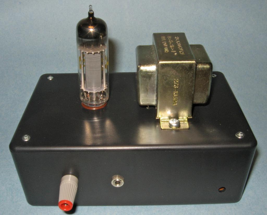
8 supply it at minimum hence the max voltage. Again an analog meter is easiest to observe, but a digital will be fine. The variation in B+ voltage will be in the range of millivolts (be careful since the B+ is over 100 volts!). It is important to use a non-metallic tool when doing the adjustments, as it can affect the result. The transmitter will work if not exactly tuned, but the performance will be a bit poorer. And if you change the oscillator to one that has a different frequency or change the length of the antenna you'll need to do the peaking again. The following pages show a component placing / wiring diagram and some pictures of the prototype 6LE8 transmitter which was assembled in a 6x4x2 project enclosure from Radio Shack. The picture in the cover is also from the same prototype. Some of the parts are different in the current kit. For example the prototype used Miller P-70-A adjustable antenna coil and a fixed 150 pf capacitor in the tank circuit. However, the pictures may still be useful for ideas.
9
10
11
N3ZI Kits General Coverage Receiver, Assembly & Operations Manual (For Jun 2011 PCB ) Version 3.33, Jan 2012
 Version 3.33, Jan 2012") N3ZI Kits General Coverage Receiver, Assembly & Operations Manual (For Jun 2011 PCB ) Version 3.33, Jan 2012 Thank you for purchasing my general coverage receiver kit. You can use the photo above as a
N3ZI Kits General Coverage Receiver, Assembly & Operations Manual (For Jun 2011 PCB ) Version 3.33, Jan 2012 Thank you for purchasing my general coverage receiver kit. You can use the photo above as a
Custom Integrated Circuit (MSM9520RS) Replacement Module
 Replacement Module") FT-101Z/ FT-107/ FT-707/ FT-901,902 (later version) DISPLAY COUNTER UNIT (PB-2086A) Custom Integrated Circuit (MSM9520RS) Replacement Module Assembly and Installation Manual (v1.3e) STEP-BY-STEP PROCEDURES
FT-101Z/ FT-107/ FT-707/ FT-901,902 (later version) DISPLAY COUNTER UNIT (PB-2086A) Custom Integrated Circuit (MSM9520RS) Replacement Module Assembly and Installation Manual (v1.3e) STEP-BY-STEP PROCEDURES
How The Transmitter Works
 Mike Bray, K8DDB Refer to the schematic of the transmitter on page 7 of the manual. The crystal-controlled oscillator, V generates a small amount of r.f. power which is used to drive the amplifier, V2.
The Electro-Magnetic Spectrum
 The Electro-Magnetic Spectrum Part Three In This Issue: All about Tubes How a diode rectifier works How a triode amplifier works How the mixer in your receiver works Dear Friends: For quite some time I
The ROSE 80 CW Transceiver (Part 1 of 3)
") Build a 5 watt, 80 meter QRP CW Transceiver!!! Page 1 of 10 The ROSE 80 CW Transceiver (Part 1 of 3) Build a 5 watt, 80 meter QRP CW Transceiver!!! (Designed by N1HFX) A great deal of interest has been
Build a 5 watt, 80 meter QRP CW Transceiver!!! Page 1 of 10 The ROSE 80 CW Transceiver (Part 1 of 3) Build a 5 watt, 80 meter QRP CW Transceiver!!! (Designed by N1HFX) A great deal of interest has been
EE12: Laboratory Project (Part-2) AM Transmitter
 AM Transmitter") EE12: Laboratory Project (Part-2) AM Transmitter ECE Department, Tufts University Spring 2008 1 Objective This laboratory exercise is the second part of the EE12 project of building an AM transmitter in
EE12: Laboratory Project (Part-2) AM Transmitter ECE Department, Tufts University Spring 2008 1 Objective This laboratory exercise is the second part of the EE12 project of building an AM transmitter in
TS500 Assembly guide. Soldering. TS500 Assembly guide Main PCB 1. Diodes. Document revision 1.2 Last modification : 17/12/16
 TS500 Assembly guide Safety warning The kits are main powered and use potentially lethal voltages. Under no circumstance should someone undertake the realisation of a kit unless he has full knowledge about
The Tellun Corporation. TLN-861 Dunsel. User Guide, Rev Scott Juskiw The Tellun Corporation
 The Tellun Corporation TLN-861 Dunsel User Guide, Rev. 1.0 Scott Juskiw The Tellun Corporation scott@tellun.com TLN-861 User Guide Revision 1.0 August 31, 2006 1. Introduction The TLN-861 Dunsel is a collection
A 75-Watt Transmitter for 3 Bands Simplified Shielding and Filtering for TVI BY DONALD H. MIX, W1TS ARRL Handbook 1953 and QST, October 1951
 A 75-Watt Transmitter for 3 Bands Simplified Shielding and Filtering for TVI BY DONALD H. MIX, W1TS ARRL Handbook 1953 and QST, October 1951 The transmitter shown in the photographs is a 3-stage 75-watt
Step by Step Building PJ meter ARDF Receiver Kit. CRKITS.COM August 5, 2013
 Step by Step Building PJ-80 80-meter ARDF Receiver Kit CRKITS.COM August 5, 2013 What is ARDF? ARDF is the abbreviation of Amateur Radio Direction Finding, or so called Fox Hunting. If you are looking
XMT key output 4 8. Figure 1: Relay Assembly Schematic
 QSK T/R Switch for your Vintage Boat-Anchor Station Phil Salas AD5X Introduction As a CW operator, I enjoy full break-in operation with my Elecraft K3 transceiver. However, my Johnson Ranger/Drake 2B vintage
CX7 Troubleshooting Index
 CX7 Troubleshooting Index Modification S/1 Newsletter Guide Board Description A/TO A/TO MODE Intermod V1,12 P4.4 A11 Shut off one 35 MHz osc in receive, done sn 244 A/TO Spur V1,12 P1 Reduce A/TO spur,
Ear+ Purist HD. Ear+ HD II High Definition Stereo Headphone Amplifier
 Ear+ Purist HD Ear+ HD II High Definition Stereo Headphone Amplifier Users' Manual Rev Mar 8/19 Mapletree Audio Design R. R. 1, Seeley's Bay, Ontario, Canada, K0H 2N0 (613) 387-3830 www.mapletreeaudio.com
Assembly Manual V1R2B-Rev1.0D
 Assembly Manual V1R2B-Rev1.0D for 4 State QRP MagicBox - Solid State Transmit/Receive System Designed by: Jim Kortge, K8IQY Copyright 2009-2012 - All rights reserved This system is the result of some brainstorming
SUBELEMENT T6 Electrical components: semiconductors; circuit diagrams; component functions 4 Exam Questions - 4 Groups
 SUBELEMENT T6 Electrical components: semiconductors; circuit diagrams; component functions 4 Exam Questions - 4 Groups 1 T6A Electrical components: fixed and variable resistors; capacitors and inductors;
SERVICE MANUAL. Subwoofer Amplifier Model: SW12-I SW15-I KLIPSCH, INC.
 SERVICE MANUAL Subwoofer Amplifier Model: SW12-I SW15-I KLIPSCH, INC. TABLE OF CONTENTS SPECIFICATIONS...2 Model: SW12-I...2 Model: SW15-I...2 THEORY OF OPERATION... 3 INPUTS... 3 SIGNAL CONDITIONING...
HF Amateur SSB Receiver
 HF Amateur SSB Receiver PCB Set for radio club project http://rhelectronics.net PCB for DIY HF Amateur SSB Receiver 20M The receiver is a simple syperheterodyne type with quartz crystal filter. The circuit
A 100-Watt Transmitter Using a Pair of VT1625s
 12/16/2007 6:00 PM VT1625 100 Watt Transmitter A 100-Watt Transmitter Using a Pair of VT1625s FIG. 10.6 A 100-watt transmitter for five bands, using salvaged TV power transformer and surplus 1625 amplifier
You Just Brought an Old Radio Home: Now What Do You Do?
 You Just Brought an Old Radio Home: Now What Do You Do? Raymond Cady goldenageradiorestoration.com Whether you are just beginning to collect antique radios or you have been at it for a number of years,
Building a Bitx20 Version 3
 Building a Bitx20 Version 3 The board can be broken into sections and then built and tested one section at a time. This will make troubleshooting easier as any problems will be confined to one small section.
Building and Operating: Son of Zerobeat A PIC based CW zerobeat indicator from Jackson Harbor Press
 Building and Operating: Son of Zerobeat A PIC based CW zerobeat indicator from Jackson Harbor Press Ed Nisley, KE4ZNU, wrote an article published in the August, September and October of 1996 issues of
The Wave (K-MOD103) GUITAR DWELL REVERB REVERB SWITCH ON OUT OFF
 GUITAR DWELL REVERB REVERB SWITCH ON OUT OFF") The Wave (K-MOD103) OUT IN GUITAR IN DWELL REVERB REVERB SWITCH ON GUITAR OUT POWER ON OFF OFF Please note, there are no labels for this kit. The controls, switches and connectors have only been labeled
The Wave (K-MOD103) OUT IN GUITAR IN DWELL REVERB REVERB SWITCH ON GUITAR OUT POWER ON OFF OFF Please note, there are no labels for this kit. The controls, switches and connectors have only been labeled
SPECIFICATIONS: Subcarrier Frequency 5.5MHz adjustable, FM Modulated +/- 50KHz. 2nd 11MHz >40dB down from 5.5MHz
 Mini-kits AUDIO / SUBCARRIER KIT EME75 Version4 SPECIFICATIONS: Subcarrier Frequency 5.5MHz adjustable, FM Modulated +/- 50KHz Subcarrier Output 1.5v p-p Output @ 5.5MHz DESCRIPTION & FEATURES: The Notes
TELEPHONE BUG KIT MODEL K-35. Assembly and Instruction Manual
 TELEPHONE BUG KIT MODEL K-35 Assembly and Instruction Manual Elenco Electronics, Inc. Copyright 2010, 1989 by Elenco Electronics, Inc. All rights reserved. Revised 2010 REV-L 753235 No part of this book
Component Identification
 Generic Skills for Microelectronic Engineers Component Identification AIM: To be able to identify common electronic components used in miniature and medium power applications. Methods of labelling, range
Grounded Grid Plus Vacuum Tube Preamplifier User Manual. Analog Metric
 Grounded Grid Plus Vacuum Tube Preamplifier User Manual Analog Metric Page 2 INTRODUCTION This Grounded Grid Plus preamplifier provides enhanced performance out of the original Grounded Grid design. This
Lab 11: 555 Timer/Oscillator Circuits
 Page 1 of 6 Laboratory Goals Familiarize students with the 555 IC and its uses Design a free-running oscillator Design a triggered one-shot circuit Compare actual to theoretical values for the circuits
No.01 Transistor Tester
 Blocks used Tester Circuits No.01 Transistor Tester Electronic components may break down if used or connected improperly. Let s start with a simple tester circuit project designed to teach you how to handle
Penrose Quantizer Assembly Guide
 Penrose Quantizer Assembly Guide Schematic and BOM The schematic can be found here: www.sonic-potions.com/public/penrosequantizerschematic.pdf The BOM is available at google docs: Link to BOM Prepare the
S-Pixie QRP Kit. Student Manual. Revision V 1-0
 S-Pixie QRP Kit Student Manual Revision V 1-0 Introduction The Pixie 2 is a small, versatile radio transceiver that is very popular with QRP (low power) amateur radio operators the world over. It reflects
Read This Page First
 Read This Page First If you are reading this you know the manuals are always available at QRPKITS.com. This is version 8.0 of the manual dated 4/27/2016. There is no need to print out the whole assembly
CHAPTER 3 PROJECT METHODOLOGY
 CHAPTER 3 PROJECT METHODOLOGY 3.1 Introduction This chapter will cover the details explanation of methodology that is being used to make this project complete and working well. Many methodology or findings
DIY Tube Stereo 70 Board - TubeZone Assembled -Instructions - Page 1
 DIY Tube Stereo 70 Board - TubeZone Assembled -Instructions - Page 1 Board and portions of manual, (c) 2006 Shannon Parks & DIYtube.com. Version specific instructions (c) 2006 Ned Carlson and Tubezone.net
WA3RNC 30 METER CRYSTALPLEXER TRANSMITTER KIT ASSEMBLY INSTRUCTIONS
 WA3RNC 30 METER CRYSTALPLEXER TRANSMITTER KIT ASSEMBLY INSTRUCTIONS Description The WA3RNC 30 Meter Crystalplexer is a low power crystal controlled QRP transmitter offering a significantly improved tuning
DIGITAL / ANALOG TRAINER
 DIGITAL / ANALOG TRAINER MODEL XK-150 A COMPLETE MINI-LAB FOR BUILDING, TESTING AND PROTOTYPING ANALOG AND DIGITAL CIRCUITS Instruction Manual ELENCO Copyright 2016, 1998 by ELENCO Electronics, Inc. All
W2IHY PASSIVE FIXED OR VARIABLE ATTENUATOR KIT
 W2IHY PASSIVE FIXED OR VARIABLE ATTENUATOR KIT C Copyright 11/14/02 W2IHY TECHNOLOGIES The W2IHY Passive Fixed / Variable Attenuator is designed to be a versatile accessory that is a necessity for the
D.I.Y L.E.D CUBE 4X4X4. Level: Intermediate
 EN D.I.Y L.E.D CUBE 4X4X4 Level: Intermediate AK-125 TABLE OF CONTENTS Parts List... 2 Soldering Guide (Part A)... 3 Soldering Guide (Part B)... 5 Soldering Guide Without Recommend Products... 8 Appendix...
LAB MODULES. MSCI 222C Introduction to Electronics. Charles Rubenstein, Ph. D. Professor of Engineering & Information Science
 MSCI 222C Introduction to Electronics Charles Rubenstein, Ph. D. Professor of Engineering & Information Science LAB MODULES Copyright 2015-2019 C.P.Rubenstein Electronics Hands-On Lab - Module 01 MSCI
LBI-30029M. MAINTENANCE MANUAL MHz OSCILLATOR/MULTIPLIER BOARD 19D423266G1-G10 DESCRIPTION CIRCUIT ANALYSIS TABLE OF CONTENTS. ICOMs.
 M MAINTENANCE MANUAL 406-512 MHz OSCILLATOR/MULTIPLIER BOARD 19D423266G1-G10 TABLE OF CONTENTS Page DESCRIPTION.............................................. CIRCUIT ANALYSIS..........................................
D. Gillespie Designs. SCA-35 Capacitor Board. Installation Manual. D. Gillespie Designs with EFB TM
 D. Gillespie Designs SCA-5 Capacitor Board with EFB TM Installation Manual D. Gillespie Designs www.tronola.com Thank you for choosing our SCA-5 Capacitor Board with *EFB. We feel it is the single most
Troubleshooting Tutorial Page 1 Tech Note 4
 Page 1 Tech Note 4 Tools Required: RCA shorting plugs (Fabricate using Radio Shack # 274-339) Digital Voltmeter Soldering Iron & Associated items Screw drivers, Pliers (including needle nose), wire cutters
A GOOD REGENERATIVE RECEIVER WITH SIMPLE FINE TUNING (2008)
") A GOOD REGENERATIVE RECEIVER WITH SIMPLE FINE TUNING (2008) A good SSB-CW-AM regenerative receiver with a fine tuning by moving the wooden stick with a grounded piece of PCB towards the coil. A good regenerative
A GOOD REGENERATIVE RECEIVER WITH SIMPLE FINE TUNING (2008) A good SSB-CW-AM regenerative receiver with a fine tuning by moving the wooden stick with a grounded piece of PCB towards the coil. A good regenerative
The Vibrator Power Supply
 The Vibrator Power Supply Function: The function of the vibrator power supply is like that of the AC operated supply - to provide the necessary voltages for the receiver. In this case the voltage source
UNITED MOTORS SERVICE D IV ISIO N OF GENERAL M O TO RS C O R P O R A T IO N. General Offices - Detroit AUTO RADIO BULLETIN
 UNITED MOTORS SERVICE D IV ISIO N OF GENERAL M O TO RS C O R P O R A T IO N General Offices - Detroit AUTO RADIO BULLETIN Page 1 FIRST ISSUE SUBJECT: SERVICE INSTRUCTIONS - CHEVROLET TRUCK MODEL 987187
Knight Kit V44 VFO Stabilized by the Cumbria Design X-Lock 3.0
 Knight Kit V44 VFO Stabilized by the Cumbria Design X-Lock 3.0 The Knight V44 VFO has a place in history. It was designed in the late 1950 s as a self contained VFO intended to plug into the crystal socket
22A3 Monaural Amplifier Owner s Manual
 22A3 Monaural Amplifier Owner s Manual www.bandwidthaudio.com sales@bandwidthaudio.com WARNING Never power on the amplifier without connecting a proper load Failure to do so will result in permanent damage
1217 AUDIOPHILE AMPLIFIER POWER SUPPLIER ±24V to ± 80V, 5-20A
 Description Quasar kit No.1217 is part of a new line of constructions which combined form a full stereo system. The line consists of the following KITS Quasar kit No.1214 6 inputs stereo selector Quasar
HAMTRONICS TB901 FM EXCITER INSTALLATION, OPERATION, & MAINTENANCE
 HAMTRONICS TB901 FM EXCITER INSTALLATION, OPERATION, & MAINTENANCE GENERAL INFORMATION. The TB901 is a single-channel low power fm transmitter (exciter) designed to provide 300-600 milliwatts continuous
EKB Shortwave Receiver made in GDR by VEB Funktechnik Dabendorf
 All pictures hb9aik - vk2ani EKB Shortwave Receiver made in GDR by VEB Funktechnik Dabendorf Restauration of the Czech Model R5 with AC P.S. Description & Picture Gallery Page 1/10 Preface: The Small Print
FM / TV front end BA4424N. Audio ICs
 FM / TV front end The is a monolithic IC designed for FM front end use. It consists of an RF amplifier circuit, mixer circuit, local oscillation circuit, IF buffer amplifier, and a variable capacitor-diode
HOM rev. new. Heath of the Month #80 - K-1 All-Wave Receiver. Heathkit of the Month #80: by Bob Eckweiler, AF6C AMATEUR RADIO - SWL
 Heathkit of the Month #80: by Bob Eckweiler, AF6C AMATEUR RADIO - SWL The Heathkit K-1 Three-Tube All-Wave Beginner s Receiver Some K-1 All-Wave Receiver History: The first piece of radio equipment using
POWER SUPPLY MODEL XP-720. Instruction Manual ELENCO
 POWER SUPPLY MODEL XP-720 Instruction Manual ELENCO Copyright 2016, 1997 by ELENCO Electronics, Inc. All rights reserved. Revised 2016 REV-H 753270 No part of this book shall be reproduced by any means;
Assembly Instructions for the FRB FET FM 70 Watt Amp
 Assembly Instructions for the FRB FET FM 70 Watt Amp 1.) Orient the circuit board with the diagram 2.) Use a narrow chisel tip 25-30 watt soldering iron for assembly 3.) All the small parts are taped onto
Modifying The Heath HA-14 For 6 Meters Greg Chartrand - W7MY 4/22/07
 Introduction The Heathkit HA-14 was one of the few electron tube linear amplifiers intended for mobile use but few were purchased with the 12 volt mobile power supply. Most hams bought the HA-14 for base
An important note about your Charged Up Exploration Kit.
 ChargedUp Hands On Exploration Kit First An important note about your. DO NOT ASSUME that you will see something at the tournament because it was in this kit. This supplemental study material IS NOT part
400W MONO/STEREO AMPLIFIER
 400W MONO/STEREO AMPLIFIER Universal, robust and compact are the words to describe this amplifier. Total solder points: 264 Difficulty level: beginner 1 2 3 4 5 advanced K4005B ILLUSTRATED ASSEMBLY MANUAL
Technical Specifications - Characteristics
 Watt FM TRANSMITTER General Description This is a small but quite powerful FM transmitter having three RF stages incorporating an audio preamplifier for better modulation. t has an output power of 4 Watts
CW-ADD. Universal CW Adapter for SSB Transceivers. Assembly manual. Last updated: October 1,
 CW-ADD Universal CW Adapter for SSB Transceivers Assembly manual Last updated: October 1, 2017 ea3gcy@gmail.com Updates and news at: www.ea3gcy.com Thanks for building the Universal CW Adapter kit CW-ADD
The Uniden Grant XL Owners Site
 The Uniden Grant XL Owners Site Modifications page for the Grant XL (For Informational purposes only) The author of this site takes NO responsibility for illegal modifications and/or use of illegally modified
RADIO AMATEUR EXAM GENERAL CLASS
 RAE-Lessons by 4S7VJ 1 CHAPTER-7 RADIO AMATEUR EXAM GENERAL CLASS MEASURMENTS By 4S7VJ 7.1 TEST EQUIPMENT & MEASUREMENTS Correct operation of amateur radio equipment involves measurements to ensure optimum
5W Mono Amplifier Kit
 5W Mono Amplifier Kit Kit Construction Before you start assembling your kit there are a couple of important things you must do. FIRST read through these instructions entirely before you start construction
California State University, Northridge Department of Electrical & Computer Engineering. Senior Design Final Project Report.
 California State University, Northridge Department of Electrical & Computer Engineering Senior Design Final Project Report FM Transmitter Josh Rothe Jonathan Rodriguez Pattrawut Phochana Jamell Jordan
Copyright 2014, R. Eckweiler & OCARC, Inc. Page 1 of 6
 HOM rev. new Heathkit of the Month: by Bob Eckweiler, AF6C Heathkit of the Month #59 - IG-72 Audio Generator TEST EQUIPMENT Heathkit IG-72 Audio Generator. Introduction: The IG-72 Audio Oscillator is a
HANDS-ON LAB INSTRUCTION SHEET MODULE 3 CAPACITORS, TIME CONSTANTS AND TRANSISTOR GAIN
 HANDS-ON LAB INSTRUCTION SHEET MODULE 3 CAPACITORS, TIME CONSTANTS AND TRANSISTOR GAIN NOTES: 1) To conserve the life of the Multimeter s 9 volt battery, be sure to turn the meter off if not in use for
Workshop Part Identification Lecture N I A G A R A C O L L E G E T E C H N O L O G Y D E P T.
 Workshop Part Identification Lecture N I A G A R A C O L L E G E T E C H N O L O G Y D E P T. Identifying Resistors Resistors can be either fixed or variable. The variable kind are called potentiometers
A NEW LIFE FOR THE FT-290R TRANSCEIVER! By F5RCT
 A NEW LIFE FOR THE FT-290R TRANSCEIVER! By F5RCT The FT290R is an old amateur radio workhorse which was a very popular transceiver during the 80 s. It is a 2metre multimode portable which can run with
Ultra 4B SE Special Edition. Stereo Phono/Line Preamplifier
 Modular Series Ultra B SE Special Edition Stereo Phono/Line Preamplifier User s Manual Phono Line Line Balance Volume Mapletree Audio Design Ultra B SE Stereo Preamplifier Rev. Feb. / Mapletree Audio Design
PC to Radio Audio and Key-line Interface
 PC to Radio Audio and Key-line Interface Background - This simple interface was developed to capacitive couple audio signals between a radio and PC, to provide a means of adjusting audio levels between
Ear+ Purist HD. Ear+ HD High Definition Stereo Headphone Amplifier
 Ear Purist HD Ear HD High Definition Stereo Headphone Amplifier 2AX7 Users' Manual ev Oct. 7/3 Mapletree Audio Design loyd Peppard.., Seeley's Bay, Ontario, Canada, K0H 2N0 (63) 387-3830 www.mapletreeaudio.com
Pacific Antenna Easy Transmitter Kit
 Pacific Antenna Easy Transmitter Kit Introduction The Easy Transmitter kit from qrpkits.com provides a crystal controlled transmitter with VXO tuning. The circuit consists of a N3904 based crystal oscillator
Technician Licensing Class T6
 Technician Licensing Class T6 Amateur Radio Course Monroe EMS Building Monroe, Utah January 11/18, 2014 January 22, 2014 Testing Session Valid dates: July 1, 2010 June 30, 2014 Amateur Radio Technician
Bonus Report. Brought to you by Jestine Yong.
 Bonus Report Brought to you by Jestine Yong http://www.electronicrepairguide.com You cannot give this bonus report away for free. You do not have the rights to redistribute this bonus report. Copyright@
1. Summary. 15/08/2009 Philips Valve Amplifier Type LBH1015/01 Page 1 of 7. Valve PA Amplifier. Philips label Model Code LBH1015/01 Serial No 1080
 15/08/2009 Philips Valve Amplifier Type LBH1015/01 Page 1 of 7 1. Summary Valve PA Amplifier. Philips label Model Code LBH1015/01 Serial No 1080 Two input, mono 60W amplifier with tone control and 50V/70V/100V
SCHEMATIC OF GRAYMARK 808 POWERED BREADBOARD
 SCHEMATIC OF GRAYMARK 808 POWERED BREADBOARD 1a white SW1 white 2a TP1 blue TP2 black blue TP3 TP4 yellow TP5 yellow TP6 4 3 8 7 + D1 D2 D5 D6 C1 R1 TP8 Q1 R3 TP12 2 TP18 U2-0-15V C8 9 C2 + TP15 C5 R12
1.1 Original Amplifier Professional construction well made. No markings. Based on R&H Feb Watt Amplifier.
 4/03/2018 Australian 5W Combo Page 1 of 6 1. Summary Combo 5W Valve Amplifier and 8 Rola speaker. Unknown maker., Dec 2017. 1.1 Original Amplifier Professional construction well made. No markings. Based
D ELCO. electronic parts AUTO RADIO BULLETIN. Connect Signal Generator to
 D ELCO electronic parts AUTO RADIO BULLETIN Bulletin 6D-864 Date 10-15-56 Page 1 FIRST ISSUE SUBJECT: SERVICE INSTRUCTIONS - CHEVROLET CUSTOM DELUXE WITH PUSH BUTTON TUNING - MODEL 987575 GENERAL M O U
INPUT: 110/220VAC. Parallel Input Series Input Parallel Output Series Output (W/CT)
") Linear power supply design: To make a simple linear power supply, use a transformer to step down the 120VAC to a lower voltage. Next, send the low voltage AC through a rectifier to make it DC and use a
Linear power supply design: To make a simple linear power supply, use a transformer to step down the 120VAC to a lower voltage. Next, send the low voltage AC through a rectifier to make it DC and use a
MODERN AM BROADCAST STATIONS
 MODERN AM BROADCAST STATIONS With DDS DDS EXCITER OPERATING MANUAL 75w carrier - 300w p.e.p What is DDS IT IS THE INITIALS OF THE WORDS DIRECT DIGITAL SYNTHESIZER, THAT MEANS: DIRECT DIGITAL FREQUENCY
Handy dandy little circuit #17 #17
 Handy dandy little circuit #17 #17 Download # 17 in PDF There are a lot of alarm systems on the market but you might be inclined to build your own. This little project can be put together using inexpensive
New Temperature Control for the 2nd LO (VFO) Box
 Box") Illustration DARC, danke! Siemens E311b Shortwave Receiver New Temperature Control for the 2nd LO (VFO) Box Note: this electronic temperature controller can easily be used in other applications! Page 1/6
Illustration DARC, danke! Siemens E311b Shortwave Receiver New Temperature Control for the 2nd LO (VFO) Box Note: this electronic temperature controller can easily be used in other applications! Page 1/6
070 ELECTRONICS WORKS EXAMINATION STRUCTURE
 070 ELECTRONICS WORKS EXAMINATION STRUCTURE The trade will be examined under the following components or subject grouping: Electronic Devices and Circuit, Radio Communication and Television. EXAMINATION
Arizona ScQRPion QRP Club. Ft Tuthill w DC CW Transceiver for 80m Part 1 of 2. by Dan Tayloe, N7VE. Ft Tuthill Page 1 of 31
 Arizona ScQRPion QRP Club Ft Tuthill 80 2.5w DC CW Transceiver for 80m Part 1 of 2 by Dan Tayloe, N7VE Page 1 of 31 Table of Contents Specifications... 4 Specifications... 4 Receiver... 4 Transmitter...
Manual Version July 2007
 Manual Version 1.2 - July 2007 Page 1 Table of Contents Section1: M3 Phono Board Build...3 Phono Board Parts List...3 Preparation...4 Fitting the Valve Bases...6 Installing the Resistors...7 Starting the
ALX-SSB Transceiver Kit Assembly Manual
 ALX-SSB Transceiver Kit Assembly Manual 20 August 2018 REV A Transceiver This radio is based on the popular CS-Series SSB Transceiver Kit developed by Adam Rong, BD6CR/4 CRKITS.com. Thanks to B. Bartosh
OPERATING AND MAINTENANCE MANUAL
 5Hz to 1MHz WIDE RANGE FULLY AUTOMATIC DISTORTION ANALYZER MODEL 6900B SERIAL NO. OPERATING AND MAINTENANCE MANUAL Unit 4, 15 Jonathan Drive, Brockton, MA 02301-5566 Tel: (508) 580-1660; Fax: (508) 583-8989
Specimen Products Single Ended Stereo Amp Instruction Book
 Specimen Products Single Ended Stereo Amp Instruction Book Specimen tube amplifier designs are informed by decades of servicing and building musical instrument amps. As a result of being subjected to the
T6A4. Electrical components; fixed and variable resistors, capacitors, and inductors; fuses, switches, batteries
 Amateur Radio Technician Class Element Course Presentation ti ELEMENT SUB-ELEMENTS Technician Licensing Class Supplement T Electrical/Electronic Components Exam Questions, Groups T - FCC Rules, descriptions
Circuit Board Assembly Instructions
 Circuit Board Assembly Instructions This document walk you through the assembly of the Base4 Clock v1.2 - v1.3 circuit boards. Important note for kit buyers The color and appearance of the components may
AM RADIO KIT MODEL AM-780K. Assembly and Instruction Manual
 AM RADIO KIT MODEL AM-780K Assembly and Instruction Manual Elenco Electronics, Inc. Copyright 2007, 1999 by Elenco Electronics, Inc. All rights reserved. Revised 2007 REV-F 753108 No part of this book
NEW DESIGN***DEM Part Number FRS***NEW DESIGN Low power 144 MHz Transverter for the Flex Radio System SDR-1000 Operating Specifications:
 NEW DESIGN***DEM Part Number 144-28FRS***NEW DESIGN Low power 144 MHz Transverter for the Flex Radio System SDR-1000 Operating Specifications: Operating Voltage: 12.0-15.5 VDC, 13.8 nominal Current Drain:
DIODE / TRANSISTOR TESTER KIT
 DIODE / TRANSISTOR TESTER KIT MODEL DT-100K 99 Washington Street Melrose, MA 02176 Phone 781-665-1400 Toll Free 1-800-517-8431 Visit us at www.testequipmentdepot.com Assembly and Instruction Manual Elenco
LBI-4938C. Mobile Communications MASTR II POWER AMPLIFIER MODELS 4EF4A1,2,3. Printed in U.S.A. Maintenance Manual
 C Mobile Communications MASTR II POWER AMPLIFIER MODELS 4EF4A1,2,3 Printed in U.S.A. Maintenance Manual TABLE OF CONTENTS DESCRIPTION.................................................... 1 CIRCUIT ANALYSIS.................................................
Chapter 3. Electricity, Components and Circuits. Metric Units
 Chapter 3 Electricity, Components and Circuits Metric Units 1 T5B02 -- What is another way to specify a radio signal frequency of 1,500,000 hertz? A. 1500 khz B. 1500 MHz C. 15 GHz D. 150 khz T5B07 --
ASSEMBLY MANUAL FOR R3500D DIRECTION FINDING RECEIVER KIT
 SDR-Kits www.sdr-kits.net SDR-Kits is CRKITS Authorised Distributor for Europe ASSEMBLY MANUAL FOR R3500D DIRECTION FINDING RECEIVER KIT Rev. A May 24, 2015 Written by CRKITS http://www.crkits.com Thanks
E L E C R A F T K N B 1 N O I S E B L A N K E R
 Introduction E L E C R A F T K N B N O I S E B L A N K E R Assembly and Operating Instructions Revision C, Jan. 8, 200. Copyright 200, Elecraft; All Rights Reserved The KNB noise blanker can be used to
GRID DIP METER DESIGN
 GRID DIP METER DESIGN BY G0CWA MAY 2013 This, my next offering of test equipment is an exceptionally useful item of test equipment with many uses, some are listed below. To coin a phrase given to me by
IR add-on module circuit board assembly - Jeffrey La Favre January 27, 2015
 IR add-on module circuit board assembly - Jeffrey La Favre January 27, 2015 1 2 For the main circuits of the line following robot you soldered electronic components on a printed circuit board (PCB). The
V. 3. Assembly Guide. ShortWave Receiver Kit Double Super 10.7Mhz /455Khz SSB/CW/AM 5.9 Mhz to 8.1 Nominal. SW-Receiver
 Assembly Guide V. 3 JUNIOR 1 ShortWave Receiver Kit Double Super 10.7Mhz /455Khz SSB/CW/AM 5.9 Mhz to 8.1 Nominal SW-Receiver Table of contents PAGE TITLE PAGE JUNIOR 1 General Description I1 JUNIOR 1
4/30/2012. General Class Element 3 Course Presentation. Practical Circuits. Practical Circuits. Subelement G7. 2 Exam Questions, 2 Groups
 General Class Element 3 Course Presentation ti ELEMENT 3 SUB ELEMENTS General Licensing Class Subelement G7 2 Exam Questions, 2 Groups G1 Commission s Rules G2 Operating Procedures G3 Radio Wave Propagation
Cricket 80a Assembly Manual v Copyright David Cripe NM0S The 4 State QRP Group
 Cricket 80a Assembly Manual v. 1.0 Copyright 2017 David Cripe NM0S The 4 State QRP Group Introduction Thank you for purchasing a CRICKET 80a Transceiver. We hope you will enjoy building it and find it