BrewsBySmith.com STC DIY Kit
|
|
|
- Aubrey Fisher
- 5 years ago
- Views:
Transcription

1 BrewsBySmith.com STC DIY Kit Contact Information: Greg Smith greg@boostbysmith.com
2 I. Hardware Included: STC-1000 flashed with latest software (v1.06 currently) (if purchased) o (2) Orange locking clips o (1) Temperature sensor (1) Plastic enclosure, pre-machined (1) Three prong 120V inlet (screw type mounting) o (2) Zinc plated mounting screws o (2) Zinc plated nylon insert locknuts o (1) 10amp time delay fuse (2) three prong 120V outlets Two position molex connector male/female for temp sensor Wire for internal wiring of STC-1000 to inlets/outlets o 14 AWG White neutral connection from inlet to outlets Black 120V connection from inlet to STC-1000 relay inputs Green ground connection from inlet to outlets o 20 AWG White neutral connection from inlet to STC-1000 power supply Black 120V connection from inlet to STC-1000 power supply o Adhesive shrink tube for covering soldered 120V black wire connections to the side of STC ft 16 gauge power cable Mil-Spec rubber grommet for T **Optional Tri Color LED (4 pin, green pin not used) o 2.2K resistor o Shrink Tube for covering connections at LED o Clear LED Holder o 20 AWG Wire Red STC-1000 Relay +12V to 2.2K resistor to LED common anode Black STC-1000 Heat Relay ground to LED ground for RED color Blue STC-1000 Cool Relay ground to LED ground for BLUE color

3 II. Assembly Start by sliding the inlet into place, using a Phillips screw driver and a 1/4 open end wrench or socket to secure the inlet into place using the supplied zinc coated screws and nylon insert lock nuts. The nut close to the cover mounting boss can be a little tricky, just take your time. Once you have it started, use the open end wrench facing straight on to hold it will you tighten with the Phillips screw driver. Make sure they are tight, but don t over tighten them to the point of breaking the enclosure, its plastic. You can remove the fuse door carefully and insert the fuse into the holder, and then the holder into the inlet. You do have to apply a fair amount of pressure for it to pop in. Make sure it s lined up correctly so you don t damage the fuse. Next slide the outlets into place until they bottom out. You will want to take a small straight screw driver and very gently pry outwards on the mounting tabs until you feel a slight click. Don t go too far or they will pop out of the hole. After you have felt the click on each side, make sure that they are in secure, you don t want them pulling out when you try to remove your cord later on. Next, use a soldering iron to solder the internal 14 AWG green ground wire from the inlet to the outlets.

4 Solder the 14 AWG white (red in the photo below) wire into place on the neutral connections on the inlet and outlets. Insert the mil-spec rubber grommet into the hole between the inlet and outlets. A little bit of lube on the grommet will make it easier to insert. I use a small pair of needle nose to insert it. Now you can cut off a length of the temperature sensor wire, give yourself enough room to be able to reach the STC-1000 when it s not fully in the enclosure. Lube the wire up before sliding it into the grommet or it s easy to push the grommet into the enclosure. Crimp the female pins onto the wire that is now inserted into the grommet. Insert female pins into the female plastic housing until they click. I use a small screw driver or needle nose pliers to help seat them if you can t do it with just pushing on the wire. Crimp the male pins onto the remaining temperature sensor wire and insert into male connector. This is the tool that I use for crimping pins. If you are creative you can solder the wire to the pin and use needle nose if you don t have a proper crimper. The pins are molex brand. I typically would use the 2.0L and 1.7L setting on the tool for this type of pin.


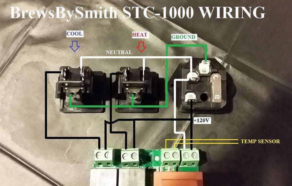
5 **If you are wiring in the optional Tri-Color LED, you will want to make sure and make your modifications and wiring to the STC-1000 before inserting it into the enclosure.** Now use the 14AWG black wire and solder a piece to the inlet connection leading forward into the enclosure to the side of the STC-1000 as seen in the photo below. I then

6 take 2 more pieces of black wire and connect all 3 next to the STC-1000 making sure to solder this connection very well and then using the adhesive lined shrink tube to cover it up. The 2 additional wires will now go to terminals 5 and 7 per the sticker on the unit. This is the relay inputs for the heat / cool circuits. To power the STC-1000 (terminals 1 and 2), you can use the smaller 20 AWG wire as it s easier to work with. Solder a piece of black wire to the inlet 120V and a piece of white wire to the inlet neutral. You can use the 14AWG if you like, its overkill but is more difficult to work with. Black wire should be secured to terminal 1 of the SCT-1000 and white wire goes to terminal 2 of the STC Now you can also attach the temperature sensor wires to terminals 3 and 4 on the STC- 1000, they are not polarity sensitive. Make sure all of your terminal connections are tight up to this point. Next take a couple of small pieces of the 14 AWG black wire and make connections from terminals 6 and 8 to the 120V connections on the outlets.
7
 14 AWG Black wire from terminal 7 to heat shrink at far right 14")
8 Picture below shows wiring connections and routing before the STC-1000 has been inserted and terminal connections made. From Left to right you see: 14 AWG Black wire from terminal 8 to cool outlet 120V (up-left side of outlet when looking at this view) 14 AWG Black wire from terminal 7 to heat shrink at far right 14 AWG Black wire from terminal 6 to heat outlet 120V (up-left side of outlet when looking at this view) 14 AWG Black wire from terminal 5 to heat shrink at far right Small black wire temperature sensor to terminal 4 Small black wire temperature sensor to terminal 3 20 AWG White wire from inlet neutral to terminal 2 20 AWG Black wire from inlet 120V to terminal 1 Heat shrink has 3 large black wires inside, 2 going to terminals 5 & 7, and the other going to inlet 120V After wiring is complete and STC-1000 inserted with terminal connections all tight, you can use the orange locking clips that slide along the rails of the plastic case, pushing them against the inside of the enclosure to secure everything in place. A Phillips screw driver is used to secure the 4 screws that hold the cover in place. Be careful as you plug things in and out of your SCT The STC-1000 is rated for 10 amps, it is strongly advised not to exceed this to avoid damage to the controller, your wiring, enclosure.

9 Optional Tri-Color LED wiring You will need to start by modifying your STC-1000 plastic case to allow room for the extra 3 wires that you will have to add to the PCB board connections at the relays. See photos below for a rough guideline. Attach the blue, red, and black wires to the corresponding points on the circuit board relay controls. Its best to try and scrape the clear coating off of the solder points before soldering your wires on. Pre-tin the wires also to make it easier. Once soldered on, make sure they are secure. You don t want wires bouncing around in there during assembly.

10 You will now want to double check your LED with a voltmeter if it has a diode check function, it looks like a triangle with a line through. See illustration of the LED below, take your positive probe to the common anode pin, pin 2, and then touch your black probe and touch the other pins, you should see the LED illuminate for each color faintly. Don t forget before making any of your solder connections to slide a piece of shrink tube far down the wire first, make sure to give yourself a lot more shrink tube on the red wire as you will have the resistor connection between the red wire and the LED common anode pin. The led pins can be shortened up, just do one at a time so you don t lose track of which pin is which. Solder the 2.2K resistor to the red wire, and then solder the resistor to the common anode pin. Solder the black wire (heat relay ground signal) to the red pin on the LED. Solder the blue wire (cool relay ground signal) to the blue pin on the LED. The green pin you won t use. You can carefully cut it off if you like or shrink tube over it. Before you heat the shrink tube up I personally like to verify the LED functions correctly first. If you are testing anything with the lid off make sure not to touch any of the exposed wires as this could injure or kill you.
11 ] To mount the LED, you will need to drill a ¼ hole into the case, make sure its spaced far enough away from the STC-1000 and it s mounting clips. Insert the LED holder all the way into the enclosure (pushing from the outside of the enclosure). The led once wired up and shrink tube shrunk will slide into the back of the LED holder. Make sure there is no tension on the wires as the LED holder doesn t hold it real strong, you don t want it sliding out the back. Route the LED wires away from the other soldered connections etc., you don t want a sharp solder point entering your 12v wire, this will cause severe damage if 120V gets applied to a 2 volt LED.

12 Photo below shows basic wire routing for LED and where I placed my LED holder. I used different color wire on my original build so don t let that confuse you. Once completed your cooling cycle will illuminate the LED BLUE, and the heating cycle will illuminate the LED RED. This is only once the relay has been energized. The blinking LED on the STC-1000 gives a warning that a heating or cooling cycle will be starting, your indication LED that you just wired in will not function in this manner.
Signal Mirror Installation Instructions Honda Odyssey
 Signal Mirror Installation Instructions 2005-2009 Honda Odyssey THE safety accessory of the 21st Century. P/N 210-0122-0 Rev. A4 (6/9/09), BTV 2006 Muth Company, LLC PROFESSIONAL INSTALLATION RECOMMENDED
Signal Mirror Installation Instructions
 Signal Mirror Installation Instructions 2005-2010 Chevy Corvette C6 THE safety accessory of the 21 st Century. P/N 210-0144-0 Rev. A3 (9/29/2011), BTV 2007 Muth Mirror Systems, LLC Page 3 of 10PplPage
Signal Mirror Installation Instructions
 Signal Mirror Installation Instructions 2006 2007 Honda Ridgeline THE safety accessory of the 21 st Century. P/N 210 0142 0 Rev. A (9/5/07), BTV 2007 Muth Company, LLC Professional Installation Recommended:
Installation Instructions Road King Classic Saddlebag Bezels
 Installation Instructions Road King Classic Saddlebag Bezels Thank you for your purchase of Bagger Audio Road King Classic Saddlebag Bezels for your Harley-Davidson motorcycle. We have carefully engineered
Applications: Section 1: Getting Started Tools Needed: BEFORE
 Installation of KBD Body Kits Porsche GT 3 Look/Style 2 Piece Polyurethane Front Bumper & Lip Applications: Porsche 996: 1999-2001 Porsche Boxster 986: 1997-2004 Page 1 Tools Needed: Philips Head Screwdriver
This instruction manual is an in-depth look and explanation of how to assemble and install the Murphy Bed properly and efficiently.
 This instruction manual is an in-depth look and explanation of how to assemble and install the Murphy Bed properly and efficiently. Don t be put off by the size of the instruction manual as the large diagrams
Starving Student II. Starving Student II. SS2 guide. Written By: 6L guides.diyaudio.com/ Page 1 of 24
 SS2 guide Written By: 6L6 2019 guides.diyaudio.com/ Page 1 of 24 INTRODUCTION This is a build guide for the hybrid headphone/pre-amplifier. You can buy a kit at the SSII product listing on the diyaudio
05-17 Mustang Fuel System Wire Upgrade Installation
 PARTS LIST: -10AWG INLINE FUSE HOLDER WITH 30AMP BLADE FUSE -16FT 10AWG HIGH CURRENT PRIMARY WIRE -40AMP AUTOMOTIVE RELAY -1FT 10AWG GROUND WIRE -1FT 10AWG HIGH CURRENT PRIMARY WIRE OUTPUT TO FPDM -1FT
AUDI A8 D3 REPLACING THE OUTSIDE DRIVER DOOR HANDLE
 AUDI A8 D3 REPLACING THE OUTSIDE DRIVER DOOR HANDLE The keyless entry system in the D3 is a great feature. If you have the car key fob in your pocket, putting your hand under the door handle will unlock
LP-200 Dummy Load / Wattmeter
 LP-200 Dummy Load / Wattmeter Enclosure Retrofit Assembly Instructions March 2009 TelePost Incorporated LP-200 is a trademark of TelePost Inc. Material in this document copyrighted 2009 TelePost Inc. 1
MICROGRANNY v2.1 - Assembly Guide
 last update: 9. 5. 2017 MICROGRANNY v2.1 - Assembly Guide bastl-instruments.com INTRODUCTION Welcome to the assembly guide for the MicroGranny kit. MicroGranny is a monophonic granular sampler by Bastl
EmagiKit. Privacy Pod Plus. Quiet. Easy. Affordable. INSTRUCTIONS ASSEMBLY
 EmagiKit Privacy Pod Plus Quiet. Easy. Affordable. INSTRUCTIONS ASSEMBLY DIMENSIONS AND COMPONENTS 47 47 Ceiling Unit 2-B 2-L 2-R Glass Door Corner Trim Door Handle 90 Adjustable Height Work Surface 1-B
Exterior Door Handle - LH - Unpainted (05-14 All)
") Tools Required: Exterior Door Handle - LH - Unpainted (05-14 All) 1) 10mm and 7mm sockets 2) Socket wrench (small size recommended) 3) T30 Torx bit 4) Plastic pry/molding tool (below, A) 5) Thin plastic
Tools Required: Exterior Door Handle - LH - Unpainted (05-14 All) 1) 10mm and 7mm sockets 2) Socket wrench (small size recommended) 3) T30 Torx bit 4) Plastic pry/molding tool (below, A) 5) Thin plastic
No crimping is required just solder the the wire to the crimp piece and use some heat shrink tubing to cover the end of the crimp.
 In this section we will be wiring up the IEC socket (AC plug) with the rocker switch and the Mains transformer primaries. Follow these instructions if you live in an area with 100, 110, 220 or 230 Volts!"
Bi-Color Signal Mirror Installation Instructions
 Bi-Color Signal Mirror Installation Instructions 2005-2009 Toyota Tacoma THE safety accessory of the 21 st Century. P/N 210-0141-0 Rev. A2 (3/30/09), BTV 2007 Muth Mirror Systems, LLC Page 3 of 13PplPage
BL-ER-P Ethernet Radio Unit for Pedestal Installation Guide
 Assemble the Antenna Riser 1. Remove the antenna riser assembly and the antenna from its packaging. 2. Remove the plastic cap, the nut, and the lock washer from the stem of the antenna. 3. Put the stem
C70 Window Roller Repair Taken from: Heres the problem:
 C70 Window Roller Repair Taken from: http://www.volvospeed.com/vs_forum/topic/115086-how-to-c70-window-rollers-permanent-fix/ Heres the problem: This happened to two separate window assemblys on my c70
EP-60 END OF CAR JUNCTION BOX KIT and ASSEMBLY AND INSTALLATION INSTRUCTIONS
 EP-60 END OF CAR JUNCTION BOX KIT 786282 and 786438 ASSEMBLY AND INSTALLATION INSTRUCTIONS Figure 1 EP-60 End of Car Junction Box Kit Item No. Qty. Description P/N Kit No. 786282 Kit No. 786438 1 2 Screw,
Bushwacker Jeep Flat Style Fender Flares Front Pair
 Bushwacker Jeep Flat Style Fender Flares Front Pair Note: These instructions involve cutting parts of your vehicle. Please read all instructions prior to starting. Installation Time: 3-4 Hours Tools Required:
* * APPLICABLE MODELS: 2014 > MAZDA 3
 PART NUMBER: 0000 8C L46 GENUINE ACCESSORIES INSTALLATION INSTRUCTIONS Rev. AAA *550-0604-000* APPLICABLE MODELS: 204 > MAZDA 3 REQUIRED COMPONENTS: ITEM QTY DESCRIPTION Usage Chart MIRROR ASSEMBLY: Mirror
ABC V1.0 ASSEMBLY IMPORTANT!
 ABC V1.0 ASSEMBLY Before starting this kit, prepare the following tools: Soldering iron (15-20W will do), flush cutters, no.2 hex screwdriver or allen key and phillips screwdriver. Also briefly go through
The ability to make basic voltage and resistance measurements using a digital multimeter
 Congratulations on your purchase of a new OneShot chassis! The PC01 OneShot combines a rugged enclosure, power supply, and discrete instrument DI in a compact 1/4U package. A few minutes of assembly are
Mini Cooper Lock Actuator
 2001-2006 Mini Cooper Lock Actuator Replacement This guide is on how to remove the lock actuator from the cars door. Written By: Jem ifixit CC BY-NC-SA www.ifixit.com Page 1 of 13 INTRODUCTION In order
The Wave (K-MOD103) GUITAR DWELL REVERB REVERB SWITCH ON OUT OFF
 GUITAR DWELL REVERB REVERB SWITCH ON OUT OFF") The Wave (K-MOD103) OUT IN GUITAR IN DWELL REVERB REVERB SWITCH ON GUITAR OUT POWER ON OFF OFF Please note, there are no labels for this kit. The controls, switches and connectors have only been labeled
The Wave (K-MOD103) OUT IN GUITAR IN DWELL REVERB REVERB SWITCH ON GUITAR OUT POWER ON OFF OFF Please note, there are no labels for this kit. The controls, switches and connectors have only been labeled
13MM FLAT WRENCH FOR LEVELING THE GLIDES OF STRUCTURE 6MM ALLEN KEY FOR ROOF CLIPS PHILLIPS HEAD BIT FOR SCREWS FOR DOOR FRAME
 1 TOOLS REQUIRED: MOVING CART/DOLLY FOR TRANSPORTING PANELS, ROOF, AND POSTS TWO 9 FT. STEP LADDERS FOR INSTALLING ROOF & PANELS REVERSIBLE RATCHET 1/4 DRIVE FOR CORNER SCREWS ON TOP TRAVERSE BEAMS ALTERNATIVE
Harmony Remote Repair
 Harmony Remote Repair harmonyremoterepair.com How to install your new Harmony One Front Cover/Touch Screen Important! Before you begin working on your Harmony One, you must discharge any static electricity
Transit Connect Full/Half Installation Instructions
 GATHER THESE TOOLS FOR ASSEMBLY & INSTALLATION 7/16 wrench, T45 Torx socket, 7/16 socket, 3/8 drive ratchet - 3/8 socket One 1/8 square end driver bit provided - Electric drill/driver/18v cordless One
Signal Mirror Installation Instructions Toyota Tacoma
 Signal Mirror Installation Instructions 2005-2015 Toyota Tacoma THE safety accessory of the 21 st Century. P/N 210-0115-0 Rev. A4 (3/11/15), BTV 2005 Muth Mirror Systems, LLC Page 3 of 12PplPage 3 of 12
GENUINE ACCESSORIES INSTALLATION INSTRUCTIONS. ITEM QTY DESCRIPTION Usage Chart
 PART NUMBER: 0000 8C R0 GENUINE ACCESSORIES INSTALLATION INSTRUCTIONS Rev. AAA *550-0554-000* APPLICABLE MODELS: 203 > CX-5 REQUIRED COMPONENTS: ITEM QTY DESCRIPTION Usage Chart MIRROR ASSEMBLY: Mirror
Water Level Meter: Op Instructions
 Equipment Check 1. Turn sensitivity switch fully clockwise. Notes: 1. Clockwise rotation of sensitivity swsitch turns meter on and increases sensitivity. 2. Always set switch to highest sensitivity position,
Assembly Instructions
 InTandem Table System November 20 InTandem Table System - Worksurface #4 x/" 4 wood screw power beam Tools Provided T-0 Extended Torx Driver T-25 Torx Driver Additional Tools Required Soft protective
Telecaster Wiring Kits Please Read All Instructions Before Beginning. Tools you will need: Soldering tips: Removing Current Wiring: Step 1. Step 2.
 Telecaster Wiring Kits Please Read All Instructions Before Beginning. Tools you will need: Soldering Iron (35 watt preferably) Solder Wet Sponge Wire Clippers Wire Strippers 3/8 Drill Bit 5/32 Drill Bit
MatterHackers. How to Install an E3D v6 HotEnd on a Lulzbot. Upgrade your TAZ with a shiny new E3D hotend. Written By: Ryan Lutz
 MatterHackers How to Install an E3D v6 HotEnd on a Lulzbot TAZ 5 Upgrade your TAZ with a shiny new E3D hotend. Written By: Ryan Lutz 2017 matterhackers.dozuki.com Page 1 of 21 INTRODUCTION NOTE: This guide
SUT-1000CLC ASSEMBLY REQUIREMENTS
 SUT-1000CLC Torque wrench, carpenters square, wire cutters, Phillips screwdriver, 7/16, 9/16, and 3/4 combination wrenches, ratchet, 9/16, 3/4, 13/16, and 7/8 sockets. ASSEMBLY REQUIREMENTS *Torque all
Team Xecuter Joycon Mod By: XxWiReDxX
 Team Xecuter Joycon Mod By: XxWiReDxX Works With Every Switch SX OS Works with every Nintendo Switch and every firmware version! Play Every Game With SX OS you can play all your favorite games straight
RPS. XR Front Drive Updates CORPORATION
 FACTORY CAT 1. To start a replacement of the XR Front Wheel Drive, make sure the machine is on level ground with the rear wheels chocked and always disconnect the batteries. 2. Locate the Positive and
Pacific Antenna RF Probe assembly
 Pacific Antenna RF Probe assembly Parts In the Kit: 1 1/2 x 3 Blue PEX tube 2 5/8 O.D. vinyl caps 2 3/32 dia x 2 brass tube sections 2 Pogo spring contacts 1 4-40 x 7/16 pan head screw 1 4-40 x 1/4 pan
QUALITY MANAGEMENT SYSTEM
 Not controlled in hard copy Rev. 1.0 Date: Page 1 of 18 Subject The following instructions provide a step-by-step procedure to replace the heating element for DEF/SCR/UREA/ADBLUE/DIESEL After Treatment
Instructions for Lighting an S Scale Caboose
 Instructions for Lighting an S Scale Caboose The S Scale Caboose lighting kit is adaptable for most caboose models of rolling stock including American Flyer (TM) and contains the same components as found
All Terrain Flares 2014 Chevy Silverado
 Page 1/8 Components: 1. Front Flares (2) 2. Rear Flares (2) Tools required: - Utility knife - #2 Phillips driver - Socket wrench - 13 mm Socket - 6 mm Allen Wrench - T-15 Torx bit - Trim Removal Tool -
Construction Guide European Version
 Construction Guide European Version PCB This section describes how to build up the DRO-350 printed circuit board (PCB). The bare PCB is available for purchase on the order page. Static Protection Bare
LITTLE NERD v1.1 Assembly Guide
 last update: 9. 3. 2016 LITTLE NERD v1.1 Assembly Guide bastl instruments.com INTRODUCTION This guide is for building Little Nerd module from Bastl Instruments. It is good to have basic soldering skills
Repairing your Porsche 928 Central Warning System (CWS) controller
 controller") Repairing your Porsche 928 Central Warning System (CWS) controller Disclaimer: This procedure is for a 1984 Porsche 928 S controller. Overview: Under the left foot pedal (dead pedal) of the Porsche 928
Repairing your Porsche 928 Central Warning System (CWS) controller Disclaimer: This procedure is for a 1984 Porsche 928 S controller. Overview: Under the left foot pedal (dead pedal) of the Porsche 928
Assembly Instructions Nevins Phone Booth
 Assembly Instructions Nevins Phone Booth Included Hardware Tools Required supplied by installer Drill & Bit Bolt A - (16) 1/4-20 x 1-1/2 hex head Bolt B - (20) 1/4-20 x 2-1/2 phillips head Screw 1 - (24)
BMW X5 OEM RUNNING BOARD PART#SBBW
 INSTALLATION INSTRUCTIONS 2014-2016 BMW X5 OEM RUNNING BOARD PART#SBBW-146-74 QTY HARDWARE 1 Driver Side OEM Running Board 1 Passenger Side OEM Running Board 8 Rivet Pin 1 Page Step 1: Verify all parts
Elecraft AF1 Audio Filter Enclosure
 Elecraft AF1 Audio Filter Enclosure by W8FGU Elecraft AF1 Audio Filter Mounted in the AF1 Enclosure (Courtesy of Ron D Eau Claire). The AF1 enclosure is made of Lexan, a polycarbonate, which is very strong.
The Bowflex Revolution XP Home Gym Assembly Instructions. P/N: Rev ( /0 )
") P/N: 001-7057 Rev ( /0 ) The Bowflex Revolution XP Home Gym Assembly Instructions 2 Table of Contents Before You Start... 2 Tools You Will Need / Hardware Contents... 3 Box Contents... 6 Assembling Your
P/N: 001-7057 Rev ( /0 ) The Bowflex Revolution XP Home Gym Assembly Instructions 2 Table of Contents Before You Start... 2 Tools You Will Need / Hardware Contents... 3 Box Contents... 6 Assembling Your
6MM ALLEN KEY FOR ROOF CLIPS PHILLIPS HEAD BIT FOR SCREWS FOR DOOR FRAME SPIRIT/LASER LEVEL TO LEVEL THE UNIT
 1 TOOLS REQUIRED: MOVING CART/DOLLY FOR TRANSPORTING PANELS, ROOF, AND POSTS TWO 9 FT. STEP LADDERS FOR INSTALLING ROOF & PANELS MINI REVERSIBLE RATCHET 1/4 DRIVE FOR CORNER SCREWS ON TOP TRAVERSE BEAMS
#4 Phillips Driver Bit 1/8, 4mm, 5.5mm & 8mm (5/16 ) Allen Wrench. Safety Glasses
 Allen Wrench. Safety Glasses") ATLANTIS RAIL Contact Information: Atlantis Rail Systems 70 Armstrong Road 3900 Civic Center Drive Plymouth, MA 02360 North Las Vegas, NV 89030 (800) 541-6829 or (508) 732-9191 (508) 732-9798 www.atlantisrail.com
ATLANTIS RAIL Contact Information: Atlantis Rail Systems 70 Armstrong Road 3900 Civic Center Drive Plymouth, MA 02360 North Las Vegas, NV 89030 (800) 541-6829 or (508) 732-9191 (508) 732-9798 www.atlantisrail.com
TRUE TECHNICAL SERVICE MANUAL - ALL MODELS. DOORS/DRAWERS/LIDS
 DOORS/DRAWERS/LIDS 55 56 NOTES DOORS/DRAWERS/LIDS Swing s 73 74 NOTES INSTALLATION OF A GDM-SWING DOOR Phillips Head Screwdriver (2) - 1/8" Drift Punches (forged) Top Bracket NOTE: It may be necessary
Powerpole General Assembly Instructions
 Powerpole General Assembly Instructions The contacts go in the housings in only one way. Insert the contacts with their sharp edge down against the flat spring that is in the housing. They should slide
Repairing Microsoft Wedge Touch Mouse Battery Cover Retaining Clip
 Repairing Microsoft Wedge Touch Mouse Battery Cover Retaining Clip Disassembly, repair and reassembly of Wedge Touch mouse when the battery cover will not stay closed. Also is a good guide to repair other
Fan, Eden/Northfield, GS Installation Instructions (SKU ) Packing List
 Packing List") Packing List Blower Assembly Wiring Harness Rheostat with Nut and Knob Snap Disc Mounting Hardware (4) rubber grommets with brass inserts, (4) nuts, (4) washers. Cover Assembly Installation Warning: Make
Packing List Blower Assembly Wiring Harness Rheostat with Nut and Knob Snap Disc Mounting Hardware (4) rubber grommets with brass inserts, (4) nuts, (4) washers. Cover Assembly Installation Warning: Make
Signal Mirror Installation Instructions
 Signal Mirror Installation Instructions Pontiac Grand Prix 1997-2003; Sedan and oupe THE safety accessory of the 21st entury. P/N 210-0018-0 Rev 2 (6-24-04), GG 2002 Muth Mirror Systems, LL. Note: Professional
INSTALLATION. Preparation:
 INSTALLATION Preparation: Average Time Required: 2 to 3 hours Place a blanket down in the area which you will be working in. This will prevent scratches on the rear fascia / valance. Remove your License
PERSONAL RECORD KEEPING
 Q47e/Q47ce 2 Q 4 7 e / Q 4 7 c e A s s e m b l y i n s t r u c t i o n s PERSONAL RECORD KEEPING IMPORTANT: Record the serial numbers of your Octane Fitness elliptical in the spaces below. This will make
Commercial Vehicle Productivity and Security. Antenna Configuration. External Antenna Installation (model 6650H only) Contigo 6650H/6651H Beacon
 Contigo 6650H/6651H Beacon") Commercial Vehicle Productivity and Security The 6650H/6651H is a versatile and economical GPS tracking beacon designed for fleet management needs in all commercial vehicles. The H designation in the model
Commercial Vehicle Productivity and Security The 6650H/6651H is a versatile and economical GPS tracking beacon designed for fleet management needs in all commercial vehicles. The H designation in the model
Installing the 3 Indexer: PRS Standard Tools
 888-680-4466 ShopBotTools.com Installing the 3 Indexer: PRS Standard Tools Copyright 2016 ShopBot Tools, Inc. page 1 Copyright 2016 ShopBot Tools, Inc. page 2 Table of Contents Route Cable into Box...5
Standard Kit #1 (3-way switch)
") Standard Kit #1 (3-way switch) Please Read All Instructions Before Beginning. Tools you will need: Soldering Iron (35 watt preferably) Solder Wet Sponge Wire Clippers 3/8 Drill Bit 1/4 Drill Bit Variable
Standard Kit #1 (3-way switch) Please Read All Instructions Before Beginning. Tools you will need: Soldering Iron (35 watt preferably) Solder Wet Sponge Wire Clippers 3/8 Drill Bit 1/4 Drill Bit Variable
Signal Mirror Installation Instructions Dodge Charger, Dodge Magnum, Chrysler 300
 Signal Mirror Installation Instructions 2006-2009 Dodge Charger, 2005-2008 Dodge Magnum, 2005-2009 Chrysler 300 THE safety accessory of the 21st Century. P/N 210-0123-0 Rev. A4 (10/7/09), BTV 2007 Muth
DIY Instructions For NGPC Front Light Installation using the Gameboy Advanced SP Front Light
 DIY Instructions For NGPC Front Light Installation using the Gameboy Advanced SP Front Light Tools you will need: Phillips Screwdriver Flat head Screwdriver Tri-wing Screwdriver Exacto Knife Soldering
EA6500 Antenna Installation Instructions:
 Thank you for purchasing the 6 Antenna Mod Kit for your Linksys router. First we will show you how to install the antennas for your router. Next we will teach you how to setup the DD-WRT firmware which
Droplit v2 Frame Assembly
 SeeMeCNC Guides Droplit v2 Frame Assembly Droplit v2 Frame Assembly Written By: JJ Johnson 2017 seemecnc.dozuki.com Page 1 of 22 Step 1 Droplit v2 Frame Assembly Locate the Projector Plate, Projector Joining
THE THUNDERDRIVE (K-950)
") THE THUNDERDRIVE (K-950) OUTPUT DISTORTION Unplug when not in use to save battery life. TO AMP IN The Thunderdrive Modkitsdiy.com FROM GUITAR OUT Use these instructions to learn: How to build an effects
THE THUNDERDRIVE (K-950) OUTPUT DISTORTION Unplug when not in use to save battery life. TO AMP IN The Thunderdrive Modkitsdiy.com FROM GUITAR OUT Use these instructions to learn: How to build an effects
INVENT3D Printer Kit Disassembly Instructions
 INVENT3D Printer Kit Disassembly Instructions Version 6 AST2 10/26/16 1 I. General Disassembly Instructions Use the case layer drawings to ensure that components are stored in the appropriate location
Read Below! Read Below! Read Below! Read Below! Read Below! Read Below! STOP READ TIPS BELOW TO MAKE ASSEMBLY MUCH EASIER
 Read Below! Read Below! Read Below! Read Below! Read Below! Read Below! STOP READ TIPS BELOW TO MAKE ASSEMBLY MUCH EASIER Here are some guidelines to help make assembling your unit much easier: -Read and
Ford F150 Front Bumper
 2009-2011 Ford F150 Front Bumper Warning! Read the instructions completely before beginning the installation. Before tightening bolts, drilling or cutting where required, check to make sure that there
Ribcage Installation. Part 2 - Assembly. Back-Bone V1.06
 Ribcage Installation Part 2 - Assembly Back-Bone V1.06 Contents Section 1 Before You Get Started... 2 Included With Your Kit:... 2 Figure: A... 3 CAUTION!... 4 Note:... 4 Tools Required... 5 Section 2:
RH-412 STEEL DOORS INSTALLATION INSTRUCTIONS
 RH-412 STEEL DOORS INSTALLATION INSTRUCTIONS By following the steps outlined below, the assembly, installation and adjustment of the steel doors, will be a simple process. Let s start with the Driver Side.
THE RING RESONATOR (K-975)
") THE RING RESONATOR (K-975) OUTPUT BOOST The Ring Resonator An Octave Up Fuzz Modkitsdiy.com 9 VDC CENTER (-) ADAPTER TO AMP IN FROM GUITAR OUT Unplug when not in use to save battery life. Use these instructions
THE RING RESONATOR (K-975) OUTPUT BOOST The Ring Resonator An Octave Up Fuzz Modkitsdiy.com 9 VDC CENTER (-) ADAPTER TO AMP IN FROM GUITAR OUT Unplug when not in use to save battery life. Use these instructions
INSTALLATION INSTRUCTIONS RH 412 STEEL DOORS
 By following the steps outlined below, the assembly, installation and adjustment of the steel doors, will be a simple process. Let s start with the Driver Side. Note: Having the hood open makes the job
Specimen Products Single Ended Stereo Amp Instruction Book
 Specimen Products Single Ended Stereo Amp Instruction Book Specimen tube amplifier designs are informed by decades of servicing and building musical instrument amps. As a result of being subjected to the
Manual Version July 2007
 Manual Version 1.2 - July 2007 Page 1 Table of Contents Section1: M3 Phono Board Build...3 Phono Board Parts List...3 Preparation...4 Fitting the Valve Bases...6 Installing the Resistors...7 Starting the
Assembly Instructions. GK2200T TREADMILL ASSEMBLY INSTRUCTIONS Frame Assembly 120V 220V
 GK2200T TREADMILL ASSEMBLY INSTRUCTIONS Frame Assembly 120V 220V IMPORTANT SAFETY INSTRUCTIONS Read and understand all instructions and warnings prior to use. Obtain a medical exam before beginning any
Value Location Qty Potentiometers C1M Distortion 1 A10k Volume 1. Footswitch 3PDT SW1 1. Jacks 1/4 Mono 2 DC Power 1
 Distortion BUILD INSTRUCTIONS Thank you for your purchase of our Distortion+ kit! We have completely redesigned our entire line of kits to be the most user friendly, while still maintaining their same
EDGE2 DUAL MONITOR ARM
 EDGE2 DUAL MONITOR ARM EDGE2 Rev A 2/17 Model EDGE2-SLV Model EDGE2-BLK Model EDGE2-WHT ASSEMBLY AND ADJUSTMENT EDGE2 DUAL MONITOR ARM PARTS AND TOOLS PLEASE REVIEW these instructions before beginning
SeeMeCNC Guides. Step 2. REV2 Rostock Max v3 Base Assembly. Second edition Rostock Max v3 assembly guide. Written By: JJ Johnson
 SeeMeCNC Guides Step 2. REV2 Rostock Max v3 Base Assembly Second edition Rostock Max v3 assembly guide. Written By: JJ Johnson INTRODUCTION This assembly guide will walk you though the steps of assembly
GORE Aerospace Ethernet Cables
 Termination Instructions The following procedures are based on Gore s best practices for terminating GORE Aerospace with the Carlisle Octax Connector System for both socket and plug versions. These procedures
MS2 Straight Key Kit Assembly Manual
 American Morse Equipment MS2 Straight Key Kit Assembly Manual Thank you for purchasing our MS2 Miniature Straight Key Kit! Please take a few minutes to look over these instructions before starting assembly.
ELECTRICAL CONNECTIONS
 ELECTRICAL CONNECTIONS Lesson 13 EET 150 Electrical Connections Learning Objectives In this lesson you will: see different methods of making electrical connections. learn a procedure for making soldered
626 - Mazda MX-6 - Mazda
 Factory Radio Other Documents Available For This Vehicle: No additional documents available at this time Adobe Acrobat Reader Printing Tips: 1) Select FLE then PRNT and select your printer. 2) n the print
Lexus ES350 Window Clip Replacement
 Page 1 of 10 1.0 Purpose The following instruction details the tools and supplies required, and the steps for removing and replacing the broken window clip in your 2007-2012 Lexus ES350. 2.0 Tools and
TRUE TECHNICAL SERVICE MANUAL - ALL MODELS. DOORS/DRAWERS/LIDS
 DOORS/DRAWERS/LIDS 55 56 NOTES DOORS/DRAWERS/LIDS Springs 97 TORSION SPRING REPLACEMENT GDM RADIUS FRONT - SWING DOOR INSTALLATION INSTRUCTIONS Tools Required (2) - 1 8" drift Punch (forged) Needle-Nose
Installation Instructions for Cirrus Suspension Downlight with Power - End Feed. Section One: 4" Flush Canopy Version
 Doc # 0-CSP-E_0 W. Fullerton Chicago, IL 606 Ph:.0. Fax:..6 www.pureedgelighting.com info@pureedgelighting.com 06 PureEdge Lighting. All Rights Reserved. Installation Instructions for Cirrus Suspension
THE TRILL TREMOLO (K-960)
") THE TRILL TREMOLO (K-60) DEPTH SPEED The Trill Tremolo Modkitsdiy.com Unplug when not in use to save battery life. TO AMP IN FROM GUITAR OUT Use these instructions to learn: How to build an effects pedal
THE TRILL TREMOLO (K-60) DEPTH SPEED The Trill Tremolo Modkitsdiy.com Unplug when not in use to save battery life. TO AMP IN FROM GUITAR OUT Use these instructions to learn: How to build an effects pedal
MEC Auto-Mate Assembly Manual. For MEC 9000G/GN and 8567 Grabber Series
 MEC Auto-Mate Assembly Manual For MEC 9000G/GN and 8567 Grabber Series Thank you We really appreciate your support of our product line. But our commitment to you hardly ends here. We won't be satisfied
ScaleRCHelis.com V Light Controller Kit
 Thank you for purchasing the ScaleRCHelis.com V1.1 450 Light Controller Kit. This is something you can build in under a hour with some simple soldering equipment. Your kit will include all the parts necessary
Digital Electronics & Chip Design
 Digital Electronics & Chip Design Lab Manual I: The Utility Board 1999 David Harris The objective of this lab is to assemble your utility board. This board, containing LED displays, switches, and a clock,
Removing and Replacing the Y-truck
 Service Documentation Removing and Replacing the Y-truck To remove and replace the Y-truck you will need the following tools: 4mm Allen wrench 12mm stamped flat wrench #2 Phillips screwdriver (magnetic
Hatchback Wing Riser Kit
 Hatchback Wing Riser Kit 2015-06-11 Thank you for purchasing this PERRIN product for your car! Installation of this product should only be performed by persons experienced with installation of aftermarket
7878 K940. Checkpoint Antenna. Kit Instructions. Issue B
 7878 K940 Checkpoint Antenna Kit Instructions Issue B Revision Record Issue Date Remarks A July 7, 2009 First issue B Nov2013 Revised the Checkpoint installation procedures for 7878 and 7874 scanners Added
Signal Mirror Installation Instructions
 Signal Mirror Installation Instructions Honda CRV 1997-2003 THE safety accessory of the 21 st Century. P/N 210-0032-0 Rev B2 (6-26-04), GG 2003 Muth Mirror Systems, LLC. Note: Professional Installation
Explorer Wiring Kit (assembled)
") Explorer Wiring Kit (assembled) For Vintage, Firestorm & Standard Series Please Read All Instructions Before Beginning. Tools you will need: Soldering Iron (35 watt preferably) Solder Wet Sponge Wire Clippers
Explorer Wiring Kit (assembled) For Vintage, Firestorm & Standard Series Please Read All Instructions Before Beginning. Tools you will need: Soldering Iron (35 watt preferably) Solder Wet Sponge Wire Clippers
Arducopter 3DR-B Hardware
 Arducopter 3DR-B Thank you for purchasing an Arducopter 3DR kit. The Arducopter 3DR is a stable and supported quadrotor frame in the ongoing development of the Arducopter code on DIYDrones. It features
Paco Motorsports Strong Arms X
 Paco Motorsports Strong Arms 13-101X Thanks for purchasing our Strong Arms. These braces reinforce the frame horns that support the engine and transfer all of the cornering and road impact loads into the
SIGNATURE FRONT BUMPER INSTALL
 SIGNATURE FRONT BUMPER INSTALL JL **PLEASE READ THROUGH THE INSTRUCTIONS BEFORE BEGINNING ANY PART OF THE INSTALLATION PROCESS** 1. You can now remove the trim strip (2 vertical clips, 4 horizontal, 2
American Morse Equipment
 American Morse Equipment Thank you for purchasing an American Morse Porta Paddle-II Kit. We redesigned the original Porta Paddle for ease of assembly & provide all parts finished and ready for assembly,
Chapter 6 Frame And Lens Repairs
 Chapter 6 Frame And Lens Repairs 6.1 General Information All maintenance on the frame of the EXO Full-Face mask can be accomplished with common hand tools. 6.2 Lens Replacement Tools required: Dow DC-111
THE AGGRESSOR (K-995)
") THE AGGRESSOR (K-99) TONE VOLUME DISTORTION MID-SHIFT SWITCH LED The Aggressor Distortion Pedal Modkitsdiy.com 9 VDC CENTER (-) ADAPTER TO AMP IN FROM GUITAR OUT Unplug when not in use to save battery
THE AGGRESSOR (K-99) TONE VOLUME DISTORTION MID-SHIFT SWITCH LED The Aggressor Distortion Pedal Modkitsdiy.com 9 VDC CENTER (-) ADAPTER TO AMP IN FROM GUITAR OUT Unplug when not in use to save battery
Line-Following Robot
 1 Line-Following Robot Printed Circuit Board Assembly Jeffrey La Favre October 5, 2014 After you have learned to solder, you are ready to start the assembly of your robot. The assembly will be divided