Does Your Receiver have an IQ?
|
|
|
- Rudolph Clarke
- 5 years ago
- Views:
Transcription
1 Does Your Receiver have an IQ? A Brief Presenta-on of how Radio Receivers have Evolved over the Decades of Radio, and Describing how some Modern SDR Receivers work using the Quadrature Sampling Detector, also known as the Tayloe Detector. 1
2 Recent Rigs I ve Built from Kits: BitX40 by Ashar Farhan. Based upon enthusias-c reports from Doug Miller, W4DML I have bought and built three of these SSB rigs. But I never looked deeply into how it worked, just had fun with it! Today I will show how it works when receiving signals. QCX by Hans Summers, QRP- Labs. I aoended the QRP seminar in Xenia( 4 Days in May) and was very impressed with Hans Summers presenta-on describing his new radio design. Hans lectured about implemen-ng a Quadrature Sampling Detector with a commonly used Digital Synthesis IC, he spoke about I and Q signals. I was completely unfamiliar with QSD, I & Q, and decided to find out about that. 2


3 BEFORE SOFTWARE DEFINED RADIOS, RADIO RECEIVERS RELIED ON THE MAGIC OF ELECTRIC AND ELECTROMAGNETIC FIELDS TO TUNE IN STATIONS CAPACITOR: STORES ENERGY IN THE ELECTRIC FIELD BETWEEN ITS PLATES INDUCTOR: STORES ENERGY IN AN ELECTROMAGNETIC FIELD 3
4 RESONANCE CONCEPTS Pu+ng inductors and capacitors together creates an electronic bell that rings or resonates. Inductor feeds capacitor; capacitor feeds inductor in a back and forth, reciprocal way. Resonance occurs when capacieve and induceve reactance values are equal: An LC circuit can store electrical energy oscilla-ng at its resonant frequency. A capacitor stores energy in the electric field between its plates, depending on the voltage across it, and an inductor stores energy in its magne-c field, depending on the current through it. 4


5 IN A PARALLEL CIRCUIT OF BOTH CAPACITIVE AND INDUCTIVE REACTANCES, AT RESONANCE THE CIRCUIT HAS INFINITE IMPEDANCE WHICH PREVENTS CURRENT FLOW TO THE LOAD Experiment #5 Schema-c 5

6 DIODE DETECTOR (ENVELOPE DETECTOR) (The earphone in this example has capacitance) With one side of the LC circuit -ed to an antenna, and the other side to ground, signals captured by the antenna that are not at the resonate frequency of the circuit are passed through the circuit to ground. Signals that are at the resonate frequency do not get shunted to ground and are available for detec-on by a Germanium diode rec-fier. 6

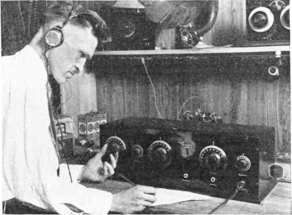
7 THE TUNED RADIO FREQUENCY RECEIVER (TRF) CONTAINS TWO OR THREE TUNED RF AMPLIFICATION STAGES BEFORE THE DETECTOR 7

8 Each RF stage of a TRF receiver had to be tuned to the same frequency, so the capacitors had to be tuned in tandem when bringing in a new sta-on. In some later sets the capacitors were "ganged", mounted on the same shah or otherwise linked mechanically so that the radio could be tuned with a single knob, but in most sets the resonant frequencies of the tuned circuits could not be made to "track" well enough to allow this, and each stage had its own tuning knob 8
9 9

10 TRF RECEIVER GANGED VARIABLE CAPACITOR 10
11 The major problem with the TRF receiver, par-cularly as a consumer product, was its complicated tuning Note that this is a simple and straight forward design, and most of the circuits disadvantages would not apply if the receiver was used for one frequency only. Cascading RF gain stages works well for a single frequency. This is the basic principle of the superheterodyne receiver. 11
12 THE SUPERHETERODYNE RECEIVER (Superhet) INVENTED BY EDWIN ARMSTRONG IN 1918, REPLACED THE TRF RECEIVERS BY THE MID 30 S. Armstrong built a cascade of fix- tuned amplifiers at a low frequency where a large amount of stable gain was easy to obtain and. Then he preceded this amplifier cascade with a frequency translator or mixer stage in order to convert or heterodyne the desired signal to the new intermediate frequency or IF. Armstrong called this new receiver (which used heterodyning to translate signals to a fixed, lower intermediate frequency for recep-on) the superheterodyne receiver. 12
13 SUPERHET BLOCK DIAGRAM TYPICAL AM RADIO INTERMEDIATE FREQUENCY (IF) = 455KHZ FOR BROADCAST BAND FREQUENCIES OF 530KHZ AND 1700KHZ TYPICAL AM RADIO LOCAL OSCILLATOR (LO) TRACKS BETWEEN 985KHZ AND 2155KHZ 13
14 SUM AND DIFFERENCE PRODUCTS OF THE INPUT SIGNAL AND THE LOCAL OSCILLATOR ARE PRODUCED. The essen-al characteris-c of a mixer is that it produces a component in its output which is the product of the two input signals. A device that has a non- linear (e.g. exponen-al) characteris-c can act as a mixer. Passive mixers use one or more diodes and rely on their non- linear rela-on between voltage and current to provide the mul-plying element. In a passive mixer, the desired output signal is always of lower power than the input signals. 14

15 The local oscillator frequency is determined by a variable capacitor that is ganged to the main receiver tuning variable capacitor 15


16 GANGED CAPACITORS THE CAPACITOR FOR THIS RADIO 16
 FROM Si5351 SYNTH PRODUCT DETECTOR")
17 DIODE MIXER THE BITX40 HAS A SUPERHETERODYNE RECEIVER 3 POLE BANDPASS FILTER REQUIRES NO TUNING LOCAL OSCILLATOR (LO) FROM Si5351 SYNTH PRODUCT DETECTOR DEMODULATOR 17

18 THE BITX40 USES A 12MHZ INTERMEDIATE FREQUENCY. THE LOCAL OSCILLATOR IS AN ARDUINO CONTROLLED FREQUENCY SYNTHESIZER THAT OUTPUTS A SIGNAL THAT WILL ADD TO THE DIAL OR DISPLAYED FREQUENCY TO EQUAL 12 MHZ. FOR EXAMPLE, IT THE BITX40 IS TUNED FOR 7MHZ SHOWN ON THE LCD DISPLAY, THE LOCAL OSCILLATOR WILL BE RUNNING AT 5MHZ. 5+7 = 12 18
19 AN INTRODUCTION TO A QUADRATURE SAMPLING DETECTOR THE TAYLOE DETECTOR I and Q stand for In Phase and Quadrature Phase. The quadrature Phase is merely the signal shihed by 90 degrees from the In Phase Signal. QSD means Quadrature Sampling Detector. Give Me I and Q and I Can Demodulate Anything Gerald Youngblood, AC5OG, Flex Radio CEO If you have both the I and the Q data, you can demodulate any kind of modula-on Invented by Dan Tayloe N7VE in 2001, it is a famous high performance Quadrature Sampling Detector Hans Summers, G0UPL, QRP- Labs 19

20 Quadrature Signal Concepts If the phase Ф difference between two sinusoids is 90 degrees (or π /2 radians), then these two signals are said to be in quadrature. An example of this is the sine wave and the cosine wave. By conven-on, the cosine wave is in- phase component and the sine wave is the quadrature component. The capital leoer I represents the amplitude of the in- phase signal, and the capital leoer Q represents the amplitude of the quadrature signal. 20

21 If both I and Q were equal to 1, then the sum will be a new signal that is shown graphically below By now you can see that the amplitude and the phase of the sum of the quadrature signals is a func-on of the value of I and Q. 21

22 By mixing an RF signal with LO (local oscillator) signals in quadrature, I(t) and Q(t) baseband signals can be created. This is the fundamental basis for most modern RF signal demodula-on. 22
 signal and the 90 and 270 capacitors sum to provide the quadrature (Q) signal.")
23 Tayloe detector: The switch rotates at the carrier frequency so that each capacitor samples the signal once each revolueon. The 0 and 180 capacitors differeneally sum to provide the in- phase (I) signal and the 90 and 270 capacitors sum to provide the quadrature (Q) signal. The capacitors act as sample and hold and contain the voltage corresponding to each switched value for summing in the amplifiers. This works like an envelope detector formed by the capacitor following the diode in an am radio. 23

24 TWO BIT COUNTER OUTPUT Ohen a divide- by- 4 circuit is used, to produce quadrature oscillator outputs from an oscillator input at 4x the recep-on frequency. This also creates challenges par-cularly as you try to increase the recep-on frequency to cover higher bands. For example, on 10m e.g. 30MHz, a local oscillator at 120MHz is required and the divide- by- 4 circuit must be able to operate at such a high frequency. Devices such as the 74AC74 can do so, but pushing it higher into the 6m band cannot be done with the 74AC74. 24

25 The Si5351A has a phase offset feature, which is not really very clearly described in the SiLabs documenta-on. However, QRP Labs has perfected the technique to put two of the Si5351A outputs into precise 90- degree quadrature, which is maintained without tuning glitches as the frequency is altered. It s a nice development because it eliminates one more circuit block. To the best of my knowledge this the first Eme the Si5351A has been implemented in a product directly driving a QSD with two outputs in quadrature (no divide- by- 4 circuit). Hans Summers 25
26 THE QRP- LABS QCX RECEIVER FRONT END A DIRECT CONVERSION RECEIVER 26

27 MIXER, CREATES QUADRATURE AF SIGNAL IQ AUDIO HERE USES THE Si5351 IC JUST LIKE THE BITX40 AND THE QCX! IQ ANALOG TO DIGITAL CONVERTER 27
28 A SoCware- Defined Radio for the Masses, Part 1 By: Gerald Youngblood AC5OG QEX Jul/Aug 2002 Tektronix Blog What s Your IQ About Quadrature Signals by: Alan Wolke Sohware Defined Radio for amateur radio operators and shortwave listeners 2016 and 2018 (Kindle Revision) by: Andrew Barron ZL3DW QCX: 5W CW Transceiver kit assembly instruc-ons Designed and produced by QRP Labs, 2017 by: Hans Summers Communica-ons Electronics 2 nd Edi-on 1972 By: J.J. DeFrance Quadrature Mixers, IQ DemodulaEon, and the Tayloe Detector Aug 10, Uploaded by devoys0 hops:// 28
Modernization of QRP RADIOS and Development of the QCX transceiver Hans Summers G0UPL
 Modernization of QRP RADIOS and Development of the QCX transceiver Hans Summers G0UPL http://qrp-labs.com Introduction and 3 topics Introduction to the QCX transceiver Three topics: 1. Improving QRP radio
Topic Advanced Radio Receivers. Explain that an RF amplifier can be used to improve sensitivity;
 Learning Objectives: At the end of this topic you will be able to; Explain that an RF amplifier can be used to improve sensitivity; Explain that a superheterodyne receiver offers improved selectivity and
Technician License Course Chapter 3 Types of Radios and Radio Circuits. Module 7
 Technician License Course Chapter 3 Types of Radios and Radio Circuits Module 7 Radio Block Diagrams Radio Circuits can be shown as functional blocks connected together. Knowing the description of common
Description of the AM Superheterodyne Radio Receiver
 Superheterodyne AM Radio Receiver Since the inception of the AM radio, it spread widely due to its ease of use and more importantly, it low cost. The low cost of most AM radios sold in the market is due
The New England Radio Discussion Society electronics course (Phase 4, cont d) Introduction to receivers
 Introduction to receivers") The New England Radio Discussion Society electronics course (Phase 4, cont d) Introduction to receivers AI2Q April 2017 REVIEW: a VFO, phase-locked loop (PLL), or direct digital synthesizer (DDS), can
The New England Radio Discussion Society electronics course (Phase 4, cont d) Introduction to receivers AI2Q April 2017 REVIEW: a VFO, phase-locked loop (PLL), or direct digital synthesizer (DDS), can
Radio Receivers. Al Penney VO1NO
 Radio Receivers Al Penney VO1NO Role of the Receiver The Antenna must capture the radio wave. The desired frequency must be selected from all the EM waves captured by the antenna. The selected signal is
RF/IF Terminology and Specs
 RF/IF Terminology and Specs Contributors: Brad Brannon John Greichen Leo McHugh Eamon Nash Eberhard Brunner 1 Terminology LNA - Low-Noise Amplifier. A specialized amplifier to boost the very small received
NEW YORK CITY COLLEGE of TECHNOLOGY THE CITY UNIVERSITY OF NEW YORK DEPARTMENT OF ELECTRICAL ENGINEERING AND TELECOMMUNICATIONS TECHNOLOGIES
 NEW YORK CITY COLLEGE of TECHNOLOGY THE CITY UNIVERSITY OF NEW YORK DEPARTMENT OF ELECTRICAL ENGINEERING AND TELECOMMUNICATIONS TECHNOLOGIES Course : EET 24 Communications Electronics Module : AM Tx and
Analog & Digital Communication
 Analog & Digital Communication UNIT I Tuned Radio Frequency Receiver Outline Basic Receiver TRF block diagram Advantages Disadvantages Basic receiver -1 Basic receiver -2 If there are many stations then
Radio Receivers. Al Penney VO1NO
 Radio Receivers Role of the Receiver The Antenna must capture the radio wave. The desired frequency must be selected from all the EM waves captured by the antenna. The selected signal is usually very weak
Twelve voice signals, each band-limited to 3 khz, are frequency -multiplexed using 1 khz guard bands between channels and between the main carrier
 Twelve voice signals, each band-limited to 3 khz, are frequency -multiplexed using 1 khz guard bands between channels and between the main carrier and the first channel. The modulation of the main carrier
OBJECTIVES EQUIPMENT LIST
 1 Reception of Amplitude Modulated Signals AM Demodulation OBJECTIVES The purpose of this experiment is to show how the amplitude-modulated signals are demodulated to obtain the original signal. Also,
Module 8 Theory. dbs AM Detector Ring Modulator Receiver Chain. Functional Blocks Parameters. IRTS Region 4
 Module 8 Theory dbs AM Detector Ring Modulator Receiver Chain Functional Blocks Parameters Decibel (db) The term db or decibel is a relative unit of measurement used frequently in electronic communications
CHAPTER 13 TRANSMITTERS AND RECEIVERS
 CHAPTER 13 TRANSMITTERS AND RECEIVERS Frequency Modulation (FM) Receiver Frequency Modulation (FM) Receiver FREQUENCY MODULATION (FM) RECEIVER Superheterodyne Receiver Heterodyning The word heterodyne
Introduction to Amplitude Modulation
 1 Introduction to Amplitude Modulation Introduction to project management. Problem definition. Design principles and practices. Implementation techniques including circuit design, software design, solid
ENSC327 Communications Systems 5: Frequency Translation (3.6) and Superhet Receiver (3.9)
 and Superhet Receiver (3.9)") ENSC327 Communications Systems 5: Frequency Translation (3.6) and Superhet Receiver (3.9) Jie Liang School o Engineering Science Simon Fraser University 1 Outline Frequency translation (page 128) Superhet
ENSC327 Communications Systems 5: Frequency Translation (3.6) and Superhet Receiver (3.9) Jie Liang School o Engineering Science Simon Fraser University 1 Outline Frequency translation (page 128) Superhet
This place covers: Demodulation or transference of signals modulated on a sinusoidal carrier or on electromagnetic waves.
 CPC - H03D - 2017.08 H03D DEMODULATION OR TRANSFERENCE OF MODULATION FROM ONE CARRIER TO ANOTHER (masers, lasers H01S; circuits capable of acting both as modulator and demodulator H03C; details applicable
Vintage Radio Alignment: What It Is and How to Do It
 Vintage Radio Alignment: What It Is and How to Do It Copyright 2009 Bret s Old Radios Bret Menassa Member: ARCI, VRPS, OKVRC Presented at Radiofest 2009, Willowbrook,, IL Vibrations A musical instrument
EE470 Electronic Communication Theory Exam II
 EE470 Electronic Communication Theory Exam II Open text, closed notes. For partial credit, you must show all formulas in symbolic form and you must work neatly!!! Date: November 6, 2013 Name: 1. [16%]
ANALOG COMMUNICATION
 ANALOG COMMUNICATION TRAINING LAB Analog Communication Training Lab consists of six kits, one each for Modulation (ACL-01), Demodulation (ACL-02), Modulation (ACL-03), Demodulation (ACL-04), Noise power
Superheterodyne Receiver Tutorial
 1 of 6 Superheterodyne Receiver Tutorial J P Silver E-mail: john@rfic.co.uk 1 ABSTRACT This paper discusses the basic design concepts of the Superheterodyne receiver in both single and double conversion
BITX20 Transceiver. What is a BITX BITX History The Discussion Group BITX Today Future Directions
 BITX20 Transceiver What is a BITX BITX History The Discussion Group BITX Today Future Directions What is a BITX A 6 watt SSB Transceiver for 20M designed by Farhan VU2ESE An International Discussion Group
Chapter 5 AM Receivers
 Chapter 5 AM Receivers Prepared by Prof.V.K.Jain 1 Lecture outcome After studying this lecture, you should be able to: Describe the basic superheterodyne system Choose suitable intermediate frequencies
HF Receivers, Part 2
 HF Receivers, Part 2 Superhet building blocks: AM, SSB/CW, FM receivers Adam Farson VA7OJ View an excellent tutorial on receivers NSARC HF Operators HF Receivers 2 1 The RF Amplifier (Preamp)! Typical
Exercise 2: Demodulation (Quadrature Detector)
") Analog Communications Angle Modulation and Demodulation Exercise 2: Demodulation (Quadrature Detector) EXERCISE OBJECTIVE When you have completed this exercise, you will be able to explain demodulation
Analog Communications Angle Modulation and Demodulation Exercise 2: Demodulation (Quadrature Detector) EXERCISE OBJECTIVE When you have completed this exercise, you will be able to explain demodulation
4/30/2012. General Class Element 3 Course Presentation. Practical Circuits. Practical Circuits. Subelement G7. 2 Exam Questions, 2 Groups
 General Class Element 3 Course Presentation ti ELEMENT 3 SUB ELEMENTS General Licensing Class Subelement G7 2 Exam Questions, 2 Groups G1 Commission s Rules G2 Operating Procedures G3 Radio Wave Propagation
Chapter 6: Power Amplifiers
 Chapter 6: Power Amplifiers Contents Class A Class B Class C Power Amplifiers Class A, B and C amplifiers are used in transmitters Tuned with a band width wide enough to pass all information sidebands
Chapter 6. FM Circuits
 Chapter 6 FM Circuits Topics Covered 6-1: Frequency Modulators 6-2: Frequency Demodulators Objectives You should be able to: Explain the operation of an FM modulators and demodulators. Compare and contrast;
Albert F. Peter AC8GY Aug. 12, 2010
 Albert F. Peter AC8GY Aug. 12, 2010 Software-defined not software-controlled radio Most of the complex signal handling uses DSP User interface through the computer Usually some form of direct conversion
Transmitters and receivers
 Chapter 3 Transmitters and receivers Transmitters and receivers are used extensively in aircraft communication and navigation systems. In conjunction with one ore more antennas, they are responsible for
Lecture 12. Carrier Phase Synchronization. EE4900/EE6720 Digital Communications
 EE49/EE6720: Digital Communications 1 Lecture 12 Carrier Phase Synchronization Block Diagrams of Communication System Digital Communication System 2 Informatio n (sound, video, text, data, ) Transducer
Receiver Architectures
 Receiver Architectures Modules: VCO (2), Quadrature Utilities (2), Utilities, Adder, Multiplier, Phase Shifter (2), Tuneable LPF (2), 100-kHz Channel Filters, Audio Oscillator, Noise Generator, Speech,
Exercise 1: RF Stage, Mixer, and IF Filter
 SSB Reception Analog Communications Exercise 1: RF Stage, Mixer, and IF Filter EXERCISE OBJECTIVE DISCUSSION On the circuit board, you will set up the SSB transmitter to transmit a 1000 khz SSB signal
General Class License Theory II. Dick Grote K6PBF
 General Class License Theory II Dick Grote K6PBF k6pbfdick@gmail.com 1 Introduction In the first theory class we talked about basic electrical principles and components. Now we will build on this to learn
THE AMAZING BARLOW WADLEY XCR-30 CRYSTAL CONTROLLED 30 BAND TRANSISTOR RADIO. (A method to set the AGC) H. Holden, 2018.
 H. Holden, 2018.") THE AMAZING BARLOW WADLEY XCR-30 CRYSTAL CONTROLLED 30 BAND TRANSISTOR RADIO. (A method to set the AGC) H. Holden, 2018. Introduction: The Barlow Wadley XCR-30 radio is well known to amateur radio enthusiasts
THE AMAZING BARLOW WADLEY XCR-30 CRYSTAL CONTROLLED 30 BAND TRANSISTOR RADIO. (A method to set the AGC) H. Holden, 2018. Introduction: The Barlow Wadley XCR-30 radio is well known to amateur radio enthusiasts
DSP COMMUNICATIONS EXPERIMENT
 Introduction DSP COMMUNICATIONS EXPERIMENT Gale Allen, Ph.D. Electrical and Computer Engineering and Technology Department (ECET) Minnesota State University, Mankato The laboratory experiments used in
AM Generation High Level Low Level
 AM Generation High Level Low Level Low-level generation In modern radio systems, modulated signals are generated via digital signal processing (DSP). With DSP many types of AM modulation are possible with
DSP Communications Experiment Gale Allen, Minnesota State University, Mankato
 DSP Communications Experiment Gale Allen, Minnesota State University, Mankato Abstract A sampling circuit combined with digital implementation of analog communications functions and the evolution of experiments
Lecture 6. Angle Modulation and Demodulation
 Lecture 6 and Demodulation Agenda Introduction to and Demodulation Frequency and Phase Modulation Angle Demodulation FM Applications Introduction The other two parameters (frequency and phase) of the carrier
Introduction to Receivers
 Introduction to Receivers Purpose: translate RF signals to baseband Shift frequency Amplify Filter Demodulate Why is this a challenge? Interference Large dynamic range required Many receivers must be capable
Experiment No. 2 Pre-Lab Signal Mixing and Amplitude Modulation
 Experiment No. 2 Pre-Lab Signal Mixing and Amplitude Modulation Read the information presented in this pre-lab and answer the questions given. Submit the answers to your lab instructor before the experimental
FM Superheterodyne Receiver
 EE321 Final Project Chun-Hao Lo XiaoKai Sun Background: FM Superheterodyne Receiver Superheterodyne Receiver is the receiver that convert a received signal from the transmitter to an intermediate frequency.
COMM 704: Communication Systems
 COMM 704: Communication Lecture 1: Introduction Dr. Mohamed Abd El Ghany, Mohamed.abdel-ghany@guc.edu.eg Course Objective Give an introduction to the basic concepts of electronic communication systems
Code No: R Set No. 1
 Code No: R05220405 Set No. 1 II B.Tech II Semester Regular Examinations, Apr/May 2007 ANALOG COMMUNICATIONS ( Common to Electronics & Communication Engineering and Electronics & Telematics) Time: 3 hours
MAHALAKSHMI ENGINEERING COLLEGE TIRUCHIRAPALLI UNIT III TUNED AMPLIFIERS PART A (2 Marks)
") MAHALAKSHMI ENGINEERING COLLEGE TIRUCHIRAPALLI-621213. UNIT III TUNED AMPLIFIERS PART A (2 Marks) 1. What is meant by tuned amplifiers? Tuned amplifiers are amplifiers that are designed to reject a certain
MAHALAKSHMI ENGINEERING COLLEGE TIRUCHIRAPALLI-621213. UNIT III TUNED AMPLIFIERS PART A (2 Marks) 1. What is meant by tuned amplifiers? Tuned amplifiers are amplifiers that are designed to reject a certain
1. General Outline Project Proposal April 9, 2014 Kayla Esquivel and Jason Yang
 1. General Outline 6.101 Project Proposal April 9, 2014 Kayla Esquivel and Jason Yang The invention and mass application of radio broadcast was triggered in the first decade of the nineteenth century by
EE301 ELECTRONIC CIRCUITS CHAPTER 2 : OSCILLATORS. Lecturer : Engr. Muhammad Muizz Bin Mohd Nawawi
 EE301 ELECTRONIC CIRCUITS CHAPTER 2 : OSCILLATORS Lecturer : Engr. Muhammad Muizz Bin Mohd Nawawi 2.1 INTRODUCTION An electronic circuit which is designed to generate a periodic waveform continuously at
RADIO RECEIVERS ECE 3103 WIRELESS COMMUNICATION SYSTEMS
 RADIO RECEIVERS ECE 3103 WIRELESS COMMUNICATION SYSTEMS FUNCTIONS OF A RADIO RECEIVER The main functions of a radio receiver are: 1. To intercept the RF signal by using the receiver antenna 2. Select the
Tuned Radio Frequency Receiver (TRF) The most elementary receiver design, consisting of RF amplifier stages, detector and audio amplifier stages.
 The most elementary receiver design, consisting of RF amplifier stages, detector and audio amplifier stages.") Figure 3-1 Simple radio receiver block diagram. Tuned Radio Frequency Receiver (TRF) The most elementary receiver design, consisting of RF amplifier stages, detector and audio amplifier stages. Jeffrey
Figure 3-1 Simple radio receiver block diagram. Tuned Radio Frequency Receiver (TRF) The most elementary receiver design, consisting of RF amplifier stages, detector and audio amplifier stages. Jeffrey
Analog RF Electronics Education at SDSMT: A Hands-On Method for Teaching Electrical Engineers
 Analog RF Electronics Education at : A Hands-On Method for Teaching Electrical Engineers Dr., Professor Department of Electrical and Computer Engineering South Dakota School of Mines and Technology (whites@sdsmt.edu)
Amateur Wireless Station Operators License Exam
 Amateur Wireless Station Operators License Exam Study material 2017 South India Amateur Radio Society, Chennai CHAPTER 4 1 Chapter 4 Amateur Wireless Station Operators License Exam Study Material Chapter
Norfolk Amateur Radio Club
 Norfolk Amateur Radio Club The Transmitter & Transmitter Interference Nick M0HGU & Steve G3PND Plan for the Day The Transmitter Introduction, Block diagrams Oscillators, Buffers & Multipliers Modulation
NOISE PERFORMANCE CHARACTERSITICS OF DIRECT CONVERSION RECEIVERS
 White Paper NOISE PERFORMANCE CHARACTERSITICS OF DIRECT CONVERSION RECEIVERS January 2012 Austin, Texas Stephen Hicks, N5AC, AAR6AM, VP Engineering, FlexRadio Systems HISTORY AND THE PROBLEM Superheterodyne,
Receiver Operation at the Component Level
 Receiver Operation at the Component Level Unit 9. Activity 9.4. How a Receiver Works Purpose: The objective of this lesson is to allow the student to explore how a receiver works at the component level.
6.101 Introductory Analog Electronics Laboratory
 6.101 Introductory Analog Electronics Laboratory Spring 2015, Instructor Gim Hom Project Proposal Transmitting, Receiving, and Interpreting ECG Waveforms Daniel Moon (dhmoon@mit.edu) Thipok (Ben) Rak-amnouykit
Modern QRP Rigs and the Development of the QCX CW Transceiver Kit
 Modern QRP Rigs and the Development of the QCX CW Transceiver Kit Introduction I present an attempt to describe some of the more modern techniques into QRP radio design. The majority of QRP radio receivers
Definitions. Spectrum Analyzer
 SIGNAL ANALYZERS Spectrum Analyzer Definitions A spectrum analyzer measures the magnitude of an input signal versus frequency within the full frequency range of the instrument. The primary use is to measure
RADIO AMATEUR EXAM GENERAL CLASS
 RAE-Lessons by 4S7VJ 1 CHAPTER-5 RADIO AMATEUR EXAM GENERAL CLASS By 4S7VJ 5.1 RECEIVER The main purpose of a radio receiver is receive RF signal and convert to AF signal or get the audio signal out from
Communication Circuit Lab Manual
 German Jordanian University School of Electrical Engineering and IT Department of Electrical and Communication Engineering Communication Circuit Lab Manual Experiment 3 Crystal Oscillator Eng. Anas Alashqar
CHAPTER 6 Radio Circuits and Systems
 6.1 AMPLIFIERS (page 6-1) CHAPTER 6 Radio Circuits and Systems AMPLIFIER GAIN (page 6-2) INPUT AND OUTPUT IMPEDANCE (page 6-2) DISCRETE DEVICE AMPLIFIERS (page 6-2) BASIC CIRCUITS (page 6-2) COMMON-EMITTER
Design of a Regenerative Receiver for the Short-Wave Bands A Tutorial and Design Guide for Experimental Work. Part I
 Design of a Regenerative Receiver for the Short-Wave Bands A Tutorial and Design Guide for Experimental Work Part I Ramón Vargas Patrón rvargas@inictel-uni.edu.pe INICTEL-UNI Regenerative Receivers remain
Session 3. CMOS RF IC Design Principles
 Session 3 CMOS RF IC Design Principles Session Delivered by: D. Varun 1 Session Topics Standards RF wireless communications Multi standard RF transceivers RF front end architectures Frequency down conversion
List of Figures. Sr. no.
 List of Figures Sr. no. Topic No. Topic 1 1.3.1 Angle Modulation Graphs 11 2 2.1 Resistor 13 3 3.1 Block Diagram of The FM Transmitter 15 4 4.2 Basic Diagram of FM Transmitter 17 5 4.3 Circuit Diagram
Part I - Amplitude Modulation
 EE/CME 392 Laboratory 1-1 Part I - Amplitude Modulation Safety: In this lab, voltages are less than 15 volts and this is not normally dangerous to humans. However, you should assemble or modify a circuit
Technician License Course Chapter 3. Lesson Plan Module 7 Types of Radio Circuits
 Technician License Course Chapter 3 Lesson Plan Module 7 Types of Radio Circuits The Basic Transceiver Combination of transmitter and receiver Abbreviated XCVR (X = trans) Antenna switched between transmitter
Week 8 AM Modulation and the AM Receiver
 Week 8 AM Modulation and the AM Receiver The concept of modulation and radio transmission is introduced. An AM receiver is studied and the constructed on the prototyping board. The operation of the AM
Introduction. In the frequency domain, complex signals are separated into their frequency components, and the level at each frequency is displayed
 SPECTRUM ANALYZER Introduction A spectrum analyzer measures the amplitude of an input signal versus frequency within the full frequency range of the instrument The spectrum analyzer is to the frequency
RF Integrated Circuits
 Introduction and Motivation RF Integrated Circuits The recent explosion in the radio frequency (RF) and wireless market has caught the semiconductor industry by surprise. The increasing demand for affordable
B.Tech II Year II Semester (R13) Supplementary Examinations May/June 2017 ANALOG COMMUNICATION SYSTEMS (Electronics and Communication Engineering)
 Supplementary Examinations May/June 2017 ANALOG COMMUNICATION SYSTEMS (Electronics and Communication Engineering)") Code: 13A04404 R13 B.Tech II Year II Semester (R13) Supplementary Examinations May/June 2017 ANALOG COMMUNICATION SYSTEMS (Electronics and Communication Engineering) Time: 3 hours Max. Marks: 70 PART A
Code: 13A04404 R13 B.Tech II Year II Semester (R13) Supplementary Examinations May/June 2017 ANALOG COMMUNICATION SYSTEMS (Electronics and Communication Engineering) Time: 3 hours Max. Marks: 70 PART A
Operating Manual Ver 1.1
 Frequency Modulation and Demodulation Trainer ST2203 Operating Manual Ver 1.1 An ISO 9001 : 2000 company 94-101, Electronic Complex Pardesipura, Indore- 452010, India Tel : 91-731- 2570301/02, 4211100
RFID Systems: Radio Architecture
 RFID Systems: Radio Architecture 1 A discussion of radio architecture and RFID. What are the critical pieces? Familiarity with how radio and especially RFID radios are designed will allow you to make correct
3.1 Introduction to Modulation
 Haberlesme Sistemlerine Giris (ELE 361) 9 Eylul 2017 TOBB Ekonomi ve Teknoloji Universitesi, Guz 2017-18 Dr. A. Melda Yuksel Turgut & Tolga Girici Lecture Notes Chapter 3 Amplitude Modulation Speech, music,
Piezoelectric Discriminators
 Introduction Piezoelectric Discriminators Ceramic discriminators are designed to be used in quadrature detection circuits to remove a FM carrier wave. These circuits receive a FM signal, like in a FM radio,
INTRODUCTION TO TRANSCEIVER DESIGN ECE3103 ADVANCED TELECOMMUNICATION SYSTEMS
 INTRODUCTION TO TRANSCEIVER DESIGN ECE3103 ADVANCED TELECOMMUNICATION SYSTEMS FUNCTIONS OF A TRANSMITTER The basic functions of a transmitter are: a) up-conversion: move signal to desired RF carrier frequency.
Speech, music, images, and video are examples of analog signals. Each of these signals is characterized by its bandwidth, dynamic range, and the
 Speech, music, images, and video are examples of analog signals. Each of these signals is characterized by its bandwidth, dynamic range, and the nature of the signal. For instance, in the case of audio
Modulation is the process of impressing a low-frequency information signal (baseband signal) onto a higher frequency carrier signal
 onto a higher frequency carrier signal") Modulation is the process of impressing a low-frequency information signal (baseband signal) onto a higher frequency carrier signal Modulation is a process of mixing a signal with a sinusoid to produce
Modulation is the process of impressing a low-frequency information signal (baseband signal) onto a higher frequency carrier signal Modulation is a process of mixing a signal with a sinusoid to produce
An Arduino DCR-SDR Project: Part 1
 First published in the May-Jun 2015 issue of The Canadian Amateur An Arduino DCR-SDR Project: Part 1 INTRODUCTION In this part, we ll build a simple direct conversion receiver (DCR) software defined radio
Hendricks QRP Kits BITX20A to BITX17A Conversion Instructions
 Hendricks QRP Kits BITX20A to BITX17A Conversion Instructions 30 November 2008 Converting your BITX20A Kit to a BITX17A Kit is not all that complex. It only requires that you change crystals and some resonance
4.1 REPRESENTATION OF FM AND PM SIGNALS An angle-modulated signal generally can be written as
 1 In frequency-modulation (FM) systems, the frequency of the carrier f c is changed by the message signal; in phase modulation (PM) systems, the phase of the carrier is changed according to the variations
Chapter 3. Electricity, Components and Circuits. Metric Units
 Chapter 3 Electricity, Components and Circuits Metric Units 1 T5B02 -- What is another way to specify a radio signal frequency of 1,500,000 hertz? A. 1500 khz B. 1500 MHz C. 15 GHz D. 150 khz T5B07 --
8.5 Modulation of Signals
 8.5 Modulation of Signals basic idea and goals measuring atomic absorption without modulation measuring atomic absorption with modulation the tuned amplifier, diode rectifier and low pass the lock-in amplifier
RadiØKit Μ CW HAM RADIO TRANSCEIVER KIT. Assembly and operating manual
 RadiØKit-120 20Μ CW HAM RADIO TRANSCEIVER KIT Assembly and operating manual Boreiou Ipirou 78 Kolonos Athens- Greece - 10444 Tel: 210.5150527 210.5132673 www.freebytes.com Thank you for buying RadiØKit-1,
Television and video engineering
 Television and video engineering Unit-4 Television Receiver systems Objectives: To learn the requirements of TV receiver Study of monochrome and Colour TV receivers. To learn functions of Tuning circuits
Radio Receiver Architectures and Analysis
 Radio Receiver Architectures and Analysis Robert Wilson December 6, 01 Abstract This article discusses some common receiver architectures and analyzes some of the impairments that apply to each. 1 Contents
QUICK START GUIDE FOR DEMONSTRATION CIRCUIT 678A 40MHZ TO 900MHZ DIRECT CONVERSION QUADRATURE DEMODULATOR
 DESCRIPTION QUICK START GUIDE FOR DEMONSTRATION CIRCUIT 678A LT5517 Demonstration circuit 678A is a 40MHz to 900MHz Direct Conversion Quadrature Demodulator featuring the LT5517. The LT 5517 is a direct
Development of the QSX transceiver kit
 Development of the QSX transceiver kit Norfolk Amateur Radio Club Wednesday 9-Jan-2019 Hans Summers, G0UPL http://qrp-labs.com QCX 5W CW transceiver kit QRP Labs CW Xcvr Introduced at YOTA 2017 summercamp
EE390 Frequency Modulation/Demodulation Lab #4
 EE390 Frequency Modulation/Demodulation Lab #4 Objective Observe FM signals in both the time and frequency domain while making basic measurements. Equipment used. The Dual Function Generator: A feature
4/29/2012. General Class Element 3 Course Presentation. Signals and Emissions. SignalSignals and Emissionsissions. Subelement G8
 General Class Element 3 Course Presentation ti ELEMENT 3 SUB ELEMENTS General Licensing Class Subelement G8 Signals and Emissions 2 Exam Questions, 2 Groups G1 Commission s Rules G2 Operating Procedures
Introduction Introduction to radio frequencies p. 3 What are the 'radio frequencies'? p. 3 Why are radio frequencies different? p.
 Foreword p. xi Preface p. xiii Introduction Introduction to radio frequencies p. 3 What are the 'radio frequencies'? p. 3 Why are radio frequencies different? p. 3 What this book covers p. 3 Signals and
Receiver Architecture
 Receiver Architecture Receiver basics Channel selection why not at RF? BPF first or LNA first? Direct digitization of RF signal Receiver architectures Sub-sampling receiver noise problem Heterodyne receiver
Homework Assignment 03
 Question (75 points) Homework Assignment 03 Overview Tuned Radio Frequency (TRF) receivers are some of the simplest type of radio receivers. They consist of a parallel RLC bandpass filter with bandwidth
Lecture 13: Impedance Inverter. Cohn Crystal Filter.
 Whites, EE 322 Lecture 13 Page 1 of 10 Lecture 13: Impedance. Cohn Crystal Filter. A block diagram of a superhet receiver is shown below. Recall in the superhet receiver that the RF signal is mixed with
MISCELLANEOUS. Figure 1.
 Reading 41 Ron Bertrand VK2DQ http://www.radioelectronicschool.com MISCELLANEOUS The purpose of this reading is to catch anything that may have slipped through the previous forty readings or just does
How It Works The PPM Radio Control System: Part 1
 Technical M.E.C. Technical Note Note How It Works The PPM Radio Control System: Part 1 Foreword This Technical Note is divided into 3 parts to reduce the file size when downloading each section from the
Amateur Wireless Station Operators License Exam
 Amateur Wireless Station Operators License Exam Study material 2017 South India Amateur Radio Society, Chennai CHAPTER 5 1 Chapter 5 Amateur Wireless Station Operators License Exam Study Material Chapter
1. What is the unit of electromotive force? (a) volt (b) ampere (c) watt (d) ohm. 2. The resonant frequency of a tuned (LRC) circuit is given by
 volt (b) ampere (c) watt (d) ohm. 2. The resonant frequency of a tuned (LRC) circuit is given by") Department of Examinations, Sri Lanka EXAMINATION FOR THE AMATEUR RADIO OPERATORS CERTIFICATE OF PROFICIENCY ISSUED BY THE DIRECTOR GENERAL OF TELECOMMUNICATIONS, SRI LANKA 2004 (NOVICE CLASS) Basic Electricity,
Department of Examinations, Sri Lanka EXAMINATION FOR THE AMATEUR RADIO OPERATORS CERTIFICATE OF PROFICIENCY ISSUED BY THE DIRECTOR GENERAL OF TELECOMMUNICATIONS, SRI LANKA 2004 (NOVICE CLASS) Basic Electricity,
Chapter 3. Question Mar No
 Chapter 3 Sr Question Mar No k. 1 Write any two drawbacks of TRF radio receiver 1. Instability due to oscillatory nature of RF amplifier.. Variation in bandwidth over tuning range. 3. Insufficient selectivity
AM Limitations. Amplitude Modulation II. DSB-SC Modulation. AM Modifications
 Lecture 6: Amplitude Modulation II EE 3770: Communication Systems AM Limitations AM Limitations DSB-SC Modulation SSB Modulation VSB Modulation Lecture 6 Amplitude Modulation II Amplitude modulation is
Amplitude Modulated Systems
 Amplitude Modulated Systems Communication is process of establishing connection between two points for information exchange. Channel refers to medium through which message travels e.g. wires, links, or
Radio Technology and Architectures. 1 ENGN4521/ENGN6521: Embedded Wireless L#1
 Radio Technology and Architectures 1 ENGN4521/ENGN6521: Embedded Wireless L#1 Radio (Architectures) Spectrum plan and legal issues Radio Architectures and components 2 ENGN4521/ENGN6521: Embedded Wireless