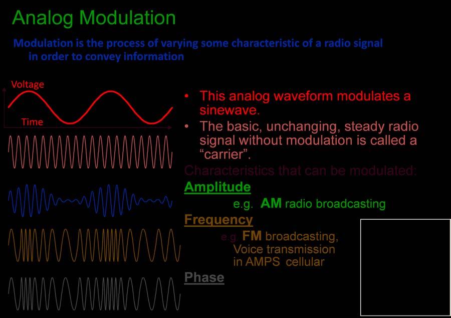
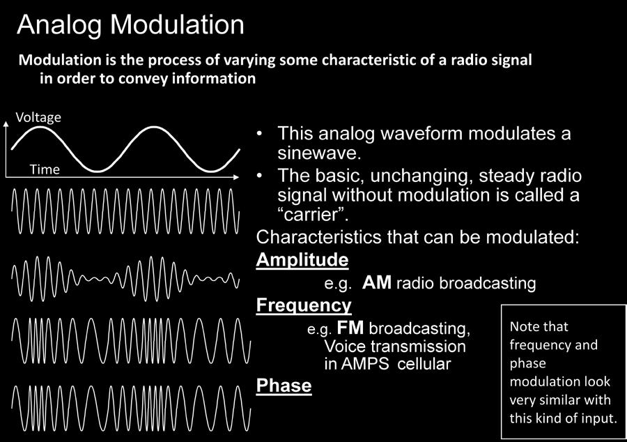
Modulation is the process of impressing a low-frequency information signal (baseband signal) onto a higher frequency carrier signal
|
|
|
- Alexina Norman
- 5 years ago
- Views:
Transcription


1 Modulation is the process of impressing a low-frequency information signal (baseband signal) onto a higher frequency carrier signal Modulation is a process of mixing a signal with a sinusoid to produce a new signal. This new signal, conceivably, will have certain benefits of an un-modulated signal, especially during transmission. If we look at a general function for a sinusoid: f(t) = Asin(ωt + ϕ) we can see that this sinusoid has 3 parameters that can be altered, to affect the shape of the graph. The first term, A, is called the magnitude, or amplitude of the sinusoid. The next term, ω is known as the frequency, and the last term, ϕ is known as the phase angle. All 3 parameters can be altered to transmit data. The sinusoidal signal that is used in the modulation is known as the carrier signal, or simply "the carrier". The signal that is used in modulating the carrier signal(or sinusoidal signal) is known as the "data signal" or the "message signal". It is important to notice that a simple sinusoidal carrier contains no information of its own. In other words we can say that modulation is used because the some data signals are not always suitable for direct transmission, but the modulated signal may be more suitable. Types of modulations Analog modulations Digital modulations AM PM FM ASK FSK PSK
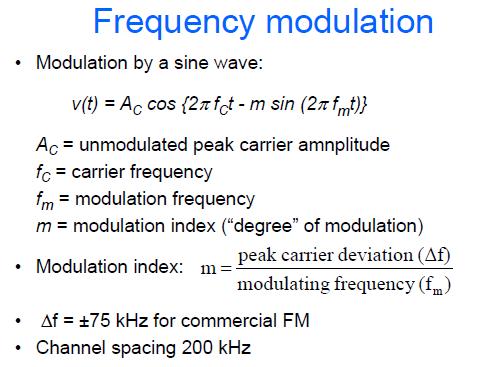
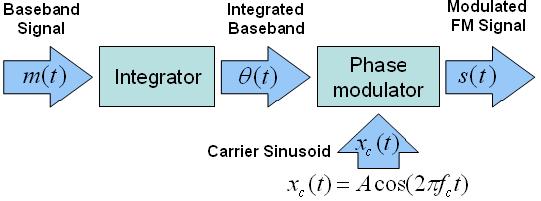
 Frequency modulation is the process of varying the frequency of a carrier wave in proportion to the amplitude of a baseband")
 Phase modulation is the process of varying the Phase of a carrier wave in proportion to the amplitude of a baseband The")

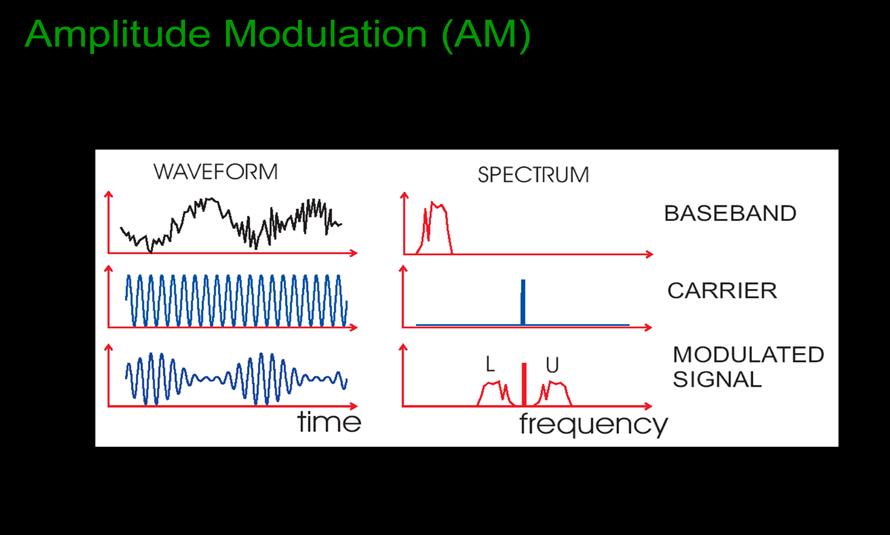
2 Remember the radio spectrum: Note:- Amplitude Modulation (AM) Amplitude modulation is the process of varying the amplitude of a carrier wave in proportion to the amplitude of a baseband signal. The frequency of the carrier remains constant Frequency Modulation (FM) Frequency modulation is the process of varying the frequency of a carrier wave in proportion to the amplitude of a baseband signal. The amplitude of the carrier remains constant Phase Modulation (PM) Phase modulation is the process of varying the Phase of a carrier wave in proportion to the amplitude of a baseband signal. The amplitude of the carrier remains constant In this type of modulation, A c, w c are kept constant. The phase angle ϕ of the carrier wave is varied according to the modulating wave. The common name for "phase modulation" and "frequency modulation" is "angle modulation". The digital transmission of analog signals involves pulse modulation. In analog pulse modulation, time is represented in discrete form. In digital pulse modulation, both time and signal amplitude are represented in discrete form. Note:- FM and PM closely related AM radio band ~500 to 1600 khz, FM radio band 88 to 108 MHz


 channels on the radio at any time, each with a given frequency: 100.1MHz, 102.5MHz etc.")
 over a bandpass (or")
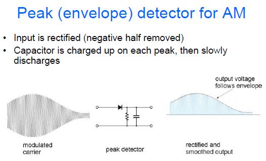
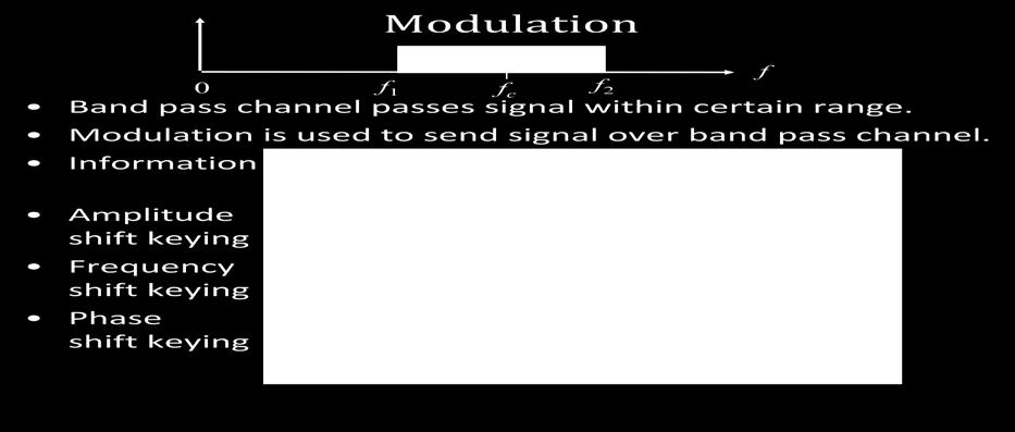
3 Why use modulation? Carrying one signal on another - uses carrier Modulated carrier transmitted Problems with transmitting baseband signals Antennas difficult at low frequencies Noise and interference at low frequencies Can t share with others Easier to transmit carrier at higher frequency Can choose convenient frequency Antennas can be smaller May be useful propagation effects Fractional bandwidth much smaller Antennas and other components easier to design Can have many frequency channels Application: - Think about your car radio. There are more than a dozen (or so) channels on the radio at any time, each with a given frequency: 100.1MHz, 102.5MHz etc... Each channel gets a certain range (usually about 0.2MHz), and the entire station gets transmitted over that range. Modulation makes it all possible, because it allows us to send voice and music (which are essential baseband signals) over a bandpass (or "Broadband") channel. Amplitude modulation (AM) Simplest case of AM is where carrier is just turned on or off. Continuous amplitude modulation (eg AM radio) Information contained in the envelope shape
4
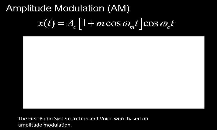
 m must be between 0 and 1 If m > 1 get over modulation (bad")
5 Modulation by a sine wave: v(t) = AC cos (2π fct) {1 + m cos (2π fmt)} AC = un modulated peak carrier amplitude fc = carrier frequency fm = modulation frequency m = modulation index ( degree of modulation) m must be between 0 and 1 If m > 1 get over modulation (bad distortion)
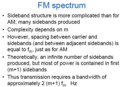
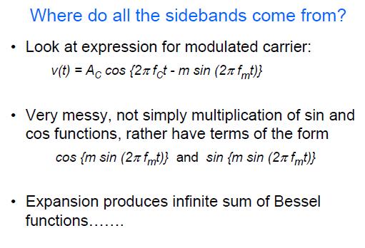
6 AM spectrum Modulation produces two new components called sidebands, at frequencies above and below the carrier For a fully modulated carrier (m=1), 2/3 of the power is in the carrier, the rest in the sidebands The spacing in frequency between carrier and sidebands is equal to fm (the modulating frequency) Hence a bandwidth of 2 x fm is required to transmit the modulated carrier With a more complicated modulating signal (e.g. voice) the sidebands will be extended, so that a bandwidth of twice the highest modulating frequency present is required Where do the sidebands come from?
7
8
9
10 The basic components of a phase-locked loop (PLL) are a stable reference oscillator, a phase detector, a frequency divider, a voltage-controlled oscillator (VCO), amplifiers, and filters. The following figure shows a simplified PLL block diagram. PLLs work by comparing the generated signal phase to the reference oscillator signal phase and then using the difference to adjust the generated signal. To compare the two waves, both signals must be of the same frequency. The frequency divider is used to divide down the generated signal. Because the frequency divider can divide down only an integer number of times, the generated signal must be an integer multiple of the reference oscillator signal. The phase detector returns a voltage depending on the phase difference between the two waves. This voltage is amplified, filtered, and then fed into the VCO. The VCO adjusts the signal it outputs based on this voltage.
11
COMMUNICATION SYSTEMS-II (In continuation with Part-I)
") MODULATING A SIGNAL COMMUNICATION SYSTEMS-II (In continuation with Part-I) TRANSMITTING SIGNALS : In order to transmit the original low frequency baseband message efficiently over long distances, the signal
MODULATING A SIGNAL COMMUNICATION SYSTEMS-II (In continuation with Part-I) TRANSMITTING SIGNALS : In order to transmit the original low frequency baseband message efficiently over long distances, the signal
EE470 Electronic Communication Theory Exam II
 EE470 Electronic Communication Theory Exam II Open text, closed notes. For partial credit, you must show all formulas in symbolic form and you must work neatly!!! Date: November 6, 2013 Name: 1. [16%]
UNIT-2 Angle Modulation System
 UNIT-2 Angle Modulation System Introduction There are three parameters of a carrier that may carry information: Amplitude Frequency Phase Frequency Modulation Power in an FM signal does not vary with modulation
Speech, music, images, and video are examples of analog signals. Each of these signals is characterized by its bandwidth, dynamic range, and the
 Speech, music, images, and video are examples of analog signals. Each of these signals is characterized by its bandwidth, dynamic range, and the nature of the signal. For instance, in the case of audio
Code No: R Set No. 1
 Code No: R05220405 Set No. 1 II B.Tech II Semester Regular Examinations, Apr/May 2007 ANALOG COMMUNICATIONS ( Common to Electronics & Communication Engineering and Electronics & Telematics) Time: 3 hours
EE 460L University of Nevada, Las Vegas ECE Department
 EE 460L PREPARATION 1- ASK Amplitude shift keying - ASK - in the context of digital communications is a modulation process which imparts to a sinusoid two or more discrete amplitude levels. These are related
Master Degree in Electronic Engineering
 Master Degree in Electronic Engineering Analog and telecommunication electronic course (ATLCE-01NWM) Miniproject: Baseband signal transmission techniques Name: LI. XINRUI E-mail: s219989@studenti.polito.it
two computers. 2- Providing a channel between them for transmitting and receiving the signals through it.
 1. Introduction: Communication is the process of transmitting the messages that carrying information, where the two computers can be communicated with each other if the two conditions are available: 1-
Amplitude Modulation Chapter 2. Modulation process
 Question 1 Modulation process Modulation is the process of translation the baseband message signal to bandpass (modulated carrier) signal at frequencies that are very high compared to the baseband frequencies.
TSEK02: Radio Electronics Lecture 2: Modulation (I) Ted Johansson, EKS, ISY
 Ted Johansson, EKS, ISY") TSEK02: Radio Electronics Lecture 2: Modulation (I) Ted Johansson, EKS, ISY An Overview of Modulation Techniques: chapter 3.1 3.3.1 2 Introduction (3.1) Analog Modulation Amplitude Modulation Phase and
TSEK02: Radio Electronics Lecture 2: Modulation (I) Ted Johansson, EKS, ISY An Overview of Modulation Techniques: chapter 3.1 3.3.1 2 Introduction (3.1) Analog Modulation Amplitude Modulation Phase and
Twelve voice signals, each band-limited to 3 khz, are frequency -multiplexed using 1 khz guard bands between channels and between the main carrier
 Twelve voice signals, each band-limited to 3 khz, are frequency -multiplexed using 1 khz guard bands between channels and between the main carrier and the first channel. The modulation of the main carrier
ELEC3242 Communications Engineering Laboratory Frequency Shift Keying (FSK)
") ELEC3242 Communications Engineering Laboratory 1 ---- Frequency Shift Keying (FSK) 1) Frequency Shift Keying Objectives To appreciate the principle of frequency shift keying and its relationship to analogue
ELEC3242 Communications Engineering Laboratory 1 ---- Frequency Shift Keying (FSK) 1) Frequency Shift Keying Objectives To appreciate the principle of frequency shift keying and its relationship to analogue
Elements of Communication System Channel Fig: 1: Block Diagram of Communication System Terminology in Communication System
 Content:- Fundamentals of Communication Engineering : Elements of a Communication System, Need of modulation, electromagnetic spectrum and typical applications, Unit V (Communication terminologies in communication
TSEK02: Radio Electronics Lecture 2: Modulation (I) Ted Johansson, EKS, ISY
 Ted Johansson, EKS, ISY") TSEK02: Radio Electronics Lecture 2: Modulation (I) Ted Johansson, EKS, ISY 2 Basic Definitions Time and Frequency db conversion Power and dbm Filter Basics 3 Filter Filter is a component with frequency
TSEK02: Radio Electronics Lecture 2: Modulation (I) Ted Johansson, EKS, ISY 2 Basic Definitions Time and Frequency db conversion Power and dbm Filter Basics 3 Filter Filter is a component with frequency
Outline. Communications Engineering 1
 Outline Introduction Signal, random variable, random process and spectra Analog modulation Analog to digital conversion Digital transmission through baseband channels Signal space representation Optimal
College of information Technology Department of Information Networks Telecommunication & Networking I Chapter 5. Analog Transmission
 Analog Transmission 5.1 DIGITAL-TO-ANALOG CONVERSION Digital-to-analog conversion is the process of changing one of the characteristics of an analog signal based on the information in digital data. The
Lecture 6. Angle Modulation and Demodulation
 Lecture 6 and Demodulation Agenda Introduction to and Demodulation Frequency and Phase Modulation Angle Demodulation FM Applications Introduction The other two parameters (frequency and phase) of the carrier
EE 400L Communications. Laboratory Exercise #7 Digital Modulation
 EE 400L Communications Laboratory Exercise #7 Digital Modulation Department of Electrical and Computer Engineering University of Nevada, at Las Vegas PREPARATION 1- ASK Amplitude shift keying - ASK - in
Signals and Systems Lecture 9 Communication Systems Frequency-Division Multiplexing and Frequency Modulation (FM)
") Signals and Systems Lecture 9 Communication Systems Frequency-Division Multiplexing and Frequency Modulation (FM) April 11, 2008 Today s Topics 1. Frequency-division multiplexing 2. Frequency modulation
Signals and Systems Lecture 9 Communication Systems Frequency-Division Multiplexing and Frequency Modulation (FM) April 11, 2008 Today s Topics 1. Frequency-division multiplexing 2. Frequency modulation
Wireless Communication Fading Modulation
 EC744 Wireless Communication Fall 2008 Mohamed Essam Khedr Department of Electronics and Communications Wireless Communication Fading Modulation Syllabus Tentatively Week 1 Week 2 Week 3 Week 4 Week 5
Communication Channels
 Communication Channels wires (PCB trace or conductor on IC) optical fiber (attenuation 4dB/km) broadcast TV (50 kw transmit) voice telephone line (under -9 dbm or 110 µw) walkie-talkie: 500 mw, 467 MHz
Charan Langton, Editor
 Charan Langton, Editor SIGNAL PROCESSING & SIMULATION NEWSLETTER Baseband, Passband Signals and Amplitude Modulation The most salient feature of information signals is that they are generally low frequency.
Analog Communication.
 Analog Communication Vishnu N V Tele is Greek for at a distance, and Communicare is latin for to make common. Telecommunication is the process of long distance communications. Early telecommunications
ECE513 RF Design for Wireless
 1 ECE513 RF Design for Wireless MODULE 1 RF Systems LECTURE 1 Modulation Techniques Chapter 1, Sections 1.1 1.3 Professor Michael Steer http://www4.ncsu.edu/~mbs 2 Module 1: RF Systems Amplifiers, Mixers
AM Limitations. Amplitude Modulation II. DSB-SC Modulation. AM Modifications
 Lecture 6: Amplitude Modulation II EE 3770: Communication Systems AM Limitations AM Limitations DSB-SC Modulation SSB Modulation VSB Modulation Lecture 6 Amplitude Modulation II Amplitude modulation is
Amplitude Modulation, II
 Amplitude Modulation, II Single sideband modulation (SSB) Vestigial sideband modulation (VSB) VSB spectrum Modulator and demodulator NTSC TV signsals Quadrature modulation Spectral efficiency Modulator
Angle Modulated Systems
 Angle Modulated Systems Angle of carrier signal is changed in accordance with instantaneous amplitude of modulating signal. Two types Frequency Modulation (FM) Phase Modulation (PM) Use Commercial radio
Amplitude Modulation II
 Lecture 6: Amplitude Modulation II EE 3770: Communication Systems Lecture 6 Amplitude Modulation II AM Limitations DSB-SC Modulation SSB Modulation VSB Modulation Multiplexing Mojtaba Vaezi 6-1 Contents
AC LAB ECE-D ecestudy.wordpress.com
 PART B EXPERIMENT NO: 1 AIM: PULSE AMPLITUDE MODULATION (PAM) & DEMODULATION DATE: To study Pulse Amplitude modulation and demodulation process with relevant waveforms. APPARATUS: 1. Pulse amplitude modulation
Chapter 3: Analog Modulation Cengage Learning Engineering. All Rights Reserved.
 Contemporary Communication Systems using MATLAB Chapter 3: Analog Modulation 2013 Cengage Learning Engineering. All Rights Reserved. 3.1 Preview In this chapter we study analog modulation & demodulation,
List of Figures. Sr. no.
 List of Figures Sr. no. Topic No. Topic 1 1.3.1 Angle Modulation Graphs 11 2 2.1 Resistor 13 3 3.1 Block Diagram of The FM Transmitter 15 4 4.2 Basic Diagram of FM Transmitter 17 5 4.3 Circuit Diagram
Principles of Communications ECS 332
 Principles of Communications ECS 332 Asst. Prof. Dr. Prapun Suksompong prapun@siit.tu.ac.th 5. Angle Modulation Office Hours: BKD, 6th floor of Sirindhralai building Wednesday 4:3-5:3 Friday 4:3-5:3 Example
Communication Systems Lab
 LAB MANUAL Communication Systems Lab (EE-226-F) Prepared by: Varun Sharma (Lab In-charge) Dayal C. Sati (Faculty In-charge) B R C M CET BAHAL DEPARTMENT OF ELECTRONICS & COMMUNICATION ENGINEERING Page
B.Tech II Year II Semester (R13) Supplementary Examinations May/June 2017 ANALOG COMMUNICATION SYSTEMS (Electronics and Communication Engineering)
 Supplementary Examinations May/June 2017 ANALOG COMMUNICATION SYSTEMS (Electronics and Communication Engineering)") Code: 13A04404 R13 B.Tech II Year II Semester (R13) Supplementary Examinations May/June 2017 ANALOG COMMUNICATION SYSTEMS (Electronics and Communication Engineering) Time: 3 hours Max. Marks: 70 PART A
Code: 13A04404 R13 B.Tech II Year II Semester (R13) Supplementary Examinations May/June 2017 ANALOG COMMUNICATION SYSTEMS (Electronics and Communication Engineering) Time: 3 hours Max. Marks: 70 PART A
ELEC3242 Communications Engineering Laboratory Amplitude Modulation (AM)
") ELEC3242 Communications Engineering Laboratory 1 ---- Amplitude Modulation (AM) 1. Objectives 1.1 Through this the laboratory experiment, you will investigate demodulation of an amplitude modulated (AM)
ELEC3242 Communications Engineering Laboratory 1 ---- Amplitude Modulation (AM) 1. Objectives 1.1 Through this the laboratory experiment, you will investigate demodulation of an amplitude modulated (AM)
COMM 601: Modulation I
 Prof. Ahmed El-Mahdy, Communications Department The German University in Cairo Text Books [1] Couch, Digital and Analog Communication Systems, 7 th edition, Prentice Hall, 2007. [2] Simon Haykin, Communication
Mobile Communication An overview Lesson 03 Introduction to Modulation Methods
 Mobile Communication An overview Lesson 03 Introduction to Modulation Methods Oxford University Press 2007. All rights reserved. 1 Modulation The process of varying one signal, called carrier, according
 Modulations Analog Modulations Amplitude modulation (AM) Linear modulation Frequency modulation (FM) Phase modulation (PM) cos Angle modulation FM PM Digital Modulations ASK FSK PSK MSK MFSK QAM PAM Etc.
Universitas Sumatera Utara
 Amplitude Shift Keying & Frequency Shift Keying Aim: To generate and demodulate an amplitude shift keyed (ASK) signal and a binary FSK signal. Intro to Generation of ASK Amplitude shift keying - ASK -
ECE5713 : Advanced Digital Communications
 ECE5713 : Advanced Digital Communications Bandpass Modulation MPSK MASK, OOK MFSK 04-May-15 Advanced Digital Communications, Spring-2015, Week-8 1 In-phase and Quadrature (I&Q) Representation Any bandpass
EE4512 Analog and Digital Communications Chapter 6. Chapter 6 Analog Modulation and Demodulation
 Chapter 6 Analog Modulation and Demodulation Chapter 6 Analog Modulation and Demodulation Amplitude Modulation Pages 306-309 309 The analytical signal for double sideband, large carrier amplitude modulation
3.1 Introduction to Modulation
 Haberlesme Sistemlerine Giris (ELE 361) 9 Eylul 2017 TOBB Ekonomi ve Teknoloji Universitesi, Guz 2017-18 Dr. A. Melda Yuksel Turgut & Tolga Girici Lecture Notes Chapter 3 Amplitude Modulation Speech, music,
Amplitude Modulated Systems
 Amplitude Modulated Systems Communication is process of establishing connection between two points for information exchange. Channel refers to medium through which message travels e.g. wires, links, or
AM, PM and FM mo m dula l ti t o i n
 AM, PM and FM modulation What is amplitude modulation In order that a radio signal can carry audio or other information for broadcasting or for two way radio communication, it must be modulated or changed
EXPERIMENT 2: Frequency Shift Keying (FSK)
") EXPERIMENT 2: Frequency Shift Keying (FSK) 1) OBJECTIVE Generation and demodulation of a frequency shift keyed (FSK) signal 2) PRELIMINARY DISCUSSION In FSK, the frequency of a carrier signal is modified
EXPERIMENT 2: Frequency Shift Keying (FSK) 1) OBJECTIVE Generation and demodulation of a frequency shift keyed (FSK) signal 2) PRELIMINARY DISCUSSION In FSK, the frequency of a carrier signal is modified
Keysight Technologies
 Keysight Technologies Generating Signals Basic CW signal Block diagram Applications Analog Modulation Types of analog modulation Block diagram Applications Digital Modulation Overview of IQ modulation
EE3723 : Digital Communications
 EE3723 : Digital Communications Week 8-9: Bandpass Modulation MPSK MASK, OOK MFSK 04-May-15 Muhammad Ali Jinnah University, Islamabad - Digital Communications - EE3723 1 In-phase and Quadrature (I&Q) Representation
Data Conversion Circuits & Modulation Techniques. Subhasish Chandra Assistant Professor Department of Physics Institute of Forensic Science, Nagpur
 Data Conversion Circuits & Modulation Techniques Subhasish Chandra Assistant Professor Department of Physics Institute of Forensic Science, Nagpur Data Conversion Circuits 2 Digital systems are being used
Internal Examination I Answer Key DEPARTMENT OF CSE & IT. Semester: III Max.Marks: 100
 NH 67, Karur Trichy Highways, Puliyur C.F, 639 114 Karur District Internal Examination I Answer Key DEPARTMENT OF CSE & IT Branch & Section: II CSE & IT Date & Time: 06.08.15 & 3 Hours Semester: III Max.Marks:
Digital Modulation Lecture 01. Review of Analogue Modulation Introduction to Digital Modulation Techniques Richard Harris
 Digital Modulation Lecture 01 Review of Analogue Modulation Introduction to Digital Modulation Techniques Richard Harris Objectives You will be able to: Classify the various approaches to Analogue Modulation
CHAPTER 2 DIGITAL MODULATION
 2.1 INTRODUCTION CHAPTER 2 DIGITAL MODULATION Referring to Equation (2.1), if the information signal is digital and the amplitude (lv of the carrier is varied proportional to the information signal, a
Objectives. Presentation Outline. Digital Modulation Lecture 01
 Digital Modulation Lecture 01 Review of Analogue Modulation Introduction to Digital Modulation Techniques Richard Harris Objectives You will be able to: Classify the various approaches to Analogue Modulation
(b) What are the differences between FM and PM? (c) What are the differences between NBFM and WBFM? [9+4+3]
![(b) What are the differences between FM and PM? (c) What are the differences between NBFM and WBFM? [9+4+3]](/thumbs/85/91561193.jpg "(b) What are the differences between FM and PM? (c) What are the differences between NBFM and WBFM? [9+4+3]") Code No: RR220401 Set No. 1 1. (a) The antenna current of an AM Broadcast transmitter is 10A, if modulated to a depth of 50% by an audio sine wave. It increases to 12A as a result of simultaneous modulation
Code No: RR220401 Set No. 1 1. (a) The antenna current of an AM Broadcast transmitter is 10A, if modulated to a depth of 50% by an audio sine wave. It increases to 12A as a result of simultaneous modulation
Problems from the 3 rd edition
 (2.1-1) Find the energies of the signals: a) sin t, 0 t π b) sin t, 0 t π c) 2 sin t, 0 t π d) sin (t-2π), 2π t 4π Problems from the 3 rd edition Comment on the effect on energy of sign change, time shifting
 UNIT I FUNDAMENTALS OF ANALOG COMMUNICATION Introduction In the Microbroadcasting services, a reliable radio communication system is of vital importance. The swiftly moving operations of modern communities
Amplitude Modulation. Ahmad Bilal
 Amplitude Modulation Ahmad Bilal 5-2 ANALOG AND DIGITAL Analog-to-analog conversion is the representation of analog information by an analog signal. Topics discussed in this section: Amplitude Modulation
Experiment No. 3 Pre-Lab Phase Locked Loops and Frequency Modulation
 Experiment No. 3 Pre-Lab Phase Locked Loops and Frequency Modulation The Pre-Labs are informational and although they follow the procedures in the experiment, they are to be completed outside of the laboratory.
Chapter-15. Communication systems -1 mark Questions
 Chapter-15 Communication systems -1 mark Questions 1) What are the three main units of a Communication System? 2) What is meant by Bandwidth of transmission? 3) What is a transducer? Give an example. 4)
DT Filters 2/19. Atousa Hajshirmohammadi, SFU
 1/19 ENSC380 Lecture 23 Objectives: Signals and Systems Fourier Analysis: Discrete Time Filters Analog Communication Systems Double Sideband, Sub-pressed Carrier Modulation (DSBSC) Amplitude Modulation
EXPERIMENT WISE VIVA QUESTIONS
 EXPERIMENT WISE VIVA QUESTIONS Pulse Code Modulation: 1. Draw the block diagram of basic digital communication system. How it is different from analog communication system. 2. What are the advantages of
AM and FM MODULATION Lecture 5&6
 AM and FM MODULATION Lecture 5&6 Ir. Muhamad Asvial, MEng., PhD Center for Information and Communication Engineering Research Electrical Engineering Department University of Indonesia Kampus UI Depok,
Exercise 2: FM Detection With a PLL
 Phase-Locked Loop Analog Communications Exercise 2: FM Detection With a PLL EXERCISE OBJECTIVE When you have completed this exercise, you will be able to explain how the phase detector s input frequencies
EE228 Applications of Course Concepts. DePiero
 EE228 Applications of Course Concepts DePiero Purpose Describe applications of concepts in EE228. Applications may help students recall and synthesize concepts. Also discuss: Some advanced concepts Highlight
Department of Electronic and Information Engineering. Communication Laboratory
 Department of Electronic and Information Engineering Communication Laboratory Frequency Shift Keying (FSK) & Differential Phase Shift Keying (DPSK) & Differential Quadrature Phase Shift Keying (DQPSK)
Exercise 1: Amplitude Modulation
 AM Transmission Analog Communications Exercise 1: Amplitude Modulation EXERCISE OBJECTIVE When you have completed this exercise, you will be able to describe the generation of amplitudemodulated signals
CHETTINAD COLLEGE OF ENGINEERING & TECHNOLOGY NH-67, TRICHY MAIN ROAD, PULIYUR, C.F , KARUR DT.
 CHETTINAD COLLEGE OF ENGINEERING & TECHNOLOGY NH-67, TRICHY MAIN ROAD, PULIYUR, C.F. 639 114, KARUR DT. DEPARTMENT OF ELECTRONICS AND COMMUNICATION ENGINEERING COURSE MATERIAL Subject Name: Analog & Digital
PRODUCT DEMODULATION - SYNCHRONOUS & ASYNCHRONOUS
 PRODUCT DEMODULATION - SYNCHRONOUS & ASYNCHRONOUS INTRODUCTION...98 frequency translation...98 the process...98 interpretation...99 the demodulator...100 synchronous operation: ω 0 = ω 1...100 carrier
EE-4022 Experiment 3 Frequency Modulation (FM)
") EE-4022 MILWAUKEE SCHOOL OF ENGINEERING 2015 Page 3-1 Student Objectives: EE-4022 Experiment 3 Frequency Modulation (FM) In this experiment the student will use laboratory modules including a Voltage-Controlled
EE-4022 MILWAUKEE SCHOOL OF ENGINEERING 2015 Page 3-1 Student Objectives: EE-4022 Experiment 3 Frequency Modulation (FM) In this experiment the student will use laboratory modules including a Voltage-Controlled
4.1 REPRESENTATION OF FM AND PM SIGNALS An angle-modulated signal generally can be written as
 1 In frequency-modulation (FM) systems, the frequency of the carrier f c is changed by the message signal; in phase modulation (PM) systems, the phase of the carrier is changed according to the variations
Basic Concepts in Data Transmission
 Basic Concepts in Data Transmission EE450: Introduction to Computer Networks Professor A. Zahid A.Zahid-EE450 1 Data and Signals Data is an entity that convey information Analog Continuous values within
Department of Electronic and Information Engineering. Communication Laboratory. Phase Shift Keying (PSK) & Quadrature Phase Shift Keying (QPSK)
 & Quadrature Phase Shift Keying (QPSK)") Department of Electronic and Information Engineering Communication Laboratory Phase Shift Keying (PSK) & Quadrature Phase Shift Keying (QPSK) Objectives To familiar with the concept of describing phase
Department of Electronic and Information Engineering Communication Laboratory Phase Shift Keying (PSK) & Quadrature Phase Shift Keying (QPSK) Objectives To familiar with the concept of describing phase
Lecture 15: Introduction to Mixers
 EECS 142 Lecture 15: Introduction to Mixers Prof. Ali M. Niknejad University of California, Berkeley Copyright c 2005 by Ali M. Niknejad A. M. Niknejad University of California, Berkeley EECS 142 Lecture
Technician License Course Chapter 2. Lesson Plan Module 3 Modulation and Bandwidth
 Technician License Course Chapter 2 Lesson Plan Module 3 Modulation and Bandwidth The Basic Radio Station What Happens During Radio Communication? Transmitting (sending a signal): Information (voice, data,
cosω t Y AD 532 Analog Multiplier Board EE18.xx Fig. 1 Amplitude modulation of a sine wave message signal
 University of Saskatchewan EE 9 Electrical Engineering Laboratory III Amplitude and Frequency Modulation Objectives: To observe the time domain waveforms and spectra of amplitude modulated (AM) waveforms
COMMUNICATION SYSTEMS NCERT
 Exemplar Problems Physics Chapter Fifteen COMMUNCATON SYSTEMS MCQ 151 Three waves A, B and C of frequencies 1600 khz, 5 MHz and 60 MHz, respectively are to be transmitted from one place to another Which
An Investigation into the Effects of Sampling on the Loop Response and Phase Noise in Phase Locked Loops
 An Investigation into the Effects of Sampling on the Loop Response and Phase oise in Phase Locked Loops Peter Beeson LA Techniques, Unit 5 Chancerygate Business Centre, Surbiton, Surrey Abstract. The majority
ENSC327 Communication Systems 27: Digital Bandpass Modulation. (Ch. 7) Jie Liang School of Engineering Science Simon Fraser University
 Jie Liang School of Engineering Science Simon Fraser University") ENSC37 Communication Systems 7: Digital Bandpass Modulation (Ch. 7) Jie Liang School of Engineering Science Simon Fraser University 1 Outline 7.1 Preliminaries 7. Binary Amplitude-Shift Keying (BASK) 7.3
ENSC37 Communication Systems 7: Digital Bandpass Modulation (Ch. 7) Jie Liang School of Engineering Science Simon Fraser University 1 Outline 7.1 Preliminaries 7. Binary Amplitude-Shift Keying (BASK) 7.3
Chapter 3. Question Mar No
 Chapter 3 Sr Question Mar No k. 1 Write any two drawbacks of TRF radio receiver 1. Instability due to oscillatory nature of RF amplifier.. Variation in bandwidth over tuning range. 3. Insufficient selectivity
Lecture 10. Digital Modulation
 Digital Modulation Lecture 10 On-Off keying (OOK), or amplitude shift keying (ASK) Phase shift keying (PSK), particularly binary PSK (BPSK) Frequency shift keying Typical spectra Modulation/demodulation
Experiment 7: Frequency Modulation and Phase Locked Loops
 Experiment 7: Frequency Modulation and Phase Locked Loops Frequency Modulation Background Normally, we consider a voltage wave form with a fixed frequency of the form v(t) = V sin( ct + ), (1) where c
Operating Manual Ver 1.1
 Frequency Modulation and Demodulation Trainer ST2203 Operating Manual Ver 1.1 An ISO 9001 : 2000 company 94-101, Electronic Complex Pardesipura, Indore- 452010, India Tel : 91-731- 2570301/02, 4211100
PLL EXERCISE. R3 16k C3. 2π π 0 π 2π
 PLL EXERCISE Φ in (S) PHASE DETECTOR + Kd - V d (S) R1 R2 C2 220k 10k 10 nf Φ o (S) VCO Kv S V c (S) R3 16k C3 1 nf V dem (S) VCO Characteristics Phase Detector Characteristics V d ave F o 150k +5V (H
1/14. Signal. Surasak Sanguanpong Last updated: 11 July Signal 1/14
 1/14 Signal Surasak Sanguanpong nguan@ku.ac.th http://www.cpe.ku.ac.th/~nguan Last updated: 11 July 2000 Signal 1/14 Transmission structure 2/14 Transmitter/ Receiver Medium Amplifier/ Repeater Medium
EE 318 Electronic Design Lab. Hi-fi Audio Transmitter from first principles
 EE 318 Electronic Design Lab Hi-fi Audio Transmitter from first principles Supervised by Prof. Jayanta Mukherjee Prof. Dipankar Prof. L. Subramaniam By Group-9 Vipul Chaudhary (08d07039) Vineet Raj (08d07040)
Fourier Transform Analysis of Signals and Systems
 Fourier Transform Analysis of Signals and Systems Ideal Filters Filters separate what is desired from what is not desired In the signals and systems context a filter separates signals in one frequency
Experiment One: Generating Frequency Modulation (FM) Using Voltage Controlled Oscillator (VCO)
 Using Voltage Controlled Oscillator (VCO)") Experiment One: Generating Frequency Modulation (FM) Using Voltage Controlled Oscillator (VCO) Modified from original TIMS Manual experiment by Mr. Faisel Tubbal. Objectives 1) Learn about VCO and how
Experiment One: Generating Frequency Modulation (FM) Using Voltage Controlled Oscillator (VCO) Modified from original TIMS Manual experiment by Mr. Faisel Tubbal. Objectives 1) Learn about VCO and how
Electronics Interview Questions
 Electronics Interview Questions 1. What is Electronic? The study and use of electrical devices that operate by controlling the flow of electrons or other electrically charged particles. 2. What is communication?
page 7.51 Chapter 7, sections , pp Angle Modulation No Modulation (t) =2f c t + c Instantaneous Frequency 2 dt dt No Modulation
 =2f c t + c Instantaneous Frequency 2 dt dt No Modulation") page 7.51 Chapter 7, sections 7.1-7.14, pp. 322-368 Angle Modulation s(t) =A c cos[(t)] No Modulation (t) =2f c t + c s(t) =A c cos[2f c t + c ] Instantaneous Frequency f i (t) = 1 d(t) 2 dt or w i (t)
page 7.51 Chapter 7, sections 7.1-7.14, pp. 322-368 Angle Modulation s(t) =A c cos[(t)] No Modulation (t) =2f c t + c s(t) =A c cos[2f c t + c ] Instantaneous Frequency f i (t) = 1 d(t) 2 dt or w i (t)
Analog and Telecommunication Electronics
 Politecnico di Torino Electronic Eng. Master Degree Analog and Telecommunication Electronics C5 - Synchronous demodulation» AM and FM demodulation» Coherent demodulation» Tone decoders AY 2015-16 19/03/2016-1
Local Oscillator Phase Noise and its effect on Receiver Performance C. John Grebenkemper
 Watkins-Johnson Company Tech-notes Copyright 1981 Watkins-Johnson Company Vol. 8 No. 6 November/December 1981 Local Oscillator Phase Noise and its effect on Receiver Performance C. John Grebenkemper All
RFID Systems: Radio Architecture
 RFID Systems: Radio Architecture 1 A discussion of radio architecture and RFID. What are the critical pieces? Familiarity with how radio and especially RFID radios are designed will allow you to make correct
Experiment 02: Amplitude Modulation
 ECE316, Experiment 02, 2017 Communications Lab, University of Toronto Experiment 02: Amplitude Modulation Bruno Korst - bkf@comm.utoronto.ca Abstract In this second laboratory experiment, you will see
1. Explain how Doppler direction is identified with FMCW radar. Fig Block diagram of FM-CW radar. f b (up) = f r - f d. f b (down) = f r + f d
 = f r - f d. f b (down) = f r + f d") 1. Explain how Doppler direction is identified with FMCW radar. A block diagram illustrating the principle of the FM-CW radar is shown in Fig. 4.1.1 A portion of the transmitter signal acts as the reference
1. Explain how Doppler direction is identified with FMCW radar. A block diagram illustrating the principle of the FM-CW radar is shown in Fig. 4.1.1 A portion of the transmitter signal acts as the reference
Lecture (01) Data Transmission (I)
 Data Transmission (I)") Agenda Lecture (01) Data Transmission (I) The objective Transmission terminologies Bandwidth and data rate Dr. Ahmed ElShafee ١ Dr. Ahmed ElShafee, ACU Spring 2016, Data Communication ٢ Dr. Ahmed ElShafee,
Agenda Lecture (01) Data Transmission (I) The objective Transmission terminologies Bandwidth and data rate Dr. Ahmed ElShafee ١ Dr. Ahmed ElShafee, ACU Spring 2016, Data Communication ٢ Dr. Ahmed ElShafee,
Signal Characteristics
 Data Transmission The successful transmission of data depends upon two factors:» The quality of the transmission signal» The characteristics of the transmission medium Some type of transmission medium
Final Exam Solutions June 7, 2004
 Name: Final Exam Solutions June 7, 24 ECE 223: Signals & Systems II Dr. McNames Write your name above. Keep your exam flat during the entire exam period. If you have to leave the exam temporarily, close
Analysis of Phase Noise Profile of a 1.1 GHz Phase-locked Loop
 Analysis of Phase Noise Profile of a 1.1 GHz Phase-locked Loop J. Handique, Member, IAENG and T. Bezboruah, Member, IAENG 1 Abstract We analyzed the phase noise of a 1.1 GHz phaselocked loop system for
Technician License Course Chapter 3 Types of Radios and Radio Circuits. Module 7
 Technician License Course Chapter 3 Types of Radios and Radio Circuits Module 7 Radio Block Diagrams Radio Circuits can be shown as functional blocks connected together. Knowing the description of common
Chapter 7. Multiple Division Techniques
 Chapter 7 Multiple Division Techniques 1 Outline Frequency Division Multiple Access (FDMA) Division Multiple Access (TDMA) Code Division Multiple Access (CDMA) Comparison of FDMA, TDMA, and CDMA Walsh
Mobile & Wireless Networking. Lecture 2: Wireless Transmission (2/2)
") 192620010 Mobile & Wireless Networking Lecture 2: Wireless Transmission (2/2) [Schiller, Section 2.6 & 2.7] [Reader Part 1: OFDM: An architecture for the fourth generation] Geert Heijenk Outline of Lecture
192620010 Mobile & Wireless Networking Lecture 2: Wireless Transmission (2/2) [Schiller, Section 2.6 & 2.7] [Reader Part 1: OFDM: An architecture for the fourth generation] Geert Heijenk Outline of Lecture