QUICK START GUIDE FOR DEMONSTRATION CIRCUIT 678A 40MHZ TO 900MHZ DIRECT CONVERSION QUADRATURE DEMODULATOR
|
|
|
- Dorcas Thompson
- 5 years ago
- Views:
Transcription
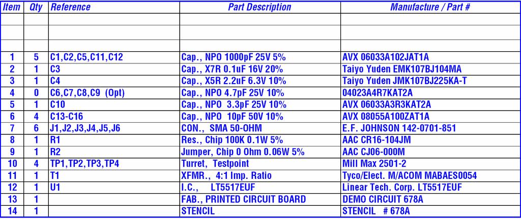
1 DESCRIPTION QUICK START GUIDE FOR DEMONSTRATION CIRCUIT 678A LT5517 Demonstration circuit 678A is a 40MHz to 900MHz Direct Conversion Quadrature Demodulator featuring the LT5517. The LT 5517 is a direct conversion quadrature demodulator optimized for high linearity receiver applications where high dynamic range is important. It is suitable for communications receivers where an RF signal is directly converted into I and Q baseband signals with a bandwidth up to 130MHz. The LT5517 incorporates balanced I and Q mixers, LO buffer amplifiers and a precision, broadband quadrature generator derived from an on-chip divide-by-two circuit. The superior linearity and low noise performance of the LT5517 is achieved across its full frequency range. A well-balanced divide-by-two circuit generates precision quadrature LO carriers to drive the I mixer and the Q mixer. Consequently, the outputs of the I-channel and the Q-channel are well matched in amplitude, and their phases are 90 apart. The LT5517 also provides excellent 50Ω impedance matching at the 2XLO port across its entire frequency range. Demonstration circuit 678A is designed for operations in the frequency range between 40MHz and 900MHz. Design files for this circuit board are available. Call the LTC factory. Table 1. Typical Performance Summary (T A = 25 C) PARAMETER CONDITION (f RF = 800MHz, f LO = 1602MHz) VALUE Supply Voltage 4.5V to 5.25V Supply Current V CC = 5V, EN = High 90mA Maximum Shutdown Current V CC = 5V, EN = Low 20µA RF Frequency Range 2XLO Frequency Range 2XLO Input Power 40MHz to 900MHz 80MHz to 1800MHz -15dBm to 0dBm Conversion Gain Voltage Gain, Load Impedance = 1kΩ, P RF = -10dBm 3.3dB Noise Figure P 2XLO = -10dBm 12.4dB Input 3 rd Order Intercept 2-Tone, -10dBm/Tone, f = 200kHz, P 2XLO = -10dBm 21dBm Input 2 nd Order Intercept 2-Tone, -10dBm/Tone, f = 200kHz, P 2XLO = -10dBm 58dBm Input 1dB Compression P 2XLO = -10dBm 10dBm Baseband Bandwidth 130MHz I/Q Gain Mismatch P RF = -10dBm, output frequency = 1MHz 0.03dB I/Q Phase Mismatch P RF = -10dBm, output frequency = 1MHz 0.7 Output Impedance Differential 120Ω 2XLO to RF leakage P 2XLO = -10dBm -69dBm LO to RF leakage P 2XLO = -10dBm -80dBm RF to 2XLO Isolation P RF = -10dBm 63dB 1
2 APPLICATION NOTE FREQUENCY RANGE Demonstration circuit 678A is designed for the broad frequency range between 40MHz and 900MHz. However, further improvements in performance at specific frequencies may be achieved by employing appropriate external RF input matching. 2XLO INPUT The 2XLO frequency is required to be twice the desired operating frequency in order for the chip to generate the quadrature Local Oscillator (LO) signals for the demodulator. The on-chip divide-by-two circuit delivers wellmatched, quadrature LO carriers to the I mixer and the Q mixer. QUICK START PROCEDURE Demonstration circuit 678A is easy to set up to evaluate the performance of the LT5517. Refer to Figure 1 for proper measurement equipment setup and follow the procedure below: NOTE: a. Use high performance signal generators with low harmonic output for 2-tone measurements. Otherwise, low-pass filters at the signal generator outputs should be used to suppress higher-order harmonics. b. High quality combiners that provide 50Ω termination on all ports and have good port-to-port isolation should be used. Attenuators on the outputs of the signal generators are recommended to further improve source isolation and to reduce reflection into the sources. 1. Connect all test equipment as shown in Figure Set the DC power supply s current limit to 120mA, and adjust output voltage to 5V. 3. Connect Vcc to the 5V DC supply, and then connect EN to 5V; the demodulator is enabled (on). The 2XLO port is also internally matched to 50Ω impedance. No external matching is required for its entire operating frequency range. OUTPUT FILTERING Proper filtering of unwanted high frequency mixing products at the I- and Q-outputs is important to maintain superior linearity. The most convenient method is to terminate each output with a shunt capacitor to ground. The capacitor value should be optimized depending upon the operating frequency. However, the capacitors may reduce baseband output bandwidth. In the standard demonstration circuit 678A, each I- and Q-output is terminated with a 10pF shunt capacitor. 4. Set Signal Generator #1 to provide a 1602MHz, -10dBm, CW signal to the demo board 2XLO input port. 5. Set the Signal Generators #2 and #3 to provide two -10dBm CW signals to the demo board RF input port one at 799.9MHz, and the other at 800.1MHz. 6. Set the Spectrum Analyzer s start frequency to 100kHz and stop frequency to 1400kHz. Perform input 2 nd order and 3 rd order distortion measurement. Sufficient spectrum analyzer input attenuation should be used to avoid saturating the instrument. 7. IIP2 = P1 P2 + Pin, IIP3 = (P1 P3) / 2 + Pin. Where P1 is the power level of the two fundamental output tones at 900kHz and 1100kHz, P2 is the 2 nd order product at 200kHz, P3 is the 3 rd order product at 700kHz and 1300kHz, and Pin is the input power (in this case, - 10dBm). All units are in dbm. 8. Voltage conversion gain can also be measured. But beware that the gain is reduced by combiner loss plus 6.85dB, because the load impedance to each output pin is 50Ω in this setup. Please refer to the LT5517 data sheet for more detailed explanation. 2
3 Figure 1. Proper Measurement Equipment Setup 3
4 4
5 5
PARAMETER CONDITIONS TYPICAL PERFORMANCE Operating Supply Voltage 3.1V to 3.5V Supply Current V CC = 3.3V, LO applied 152mA
 DESCRIPTION LT5578 Demonstration circuit 1545A-x is a high linearity upconverting mixer featuring the LT5578. The LT 5578 is a high performance upconverting mixer IC optimized for output frequencies in
QUICK START GUIDE FOR DEMONSTRATION CIRCUIT 1455A 5MHZ TO 1600MHZ HIGH LINEARITY DIRECT QUADRATURE MODULATOR LTC5598 DESCRIPTION
 LTC5598 DESCRIPTION Demonstration circuit 1455A is a high linearity direct quadrature modulator featuring the LTC5598. The LTC 5598 is a direct I/Q modulator designed for high performance wireless applications,
FEATURES APPLICATIO S. LT GHz to 1.4GHz High Linearity Upconverting Mixer DESCRIPTIO TYPICAL APPLICATIO
 FEATURES Wide RF Frequency Range:.7GHz to.ghz 7.dBm Typical Input IP at GHz On-Chip RF Output Transformer On-Chip 5Ω Matched LO and RF Ports Single-Ended LO and RF Operation Integrated LO Buffer: 5dBm
Demo Circuit DC550A Quick Start Guide.
 May 12, 2004 Demo Circuit DC550A. Introduction Demo circuit DC550A demonstrates operation of the LT5514 IC, a DC-850MHz bandwidth open loop transconductance amplifier with high impedance open collector
DESCRIPTIO APPLICATIO S. LT5511 High Signal Level Upconverting Mixer FEATURES TYPICAL APPLICATIO
 LT High Signal Level Upconverting Mixer FEATURES Wide RF Output Frequency Range to MHz Broadband RF and IF Operation +7dBm Typical Input IP (at 9MHz) +dbm IF Input for db RF Output Compression Integrated
Demo board DC365A Quick Start Guide.
 August 02, 2001. Demo board DC365A Quick Start Guide. I. Introduction The DC365A demo board is intended to demonstrate the capabilities of the LT5503 RF transmitter IC. This IC incorporates a 1.2 GHz to
DESCRIPTIO FEATURES APPLICATIO S. LT GHz to 2.7GHz Receiver Front End TYPICAL APPLICATIO
 1.GHz to 2.GHz Receiver Front End FEATURES 1.V to 5.25V Supply Dual LNA Gain Setting: +13.5dB/ db at Double-Balanced Mixer Internal LO Buffer LNA Input Internally Matched Low Supply Current: 23mA Low Shutdown
Low-Voltage IF Transceiver with Limiter/RSSI and Quadrature Modulator
 19-1296; Rev 2; 1/1 EVALUATION KIT MANUAL FOLLOWS DATA SHEET Low-Voltage IF Transceiver with General Description The is a highly integrated IF transceiver for digital wireless applications. It operates
3.3V Supply, R1 = 2kΩ
 Description Demonstration circuit 984A showcases the LTC 550. wideband high linearity active mixer for VHF/UHF upmixer applications, where a 70MHz input signal is upconverted to the 00MHz to GHz output
MAX2720/MAX2721. PART MAX2720EUP MAX2721EUP *Exposed paddle. -40 C to +85 C 20 TSSOP-EP* 20 TSSOP-EP* -40 C to +85 C MAX2720/MAX2721
 19-166; Rev ; 1/ µ µ PART EUP EUP *Exposed paddle. GND DROUT SHDN GND I- I+ GND 1 2 3 4 5 6 7 8 9 BIAS TEMP. RANGE -4 C to +85 C -4 C to +85 C PA DRIVER VGA LO PHASE SHIFTER Σ 9 LO DOUBLER x2 PIN-PACKAGE
SSB0260A Single Sideband Mixer GHz
 Single Sideband Mixer.2 6. GHz FEATURES LO/RF Frequency: Input IP3: Sideband Suppression: LO Leakage: LO Power: DC Power:.2 6. GHz +32 dbm -45 dbc (Typical) -5 dbm (Typical) -1 to +1 dbm +5V @ 5 ma DESCRIPTION
Low Distortion Mixer AD831
 a FEATURES Doubly-Balanced Mixer Low Distortion +2 dbm Third Order Intercept (IP3) + dbm 1 db Compression Point Low LO Drive Required: dbm Bandwidth MHz RF and LO Input Bandwidths 2 MHz Differential Current
LT GHz to 2.5GHz High Linearity Direct Quadrature Modulator DESCRIPTIO FEATURES APPLICATIO S TYPICAL APPLICATIO
 FEATURES Direct Conversion from Baseband to High Output: 2.dB Conversion Gain High OIP3: +21.6dBm at 2GHz Low Output Noise Floor at 2MHz Offset: No : 18.6dBm/Hz P OUT = 4dBm: 12.dBm/Hz Low Carrier Leakage:
TANK+ VRLO TANK- GND MAX2104 CPG2 CPG1 RFOUT IDC+ XTLOUT TQFP. Maxim Integrated Products 1
 19-1431; Rev 4; 6/05 Direct-Conversion Tuner IC for General Description The low-cost direct-conversion tuner IC is designed for use in digital direct-broadcast satellite (DBS) television set-top box units.
Low voltage LNA, mixer and VCO 1GHz
 DESCRIPTION The is a combined RF amplifier, VCO with tracking bandpass filter and mixer designed for high-performance low-power communication systems from 800-1200MHz. The low-noise preamplifier has a
1GHz low voltage LNA, mixer and VCO
 DESCRIPTION The is a combined RF amplifier, VCO with tracking bandpass filter and mixer designed for high-performance low-power communication systems from 800-1200MHz. The low-noise preamplifier has a
LT GHz 2.4GHz High Linearity Direct Quadrature Modulator DESCRIPTIO FEATURES APPLICATIO S TYPICAL APPLICATIO
 FEATURES High Input Impedance Version of the LT5528 Direct Conversion to.5ghz 2.4GHz High OIP3: 22.8dBm at 2GHz Low Output Noise Floor at 2MHz Offset: No : 58.2dBm/Hz P OUT = 4dBm: 52.5dBm/Hz 4-Ch W-CDMA
Optimizing the Performance of Very Wideband Direct Conversion Receivers
 Optimizing the Performance of Very Wideband Direct Conversion Receivers Design Note 1027 John Myers, Michiel Kouwenhoven, James Wong, Vladimir Dvorkin Introduction Zero-IF receivers are not new; they have
ADI 2006 RF Seminar. Chapter II RF/IF Components and Specifications for Receivers
 ADI 2006 RF Seminar Chapter II RF/IF Components and Specifications for Receivers 1 RF/IF Components and Specifications for Receivers Fixed Gain and Variable Gain Amplifiers IQ Demodulators Analog-to-Digital
Technical Article A DIRECT QUADRATURE MODULATOR IC FOR 0.9 TO 2.5 GHZ WIRELESS SYSTEMS
 Introduction As wireless system designs have moved from carrier frequencies at approximately 9 MHz to wider bandwidth applications like Personal Communication System (PCS) phones at 1.8 GHz and wireless
i 1 i 2 LOmod 3 RF OUT 4 RF OUT 5 IF 6 IF 7 ENABLE 8 YYWW
 Vector Modulator/Mixer Technical Data HPMX-27 Features 5 MHz to 4 GHz Overall Operating Frequency Range 4-4 MHz LOmod range 2.7-5.5 V Operation (3 V, 25 ma) Differential High Impedance i, q Inputs On-Chip
PART 20 IF_IN LO_V CC 10 TANK 11 TANK 13 LO_GND I_IN 5 Q_IN 6 Q_IN 7 Q_IN 18 V CC
 19-0455; Rev 1; 9/98 EALUATION KIT AAILABLE 3, Ultra-Low-Power Quadrature General Description The combines a quadrature modulator and quadrature demodulator with a supporting oscillator and divide-by-8
LT MHz 1100MHz High Linearity Direct Quadrature Modulator DESCRIPTION FEATURES APPLICATIONS TYPICAL APPLICATION
 FEATURES Direct Conversion from Baseband to High Output: 4.2dB Conversion Gain High OIP3: 21.7dBm at 9MHz Low Output Noise Floor at 2MHz Offset: No : 159dBm/Hz P OUT = 4dBm: 153.3dBm/Hz Low Carrier Leakage:
LTC5585 Wideband IQ Demodulator with IIP2 and DC Offset Control. Applications. Typical Application
 Features n 7MHz to 3GHz Operating Frequency n High IIP3: 8.7dBm at 7MHz,.7dBm at 1.9GHz n High IIP: 7dBm at 7MHz, 6dBm at 1.9GHz n User Adjustable IIP Up to 8dBm n User Adjustable DC Offset Null n High
IF Digitally Controlled Variable-Gain Amplifier
 19-2601; Rev 1; 2/04 IF Digitally Controlled Variable-Gain Amplifier General Description The high-performance, digitally controlled variable-gain amplifier is designed for use from 0MHz to 400MHz. The
MAX2023 Evaluation Kit. Evaluates: MAX2023. Features
 19-0748; Rev 0; 2/07 MAX2023 Evaluation Kit General Description The MAX2023 evaluation kit (EV kit) simplifies the evaluation of the MAX2023 direct upconversion (downconversion) quadrature modulator (demodulator)
Understanding Mixers Terms Defined, and Measuring Performance
 Understanding Mixers Terms Defined, and Measuring Performance Mixer Terms Defined Statistical Processing Applied to Mixers Today's stringent demands for precise electronic systems place a heavy burden
Maxim Integrated Products 1
 19-0569; Rev 0; 5/06 MAX2041 Evaluation Kit General Description The MAX2041 evaluation kit (EV kit) simplifies the evaluation of the MAX2041 UMTS, DCS, and PCS base-station up/downconversion mixer. It
Low Distortion Mixer AD831
 Low Distortion Mixer AD831 FEATURES Doubly Balanced Mixer Low Distortion +24 dbm Third Order Intercept (IP3) +1 dbm 1 db Compression Point Low LO Drive Required: 1 dbm Bandwidth 5 MHz RF and LO Input Bandwidths
DESCRIPTIO APPLICATIO S. LTC5530 Precision 300MHz to 7GHz RF Detector with Shutdown and Gain Adjustment FEATURES TYPICAL APPLICATIO
 Precision 3MHz to 7GHz RF Detector with Shutdown and Gain Adjustment FEATURES Temperature Compensated Internal Schottky Diode RF Detector Wide Input Frequency Range: 3MHz to 7GHz* Wide Input Power Range:
DESCRIPTIO APPLICATIO S. LTC5531 Precision 300MHz to 7GHz RF Detector with Shutdown and Offset Adjustment FEATURES TYPICAL APPLICATIO
 LTC553 Precision 3MHz to 7GHz RF Detector with Shutdown and Offset Adjustment FEATURES Temperature Compensated Internal Schottky Diode RF Detector Wide Input Frequency Range: 3MHz to 7GHz* Wide Input Power
DEMO MANUAL DC2153A LTC MHz to 1700MHz Differential ADC Driver/IF/RF Amplifier. Description
 Description Demonstration circuit 2153A features the LTC6430-15 differential ADC/IF Amplifier. The LTC6430-15 has a power gain of 15.2dB and is part of the LTC6430-YY amplifier series. The DC2153A demo
433MHz front-end with the SA601 or SA620
 433MHz front-end with the SA60 or SA620 AN9502 Author: Rob Bouwer ABSTRACT Although designed for GHz, the SA60 and SA620 can also be used in the 433MHz ISM band. The SA60 performs amplification of the
Triple/Dual-Mode CDMA LNA/Mixers
 19-17; Rev 2; 4/3 EVALUATION KIT AVAILABLE Triple/Dual-Mode CDMA LNA/Mixers General Description The receiver RF front-end IC is designed for dual-band CDMA cellular phones and can also be used in dual-band
WIDEBAND IQ DEMODULATOR FOR DIGITAL RECEIVERS VCC (IFQ) VCC (RF)
 VCC (RF)") FEATURES BROADBAND OPERATION RF & LO DC to GHz IF (IQ) DC to MHz WIDEBAND IQ PHASE AND AMPLITUDE MATCHING Amplitude Matching: ±. db Typical Phase Matching: ±. (driven in phase) AGC DYNAMIC RANGE: db Typical
FEATURES BROADBAND OPERATION RF & LO DC to GHz IF (IQ) DC to MHz WIDEBAND IQ PHASE AND AMPLITUDE MATCHING Amplitude Matching: ±. db Typical Phase Matching: ±. (driven in phase) AGC DYNAMIC RANGE: db Typical
LTC MHz to 1.4GHz IQ Demodulator with IIP2 and DC Offset Control. Applications. Typical Application
 Features n I/Q Bandwidth of 53MHz or Higher n High IIP3: 31dBm at 5MHz, 8dBm at 9MHz n High IIP: 7dBm at 5MHz, 5dBm at 9MHz n User Adjustable IIP to >8dBm n User Adjustable DC Offset Null n High Input
LT MHz to 1100MHz High Linearity Direct Quadrature Modulator DESCRIPTION FEATURES APPLICATIONS TYPICAL APPLICATION
 FEATURES Direct Conversion from Baseband to High OIP: +.4dBm at 9MHz Low Output Noise Floor at MHz Offset: No : 8dBm/Hz P OUT = 4dBm:.7dBm/Hz Low Carrier Leakage: 4.7dBm at 9MHz High Image Rejection: 49dBc
MAX2720/MAX2721 Evaluation Kits
 9-75; Rev 0; 4/00 MAX70/MAX7 Evaluation Kits General Description The MAX70/MAX7 evaluation kits (EV kits) simplify evaluation of the MAX70/MAX7 direct I/Q modulator with variable gain amplifier (VGA) and
Double-balanced mixer and oscillator
 NE/SA DESCRIPTION The NE/SA is a low-power VHF monolithic double-balanced mixer with input amplifier, on-board oscillator, and voltage regulator. It is intended for high performance, low power communication
DEMO CIRCUIT 1599A QUICK START LTC5583 GUIDE LTC5583. DUAL 6GHz RMS POWER DETECTOR DESCRIPTION
 DEMO CIRCUIT 599A QUICK START LTC558 GUIDE LTC558 DUAL 6GHz RMS POWER DETECTOR DESCRIPTION Demonstration circuit 599A is a Mean-Squared Power Detector featuring the LTC 558 IC. LTC558 is a dual-channel
Quadrature Upconverter for Optical Comms subcarrier generation
 Quadrature Upconverter for Optical Comms subcarrier generation Andy Talbot G4JNT 2011-07-27 Basic Design Overview This source is designed for upconverting a baseband I/Q source such as from SDR transmitter
400 MHz to 6 GHz Quadrature Demodulator ADL5380
 Data Sheet 4 MHz to 6 GHz Quadrature Demodulator ADL538 FEATURES Operating RF and LO frequency: 4 MHz to 6 GHz Input IP3 3 dbm at 9 MHz 28 dbm at 19 MHz Input IP2: >65 dbm at 9 MHz Input P1dB (IP1dB):
EVALUATION KIT AVAILABLE 3.5GHz Downconverter Mixers with Selectable LO Doubler. PART MAX2683EUE MAX2684EUE *Exposed pad TOP VIEW IFOUT+ IFOUT-
 -; Rev ; / EVALUATION KIT AVAILABLE.GHz Downconverter Mixers General Description The MAX/MAX are super-high-performance, low-cost downconverter mixers intended for wireless local loop (WLL) and digital
Efficiently simulating a direct-conversion I-Q modulator
 Efficiently simulating a direct-conversion I-Q modulator Andy Howard Applications Engineer Agilent Eesof EDA Overview An I-Q or vector modulator is a commonly used integrated circuit in communication systems.
FEATURES TYPICAL APPLICATIO LTC MHz to 3GHz RF Power Detector. in SC70 Package DESCRIPTIO APPLICATIO S
 300MHz to 3GHz RF Power Detector in SC70 Package FEATRES Temperature Compensated Internal Schottky Diode RF Detector Wide Input Frequency Range: 300MHz to 3GHz Wide Input Power Range: 30dBm to 6dBm Buffered
CMOS RFIC Design for Direct Conversion Receivers. Zhaofeng ZHANG Supervisor: Dr. Jack Lau
 CMOS RFIC Design for Direct Conversion Receivers Zhaofeng ZHANG Supervisor: Dr. Jack Lau Outline of Presentation Background Introduction Thesis Contributions Design Issues and Solutions A Direct Conversion
SA620 Low voltage LNA, mixer and VCO 1GHz
 INTEGRATED CIRCUITS Low voltage LNA, mixer and VCO 1GHz Supersedes data of 1993 Dec 15 2004 Dec 14 DESCRIPTION The is a combined RF amplifier, VCO with tracking bandpass filter and mixer designed for high-performance
700 MHz to 2.7 GHz Quadrature Demodulator ADL5382
 Data Sheet FEATURES Operating RF and LO frequency: 7 MHz to 2.7 GHz Input IP3 33.5 dbm @ 9 MHz 3.5 dbm @19 MHz Input IP2: >7 dbm @ 9 MHz Input P1dB: 14.7 dbm @ 9 MHz Noise figure (NF) 14. db @ 9 MHz 15.6
2300 MHz to 2900 MHz Balanced Mixer, LO Buffer and RF Balun ADL5363
 Data Sheet 2300 MHz to 2900 MHz Balanced Mixer, LO Buffer and RF Balun FEATURES RF frequency range of 2300 MHz to 2900 MHz IF frequency range of dc to 450 MHz Power conversion loss: 7.7 db SSB noise figure
PVD5870R. IQ Demodulator/ Modulator IQ Demodulator/ Modulator
 PVD5870R IQ Demodulator/ Modulator IQ Demodulator/ Modulator The PVD5870R is a direct conversion quadrature demodulator designed for communication systems requiring The PVD5870R is a direct conversion
Single Conversion LF Upconverter Andy Talbot G4JNT Jan 2009
 Single Conversion LF Upconverter Andy Talbot G4JNT Jan 2009 Mark 2 Version Oct 2010, see Appendix, Page 8 This upconverter is designed to directly translate the output from a soundcard from a PC running
SKY LF: MHz Quadrature Modulator
 DATA SHEET SKY73077-459LF: 1500-2700 Quadrature Modulator Applications Cellular base station systems: GSM/EDGE, CDMA2000, W-CDMA, TD-SCDMA, LTE WiMAX/broadband wireless access systems Satellite modems
PLLIN- PLLIN+ MOD- MOD+ LODIVSEL IOUT+ IOUT- QOUT+ QOUT- RFBAND FLCLK. Maxim Integrated Products 1
 19-1627; Rev 3; 6/05 DBS Direct Downconverter General Description The low-cost, direct-conversion tuner IC is designed for use in digital direct-broadcast satellite (DBS) television set-top box units and
SA636 Low voltage high performance mixer FM IF system with high-speed RSSI
 RF COMMUNICATIONS PRODUCTS Low voltage high performance mixer FM IF system Replaces data of 1994 Jun 16 1997 Nov 7 IC17 Data Handbook Philips Semiconductors Low voltage high performance mixer FM IF system
EVALUATION KIT AVAILABLE 1700MHz to 3000MHz High-Linearity, Low LO Leakage Base-Station Rx/Tx Mixer. Maxim Integrated Products 1
 1; Rev 0; 12/0 EVALUATION KIT AVAILABLE 100MHz to 00MHz High-Linearity, General Description The high-linearity passive upconverter or downconverter mixer is designed to provide approximately +31dBm of
SKY LF: MHz Quadrature Modulator
 DATA SHEET SKY73078-459LF: 500-1500 Quadrature Modulator Applications Cellular base station systems: GSM/EDGE, CDMA2000, W-CDMA, TD-SCDMA, LTE WiMAX/broadband wireless access systems Satellite modems Features
RF2667. Typical Applications CDMA/FM Cellular Systems CDMA PCS Systems GSM/DCS Systems
 RF66 RECEIVE AGC AND DEMODULATOR Typical Applications CDMA/FM Cellular Systems CDMA PCS Systems GSM/DCS Systems TDMA Systems Spread Spectrum Cordless Phones Wireless Local Loop Systems Product Description
QUICK START GUIDE FOR DEMONSTRATION CIRCUIT /14 BIT 40 TO 105 MSPS ADC
 LTC2207, LTC2207-14, LTC2206, LTC2206-14, LTC2205, LTC2205-14, LTC2204 DESCRIPTION Demonstration circuit 918 supports members of a family of 16/14 BIT 130 MSPS ADCs. Each assembly features one of the following
SiGe, High-Linearity, 850MHz to 1550MHz Up/Downconversion Mixer with LO Buffer
 19-482; Rev 0; 4/09 SiGe, High-Linearity, 80MHz to MHz General Description The high-linearity, up/downconversion mixer provides +3dBm input IP3, 7.8dB noise figure (NF), and 7.4dB conversion loss for 80MHz
RADIO RECEIVERS ECE 3103 WIRELESS COMMUNICATION SYSTEMS
 RADIO RECEIVERS ECE 3103 WIRELESS COMMUNICATION SYSTEMS FUNCTIONS OF A RADIO RECEIVER The main functions of a radio receiver are: 1. To intercept the RF signal by using the receiver antenna 2. Select the
Features OBSOLETE. LO Port Return Loss db RF Port Return Loss db
 v4.18 MODULATOR RFIC, - 4 MHz Typical Applications The HMC497LP4(E) is ideal for: UMTS, GSM or CDMA Basestations Fixed Wireless or WLL ISM Transceivers, 9 & 24 MHz GMSK, QPSK, QAM, SSB Modulators Functional
Data Sheet SC5317 & SC5318A. 6 GHz to 26.5 GHz RF Downconverter SignalCore, Inc. All Rights Reserved
 Data Sheet SC5317 & SC5318A 6 GHz to 26.5 GHz RF Downconverter www.signalcore.com 2018 SignalCore, Inc. All Rights Reserved Definition of Terms 1 Table of Contents 1. Definition of Terms... 2 2. Description...
Low voltage high performance mixer FM IF system
 DESCRIPTION The is a low voltage high performance monolithic FM IF system incorporating a mixer/oscillator, two limiting intermediate frequency amplifiers, quadrature detector, logarithmic received signal
PTX-0350 RF UPCONVERTER, MHz
 PTX-0350 RF UPCONVERTER, 300 5000 MHz OPERATING MODES I/Q upconverter RF = LO + IF upconverter RF = LO - IF upconverter Synthesizer 10 MHz REFERENCE INPUT/OUTPUT EXTERNAL LOCAL OSCILLATOR INPUT I/Q BASEBAND
Receiver Architecture
 Receiver Architecture Receiver basics Channel selection why not at RF? BPF first or LNA first? Direct digitization of RF signal Receiver architectures Sub-sampling receiver noise problem Heterodyne receiver
MAX2105CWI 0 C to +70 C 28 SO 90 /64, /65
 19-1256; Rev 2; 1/98 EVALUATION KIT MANUAL FOLWS DATA SHEET Direct-Conversion Tuner ICs for General Description The MAX212/MAX215 are low-cost direct-conversion tuner ICs designed for use in digital direct-broadcast
DESCRIPTIO. LT5525 High Linearity, Low Power Downconverting Mixer FEATURES APPLICATIO S TYPICAL APPLICATIO
 High Linearity, Low Power Downconverting Mixer FEATRES Wide Input Frequency Range:.8GHz to.ghz* Broadband LO and IF Operation High Input IP3: +17.6dBm at 19MHz Typical Conversion Gain: 1.9dB at 19MHz High
SC5307A/SC5308A 100 khz to 6 GHz RF Downconverter. Datasheet SignalCore, Inc.
 SC5307A/SC5308A 100 khz to 6 GHz RF Downconverter Datasheet 2017 SignalCore, Inc. support@signalcore.com P RODUCT S PECIFICATIONS Definition of Terms The following terms are used throughout this datasheet
PRELIMINARY DATA SHEET IQ DEMODULATOR FOR DIGITAL VIDEO/DATA RECEIVER. Vcc (I) GND (I) VAGC GND (RF) RF IN RF IN GND (RF) Vcc (RF) GND (Q) Vcc (Q)
 GND (I) VAGC GND (RF) RF IN RF IN GND (RF) Vcc (RF) GND (Q) Vcc (Q)") PRELIMINARY DATA SHEET FEATURES DESCRIPTION IQ DEMODULATOR FOR DIGITAL VIDEO/DATA RECEIVER ON CHIP 9 PHASE SHIFTER IQ PHASE AND AMPLITUDE BALANCE: Amplitude Balance: ±.5 db Phase Balance: ± 2. LOW DISTORTION:
PRELIMINARY DATA SHEET FEATURES DESCRIPTION IQ DEMODULATOR FOR DIGITAL VIDEO/DATA RECEIVER ON CHIP 9 PHASE SHIFTER IQ PHASE AND AMPLITUDE BALANCE: Amplitude Balance: ±.5 db Phase Balance: ± 2. LOW DISTORTION:
Improving Amplitude Accuracy with Next-Generation Signal Generators
 Improving Amplitude Accuracy with Next-Generation Signal Generators Generate True Performance Signal generators offer precise and highly stable test signals for a variety of components and systems test
GHz Upconverter/Amplifier. Technical Data HPMX 2006 YYWW HPMX 2006 YYWW HPMX-2006
 .8 2.5 GHz Upconverter/Amplifier Technical Data HPMX-26 Features Wide Band Operation RF Output: 8-25 MHz IF Input: DC- 9 MHz 2.7-5.5 V Operation Mixer + Amplifier: 38 ma Mixer only: 15 ma Standby Mode:
LF to 4 GHz High Linearity Y-Mixer ADL5350
 LF to GHz High Linearity Y-Mixer ADL535 FEATURES Broadband radio frequency (RF), intermediate frequency (IF), and local oscillator (LO) ports Conversion loss:. db Noise figure:.5 db High input IP3: 25
10MHz to 500MHz VCO Buffer Amplifiers with Differential Outputs
 19-4797; Rev 0; 2/99 EVALUATION KIT MANUAL FOLLOWS DATA SHEET 10MHz to 500MHz VCO Buffer Amplifiers General Description The / are flexible, low-cost, highreverse-isolation buffer amplifiers for applications
Intermediate Frequency Receiver, 800 MHz to 4000 MHz HMC8100LP6JE
 2 3 6 7 8 9 39 32 3 FEATURES High linearity: supports modulations to 2 QAM Rx IF range: 8 MHz to MHz Rx RF range: 8 MHz to MHz Rx power control: 8 db SPI programmable bandpass filters SPI controlled interface
Low-voltage mixer FM IF system
 DESCRIPTION The is a low-voltage monolithic FM IF system incorporating a mixer/oscillator, two limiting intermediate frequency amplifiers, quadrature detector, logarithmic received signal strength indicator
Microwave Metrology -ECE 684 Spring Lab Exercise I&Q.v3: I&Q Time and Frequency Domain Measurements
 Lab Exercise I&Q.v3: I&Q Time and Frequency Domain Measurements In this lab exercise you will perform measurements both in time and in frequency to establish the relationship between these two dimension
500 MHz to 1700 MHz, Dual-Balanced Mixer, LO Buffer, IF Amplifier, and RF Balun ADL5358 FUNCTIONAL BLOCK DIAGRAM FEATURES APPLICATIONS
 500 MHz to 1700 MHz, Dual-Balanced Mixer, LO Buffer, IF Amplifier, and RF Balun ADL535 FEATURES FUNCTIONAL BLOCK DIAGRAM RF frequency range of 500 MHz to 1700 MHz IF frequency range of 30 MHz to 450 MHz
Intermediate Frequency Receiver, 800 MHz to 4000 MHz HMC8100LP6JE
 11 12 13 14 1 16 17 18 19 2 4 39 32 31 FEATURES High linearity: supports modulations to 124 QAM Rx IF range: 8 MHz to 2 MHz Rx RF range: 8 MHz to 4 MHz Rx power control: 8 db SPI programmable bandpass
Exercise 1: RF Stage, Mixer, and IF Filter
 SSB Reception Analog Communications Exercise 1: RF Stage, Mixer, and IF Filter EXERCISE OBJECTIVE DISCUSSION On the circuit board, you will set up the SSB transmitter to transmit a 1000 khz SSB signal
Termination Insensitive Mixers By Howard Hausman President/CEO, MITEQ, Inc. 100 Davids Drive Hauppauge, NY
 Termination Insensitive Mixers By Howard Hausman President/CEO, MITEQ, Inc. 100 Davids Drive Hauppauge, NY 11788 hhausman@miteq.com Abstract Microwave mixers are non-linear devices that are used to translate
SA602A Double-balanced mixer and oscillator
 RF COMMUNICATIONS PRODUCTS SA Replaces datasheet of April 7, 990 IC7 Data Handbook 997 Nov 07 Philips Semiconductors SA DESCRIPTION The SA is a low-power VHF monolithic double-balanced mixer with input
Maxim Integrated Products 1
 19-3533; Rev 0; 1/05 MAX9996 Evaluation Kit General Description The MAX9996 evaluation kit (EV kit) simplifies the evaluation of the MAX9996 UMTS, DCS, and PCS base-station downconversion mixer. It is
LA1845NV. Monolithic Linear IC Single-Chip Home Stereo IC
 Ordering number : ENN*7931 LA1845NV Monolithic Linear IC Single-Chip Home Stereo IC The LA1845NV is designed for use in mini systems and is a single-chip tuner IC that provides electronic tuning functions
SILICON MMIC L/S BAND DOWNCONVERTER VCC (IF) VCC (MIX) GND (MIX) RF IN GND (MIX) IF OUT. Vagc IF AMP IN GND (IF)
 VCC (MIX) GND (MIX) RF IN GND (MIX) IF OUT. Vagc IF AMP IN GND (IF)") FEATURES WIDEBAND OPERATION: - MHz HIGH DYNAMIC RANGE: +. dbm IIP3 HIGH LO-RF ISOLATION: - dbm Leakage VARIABLE GAIN IF AMP: db Control Range INTERNAL LO SMALL PIN SSOP PACKAGE TAPE AND REEL PACKAGING
FEATURES WIDEBAND OPERATION: - MHz HIGH DYNAMIC RANGE: +. dbm IIP3 HIGH LO-RF ISOLATION: - dbm Leakage VARIABLE GAIN IF AMP: db Control Range INTERNAL LO SMALL PIN SSOP PACKAGE TAPE AND REEL PACKAGING
INTRODUCTION TO TRANSCEIVER DESIGN ECE3103 ADVANCED TELECOMMUNICATION SYSTEMS
 INTRODUCTION TO TRANSCEIVER DESIGN ECE3103 ADVANCED TELECOMMUNICATION SYSTEMS FUNCTIONS OF A TRANSMITTER The basic functions of a transmitter are: a) up-conversion: move signal to desired RF carrier frequency.
Type Ordering Code Package TDA Q67000-A5168 P-DIP-18-5
 Video Modulator for FM-Audio TDA 5666-5 Preliminary Data Bipolar IC Features FM-audio modulator Sync level clamping of video input signal Controlling of peak white value Continuous adjustment of modulation
SC5306B 1 MHz to 3.9 GHz RF Downconverter Core Module. Datasheet SignalCore, Inc.
 SC5306B 1 MHz to 3.9 GHz RF Downconverter Core Module Datasheet 2015 SignalCore, Inc. support@signalcore.com SC5306B S PECIFICATIONS Definition of Terms The following terms are used throughout this datasheet
SKY : MHz High Gain and Linearity Diversity Downconversion Mixer
 DATA SHEET SKY73089-11: 1200 1700 MHz High Gain and Linearity Diversity Downconversion Mixer Applications 2G/3G base station transceivers: GSM/EDGE, CDMA, UMTS/WCDMA Land mobile radio High performance
Third-Method Narrowband Direct Upconverter for the LF / MF Bands
 Third-Method Narrowband Direct Upconverter for the LF / MF Bands Introduction Andy Talbot G4JNT February 2016 Previous designs for upconverters from audio generated from a soundcard to RF have been published
Chapter 6. Case Study: 2.4-GHz Direct Conversion Receiver. 6.1 Receiver Front-End Design
 Chapter 6 Case Study: 2.4-GHz Direct Conversion Receiver The chapter presents a 0.25-µm CMOS receiver front-end designed for 2.4-GHz direct conversion RF transceiver and demonstrates the necessity and
Receiver Design. Prof. Tzong-Lin Wu EMC Laboratory Department of Electrical Engineering National Taiwan University 2011/2/21
 Receiver Design Prof. Tzong-Lin Wu EMC Laboratory Department of Electrical Engineering National Taiwan University 2011/2/21 MW & RF Design / Prof. T. -L. Wu 1 The receiver mush be very sensitive to -110dBm
Broadband Variable-Gain Amplifiers
 1-; Rev 1; / EVALUATION KIT AVAILABLE Broadband Variable-Gain Amplifiers General Description The broadband RF variable-gain amplifiers (VGA) are designed for digital and OpenCable set-tops and televisions.
LT GHz to 3.8GHz High Linearity Upconverting Mixer. Description. Features. Applications. Typical Application
 Features n High Output IP3: +7.3 at.1ghz n Low Noise Floor: /Hz (P OUT = 5) n High Conversion Gain:. at.1ghz n Wide Frequency Range: 1.5GHz to 3.GHz* n Low LO Leakage n Single-Ended RF and LO n Low LO
EVALUATION KIT AVAILABLE CDMA + GPS LNA/Mixers MAX2386. Maxim Integrated Products 1
 19-2205; Rev 0; 10/01 EVALUATION KIT AVAILABLE CDMA + LNA/Mixers General Description The LNA/mixer ICs are designed for CDMA/cdma2000 1x and applications. The are optimized for the Japanese 832MHz to 870MHz
Direct-Conversion I-Q Modulator Simulation by Andy Howard, Applications Engineer Agilent EEsof EDA
 Direct-Conversion I-Q Modulator Simulation by Andy Howard, Applications Engineer Agilent EEsof EDA Introduction This article covers an Agilent EEsof ADS example that shows the simulation of a directconversion,
DISCONTINUED PC3240TB BIPOLAR ANALOG INTEGRATED CIRCUIT 3.3 V, SILICON MMIC WIDE BAND AMPLIFIER DESCRIPTION FEATURES APPLICATIONS ORDERING INFORMATION
 DESCRIPTION BIPOLAR ANALOG INTEGRATED CIRCUIT PC3240TB 3.3 V, SILICON MMIC WIDE BAND AMPLIFIER The PC3240TB is a silicon monolithic integrated circuit designed as IF amplifier for DBS LNB. This device
SYN501R Datasheet. ( MHz Low Voltage ASK Receiver) Version 1.0
 Version 1.0") SYN501R Datasheet (300-450MHz Low Voltage ASK Receiver) Version 1.0 Contents 1. General Description... 1 2. Features... 1 3. Applications... 1 4. Typical Application... 2 5. Pin Configuration... 2 6. Pin
SYN501R Datasheet (300-450MHz Low Voltage ASK Receiver) Version 1.0 Contents 1. General Description... 1 2. Features... 1 3. Applications... 1 4. Typical Application... 2 5. Pin Configuration... 2 6. Pin
MAX3503/MAX3505 Evaluation Kits
 19-2504; Rev 0; 7/02 MAX3503/MAX3505 Evaluation Kits General Description The MAX3503/MAX3505 evaluation kits (EV kits) simplify evaluation of the MAX3503 and MAX3505 CATV upstream amplifiers. The kits
I REF Q REF GND2 GND2 GND2 VCC1. Product Description. Ordering Information. GaAs HBT GaAs MESFET InGaP HBT
 Direct Quadrature Modulator RF480 DIRECT QUADRATURE MODULATOR RoHS Compliant & Pb-Free Product Package Style: SOIC-16 Features Typical Carrier Suppression>5dBc over temperature with highly linear operation
RF/IF Terminology and Specs
 RF/IF Terminology and Specs Contributors: Brad Brannon John Greichen Leo McHugh Eamon Nash Eberhard Brunner 1 Terminology LNA - Low-Noise Amplifier. A specialized amplifier to boost the very small received