CCDs and CMOS Imagers. Michael Lesser
|
|
|
- Norman Harrell
- 6 years ago
- Views:
Transcription
1 CCDs and CMOS Imagers Michael Lesser

2 325 S. Euclid Ave, Suite 117 (near Broadway and Euclid)


3 Imaging Detectors CMOS imager 90Prime 4kx4k buttable CCD Magacam focal plane (Magellan)


4 Imaging 90Prime

5 Spectroscopy long exposures, require low dark current and low noise
6 Recent Scientific Detector Progress Bigger and bigger devices 10kx10k CCDs (1 die per 150 mm diameter silicon wafer) 10kx10k CMOS imagers (commercial only so far ) Orthogonal Transfer Arrays (OTA) WIYN ODI, PanStarrs Extended spectral response UV (193 nm and below), X-ray, direct electron bombardment nm QE > 80%, reduced fringing Extremely tight mechanical specifications 5 um peak-valley flatness Large mosaics with buttable detectors ~100 devices now, 200+ in next few years mosaics of 10kx10k detectors CMOS imagers on-chip logic, lower voltages and power, radiation hard, recent low noise results, lower cost?

 from image store to frame store after exposure (image and store parallel")

7 CCD Architectures full frame Full frame entire area of CCD used to collect image best use of area, most common in astronomy requires a shutter during readout Frame transfer frame store half of CCD covered with opaque mask image store half is unmasked and collects photons during integration rapid shift (1 100 millisecond) from image store to frame store after exposure (image and store parallel clocks must be separate) frame store read slowly while image store integrates next exposure reduces dead time no shutter required only half of silicon area collects light frame transfer split frame transfer

8 CCD Architectures Interline transfer opaque transfer bus along each column rapid shift from each pixel (or photodiode) to bus after exposure bus pixels readout during next exposure reduces dead time no shutter required significant opaque area fill factor < 1 even in image area common in cell phones and video cameras Possible to increase fill factor by using microlenses, typically made by applying photoresist to surface, etching, and thermal processing to produce lens shape. photosite
9 CCD Architectures detailed format


10 CCD Clocking implant modifies channel potential 4-phase 2-phase
11 CCD Pixel Binning Timing pattern may be changed so charge from multiple pixels are added together Decreases spatial resolution of detector as creates bigger effective pixels Allows higher charge capacity and so larger dynamic range Increases read out speed since each pixel is not sampled at output Binning can be performed in columns or rows, with different binning factors Serial register pixels are usually made 2x the size of image pixels to allow 2x charge capacity Many CCDs have an Output Summing Well which is the last pixel of a serial register, independently clocked, and 2x the size of a serial pixel, to aid in binning Also called noiseless co-addition since summing comes before readout, when read noise is generated For a shot-noise limited, uniform exposure, SNR [ P P S( e )] H V 1/ 2 where S(e - ) is the average unbinned signal in electrons per pixel and P x are binning factors
12 CCD Charge Transfer Charge in a pixel after N pixel shifts is S S ( CTE) N N i S i is initial charge in pixel before shifting The charge found n pixels after target pixel (S i ) following N pixel shifts is S N n n Si( N CTI ) exp( N CTI ) n! Fe-55 X-ray illumination is a common method of measuring CTE, gain, charge diffusion, and noise. Each event creates a fixed number of photoelectrons in a small (~1 um) cloud. Fe55 x-rays (5.9 kev) do not pass through a glass dewar window. Example: An Fe-55 X-ray event (1620 e - ) in the far corner of a 4kx4k device will contain only 1493 e - at the output amplifier if CTE = (92%) CTE = Charge Transfer Efficiency = 1 - CTI

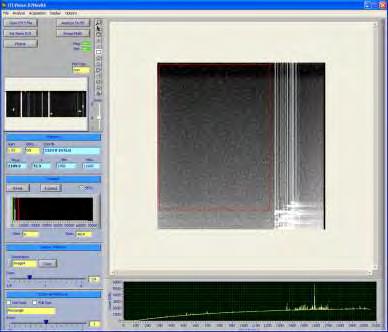
13 CCD Charge Transfer Fe55 image analysis histogram and CTE plots
 line trap global CTE problem")
14 CCD CTE Problems line trap typically due to a short between phases in the image area parallel clock voltage at gates near short are reduced increased applied gate voltage increase normally reduces trap size by increasing effective V gate near trap fat zero or preflash may fill traps very low level exposure or direct input before integration exposure (adds noise) line trap global CTE problem silicon issue?
 g D( e ) 2.")
15 Silicon Dark Current scientific CCD dark signal is typically < C parameter is pa/cm 293K E /2kT D FM is na/cm 300K pix FM A pix pixel area (cm 2 ) g D( e ) 2.5x10 A D T e
16 Back Illuminated CCDs Optical absorption and multiple reflections from frontside structures (polysilicon gates and oxides) reduce efficiency. No blue/uv transmission through polysilicon. Solution is the thin CCD and illuminate detector from backside. Must remove highly doped p + material which CCD is fabricated with to leave only epitaxial material. Typically m thick (100 m for LSST). Interference fringing is worse than for thick devices. If a field-free region remains between the back surface and edge of depletion region, then charge spreading occurs and resolution is degraded. Worse in the blue as photoelectrons are generated near the back surface. Backside surface is a disrupted silicon crystal which has dangling chemical bonds, creating a positively charged interface. This traps electrons at the backside and so a freshly thinned CCD has very poor QE. Adding a negative charge to the back surface is called backside charging and lead to very high QE devices when coupled with AR coatings.

17 ITL Backside CCD Processing Flow The following process steps are performed after device fabrication, which leads to high cost of back illuminated CCDs: Select candidate die via wafer probing Mechanically backside grind Dice wafers Hybridize die to supports Wax protection of edges Selective etch Epitaxial etch Oxidize/passivate Chemisorption Charge Antireflection coat Package Characterize ITL is ~11,000 feet dedicated to scientific and industrial detector processing.

18 UA Foundry Wafer STA design with fabrication though DALSA (now Teledyne DALSA) ITL post-fabrication processing 2 4kx4k CCDs x512 CCDs x800 CCDs 512x1024 FT guiders 128x128 AO devices FBI test devices There are very few fabs in the world making scientific CCDs.


19 STA1600A 10kx10k CCD world s largest integrated circuit 1 die per 150 mm wafer 9 µm pixels 16 high speed outputs probing challenge detector for LBT PEPSI instrument 150 mm silicon wafer, one die per wafer PEPSI dewar with CCD
 W ire b o n d s CCD bumps s ilic o n s u b s tra te p in s m e ta l p a c k a g")
20 STA0500A Back Illuminated CCD STA0500 4kx4k 15 m pixels Typical hybridized large format CCD CCD hybridized to thick silicon substrate for flatness Indium and gold bumps Epoxy underfill Die attached & wire bonded to Kovar, Invar, or ceramic package Detector cost ~ $50,000 back illuminated (< $25k front illuminated) W ire b o n d s CCD bumps s ilic o n s u b s tra te p in s m e ta l p a c k a g e

 STA2200 Orthogonal Transfer")
21 Wafer Probing for Scientific Detectors DC defects get worse when backside thinned Test shorts to 20 M AC image (-60 C) STA2200 Orthogonal Transfer Array -60 C


22 Wafer Dicing Dicing saw Dicing chuck UV tape releaser Wafer taper


23 Detector Hybridization Stud bumper places gold bumps on each detector I/O pad Flip chip bonders are used to align and bond detectors and substrates Infrared or split field aligners Similar to technology used to hybridize IR arrays to readouts


24 Detector Protection for Etching thin region thick region space applications Partial thinning (Antarctic 10k) Wax dispensing


25 Acid Etching acid benches 1:3:8 HF:HNO 3 :CH 3 COOH acid solution used to etch Etch selectivity critical to achieve uniform thickness Typical doping levels p + = cm -3 ; p = cm -3 4 hybridized die Epitaxial etch

 to promote")

26 Backside Coatings Oxidation chamber ITL s Chemisorption Process: Oxidize backside of thinned CCD to reduce interface trap density Apply thin metal film (10A silver) to promote negative backside charge Apply antireflection coating optimized for spectral region of interest AR coating chamber


27 Packaging Packaging is the attachment of the detector to a carrier which can be handled and has electrical I/O connections. Flatness at operating temperature is critical for many scientific applications. Internal structures affect surface profile as does thermal expansion mismatch of materials. 4k CCD in Kovar tub VIRUS 2k CCD for HETDEX WIYN ODI SN8105


28 Packaging - Buttable Imager of WIYN ODI and LSST One Degree Imager top Aluminum Nitride ceramic bottom CE5 frame: Silicon Aluminum alloy for good thermal conductivity and thermal expansion match to silicon/ceramic LSST


29 Wire Bonding Wire bonder Pull testing wire bonds for QA


30 Low Temperature Detector Metrology ITL Cryoscanner Nanovea profilometer pens on large open frame stage with vibration isolation frame holding dewar Metrology performed from +25 C to -150 C LN 2 cooled dewar


31 LSST Prototype Sensor Metrology mm µm mm µm room temp profilometer mm data from -137 C ~4 m peak-valley LN 2 dunker


 500")

32 Curved Detectors Early curved ITL in mid-1990 s but renewed interest from ESO for ELT Reduce optical complexity or increase optical efficiency Its fun when detectors explode! 25 mm radius (1D) 500 mm radius of curvature University of Arizona Imaging Technology Laboratory


33 Detector Characterization
34 Quantum Efficiency The absorptive quantum efficiency QE abs is the fraction of incident photons which is absorbed in the detector, S S e QEabs r r e S a( ) x 0 0 a( ) x (1 ) (1 )(1 ) 0 where x is the thickness of the detector and r is the reflectivity from the incident surface, is the absorption coefficient, S 0 is number of incident photons. Increase QE by 1. reducing reflectivity with antireflection (AR) coatings 2. increasing absorption coefficient (material selection) 3. increasing thickness of absorbing material
35 Backside CCD QE Measured QE 100% 90% 80% 70% 60% 50% 40% 30% 20% 10% 0% Kodak KAF260 Thomson THX7398 Loral LM Orbit 2kx4k Wavelength (um)
36 Backside CCD QE - Ultraviolet Measured QE 100% 90% 80% 200A HfO 2 70% 60% 50% 150A HfO 2 40% 30% 20% 10% 0% Wavelength (nm)
37 QE vs. Temperature
38 Backside QE Enhancement Physics Backside potential well after etching will trap photogenerated electrons and cause an uncharged device to have lower QE than a front illuminated device Caused by positive charge at freshly thinned surface Several techniques are used to produce high QE with backside devices Surface Charging Chemisorption Charging (ITL) Flash gates and UV flooding Internal Charging Implant (doping) and anneal (most common commercially) Delta Doping (Molecular Beam Epitaxy)
39 QE Instability Measured QE 100% 90% 80% 70% 60% 50% 40% 30% 20% 10% 0% +23 C Wavelength (um) 0 C -85 C Incomplete backside charging may cause temperature and time dependent QE variations because the back surface is not pinned with the required negative charge density to drive all photoelectrons to the detector frontside.
40 Ideal QE 10, 20, 50, 100, 300 m Silicon no AR coatings 300 m 10 m fringing reduced for clarity
41 LSST CCD - 93 m thick 100% LSST STA1759A SN % 80% 70% SN7425 Measured QE 60% 50% 40% 30% 20% 10% 0% +25C Comparision to 17 micron thick device with same AR coating University of Arizona Imaging Technology Laboratory M. Lesser 16Jan08 Wavelength (nm)


42 Interference Fringing in Detectors When the absorption length is large compared to the detector thickness, light can reflect multiple times between the front and back surfaces of a detector. This leads to constructive and destructive optical interference within the detector. CCD image with fringing QE plot of back illuminated CCD zoomed fringing

43 Antireflection Coatings An AR coating is a thin film stack applied to the detector surface to decrease reflectivity; typically used on all modern imagers. Coating materials should have proper indices and be non-absorbing in the spectral region of interest. With absorbing substrates which have indices with strong wavelength dependence (like silicon), thin film modeling programs are required to calculate reflectivity. Designer must consider average over incoming beam (f/ ratio) and angle of incidence due to angular dependence.
44 Silicon Reflectivity uncoated Si 1 layer A HfO 2 2 layer 500 A HfO A MgF 2
45 Ideal QE with AR Coatings 50 m silicon uncoated + 1 layer + 2 layer
. Must be transparent. Very high resistance (ultra pure) silicon required to support complete depletion.")
46 Fully Depleted Devices Fully depleted (300 m thick at LBL, 50 m thick commercially). Greatly reduced interference fringing and very high near-ir QE. Backside bias contact required for depletion (~100 V). Must be transparent. Very high resistance (ultra pure) silicon required to support complete depletion. Problems include sensitivity to cosmic rays, higher dark current, backside contact, and charge spreading (resolution loss). 300 m fully depleted CCD QE
47 Field Free Region Charge Spreading The region in a back illuminated CCD between the edge of the depletion region and the back surface is the field-free region. Photogenerated electrons can diffuse in all directions in this region, reducing resolution through charge spreading. Experimentally, C ff L 2 xff (1 ) x ff 1/ 2 5 m FF region => 10 m electron cloud C ff is the lateral diffusion diameter, x ff is the field free thickness, and L is the distance from the backside surface where the photoelectron is generated field free region L x ff e - Higher resistivity material has deeper depletion region (~ 1/ N A ), so x ff is smaller. 50 cm material typical, but ,000 cm possible.


48 Charge Diffusion Full Depletion Fe-55 X-ray events 93 m thick LSST CCD Cooling of custom silicon for high resistivity detectors -50 V backside bias no backside bias
 particles (protons, alphas, electrons, positrons, etc.")
49 Cosmic Rays Silicon is an excellent cosmic ray detector Remove with multiple images Thicker devices are more sensitive Cosmic rays are high energy (MeV) particles (protons, alphas, electrons, positrons, etc.) rate very approximately 100 events cm -2 hr -1
50 Quantum Yield One energetic interacting photon may create multiple electrons-hole pairs through collision (impact ionization) of electrons in conduction band. QY E is the Quantum Yield, E e-h is energy per electron hole pair Ee h Ee h Si, 3.65 ev e Measured QE for E > 3.1 ev ( < ~400 nm) 100% 90% 80% 70% 60% 50% 40% 30% 20% 10% Michael Lesser Univesity of Arizona 200A HfO 2 150A HfO 2 Chemisorption Coated CCDs Room Temperature 0% Wavelength (nm) A 5.9 kev x-ray photon (Fe-55) will create ~1620 electrons per photon in Si 13 micron thickness
51 Detectors with Internal Gain Some non-photoemissive detectors can also have electron gain and may be used for photon counting or very low light level applications. Avalanche photodiodes have gain due to impact ionization when the photoelectron is accelerated in a very high electric field within the silicon. Internal gain CCDs (TI and E2V) utilize an extended serial register and a very high electric field within each pixel. As the CCD shifts charge through this extended register, a small avalanche gain (1.01) is achieved. After ~100 gain stages, an electron packet larger than the read noise is generated and photon counting is possible.
52 Orthogonal Transfer CCDs - OTCCDs Orthogonal transfer devices replace channel stop with a clocked phase, so clocking in both axis directions can be achieved. If centroiding is performed with another detector, the feedback can be used to clock the OTCCD in any direction at high speed to minimize image blurring. OTCCDs are therefore most useful for high resolution imaging, eliminating the need for mechanical motion compensation such as tip/tilt mirrors. Problems include complexity (yield) and charge traps or pockets, which can be enhanced due to repetitive clocking. phases A 5 electron trap will hold 5 electrons even as charge is shifted out of the pixel. Repetitive clocking enhances loss. MIT/LL and John Univ. Hawaii


53 The Orthogonal Transfer Array (OTA) Pan-STARRS and WIYN ODI projects will use OTAs, which monolithic arrays of OTCCDs OTCCD pixel structure Basic OTCCD cell OTA: 8x8 array of OTCCDs Advantages include low susceptibility to internal shorts and restriction of full well blooming to single OTCCD cells. Low shorts->high yield->low cost


54 OTA for WIYN One Degree Imager frontside backside


55 WIYN ODI STA2200A/ITL Backside OTA Fe55 image logic glow grid projection localized defect


56 Focal Plane Assembly Assembly of 14 backside devices onto focal plane Installation of flex cables on backside of focal plane Transport and assembly cart


57 Focal Plane Assembly backside detail of PGA connector & flex cable backside before flex installation custom tool for flex installation

58 Focal Plane Assembly ~25 um peak-valley Final podi focal plane on VIEW Summit 600 CMM

59 CMOS Imagers CMOS imagers utilize a CMOS fabrication process to create an array of photosensors, typically photodiodes. Common devices are monolithic in which readout circuitry is on the same device as the photosensors or hybrid in which the detector is hybridized or flip chip bonded to the readout. Called active pixel sensors (APS) or passive pixel sensors (PPS), depending on pixel structure


60 CCD - CMOS Readout Comparison CMOS Imager amps in every pixel CCD Imager few amps per device From Janesick, OE Magazine, February 2002
61 CMOS Advantages Very low power usage no high voltage required for amps, no large clock voltage swings for charge transfer, little off-chip electronics, 5 or 3.3 V operation. Radiation tolerate CMOS fabrication process. ULSI digital circuitry allows on-chip processing functions, such as ADC, logarithmic gain, multiple sampling, image compression, anti-jitter, color, etc. Random access of pixels charge to voltage conversion at each pixel. No CTE issues as no charge transfer less susceptible to traps. CMOS compatible with 90% of silicon fabrication facilities. Single power source in and digital output is very attractive.
62 CMOS Disadvantages Fill factor is relative size of photosensor to pixel size. Smaller scale design rules for fabrication allow higher fill factor, but is always < 100%. Typically <50%. Noise higher than CCD due to amplifier designs which must drive busses with higher current. Fixed pattern noise high compared to CCDs due to pixel to pixel and column to column gain variations (thousands of amplifiers and capacitors). Typically 0.1 3% variations. Very complex integrated circuits. Circuitry generates heat which increases (local) dark current. Shallow p-n junctions of CMOS processes limit light sensitivity. Commercial push is toward VERY small pixels (1 m) for consumer electronics.

63 4kx4k 15 um pixel CMOS Imager UA Imaging Technology Laboratory Micron Technology, Inc.- 4kx4k 15 m pixel CMOS imager


64 Back Illuminated CMOS Imagers Backside CMOS imager photons Illuminate from backside to enhance QE as with CCDs Avoid stimulating current in active pixel areas which can lead to latchup Backside processing is similar to CCDs with the same silicon properties


65 Back Illuminated CMOS Imagers Each pixel may have different characteristics
66 Teledyne HyViSI TM Devices Hybrid Visible Silicon Imagers Teledyne has developed a hybrid CMOS imager process much like IR detectors. Optimized silicon readout (ROIC) and optimized detector (silicon) allows high efficiency and low noise. Process has been aimed at high speed, but very low noise operation also possible. Formats up to 2kx2k, 18 um pixels <10 electrons read noise 100% fill factor Very cold operation possible as no charge transfer Compatible with IR array controllers


67 Color Sensing CMOS and CCD G R G R G R G R G R B G B G B G B G B G G R G R G R G R G R B G B G B G B G B G Bayer pattern commonly used Color filters placed over each pixel and imaging processing is used to determine an average color for each pixel based on local adjacent intensities. Low sensitivity and spatial resolution compared to monochrome imagers due to filters not used in astronomy
68 References Scientific Charge-Coupled Devices, James Janesick, SPIE Press Monograph Vol. PM83, 2001 Fundamental performance differences between CMOS and CCD imagers: Part II, Janesick, James; Andrews, James; Tower, John; Grygon, Mark; Elliott, Tom; Cheng, John; Lesser, Michael; Pinter, Jeff, Proc. SPIE 6690, p. 3, 2007, also parts I and III Very Large Format Back Illuminated CCDs, Lesser, Michael in Scientific Detectors for Astronomy, Amico, P., Beletic, J. W., and Beletic, J. eds, Kluwer Academic Publishers, 2004, p.137 Secrets of E2V Technologies CCDs, Jorden, P. R.; Pool, P.; Tulloch, S. M., Scientific Detectors for Astronomy, The Beginning of a New Era; eds., Amico, P.; Beletic, J. W.; Beletic, J. E., p ,
VII. IR Arrays & Readout VIII.CCDs & Readout. This lecture course follows the textbook Detection of
 Detection of Light VII. IR Arrays & Readout VIII.CCDs & Readout This lecture course follows the textbook Detection of Light 4-3-2016 by George Rieke, Detection Cambridge of Light Bernhard Brandl University
A Summary of Charge-Coupled Devices for Astronomy
 PUBLICATIONS OF THE ASTRONOMICAL SOCIETY OF THE PACIFIC, 127:1097 1104, 2015 November 2015. The Astronomical Society of the Pacific. All rights reserved. Printed in U.S.A. A Summary of Charge-Coupled Devices
Simulation of High Resistivity (CMOS) Pixels
 Pixels") Simulation of High Resistivity (CMOS) Pixels Stefan Lauxtermann, Kadri Vural Sensor Creations Inc. AIDA-2020 CMOS Simulation Workshop May 13 th 2016 OUTLINE 1. Definition of High Resistivity Pixel Also
Simulation of High Resistivity (CMOS) Pixels Stefan Lauxtermann, Kadri Vural Sensor Creations Inc. AIDA-2020 CMOS Simulation Workshop May 13 th 2016 OUTLINE 1. Definition of High Resistivity Pixel Also
CCD and CMOS Imaging Devices for Large (Ground Based) Telescopes. Veljko Radeka BNL SNIC April 3, 2006
 Telescopes. Veljko Radeka BNL SNIC April 3, 2006") CCD and CMOS Imaging Devices for Large (Ground Based) Telescopes Veljko Radeka BNL SNIC April 3, 2006 1 Large Telescopes Survey telescope Deep probe Primary Mirror dia.=d m, Area= A Large (~8m) Very large
CCD and CMOS Imaging Devices for Large (Ground Based) Telescopes Veljko Radeka BNL SNIC April 3, 2006 1 Large Telescopes Survey telescope Deep probe Primary Mirror dia.=d m, Area= A Large (~8m) Very large
Based on lectures by Bernhard Brandl
 Astronomische Waarneemtechnieken (Astronomical Observing Techniques) Based on lectures by Bernhard Brandl Lecture 10: Detectors 2 1. CCD Operation 2. CCD Data Reduction 3. CMOS devices 4. IR Arrays 5.
Jan Bogaerts imec
 imec 2007 1 Radiometric Performance Enhancement of APS 3 rd Microelectronic Presentation Days, Estec, March 7-8, 2007 Outline Introduction Backside illuminated APS detector Approach CMOS APS (readout)
Fundamentals of CMOS Image Sensors
 CHAPTER 2 Fundamentals of CMOS Image Sensors Mixed-Signal IC Design for Image Sensor 2-1 Outline Photoelectric Effect Photodetectors CMOS Image Sensor(CIS) Array Architecture CIS Peripherals Design Considerations
CCDS. Lesson I. Wednesday, August 29, 12
 CCDS Lesson I CCD OPERATION The predecessor of the CCD was a device called the BUCKET BRIGADE DEVICE developed at the Phillips Research Labs The BBD was an analog delay line, made up of capacitors such
Design and Performance of a Pinned Photodiode CMOS Image Sensor Using Reverse Substrate Bias
 Design and Performance of a Pinned Photodiode CMOS Image Sensor Using Reverse Substrate Bias 13 September 2017 Konstantin Stefanov Contents Background Goals and objectives Overview of the work carried
Two-phase full-frame CCD with double ITO gate structure for increased sensitivity
 Two-phase full-frame CCD with double ITO gate structure for increased sensitivity William Des Jardin, Steve Kosman, Neal Kurfiss, James Johnson, David Losee, Gloria Putnam *, Anthony Tanbakuchi (Eastman
Three Ways to Detect Light. We now establish terminology for photon detectors:
 Three Ways to Detect Light In photon detectors, the light interacts with the detector material to produce free charge carriers photon-by-photon. The resulting miniscule electrical currents are amplified
Detectors that cover a dynamic range of more than 1 million in several dimensions
 Detectors that cover a dynamic range of more than 1 million in several dimensions Detectors for Astronomy Workshop Garching, Germany 10 October 2009 James W. Beletic Teledyne Providing the best images
The Charge-Coupled Device. Many overheads courtesy of Simon Tulloch
 The Charge-Coupled Device Astronomy 1263 Many overheads courtesy of Simon Tulloch smt@ing.iac.es Jan 24, 2013 What does a CCD Look Like? The fine surface electrode structure of a thick CCD is clearly visible
CCD Analogy BUCKETS (PIXELS) HORIZONTAL CONVEYOR BELT (SERIAL REGISTER) VERTICAL CONVEYOR BELTS (CCD COLUMNS) RAIN (PHOTONS)
 HORIZONTAL CONVEYOR BELT (SERIAL REGISTER) VERTICAL CONVEYOR BELTS (CCD COLUMNS) RAIN (PHOTONS)") CCD Analogy RAIN (PHOTONS) VERTICAL CONVEYOR BELTS (CCD COLUMNS) BUCKETS (PIXELS) HORIZONTAL CONVEYOR BELT (SERIAL REGISTER) MEASURING CYLINDER (OUTPUT AMPLIFIER) Exposure finished, buckets now contain
CCD Analogy RAIN (PHOTONS) VERTICAL CONVEYOR BELTS (CCD COLUMNS) BUCKETS (PIXELS) HORIZONTAL CONVEYOR BELT (SERIAL REGISTER) MEASURING CYLINDER (OUTPUT AMPLIFIER) Exposure finished, buckets now contain
Results from the Pan-STARRS Orthogonal Transfer Array (OTA)
") Results from the Pan-STARRS Orthogonal Transfer Array (OTA) John L. Tonry a, Barry E. Burke b, Sidik Isani a, Peter M. Onaka a, Michael J. Cooper b a Institute for Astronomy, University of Hawaii, 2680
Results from the Pan-STARRS Orthogonal Transfer Array (OTA) John L. Tonry a, Barry E. Burke b, Sidik Isani a, Peter M. Onaka a, Michael J. Cooper b a Institute for Astronomy, University of Hawaii, 2680
Detailed Characterisation of a New Large Area CCD Manufactured on High Resistivity Silicon
 Detailed Characterisation of a New Large Area CCD Manufactured on High Resistivity Silicon Mark S. Robbins *, Pritesh Mistry, Paul R. Jorden e2v technologies Ltd, 106 Waterhouse Lane, Chelmsford, Essex
More Imaging Luc De Mey - CEO - CMOSIS SA
 More Imaging Luc De Mey - CEO - CMOSIS SA Annual Review / June 28, 2011 More Imaging CMOSIS: Vision & Mission CMOSIS s Business Concept On-Going R&D: More Imaging CMOSIS s Vision Image capture is a key
Photons and solid state detection
 Photons and solid state detection Photons represent discrete packets ( quanta ) of optical energy Energy is hc/! (h: Planck s constant, c: speed of light,! : wavelength) For solid state detection, photons
Advanced CCD and CMOS Image Sensor Technology at MIT Lincoln Laboratory
 Advanced CCD and CMOS Image Sensor Technology at MIT Lincoln Laboratory Vyshnavi Suntharalingam American Physical Society March Meeting 27 February 2012 CCD Focal Planes on Astronomical Telescopes Lincoln
Three Ways to Detect Light. Following: Lord Rosse image of M33 vs. Hubble image demonstrate how critical detector technology is.
 Three Ways to Detect Light In photon detectors, the light interacts with the detector material to produce free charge carriers photon-by-photon. The resulting miniscule electrical currents are amplified
Detectors for AXIS. Eric D. Miller Catherine Grant (MIT)
") Detectors for AXIS Eric D. Miller Catherine Grant (MIT) Outline detector technology and capabilities CCD (charge coupled device) APS (active pixel sensor) notional AXIS detector background particle environment
Detectors for AXIS Eric D. Miller Catherine Grant (MIT) Outline detector technology and capabilities CCD (charge coupled device) APS (active pixel sensor) notional AXIS detector background particle environment
Detectors for microscopy - CCDs, APDs and PMTs. Antonia Göhler. Nov 2014
 Detectors for microscopy - CCDs, APDs and PMTs Antonia Göhler Nov 2014 Detectors/Sensors in general are devices that detect events or changes in quantities (intensities) and provide a corresponding output,
High Resolution 640 x um Pitch InSb Detector
 High Resolution 640 x 512 15um Pitch InSb Detector Chen-Sheng Huang, Bei-Rong Chang, Chien-Te Ku, Yau-Tang Gau, Ping-Kuo Weng* Materials & Electro-Optics Division National Chung Shang Institute of Science
Silicon sensors for radiant signals. D.Sc. Mikko A. Juntunen
 Silicon sensors for radiant signals D.Sc. Mikko A. Juntunen 2017 01 16 Today s outline Introduction Basic physical principles PN junction revisited Applications Light Ionizing radiation X-Ray sensors in
STA1600LN x Element Image Area CCD Image Sensor
 ST600LN 10560 x 10560 Element Image Area CCD Image Sensor FEATURES 10560 x 10560 Photosite Full Frame CCD Array 9 m x 9 m Pixel 95.04mm x 95.04mm Image Area 100% Fill Factor Readout Noise 2e- at 50kHz
An Introduction to CCDs. The basic principles of CCD Imaging is explained.
 An Introduction to CCDs. The basic principles of CCD Imaging is explained. Morning Brain Teaser What is a CCD? Charge Coupled Devices (CCDs), invented in the 1970s as memory devices. They improved the
Introduction. Chapter 1
 1 Chapter 1 Introduction During the last decade, imaging with semiconductor devices has been continuously replacing conventional photography in many areas. Among all the image sensors, the charge-coupled-device
FUTURE PROSPECTS FOR CMOS ACTIVE PIXEL SENSORS
 FUTURE PROSPECTS FOR CMOS ACTIVE PIXEL SENSORS Dr. Eric R. Fossum Jet Propulsion Laboratory Dr. Philip H-S. Wong IBM Research 1995 IEEE Workshop on CCDs and Advanced Image Sensors April 21, 1995 CMOS APS
Where detectors are used in science & technology
 Lecture 9 Outline Role of detectors Photomultiplier tubes (photoemission) Modulation transfer function Photoconductive detector physics Detector architecture Where detectors are used in science & technology
THE CCD RIDDLE REVISTED: SIGNAL VERSUS TIME LINEAR SIGNAL VERSUS VARIANCE NON-LINEAR
 THE CCD RIDDLE REVISTED: SIGNAL VERSUS TIME LINEAR SIGNAL VERSUS VARIANCE NON-LINEAR Mark Downing 1, Peter Sinclaire 1. 1 ESO, Karl Schwartzschild Strasse-2, 85748 Munich, Germany. ABSTRACT The photon
Tunable wideband infrared detector array for global space awareness
 Tunable wideband infrared detector array for global space awareness Jonathan R. Andrews 1, Sergio R. Restaino 1, Scott W. Teare 2, Sanjay Krishna 3, Mike Lenz 3, J.S. Brown 3, S.J. Lee 3, Christopher C.
CCD1600A Full Frame CCD Image Sensor x Element Image Area
 - 1 - General Description CCD1600A Full Frame CCD Image Sensor 10560 x 10560 Element Image Area General Description The CCD1600 is a 10560 x 10560 image element solid state Charge Coupled Device (CCD)
J. Janesick, S.A. Collins, and E.R. Fossum Imaging Systems Section Jet Propulsion Laboratory Pasadena, CA 91109
 Scientific CCD Technology at JPL J. Janesick, S.A. Collins, and E.R. Fossum maging Systems Section Jet Propulsion Laboratory Pasadena, CA 91109 ntroduction Charge-coupled devices (CCOs) were recognized
Part I. CCD Image Sensors
 Part I CCD Image Sensors 2 Overview of CCD CCD is the abbreviation for charge-coupled device. CCD image sensors are silicon-based integrated circuits (ICs), consisting of a dense matrix of photodiodes
EVALUATION OF RADIATION HARDNESS DESIGN TECHNIQUES TO IMPROVE RADIATION TOLERANCE FOR CMOS IMAGE SENSORS DEDICATED TO SPACE APPLICATIONS
 EVALUATION OF RADIATION HARDNESS DESIGN TECHNIQUES TO IMPROVE RADIATION TOLERANCE FOR CMOS IMAGE SENSORS DEDICATED TO SPACE APPLICATIONS P. MARTIN-GONTHIER, F. CORBIERE, N. HUGER, M. ESTRIBEAU, C. ENGEL,
High-end CMOS Active Pixel Sensor for Hyperspectral Imaging
 R11 High-end CMOS Active Pixel Sensor for Hyperspectral Imaging J. Bogaerts (1), B. Dierickx (1), P. De Moor (2), D. Sabuncuoglu Tezcan (2), K. De Munck (2), C. Van Hoof (2) (1) Cypress FillFactory, Schaliënhoevedreef
Ultra-high resolution 14,400 pixel trilinear color image sensor
 Ultra-high resolution 14,400 pixel trilinear color image sensor Thomas Carducci, Antonio Ciccarelli, Brent Kecskemety Microelectronics Technology Division Eastman Kodak Company, Rochester, New York 14650-2008
An Introduction to Scientific Imaging C h a r g e - C o u p l e d D e v i c e s
 p a g e 2 S C I E N T I F I C I M A G I N G T E C H N O L O G I E S, I N C. Introduction to the CCD F u n d a m e n t a l s The CCD Imaging A r r a y An Introduction to Scientific Imaging C h a r g e -
Charge coupled CMOS and hybrid detector arrays
 Charge coupled CMOS and hybrid detector arrays James Janesick Sarnoff Corporation, 4952 Warner Ave., Suite 300, Huntington Beach, CA. 92649 Headquarters: CN5300, 201 Washington Road Princeton, NJ 08543-5300
TAOS II: Three 88-Megapixel astronomy arrays of large area, backthinned, and low-noise CMOS sensors
 TAOS II: Three 88-Megapixel astronomy arrays of large area, backthinned, and low-noise CMOS sensors CMOS Image Sensors for High Performance Applications TOULOUSE WORKSHOP - 26th & 27th NOVEMBER 2013 Jérôme
Production of HPDs for the LHCb RICH Detectors
 Production of HPDs for the LHCb RICH Detectors LHCb RICH Detectors Hybrid Photon Detector Production Photo Detector Test Facilities Test Results Conclusions IEEE Nuclear Science Symposium Wyndham, 24 th
Properties of a Detector
 Properties of a Detector Quantum Efficiency fraction of photons detected wavelength and spatially dependent Dynamic Range difference between lowest and highest measurable flux Linearity detection rate
TDI Imaging: An Efficient AOI and AXI Tool
 TDI Imaging: An Efficient AOI and AXI Tool Yakov Bulayev Hamamatsu Corporation Bridgewater, New Jersey Abstract As a result of heightened requirements for quality, integrity and reliability of electronic
Lithography. 3 rd. lecture: introduction. Prof. Yosi Shacham-Diamand. Fall 2004
 Lithography 3 rd lecture: introduction Prof. Yosi Shacham-Diamand Fall 2004 1 List of content Fundamental principles Characteristics parameters Exposure systems 2 Fundamental principles Aerial Image Exposure
2K 2K InSb for Astronomy
 2K 2K InSb for Astronomy Alan W. Hoffman *,a, Elizabeth Corrales a, Peter J. Love a, and Joe Rosbeck a, Michael Merrill b, Al Fowler b, and Craig McMurtry c a Raytheon Vision Systems, Goleta, California
Strip Detectors. Principal: Silicon strip detector. Ingrid--MariaGregor,SemiconductorsasParticleDetectors. metallization (Al) p +--strips
 p +--strips") Strip Detectors First detector devices using the lithographic capabilities of microelectronics First Silicon detectors -- > strip detectors Can be found in all high energy physics experiments of the last
Strip Detectors First detector devices using the lithographic capabilities of microelectronics First Silicon detectors -- > strip detectors Can be found in all high energy physics experiments of the last
Abstract. Preface. Acknowledgments
 Contents Abstract Preface Acknowledgments iv v vii 1 Introduction 1 1.1 A Very Brief History of Visible Detectors in Astronomy................ 1 1.2 The CCD: Astronomy s Champion Workhorse......................
Dynamic Range. Can I look at bright and faint things at the same time?
 Detector Basics The purpose of any detector is to record the light collected by the telescope. All detectors transform the incident radiation into a some other form to create a permanent record, such as
Charged Coupled Device (CCD) S.Vidhya
 S.Vidhya") Charged Coupled Device (CCD) S.Vidhya 02.04.2016 Sensor Physical phenomenon Sensor Measurement Output A sensor is a device that measures a physical quantity and converts it into a signal which can be read
Charged Coupled Device (CCD) S.Vidhya 02.04.2016 Sensor Physical phenomenon Sensor Measurement Output A sensor is a device that measures a physical quantity and converts it into a signal which can be read
Gas scintillation Glass GEM detector for high-resolution X-ray imaging and CT
 Gas scintillation Glass GEM detector for high-resolution X-ray imaging and CT Takeshi Fujiwara 1, Yuki Mitsuya 2, Hiroyuki Takahashi 2, and Hiroyuki Toyokawa 2 1 National Institute of Advanced Industrial
TELEDYNE S HIGH PERFORMANCE INFRARED DETECTORS FOR SPACE MISSIONS. Paul Jerram and James Beletic ICSO October 2018
 TELEDYNE S HIGH PERFORMANCE INFRARED DETECTORS FOR SPACE MISSIONS Paul Jerram and James Beletic ICSO October 2018 Teledyne High Performance Image Sensors Teledyne DALSA Waterloo, Ontario (Design, I&T)
Characterisation of a Novel Reverse-Biased PPD CMOS Image Sensor
 Characterisation of a Novel Reverse-Biased PPD CMOS Image Sensor Konstantin D. Stefanov, Andrew S. Clarke, James Ivory and Andrew D. Holland Centre for Electronic Imaging, The Open University, Walton Hall,
Optical/IR Observational Astronomy Detectors II. David Buckley, SAAO
 David Buckley, SAAO 1 The Next Revolution: Charge Couple Device Detectors (CCDs) 2 Optical/IR Observational Astronomy CCDs Integrated semi-conductor detector From photon detection (pair production) to
Image Formation and Capture. Acknowledgment: some figures by B. Curless, E. Hecht, W.J. Smith, B.K.P. Horn, and A. Theuwissen
 Image Formation and Capture Acknowledgment: some figures by B. Curless, E. Hecht, W.J. Smith, B.K.P. Horn, and A. Theuwissen Image Formation and Capture Real world Optics Sensor Devices Sources of Error
Laboratory, University of Arizona, Tucson, AZ 85721; c ImagerLabs, 1995 S. Myrtle Ave., Monrovia CA INTRODUCTION ABSTRACT
 A CMOS Visible Image Sensor with Non-Destructive Readout Capability Gary R. Sims* a, Gene Atlas c, Eric Christensen b, Roger W. Cover a, Stephen Larson b, Hans J. Meyer a, William V. Schempp a a Spectral
Semiconductor Detector Systems
 Semiconductor Detector Systems Helmuth Spieler Physics Division, Lawrence Berkeley National Laboratory OXFORD UNIVERSITY PRESS ix CONTENTS 1 Detector systems overview 1 1.1 Sensor 2 1.2 Preamplifier 3
Charged-Coupled Devices
 Charged-Coupled Devices Charged-Coupled Devices Useful texts: Handbook of CCD Astronomy Steve Howell- Chapters 2, 3, 4.4 Measuring the Universe George Rieke - 3.1-3.3, 3.6 CCDs CCDs were invented in 1969
Minimizes reflection losses from UV-IR; Optional AR coatings & wedge windows are available.
 Now Powered by LightField PyLoN:2K 2048 x 512 The PyLoN :2K is a controllerless, cryogenically-cooled CCD camera designed for quantitative scientific spectroscopy applications demanding the highest possible
Fully depleted, thick, monolithic CMOS pixels with high quantum efficiency
 Fully depleted, thick, monolithic CMOS pixels with high quantum efficiency Andrew Clarke a*, Konstantin Stefanov a, Nicholas Johnston a and Andrew Holland a a Centre for Electronic Imaging, The Open University,
Selecting an image sensor for the EJSM VIS/NIR camera systems
 Selecting an image sensor for the EJSM VIS/NIR camera systems presented by Harald Michaelis (DLR-PF) Folie 1 EJSM- Jan. 18th 2010; ESTEC What for a detector/sensor we shall chose for EJSM? Vortragstitel
Hybridization process for back-illuminated silicon Geigermode avalanche photodiode arrays
 Hybridization process for back-illuminated silicon Geigermode avalanche photodiode arrays The MIT Faculty has made this article openly available. Please share how this access benefits you. Your story matters.
Soft X-Ray Silicon Photodiodes with 100% Quantum Efficiency
 PFC/JA-94-4 Soft X-Ray Silicon Photodiodes with 1% Quantum Efficiency K. W. Wenzel, C. K. Li, D. A. Pappas, Raj Kordel MIT Plasma Fusion Center Cambridge, Massachusetts 2139 USA March 1994 t Permanent
SILICON NANOWIRE HYBRID PHOTOVOLTAICS
 SILICON NANOWIRE HYBRID PHOTOVOLTAICS Erik C. Garnett, Craig Peters, Mark Brongersma, Yi Cui and Mike McGehee Stanford Univeristy, Department of Materials Science, Stanford, CA, USA ABSTRACT Silicon nanowire
Application of CMOS sensors in radiation detection
 Application of CMOS sensors in radiation detection S. Ashrafi Physics Faculty University of Tabriz 1 CMOS is a technology for making low power integrated circuits. CMOS Complementary Metal Oxide Semiconductor
Quality Assurance for the ATLAS Pixel Sensor
 Quality Assurance for the ATLAS Pixel Sensor 1st Workshop on Quality Assurance Issues in Silicon Detectors J. M. Klaiber-Lodewigs (Univ. Dortmund) for the ATLAS pixel collaboration Contents: - role of
ABSTRACT 1. INTRODUCTION
 Teledyne s High Performance Infrared Detectors for Space Missions Paul Jerram a and James Beletic b a Teledyne e2v Space Imaging, Chelmsford, UK, CM7 4BS b Teledyne Imaging Sensors, Camarillo, California,
Light gathering Power: Magnification with eyepiece:
 Telescopes Light gathering Power: The amount of light that can be gathered by a telescope in a given amount of time: t 1 /t 2 = (D 2 /D 1 ) 2 The larger the diameter the smaller the amount of time. If
IT FR R TDI CCD Image Sensor
 4k x 4k CCD sensor 4150 User manual v1.0 dtd. August 31, 2015 IT FR 08192 00 R TDI CCD Image Sensor Description: With the IT FR 08192 00 R sensor ANDANTA GmbH builds on and expands its line of proprietary
Image sensor combining the best of different worlds
 Image sensors and vision systems Image sensor combining the best of different worlds First multispectral time-delay-and-integration (TDI) image sensor based on CCD-in-CMOS technology. Introduction Jonathan
Overview. Charge-coupled Devices. MOS capacitor. Charge-coupled devices. Charge-coupled devices:
 Overview Charge-coupled Devices Charge-coupled devices: MOS capacitors Charge transfer Architectures Color Limitations 1 2 Charge-coupled devices MOS capacitor The most popular image recording technology
STA3600A 2064 x 2064 Element Image Area CCD Image Sensor
 ST600A 2064 x 2064 Element Image Area CCD Image Sensor FEATURES 2064 x 2064 CCD Image Array 15 m x 15 m Pixel 30.96 mm x 30.96 mm Image Area Near 100% Fill Factor Readout Noise Less Than 3 Electrons at
CCD Characteristics Lab
 CCD Characteristics Lab Observational Astronomy 6/6/07 1 Introduction In this laboratory exercise, you will be using the Hirsch Observatory s CCD camera, a Santa Barbara Instruments Group (SBIG) ST-8E.
EE119 Introduction to Optical Engineering Spring 2003 Final Exam. Name:
 EE119 Introduction to Optical Engineering Spring 2003 Final Exam Name: SID: CLOSED BOOK. THREE 8 1/2 X 11 SHEETS OF NOTES, AND SCIENTIFIC POCKET CALCULATOR PERMITTED. TIME ALLOTTED: 180 MINUTES Fundamental
Advances in X-Ray Scintillator Technology Roger D. Durst Bruker AXS Inc.
 Advances in X-Ray Scintillator Technology Roger D. Durst Inc. Acknowledgements T. Thorson, Y. Diawara, E. Westbrook, MBC J. Morse, ESRF C. Summers, Georgia Tech/PTCE B. Wagner, Georgia Tech/PTCE V. Valdna,
Minimizes reflection losses from UV to IR; No optical losses due to multiple optical surfaces; Optional AR coating and wedge windows available.
 SOPHIA: 2048B The SOPHIA : 2048B camera from Princeton Instruments (PI) is fully integrated, ultra-low noise 2048 x 2048, 15 µm pixel CCD camera designed expressly for the most demanding quantitative scientific
Index. Cambridge University Press Silicon Photonics Design Lukas Chrostowski and Michael Hochberg. Index.
 absorption, 69 active tuning, 234 alignment, 394 396 apodization, 164 applications, 7 automated optical probe station, 389 397 avalanche detector, 268 back reflection, 164 band structures, 30 bandwidth
New fabrication and packaging technologies for CMOS pixel sensors: closing gap between hybrid and monolithic
 New fabrication and packaging technologies for CMOS pixel sensors: closing gap between hybrid and monolithic Outline Short history of MAPS development at IPHC Results from TowerJazz CIS test sensor Ultra-thin
Visible Light Photon R&D in the US. A. Bross KEK ISS Meeting January 25, 2006
 Visible Light Photon R&D in the US A. Bross KEK ISS Meeting January 25, 2006 Some History First VLPC History In 1987, a paper was published by Rockwell detailing the performance of Solid State PhotoMultipliers
200mm and 300mm Test Patterned Wafers for Bonding Process Applications SKW ASSOCIATES, INC.
 C M P C h a r a c t e r I z a t I o n S o l u t I o n s 200mm and 300mm Test Patterned Wafers for Bonding Process Applications SKW ASSOCIATES, INC. 2920 Scott Blvd., Santa Clara, CA 95054 Tel: 408-919-0094,
Characterisation of a CMOS Charge Transfer Device for TDI Imaging
 Preprint typeset in JINST style - HYPER VERSION Characterisation of a CMOS Charge Transfer Device for TDI Imaging J. Rushton a, A. Holland a, K. Stefanov a and F. Mayer b a Centre for Electronic Imaging,
Development of Double-sided Silcon microstrip Detector. D.H. Kah*, H. Park, H.J. Kim (BAERI JikLee (SNU) E. Won (Korea U)
 E. Won (Korea U)") Development of Double-sided Silcon microstrip Detector D.H. Kah*, H. Park, H.J. Kim (BAERI JikLee (SNU) E. Won (Korea U), KNU) 2005 APPI dhkah@belle.knu.ac.kr 1 1. Motivation 2. Introduction Contents 1.
Development of Double-sided Silcon microstrip Detector D.H. Kah*, H. Park, H.J. Kim (BAERI JikLee (SNU) E. Won (Korea U), KNU) 2005 APPI dhkah@belle.knu.ac.kr 1 1. Motivation 2. Introduction Contents 1.
Charge-Coupled Device (CCD) Detectors pixel silicon chip electronics cryogenics
 Detectors pixel silicon chip electronics cryogenics") Charge-Coupled Device (CCD) Detectors As revolutionary in astronomy as the invention of the telescope and photography semiconductor detectors a collection of miniature photodiodes, each called a picture
Charge-Coupled Device (CCD) Detectors As revolutionary in astronomy as the invention of the telescope and photography semiconductor detectors a collection of miniature photodiodes, each called a picture
Fabrication of High-Speed Resonant Cavity Enhanced Schottky Photodiodes
 Fabrication of High-Speed Resonant Cavity Enhanced Schottky Photodiodes Abstract We report the fabrication and testing of a GaAs-based high-speed resonant cavity enhanced (RCE) Schottky photodiode. The
CCDs for Earth Observation James Endicott 1 st September th UK China Workshop on Space Science and Technology, Milton Keynes, UK
 CCDs for Earth Observation James Endicott 1 st September 2011 7 th UK China Workshop on Space Science and Technology, Milton Keynes, UK Introduction What is this talk all about? e2v sensors in spectrometers
Characteristic of e2v CMOS Sensors for Astronomical Applications
 Characteristic of e2v CMOS Sensors for Astronomical Applications Shiang-Yu Wang* a, Hung-Hsu Ling a, Yen-Sang Hu a, John C. Geary b, Stephen M. Amato b, Jerome Pratlong c, Andrew Pike c, Paul Jorden c
Application Bulletin 240
 Application Bulletin 240 Design Consideration CUSTOM CAPABILITIES Standard PC board fabrication flexibility allows for various component orientations, mounting features, and interconnect schemes. The starting
Section 2: Lithography. Jaeger Chapter 2 Litho Reader. The lithographic process
 Section 2: Lithography Jaeger Chapter 2 Litho Reader The lithographic process Photolithographic Process (a) (b) (c) (d) (e) (f) (g) Substrate covered with silicon dioxide barrier layer Positive photoresist
The HGTD: A SOI Power Diode for Timing Detection Applications
 The HGTD: A SOI Power Diode for Timing Detection Applications Work done in the framework of RD50 Collaboration (CERN) M. Carulla, D. Flores, S. Hidalgo, D. Quirion, G. Pellegrini IMB-CNM (CSIC), Spain
Section 2: Lithography. Jaeger Chapter 2 Litho Reader. EE143 Ali Javey Slide 5-1
 Section 2: Lithography Jaeger Chapter 2 Litho Reader EE143 Ali Javey Slide 5-1 The lithographic process EE143 Ali Javey Slide 5-2 Photolithographic Process (a) (b) (c) (d) (e) (f) (g) Substrate covered
PRELIMINARY. CCD 3041 Back-Illuminated 2K x 2K Full Frame CCD Image Sensor FEATURES
 CCD 3041 Back-Illuminated 2K x 2K Full Frame CCD Image Sensor FEATURES 2048 x 2048 Full Frame CCD 15 µm x 15 µm Pixel 30.72 mm x 30.72 mm Image Area 100% Fill Factor Back Illuminated Multi-Pinned Phase
Engineering Medical Optics BME136/251 Winter 2018
 Engineering Medical Optics BME136/251 Winter 2018 Monday/Wednesday 2:00-3:20 p.m. Beckman Laser Institute Library, MSTB 214 (lab) *1/17 UPDATE Wednesday, 1/17 Optics and Photonic Devices III: homework
Nanotechnology, the infrastructure, and IBM s research projects
 Nanotechnology, the infrastructure, and IBM s research projects Dr. Paul Seidler Coordinator Nanotechnology Center, IBM Research - Zurich Nanotechnology is the understanding and control of matter at dimensions
Chapter 3: Sensing the light: Detectors for the Optical and Infrared
 Chapter 3: Sensing the light: Detectors for the Optical and Infrared 3.1 Basic Properties of Photo-detectors Modern photon detectors operate by placing a bias voltage across a semiconductor crystal, illuminating
CCD Procurement Specification EUV Imaging Spectrometer
 Solar-B EIS * CCD Procurement Specification EUV Imaging Spectrometer Title CCD Procurement specification Doc ID MSSL/SLB-EIS/SP/02 ver 2.0 Author Chris McFee Date 25 March 2001 Ver 2.0 Page 2 of 10 Contents
EE 392B: Course Introduction
 EE 392B Course Introduction About EE392B Goals Topics Schedule Prerequisites Course Overview Digital Imaging System Image Sensor Architectures Nonidealities and Performance Measures Color Imaging Recent
Micro-sensors - what happens when you make "classical" devices "small": MEMS devices and integrated bolometric IR detectors
 Micro-sensors - what happens when you make "classical" devices "small": MEMS devices and integrated bolometric IR detectors Dean P. Neikirk 1 MURI bio-ir sensors kick-off 6/16/98 Where are the targets
DV420 SPECTROSCOPY. issue 2 rev 1 page 1 of 5m. associated with LN2
 SPECTROSCOPY Andor s DV420 CCD cameras offer the best price/performance for a wide range of spectroscopy applications. The 1024 x 256 array with 26µm 2 pixels offers the best dynamic range versus resolution.
Adaptive Optics for LIGO
 Adaptive Optics for LIGO Justin Mansell Ginzton Laboratory LIGO-G990022-39-M Motivation Wavefront Sensor Outline Characterization Enhancements Modeling Projections Adaptive Optics Results Effects of Thermal
Factors Affecting Pixel Scaling Limits for cellphone imaging systems
 Factors Affecting Pixel Scaling Limits for cellphone imaging systems October 28, 2010 Richard Crisp rcrisp@narrowbandimaging.com Agenda Pixel Scaling Limits Optical Considerations Image Sensor Considerations
Image Formation and Capture
 Figure credits: B. Curless, E. Hecht, W.J. Smith, B.K.P. Horn, A. Theuwissen, and J. Malik Image Formation and Capture COS 429: Computer Vision Image Formation and Capture Real world Optics Sensor Devices