ARP AVATAR PATCH PANEL INSTALLATION MANUAL
|
|
|
- Albert Howard
- 5 years ago
- Views:
Transcription

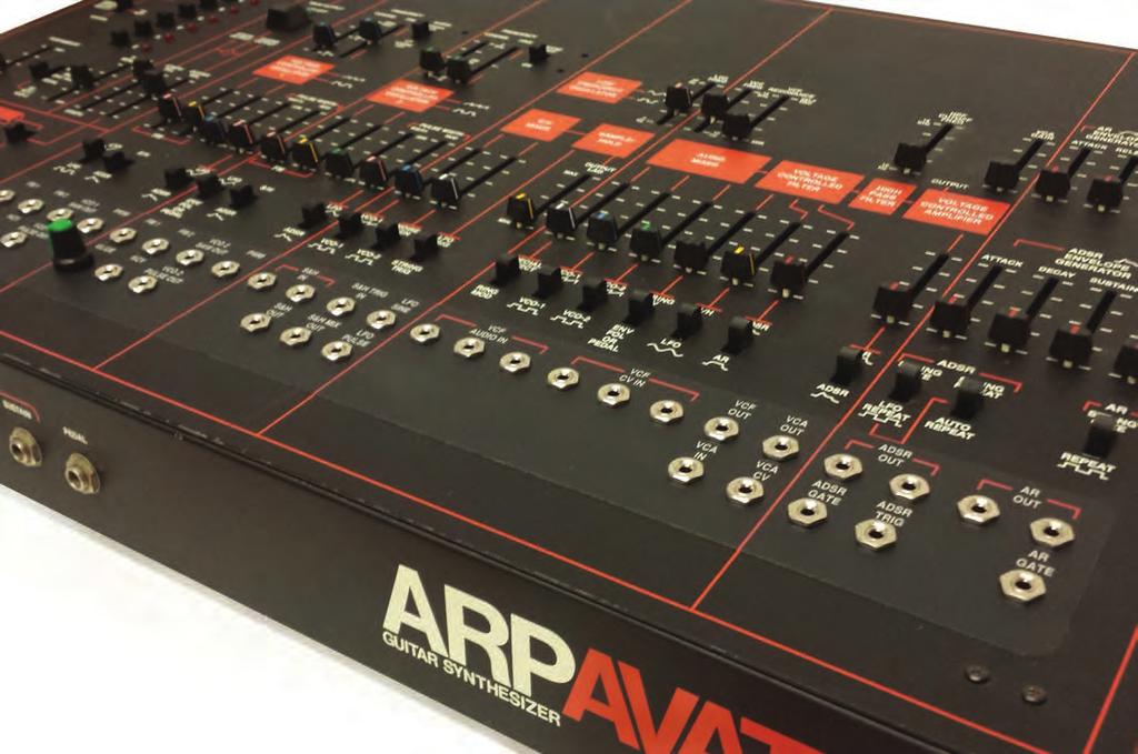
1 ARP AVATAR PATCH PANEL INSTALLATION MANUAL
2 Introduction Thank you for purchasing an Avatar Patch Panel Kit! These instructions are intended to guide you through installing and using this kit. Before we get started, let s go over a few guidelines: Never open the Avatar or perform any service on it when the unit is plugged in to AC power. Take your time when drilling in to the front panel and when making cuts to traces on the circuit boards. Careless work can damage your instrument and diminish its resale value. This work should be performed by persons experienced with electronics and mechanical construction. This modification is considered advanced and should not be undertaken by the novice. Please consider hiring a professional technician or engineer to do this work if you are not comfortable. This kit will take 8-10 hours for an experienced technician to install Kit Contents Polycarbonate Graphic Panel (2) Potentiometers Heat Shrink Tubing (2) 50 pin IDC cables 1 PCB (36) 1/8 Switching Jacks (36) 3/8 Mounting Nuts (1) 1M Resistor (2) 50-Pin IDC Connectors
3 Tools Required For Installation Electric Drill or Drill Press 6.5mm Drill Bit Center Punch Wire cutters Wire strippers Solder Soldering Iron Dremel or Exact-O Knife Phillips Head Screwdriver Heat Gun or Hair Dryer Positioning, Marking, and Drilling The vinyl adhesive panel overlay is used as a template for marking and drilling the ARP Avatar front panel. Line up the graphics horizontally and adjust vertically so the top edge of the vinyl overlay just meets the orange front panel graphic under the LFO Repeat switch. The bottom edge of the vinyl overlay should be approximately 33mm from the bottom edge of the Avatar front panel. Secure in position with removable tape taking care not to obstruct the holes in the overlay. Accurately mark the center of the openings, remove the overlay, and drill the VCO1 glide and VCO2 glide locations to all other holes to 6.5mm. Deburr the holes on both sides of the panel. If drilling the panel by hand, always remove the front panel and PCBs, and use a sharp center punch to prep each drilling location to minimize the drill bit wandering. If using a drill press, remove the circuit boards from the front panel and remove the panel from the case. Wooden spacer blocks will be needed under the panel to level it while drilling.


4 Figure 1A - Alignment of Overlay Figure 1B - Alignment of Overlay


5 Assembled PCB (Top View) Assembled PCB (Bottom View)


6 IDC Headers Mounted to PCB Proper Orientation of Ribbon Cables
7 Panel Mounting and PCB Mounting Before affixing the vinyl overlay to the Avatar panel, dry fit and verify the alignment of the overlay, panel holes, and patch board hardware, securing the jack hardware only loosely in place. Inaccurately drilled panel holes may result in a slight buckling or misalignment of the overlay which can be remedied by slightly enlarging the misaligned holes. The vinyl overlay has a strong adhesive, so use care in affixing it to the panel. Attach the 36 1/8 switching jacks and pots to the top of the PCB. Attach IDC connectors to the bottom of the PCB. Pay close attention to the keying of the IDC connectors as well. Pin 1 is always marked on the IDC header with either a 1 or a triangle pointing to pin 1. Make sure you know which pin is pin 1 (brown wire) before you start wiring. IDC Header A is on the left side of the PCB (contains VCOs, S&H, etc) and Header B is on the right side (VCF, VCA, Envelopes.) Electrical Mods and Connections Several conductive traces must be cut (electrically open) on the Avatar circuit boards. This is best done with a rotary tool such as a Dremel but can also be accomplished with a sharp utility or hobby knife. The following pages have diagrams of the circuit boards to be modified. There are certain conventions that must be followed when using the diagrams. A cut to the PCB is indicated with a yellow line. Each cut will require that a wire be tack soldered on to each side of the cut. A trace that does not need to be cut, but still has a wire attached to it will be indicated with a yellow dot. A wire will be needed on the oscillator board, and it is indicated by a purple line. The diagrams have a letter and a number indicating which wires should be soldered to each point. The letter A indicates that a wire is on the left front panel PCB cable. The letter B indicates that the wire is in the right front panel PCB cable. There are 50 wires on each cable. The brown wire indicates pin 1. For example, A12 would mean wire 12 on the left front panel PCB cable. Trim the wires in the cables to the lengths needed to reach the point on the PCB where they will be soldered.
8 A29 A1 A2 A3 A4 A11 A12 A13 A14 A15 A16 Figure 2. Board B Top Left
9 A26 A28 A31 A32 A15 A16 A23 A24 A25 A27 A33 A34 Figure 3. Board B Top Center

10 A30 Figure 4. Board B Top Right
11 A5 A6 Wire Figure 5. Board B Bottom Left A18 A17 Figure 6. Board B Bottom Center

12 A35, A36, A39 A40, A43, A44 A47, A48 A19, A20 A21, A22 A7, A8, A9, A10 Figure 7. Board B Bottom Right

13 B22 B21 B2 B1 B4 B3 B6 B8 B7 B10 B9 B12 B11 B5 A49 A41 A37 A50 A42 A38 Do not cut. This is from another modification. Figure 8. Board C Top Left

14 Figure 9. Board C Top Center

15 B26 B25 Figure 10. Board C Top Right


16 B31 B18 B17 Figure 11 Board C Bottom Left
17 vcf Connections When connecting the VCF portion of the patch panel to the Avatar PCB, mote that a resistor must be removed, and two wires of the IDE cable must be connected and soldered together. Figure 11 has a yellow dotted box to indicate that the 1M resistor in the pcb above must be removed. This can be done easily if you have a vacuum desoldering tool. We recommend removing the solder from the PCB side and then using a wire to gently poke the loose resistor from the mounting holes. Be sure to recover the old resistor so it isn t left in the chassis. If you have removed board C, you can simply clip the resistor out. Once the resistor is removed, solder the 1M resistor to the PCB as shown in figure 11. Attach wire B31 to the other end of the resistor. Be sure to use some of the heat shrink tubing included in the kit to prevent exposed metal and shorts. Now, connect B36 to B32. This can be done using the wires or simply by connecting those pins on the IDC header. Reassembly and Testing Be sure to test all of the functions on the patch panel and check your work before reassembling the avatar. Take care not to leave any metal shavings or loose debris in the case before closing. You re finished! Enjoy your newly expanded Avatar.
18
Instructions for Lighting an S Scale Caboose
 Instructions for Lighting an S Scale Caboose The S Scale Caboose lighting kit is adaptable for most caboose models of rolling stock including American Flyer (TM) and contains the same components as found
ABC V1.0 ASSEMBLY IMPORTANT!
 ABC V1.0 ASSEMBLY Before starting this kit, prepare the following tools: Soldering iron (15-20W will do), flush cutters, no.2 hex screwdriver or allen key and phillips screwdriver. Also briefly go through
Team Xecuter Joycon Mod By: XxWiReDxX
 Team Xecuter Joycon Mod By: XxWiReDxX Works With Every Switch SX OS Works with every Nintendo Switch and every firmware version! Play Every Game With SX OS you can play all your favorite games straight
Bachmann GP7 Tsunami Digital Sound Decoder Installation Notes
 Bachmann GP7 Tsunami Digital Sound Decoder Installation Notes Overview This application note describes how to install a TSU-AT1000 digital sound decoder into a Bachmann HO GP7. Skill Level 3: One to three
Telecaster Wiring Kits Please Read All Instructions Before Beginning. Tools you will need: Soldering tips: Removing Current Wiring: Step 1. Step 2.
 Telecaster Wiring Kits Please Read All Instructions Before Beginning. Tools you will need: Soldering Iron (35 watt preferably) Solder Wet Sponge Wire Clippers Wire Strippers 3/8 Drill Bit 5/32 Drill Bit
LITTLE NERD v1.1 Assembly Guide
 last update: 9. 3. 2016 LITTLE NERD v1.1 Assembly Guide bastl instruments.com INTRODUCTION This guide is for building Little Nerd module from Bastl Instruments. It is good to have basic soldering skills
Section 5 BATTERY REPLACEMENT
 u Section 5 BATTERY REPLACEMENT j i 5.1 General The internal battery is used for preserving the clock and programming memory in the models 5000 and 7000. I i The procedure for each is given separately.
BrewsBySmith.com STC DIY Kit
 BrewsBySmith.com STC-1000 + DIY Kit Contact Information: Greg Smith www.brewsbysmith.com greg@boostbysmith.com I. Hardware Included: STC-1000 flashed with latest software (v1.06 currently) (if purchased)
VC Divider Assembly manual
 1 VC Divider Assembly manual Thank you for your purchase of the SSSR Labs VC Divider DIY Kit! This manual will help you assemble the VC Divider quickly and easily. Follow the instructions! As you may know,
LP-200 Dummy Load / Wattmeter
 LP-200 Dummy Load / Wattmeter Enclosure Retrofit Assembly Instructions March 2009 TelePost Incorporated LP-200 is a trademark of TelePost Inc. Material in this document copyrighted 2009 TelePost Inc. 1
Bowser Baldwin AS-16 Tsunami Digital Sound Decoder Installation Notes
 Bowser Baldwin AS-16 Tsunami Digital Sound Decoder Installation Notes Overview This application note describes how to install a TSU-BW1000 digital sound decoder into a Bowser HO Baldwin AS-16. Skill Level
Explorer Wiring Kit (assembled)
") Explorer Wiring Kit (assembled) For Vintage, Firestorm & Standard Series Please Read All Instructions Before Beginning. Tools you will need: Soldering Iron (35 watt preferably) Solder Wet Sponge Wire Clippers
Explorer Wiring Kit (assembled) For Vintage, Firestorm & Standard Series Please Read All Instructions Before Beginning. Tools you will need: Soldering Iron (35 watt preferably) Solder Wet Sponge Wire Clippers
Intellivision A/V Mod Installation Guide
 Intellivision A/V Mod Installation Guide This document will guide you through installing your Intellivision A/V Mod Kit to your Intellivision I, II, and III game consoles. Installation is basically the
Pacific Antenna RF Probe assembly
 Pacific Antenna RF Probe assembly Parts In the Kit: 1 1/2 x 3 Blue PEX tube 2 5/8 O.D. vinyl caps 2 3/32 dia x 2 brass tube sections 2 Pogo spring contacts 1 4-40 x 7/16 pan head screw 1 4-40 x 1/4 pan
Written By: Darren Chan
 Sega Dreamcast Controller Port Replacement Written By: Darren Chan ifixit CC BY-NC-SA www.ifixit.com Page 1 of 10 INTRODUCTION Replacing the F1 fuse on the controller board of the Sega Dreamcast. Soldering
Installation tutorial for Console Customs Xbox Mode Dual Button (RFX-5B) Rapid fire Microchip for all Wired and Wireless controllers
 Rapid fire Microchip for all Wired and Wireless controllers") Installation tutorial for Console Customs Xbox 360 5-Mode Dual Button (RFX-5B) Rapid fire Microchip for all Wired and Wireless controllers This tutorial is designed to aid you in installation of a console
Installation tutorial for Console Customs Xbox 360 5-Mode Dual Button (RFX-5B) Rapid fire Microchip for all Wired and Wireless controllers This tutorial is designed to aid you in installation of a console
TOYOTA CAMRY LIP SPOILER Preparation
 Preparation Part Number: PT29A-03070-XX Kit Contents 1 1 Lip Spoiler 2 1 Hardware Bag Hardware Bag Contents 1 2 M6 Nuts 2 2 M6 Bolts Additional Items Required For Installation 1 1 Installation Kit, P/N
The ability to make basic voltage and resistance measurements using a digital multimeter
 Congratulations on your purchase of a new OneShot chassis! The PC01 OneShot combines a rugged enclosure, power supply, and discrete instrument DI in a compact 1/4U package. A few minutes of assembly are
2 Recommended Tools / Supplies
 Bias Scout TM Kit Assembly Manual Version 3.1 25 March 2015 1 Inventory of Parts 1 ea octal socket 1 ea octal base, brown (1 3/16" dia x 7/8" high) 1 ea 1.0 / 1W metal oxide, flame proof resistor 1 ea
Dual CV Source + Attenuator/Mixer
 Dual CV Source + Attenuator/Mixer Model 9744 Assembly and Using Manual This second-generation 9700-series processing element for modular sound synthesizers is designed to provide great sound and excellent
Standard Kit #1 (3-way switch)
") Standard Kit #1 (3-way switch) Please Read All Instructions Before Beginning. Tools you will need: Soldering Iron (35 watt preferably) Solder Wet Sponge Wire Clippers 3/8 Drill Bit 1/4 Drill Bit Variable
Standard Kit #1 (3-way switch) Please Read All Instructions Before Beginning. Tools you will need: Soldering Iron (35 watt preferably) Solder Wet Sponge Wire Clippers 3/8 Drill Bit 1/4 Drill Bit Variable
Pingable Envelope Generator
 Pingable Envelope Generator Kit Builder's Guide for PCB v1.0.3 4mspedals.com PEG This guide is for building a Pingable Envelope Generator (PEG), which is an intermediate-level kit. You should be confident
Application Note. Atlas B23-7 Tsunami Digital Sound Decoder Installation Notes
 Application Note Atlas B23-7 Tsunami Digital Sound Decoder Installation Notes Overview This application note describes how to install a TSU-1000 digital sound decoder into an Atlas B23-7. Skill Level 2:
Never power this piano with anything other than a standard 9V battery!
 Welcome to the exciting world of Digital Electronics! Who is this kit intended for? This kit is intended for anyone from ages 13 and above and assumes no previous knowledge in the field of hobby electronics.
Application Note. Bowser-Stewart VO-1000 Tsunami Digital Sound Decoder Installation Notes
 Application Note Overview This application note describes how to install a TSU-1000 Digital Sound Decoder into the Bowser-Stewart VO-1000 Locomotive. Skill Level 4: The entire installation can be completed
Raygun. Vector Weapon. projects. Raygun vector weapon. Build a mini analog sound-effects circuit. By Symetricolour. Time: 2 4 hours CosT: $15 $20
 projects Raygun vector weapon Raygun Vector Weapon By Symetricolour Time: 2 4 hours CosT: $5 $20 Build a mini analog sound-effects circuit. Gregory Hayes 02 Materials» raygun Vector Weapon Kit item #MSVWP
Micro Channel. Shorten the Fixture (optional) Installation Instructions for 700UMCD_ UNILUME. This product is suitable for damp locations.
 Installation Instructions for 700UMCD_ UNILUME. This product is suitable for damp locations.") Installation Instructions for Micro Channel 700UMCD_ 90MICRO. UNILUME GENERAL PRODUCT I NFORMATION: This product is suitable for damp locations. This product can be dimmed with a low-voltage electronic
Installation Instructions for Micro Channel 700UMCD_ 90MICRO. UNILUME GENERAL PRODUCT I NFORMATION: This product is suitable for damp locations. This product can be dimmed with a low-voltage electronic
No crimping is required just solder the the wire to the crimp piece and use some heat shrink tubing to cover the end of the crimp.
 In this section we will be wiring up the IEC socket (AC plug) with the rocker switch and the Mains transformer primaries. Follow these instructions if you live in an area with 100, 110, 220 or 230 Volts!"
PCB DESIGN AND MOUNTING
 PULL-THRU USER S MANUAL: SECTION 1 PCB DESIGN AND MOUNTING TOOLS REQUIRED Phillips Head Screwdriver ASSEMBLY INSTRUCTIONS 1. Lay out, design, and manufacture PCB according to Figure A. The height of any
Word Clock. Enclosure Construction Notes
 Word Clock Enclosure Construction Notes DougsWordClocks.com Pty Ltd April 2013 V2.0 Licence The Word Clock Design, PCB layout, Manual, and Firmware is Copyright 2009-2013, by DougsWordClocks.com Pty Ltd.
Modifying the Hextronik HX5010 Servo Motors for Babuinobot 1.0
 Modifying the Hextronik HX5010 Servo Motors for Babuinobot 1.0 Brett Nelson January 2010 1 Converting the Hextronik HX5010 to a Geared DC Motor The following pages will describe step by step the process
Installation tutorial for Console Customs Xbox 360 Dual Rapid fire Microchip for wired and wireless controllers (all versions)
") Installation tutorial for Console Customs Xbox 360 Dual Rapid fire Microchip for wired and wireless controllers (all versions) This tutorial is designed to aid you in installation of a console customs
Installation tutorial for Console Customs Xbox 360 Dual Rapid fire Microchip for wired and wireless controllers (all versions) This tutorial is designed to aid you in installation of a console customs
Installing Your New Creature From The Black Lagoon Tail Light DMD Panel MOD
 Installing Your New Creature From The Black Lagoon Tail Light DMD Panel MOD A few things before we start: The wooden speaker panel provided in this MOD was manufactured using a Precision CNC machine and
Xkitz.com XLO-5CP Control Panel for Five Channel Color Light Organ
 Xkitz.com XLO-5CP Control Panel for Five Channel Color Light Organ Rev 1.15 An Optional accessory for the Xkitz XLO-5 or XLO-5DC 5 Channel Color Light Organs Introduction This kit contains all the electronics
Three possible chassis for the KD1JV Para80set Transceiver
 Three possible chassis for the KD1JV Para80set Transceiver Shown above are two of the three possible variations of homemade chassis for the KD1JV Para80set Transceiver. The one on the left is a complete
3 Shielded Compact Ribbon (SCR) Wiremount Plug, XX, and Shell Kit, F200-XXX
 Wiremount Plug, XX, and Shell Kit, F200-XXX") 3 Shielded Compact Ribbon (SCR) Wiremount Plug, 36110-3000XX, and Shell Kit, 36310-F200-XXX Instructions June 2007 78-9100-4282-5 General This instruction manual explains the method of assembling the 3M
3 Shielded Compact Ribbon (SCR) Wiremount Plug, 36110-3000XX, and Shell Kit, 36310-F200-XXX Instructions June 2007 78-9100-4282-5 General This instruction manual explains the method of assembling the 3M
Assembly Instructions for B7971 Smart Socket
 Assembly Instructions for B7971 Smart Socket Identification and installation of the resistors, Fig1 Segment 1,R1, 22k Segment 4, R4, 22k Segment 2, R2, 27k Segment 3, R3, 27k Segment 5, R5, 27k Segment
P9700S Overview. In a P9700S, the 9700K MIDI2CV8 is the power source for the other modules in the kit. A separate power supply is not needed.
 P9700S Overview In a P9700S, the 9700K MIDI2CV8 is the power source for the other modules in the kit. A separate power supply is not needed. The wall-mount transformer for the 9700K is an ac power source
Instructions to Convert a 4-foot Florescent Fixture to LEDs Using 60W Power Supply Using 2 or 3 strips 30Dec15
 Instructions to Convert a 4-foot Florescent Fixture to LEDs Using 60W Power Supply Using 2 or 3 strips 30Dec15 Thank you for purchasing the Shoplight Solutions 4-ft conversion kit. This is a companion
Arducopter 3DR-B Hardware
 Arducopter 3DR-B Thank you for purchasing an Arducopter 3DR kit. The Arducopter 3DR is a stable and supported quadrotor frame in the ongoing development of the Arducopter code on DIYDrones. It features
QUAVERATO MIDI MOD. Assembly Instructions
 QUAVERATO MIDI MOD Assembly Instructions 110118 QUAVERATO MIDI MOD Assembly Instructions WHAT YOU WILL NEED...3 WHAT S IN THE BOX...4 POPULATING THE PRINTED CIRCUIT BOARD...7 THE CHASSIS...13 UPDATING
Instructions to Convert a 4-foot Florescent Fixture to LEDs Using a SS 25W Power Supply and a 4 LED strip 30Dec15
 Instructions to Convert a 4-foot Florescent Fixture to LEDs Using a SS 25W Power Supply and a 4 LED strip 30Dec15 Thank you for purchasing the Shoplight Solutions 4-ft conversion kit. This is a companion
Kato N-Scale E8 Tsunami Digital Sound Decoder Installation Notes
 Kato N-Scale E8 Tsunami Digital Sound Decoder Installation Notes Overview This application note describes how to install a TSU-750 digital sound decoder into a Kato N-scale E8. Skill Level 4: The entire
SCION tc 2005 PEDESTAL SPOILER Preparation. Part Number: PT47A XX PT47A XX PT47A XX
 Preparation Part Number: PT47A-21052-XX PT47A-21062-XX PT47A-21082-XX Kit Contents Item # Quantity Reqd. Description 1 1 Painted Spoiler Assembly 2 1 LH Gas Strut 3 1 RH Gas Strut 4 1 Hardware Bag Hardware
STYLE BAR & TONNEAU COVER INSTALLATION
 STYLE BAR & TONNEAU COVER INSTALLATION INSTALLATION MANUAL: 2005 to '09 Mustang P/N: 10-8002-C12071B Saleen Performance, Inc. 1225 East Maple Rd., MI 48083 800-888-8945 www.saleen.com 1 IF YOU ARE NOT
Dual Digital Build Manual
 Dual Digital Build Manual Introduction This document is meant to aid you in assembling your Dual Digital Oscillator (DDO from now on). Some instructions may be a bit basic for advanced builders but I hope
Instructions to Convert a 4-foot Florescent Fixture to LEDs Using 100W Power Supply Using 1-4 strips 30Dec15
 Instructions to Convert a 4-foot Florescent Fixture to LEDs Using 100W Power Supply Using 1-4 strips 30Dec15 Thank you for purchasing the Shoplight Solutions 100W conversion kit. This is a companion document
Flat Style Fender Flares Front Pair. Jeep. Included in Hardware Kit:
 Jeep Flat Style Fender Flares Front Pair STEP 1 PRIOR TO INSTALLATION A) Bushwacker only approves installing the fl ares according to these written instructions with the hardware provided. WARNING: Failure
Pacific Antenna Code Practice Oscillator Kit
 Pacific Antenna Code Practice Oscillator Kit This kit is offered to initiate the first time builder in the various techniques of mechanical and electronic kit construction. At the end of the approximately
TRUE TECHNICAL SERVICE MANUAL - ALL MODELS. DOORS/DRAWERS/LIDS
 DOORS/DRAWERS/LIDS 55 56 NOTES DOORS/DRAWERS/LIDS Swing s 73 74 NOTES INSTALLATION OF A GDM-SWING DOOR Phillips Head Screwdriver (2) - 1/8" Drift Punches (forged) Top Bracket NOTE: It may be necessary
4ms SCM Breakout. Kit Builder's Guide for PCB v2.1 4mspedals.com
 4ms SCM Breakout Kit Builder's Guide for PCB v2.1 4mspedals.com Shuffling Clock Multiplier Breakout This guide is for building a Shuffling Clock Multiplier Breakout module (SCMBO) version 2.1 from the
Building the Toothpick Audio CW Filter
 Building the Toothpick Audio CW Filter Introduction The toothpick is a simple variable bandpass audio filter designed to compliment the Splinter QRPp Trans-Receiver. The filter also contains an audio amplifier
Flat Style Fender Flares Front Pair. Jeep. Included in Hardware Kit:
 Jeep Flat Style Fender Flares Front Pair STEP 1 PRIOR TO INSTALLATION A) Bushwacker only approves installing the fl ares according to these written instructions with the hardware provided. WARNING: Failure
Foxhunt Offset Attenuator. Parts List:
 When your closing in on the fox you may find the signals to be so strong that you can no longer find a peak or null with your antenna. Sometimes the signal is so strong that the RF will leak straight into
Under Seat Storage Drawer Installation Instructions
 Under Seat Storage Drawer Installation Instructions Parts List: 1) Drawer Assembly 8) Self Tapping Screws 1) Instructions 1) Template Tools Needed: Drill and/or Bit Driver Tape Measure Jigsaw or metal
Bliptronome! Wil Lindsay
 Bliptronome! Bliptronic 5000 to Monome Clone Conversion Build Instructions (version 3 ) Wil Lindsay www.straytechnologies.com wil@straytechnologies.com Building and Modding: This kit was created as a synthesis
BL-ER-P Ethernet Radio Unit for Pedestal Installation Guide
 Assemble the Antenna Riser 1. Remove the antenna riser assembly and the antenna from its packaging. 2. Remove the plastic cap, the nut, and the lock washer from the stem of the antenna. 3. Put the stem
DEC-001 Installation Instructions
 DEC-001 Installation Instructions Skill Level: The installation of this assembly requires a medium level of expertise in working with modern electronic equipment. The use of appropriate tools, correct
Installation tutorial for Console Customs Xbox ONE MaxFire ONE V2 PCB
 Installation tutorial for Console Customs Xbox ONE MaxFire ONE V2 PCB This tutorial is designed to aid you in installation of a console customs MaxFire ONE V2 Circuit board in the newer Xbox One Controllers
Hatchback Wing Riser Kit
 Hatchback Wing Riser Kit 2015-06-11 Thank you for purchasing this PERRIN product for your car! Installation of this product should only be performed by persons experienced with installation of aftermarket
Daytime Running Lights - Splice-in (10-12 All):
:") Time Necessary: Approximately 1 hour Tools Required: Heat Gun Installation Procedure: Daytime Running Lights - Splice-in (10-12 All): 1. It is recommended that the positive terminal be removed from the
Time Necessary: Approximately 1 hour Tools Required: Heat Gun Installation Procedure: Daytime Running Lights - Splice-in (10-12 All): 1. It is recommended that the positive terminal be removed from the
Installation tutorial for Console Customs PS3 TrueFire Standard Rapid fire Microchip for Sixaxis and Dualshock 3 controllers
 Installation tutorial for Console Customs PS3 TrueFire Standard Rapid fire Microchip for Sixaxis and Dualshock 3 controllers This tutorial is designed to aid you in installation of a console customs rapid
XMOD 18 Mode Rapid Fire Mod Chip
 XMOD 18 Mode Rapid Fire Mod Chip INSTALLATION INSTRUCTIONS - PCB version 2 This tutorial is designed to aid you in the installation of a Rapid Fire microchip. This installation requires soldering several
Value Location Qty Potentiometers C1M Distortion 1 A10k Volume 1. Footswitch 3PDT SW1 1. Jacks 1/4 Mono 2 DC Power 1
 Distortion BUILD INSTRUCTIONS Thank you for your purchase of our Distortion+ kit! We have completely redesigned our entire line of kits to be the most user friendly, while still maintaining their same
Included in Hardware Kit 2. FLAT STYLE FENDER FLARE. Jeep Wrangler YJ Fronts. Set Part # Rev STEP 1 PRIOR TO INSTALLATION
 Jeep Wrangler YJ Fronts Set Part #10067-07 Rev-0 05-05-11 A) B) C) D) E) STEP 1 PRIOR TO INSTALLATION Bushwacker only approves installing the fl ares according to these written instructions with the hardware
PULL-THRU USER S MANUAL
 PULL-THRU USER S MANUAL G14x Part # 310 120 177 G20 Part # 310 120 188 G20x Part # 310 120 186 G40x Part # 310 120 163 TABLE OF CONTENTS SECTION 1 PCB DESIGN AND MOUNTING SECTION 2 MOUNTING ADAPTER TO
Clansman PRC 320 Modification to add LSB mode
 Introduction Clansman PRC 320 Modification to add LSB mode The PRC 320 is a mobile HF radio covering a frequency range of roughly 2 30MHz. Operating modes are AM, CW and SSB. SSB is actually USB only,
Included in Hardware Kit 2. FLAT STYLE FENDER FLARE. Jeep Wrangler YJ. Set Part # Rev STEP 1 PRIOR TO INSTALLATION
 Jeep Wrangler YJ Set Part #10924-07 Rev-0 05-05-11 A) B) C) D) E) STEP 1 PRIOR TO INSTALLATION Bushwacker only approves installing the fl ares according to these written instructions with the hardware
GENUINE PARTS INSTALLATION INSTRUCTIONS
 GENUINE PARTS INSTALLATION INSTRUCTIONS DESCRIPTION: APPLICATION: PART NUMBER: REAR SPOILER KIT - CARBON FIBER INFINITI Q60 T99J1 5CH0B KIT CONTENTS: Item Qty. Part Description A 1 Spoiler Assembly B 4
Fold-A-Way Patio Door ASSEMBLY & INSTALLATION GUIDE
 Fold-A-Way Patio Door ASSEMBLY & INSTALLATION GUIDE This instruction guide provides the minimum recommended procedures to correctly prepare the rough opening, install a fold-a-way patio door unit and apply
SUT-1000CLC ASSEMBLY REQUIREMENTS
 SUT-1000CLC Torque wrench, carpenters square, wire cutters, Phillips screwdriver, 7/16, 9/16, and 3/4 combination wrenches, ratchet, 9/16, 3/4, 13/16, and 7/8 sockets. ASSEMBLY REQUIREMENTS *Torque all
Ford Police Interceptor Utility Vehicle
 Ford Police Interceptor Utility Vehicle 1 TOOLS NEEDED 13 MM Twelve Point Deep Socket Socket Wrench Extension Socket Wrench Hand Drill or Cordless Drill Phillips Head Screwdriver Measuring Tape or Ruler
Atlas GenSet Tsunami Digital Sound Decoder Installation Notes
 Atlas GenSet Tsunami Digital Sound Decoder Installation Notes Overview This application note describes how to install a TSU-AT1000 digital sound decoder into an Atlas HO GenSet. Skill Level 2: The entire
Commercial Vehicle Productivity and Security. Antenna Configuration. External Antenna Installation (model 6650H only) Contigo 6650H/6651H Beacon
 Contigo 6650H/6651H Beacon") Commercial Vehicle Productivity and Security The 6650H/6651H is a versatile and economical GPS tracking beacon designed for fleet management needs in all commercial vehicles. The H designation in the model
Commercial Vehicle Productivity and Security The 6650H/6651H is a versatile and economical GPS tracking beacon designed for fleet management needs in all commercial vehicles. The H designation in the model
101B, 210X, ELM, VSTB Installation Manual
 101B, 210X, ELM, VSTB Installation Manual 99-16105-I001 Copyright 2010 by ALL rights reserved. Information in this document is subject to change without notice. Companies, names and data used in examples
GCI BRUTALIST JR. BUILD GUIDE
 GCI BRUTALIST JR. BUILD GUIDE The Brutalist Jr. is the DIY little brother to the GCI Brutalist, a high powered distortion pedal loosely based on the Providence Stampede SDT-1. It runs on 9v DC power or
Standard Kit #1 (5-way switch)
") Standard Kit #1 (5-way switch) Please Read All Instructions Before Beginning. Tools you will need: Soldering Iron (35 watt preferably) Solder Wet Sponge Wire Clippers 3/8 Drill Bit 1/4 Drill Bit Variable
Standard Kit #1 (5-way switch) Please Read All Instructions Before Beginning. Tools you will need: Soldering Iron (35 watt preferably) Solder Wet Sponge Wire Clippers 3/8 Drill Bit 1/4 Drill Bit Variable
ACCESS COVER INSTALLATION INSTRUCTIONS (Kit #601 for 2006 Honda Ridgeline)
") ACCESS COVER INSTALLATION INSTRUCTIONS (Kit #601 for 2006 Honda Ridgeline) NOTE TO INSTALLER: IMPORTANT READ BEFORE ATTEMPTING INSTALLATION. Allow extra time, up to 2 hours to install this cover. Disassembly
ACCESS COVER INSTALLATION INSTRUCTIONS (Kit #601 for 2006 Honda Ridgeline) NOTE TO INSTALLER: IMPORTANT READ BEFORE ATTEMPTING INSTALLATION. Allow extra time, up to 2 hours to install this cover. Disassembly
1/4 Rubber Spacer, 26 pcs. M5-.8 Machine Screw, 26 pcs 13. Female Wire Connector, 4 pcs
 97-06 Jeep Wrangler TJ Set Part #10920-07 Rev-3 12-15-08 A) B) C) D) E) F) G) STEP 1 - PRIOR TO INSTALLATION Bushwacker only approves installing the fl ares according to these written instructions with
Field Service Spares Procedure Replacement Coax Switch Kit, 8897B, 9497B, 14400B, ST88, ST94 & ST144
 1. Brief Summary: Troubleshooting document for diagnosing a fault with replacing the coax switch assembly on the 8897B, 9497B, 14400B, ST88, ST94 and ST144 antennas. 2. Checklist: Verify the Band of the
MM Strut Tower Brace, Cobra (MMSTB-7)
") The MM strut Tower Brace attaches to each strut tower and to the firewall. 3430 Sacramento Dr., Unit D San Luis Obispo, CA 93401 Telephone: 805/544-8748 Fax: 805/544-8645 www.maximummotorsports.com MM
The MM strut Tower Brace attaches to each strut tower and to the firewall. 3430 Sacramento Dr., Unit D San Luis Obispo, CA 93401 Telephone: 805/544-8748 Fax: 805/544-8645 www.maximummotorsports.com MM
Balanced Modulator. Model 9748 Assembly and Using Manual PAiA Corporation
 Balanced Modulator Model 9748 Assembly and Using Manual This second-generation 9700-series processing element for modular sound synthesizers is designed to provide great sound and excellent value. Audio
Fabricated PCB chassis for the W8DIZ 1 Watter Transceiver
 Fabricated PCB chassis for the W8DIZ 1 Watter Transceiver A practical chassis can be constructed for the W8DIZ 1 Watter fabricated from printed circuit board material using the commonest tools found in
Value Location Qty Transistors 2N5485 Q1, Q2, 4 Q3, Q4 2N5087 Q5 1. Trim Pots 250k VTRIM 1. Potentiometers C500k Speed 1. Toggle Switch On/On Vibe 1
 P-90 BUILD INSTRUCTIONS Thank you for your purchase of our P-90 kit! We have completely redesigned our entire line of kits to be the most user friendly, while still maintaining their same great sound!
Installation Instructions. Vista R Door I001 April Design with Anthony
 Installation Instructions Vista R Door 99-21428-I001 April 2015 Design with Anthony Anthony Locations North America Locations Sylmar, CA Corporate Offices 12391 Montero Avenue Sylmar, CA 91342 Phone :
3DR ArduCopter Quad-C
 3DR ArduCopter Quad-C 3DR ArduCopter Quad-C Thank you for purchasing a 3DR ArduCopter Quad kit. The 3DR ArduCopter Quad is a stable and supported multi-rotor frame in the ongoing development of the ArduCopter
Project 747 VERSION 1.3 USER MANUAL February 22nd 2018
 VERSION 1.3 USER MANUAL February 22nd 2018 WWW.GARAGE1217.COM WARNING: Project requires knowledge of AC electrical systems, repair of said systems and restoration of said systems. If proper safety measures
Pacific Antenna 20 and 40M Lightweight Dipole Kit
 Pacific Antenna 20 and 40M Lightweight Dipole Kit Antenna diagram showing configuration and lengths when assembled 7 8 16 9 16 9 Description The Pacific Antenna lightweight dual band dipole kit provides
Stall warner - retrofit installation - XS
 Stall warner - retrofit installation - XS Part 1 - retrofit to aircraft with XS wings Mark a point on the starboard wing root rib half way between the forward lift pin and the front of the spar, and half
The Useless Machine. DIY Soldering Edition. Instruction Guide v0004
 The Useless Machine DIY Soldering Edition Instruction Guide v0004 TM For the best outcome, follow each step in order. We recommend reading this guide entirely before you get started. Tools required: Soldering
D-TAR Installation Instructions. Wave-Length. Volume & Tone Module.
 D-TAR Installation Instructions www.dtar.com Wave-Length Volume & Tone Module www.dtar.com Contents Read This First...3 Tools required...4 Installing the Volume & Tone Module...5 Limited Warranty...8 Information
Included in Hardware Kit. Jeep Cut-Out Fender Flare Set of 4 Set Part # Rev STEP 1 PRIOR TO INSTALLATION
 Jeep Cut-Out Fender Flare Set of 4 Set Part #10926-07 Rev-01 09-11-12 STEP 1 PRIOR TO INSTALLATION A) Bushwacker only approves installing the flares according to these written instructions with the hardware
Reasons for reissue are in Section 6, REVISION SUMMARY.
 Figure 1 This instruction sheet covers the application of OPTIMATE FSMA Fiber Optic Connector Types 905 and 906 for data and telecommunications applications. Base part numbers which apply to each type
LOFT DOOR HANGER BARN DOORS & HARDWARE. Hardware Installation Instructions. Page
 LOFT DOOR HANGER Page 1 Specifications 2 7/16" 3/8" 1-1/2 1-3/4 Ø3 3 7/8" 11-1/16 Page 2 Parts and Tools Tools Needed Tape Measure Pencil Drill with 1/8, 1/4 and 3/8 bits, 1 spade bit and Phillips bit
Manual Version July 2007
 Manual Version 1.2 - July 2007 Page 1 Table of Contents Section1: M3 Phono Board Build...3 Phono Board Parts List...3 Preparation...4 Fitting the Valve Bases...6 Installing the Resistors...7 Starting the
Figure 1. CheapBot Smart Proximity Detector
 The CheapBot Smart Proximity Detector is a plug-in single-board sensor for almost any programmable robotic brain. With it, robots can detect the presence of a wall extending across the robot s path or
Jet-ski with motor boat engine
 117.178 Tools required: Vice with bending support Wood glue (water resistant) Scissors Ruler Pencil Round file ø2 ø3 ø4 Drills Jigsaw Sandpaper Super glue Please Note The OPITEC range of projects is not
Confident proficiency to accomplish this task is MADNITORY, DO NOT ATTEMPT & get help from someone else if you are unsure of your abilities.
 1 Yaesu DR1X easy remote reset modification DE- K5BLS Supplies: Commspec TS-64 CTCSS or DCS-23 *DCS Decoder board SPDT 12 Automotive relay 30A SPDT Relay Harness Heat shrink tubing Wire ties 3M Automotive
SCION FR-S REAR SPOILER Preparation
 Preparation Part Number: PT938-18130-XX Kit Contents Item # Quantity Reqd. Description 1 1 Spoiler 2 2 Strut 3 1 Hardware Bag Hardware Bag Contents Item # Quantity Reqd. Description 1 2 M6 x 1 Nut with
PLEASE READ BEFORE STARTING INSTALLATION
 PLEASE READ BEFORE STARTING INSTALLATION The N-Tune Artist Series chromatic tuner assembly replaces the 500k volume control and toggle switch of your electric guitar or bass It can be installed by experienced