GCI BRUTALIST JR. BUILD GUIDE
|
|
|
- Beatrice O’Brien’
- 6 years ago
- Views:
Transcription
, and gain (distortion.")
1 GCI BRUTALIST JR. BUILD GUIDE The Brutalist Jr. is the DIY little brother to the GCI Brutalist, a high powered distortion pedal loosely based on the Providence Stampede SDT-1. It runs on 9v DC power or 9v battery and has controls for volume, loudness (a high and low boost chained into one control), and gain (distortion.) Components have been carefully chosen to provide a powerful distorted sound when placed in front of a semi-clean tube amp, but please feel free to experiment with component choices. Alternate resistors, capacitors, and diodes can change the tonal and gain characteristics of the circuit. External switches can be added to make these choices switchable. If you are inexperienced with soldering, please watch YouTube tutoritals and get comfortable with tinning wire ends and making solder connections to PCBs and pots before beginning this build. This kit is designed was designed and prototyped in the USA. Consequently, these instructions are in English units. Apologies to any non-us builders who need to convert to metric from this antiquated system. If you enjoy building this kit and find it useful, please show us your work by tagging or and use the hashtags #godcityinstruments and #brutalistjr.
2 KIT Feel free to buy parts a la carte from any electronics supplier, but Small Bear Electronics have been kind enough to create a parts kit for this project. Full kit (includes everything except PCB) and mini kit (includes everything except PCB, enclosure, and knobs) available here: MODS At the end of this build guide is a section of suggested mods. Remember to add components for desired mods when ordering parts. For mods which require additional pots and/or switches, consider using a larger enclosure such as the 1790NS. ENCLOSURE The kit includes a 125BB size enclosure that will need to be drilled per instructions on the attached drill template PDF. If a different sized enclosure is chosen, adapt the drill template for that enclosure, taking care to provide clearance for pots, jacks, LED, and switches.
3 COMPONENTS CHECKLIST Resistors Film & Ceramic Capacitors Electrolytic Capacitors Op Amps Part Value Color Code Part Value Code Part Value Part Value R1 2.2M Red Red Black Yellow Brown C1 22n 223 C3 22u IC1 TL072P R2 2.2M Red Red Black Yellow Brown C2 2.2n 222 C5 3.3u IC2 TL072P R3 1k Brown Black Black Brown Brown C4 330p 331 C15 100u R4 1k Brown Black Black Brown Brown C6 330p 331 C16 100u Potentiometers R5 4.7k Yellow Violet Black Brown Brown C7 220n 224 Part Value R6 120R Brown Red Black Black Brown C8 27n 273 Diodes DISTORTION A50K R7 2.2k Red Red Black Brown Brown C9 300p 301 Part Value LOUDNESS B1M R8 2.2k Red Red Black Brown Brown C10 270p 271 D1 1n914 VOLUME A100K R9 100k Brown Black Black Orange Brown C11 100n 104 D2 1n914 R10 18k Brown Grey Black Red Brown C12 1u 105 D3 1N5818 R11 120k Brown Red Black Orange Brown C13 270p 271 R12 10k Brown Black Black Red Brown C14 1u 105 R13 22k Red Red Black Red Brown R14 2.2k Red Red Black Brown Brown R15 12k Brown Red Black Red Brown R16 100k Brown Black Black Orange Brown R17 10k Brown Black Black Red Brown R18 10k Brown Black Black Red Brown R19 10k Brown Black Black Red Brown
4 HARDWARE AND TOOLS Hardware Tools Part Qty Value Soldering Iron Input jack 1 1/4" stereo Rosin core solder Output jack 1 1/4" mono Solder sucker or wick Footswitch 1 3pdt Flat and phillips head screw drivers Enclosure 1 125BB Needle nose pliers Battery snap 1 6" #24 leads Side cutters DC jack 1 2.1mm Wire strippers LED 1 5mm Red Pliers or socket set LED bezel 1 Black Hand drill or drill press with bits IC socket 2 Dip 8 ½ counter sink Wire 1 22ga sample Multi-meter Feet 4 Rubber Center punch and hammer Work gloves New 9V battery Ruler (inches)

5 GETTING STARTED Sort and clearly identify all components and hardware. Be sure not to lose anything because the kit does not include any extras.

6 Resistors can be identified with a multi-meter or by using this online calculator (
 and this online conversion table (http://www.justradios.")
7 Capacitors can be identified by using this online calculator ( and this online conversion table (

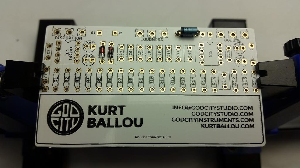
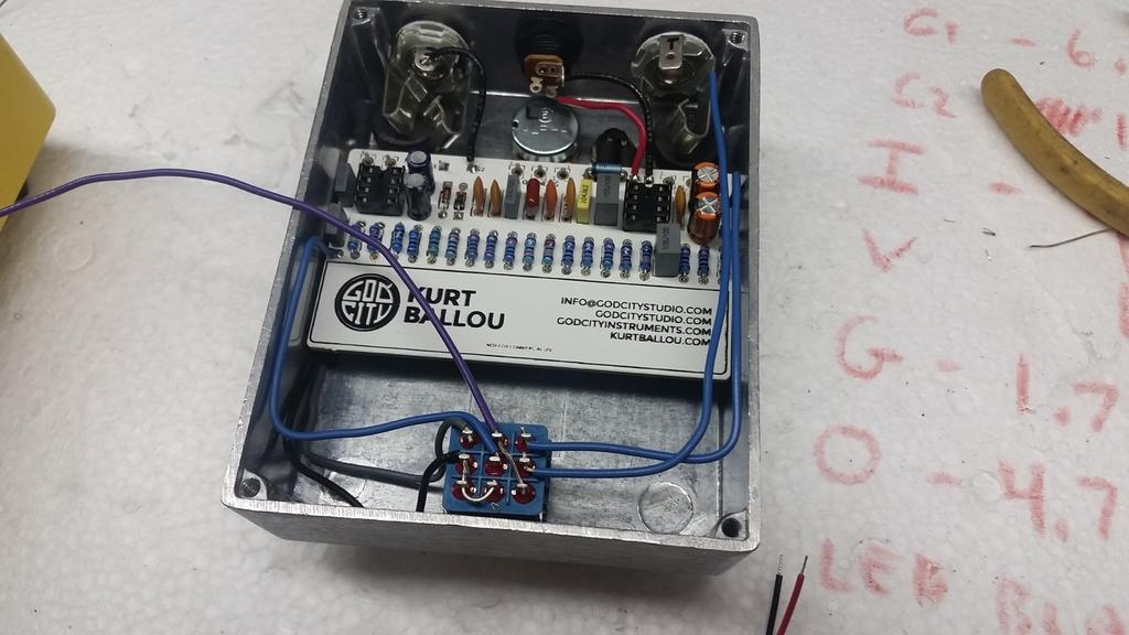
8 NOTE: These instructions refer to the Kurt Ballou side of the PCB as the front side. All IC s, diodes, capacitors, and resistors are connected to the front side. When the pedal is completed, this side will still be visible when the back of the enclosure is removed. These instructions refer to the face of the pedal enclosure, where the knobs and switches are as the front side and the removable bottom, where the PCB is located the back side. Note that in the final assembly, the front of the enclosure will face up, and the front of the PCB will face down.

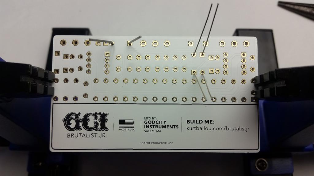
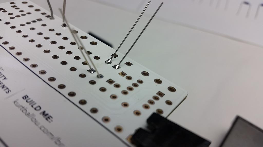
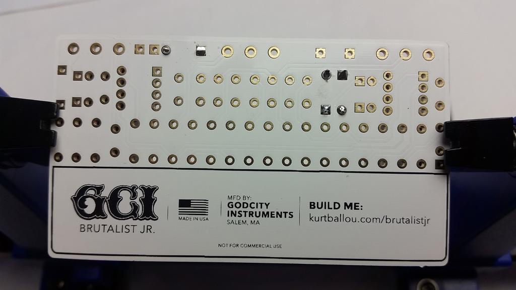
9 POPULATE THE PCB Step 1: Add the diodes. First find the 1N5818 diode. This provides protection against incorrect power supply polarity. Next find a pair of 1N914 diodes. These are the clipping diodes. Bend each diode s legs at 90 degrees and install them through the front side of the PCB. The 1N5818 goes in the D3 slot and the 1N914s go in the D1 and D2 slots. Be sure to match the end of the diode with the stripe to the stripe on the PCB next to the square pad. Proper orientation of diodes is critical. Then, from the back side of the PCB, bend their legs out to hold them in place until it s time to solder. Solder all diodes and trim the excess length of the legs with a side cutter, being sure not to scratch or damage the PCB.
10
11
12
13

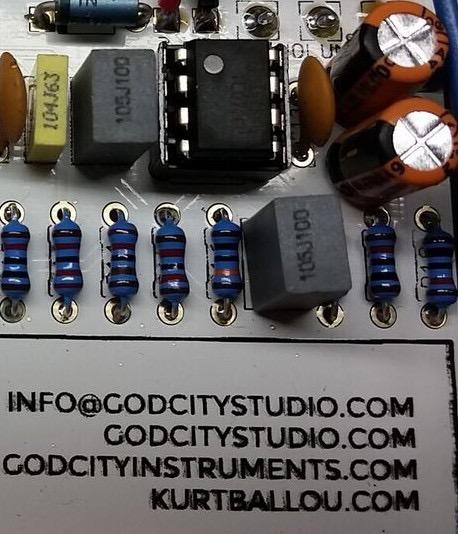
14 Step 2: Add the resistors. These are non-polarized and orientation is not critical. Sort the resistors, then, one by one, bend the legs at the resistor bodies to 90 degrees and insert them into the PCB from the front side. Then, from, the back side, bend their legs out to hold them in place until it s time to solder. Solder all resistors and trim the excess length of the legs with a side cutter, being sure not to scratch or damage the PCB.
15

16

17 Step 3: Add the 8 pin IC sockets. ONLY SOLDER THE SOCKET! The IC s get inserted into the sockets after the sockets had been soldered. Insert the sockets into the PCB from the front side. Then, from the back side, bend their legs out to hold them in place until they are soldered. The notch in the sockets should align with the notches screen printed on the PCB. There will be notches or dots on the ICs that will also align with these notches. Make sure that the ICs are firmly seated in the sockets. Carefully bend the legs in to align with the socket if necessary. Again, DO NOT SOLDER THE ICs.
18

19 Step 4: Add the film and the ceramic disc capacitors. These are non-polarized and orientation is not critical. Sort the capacitors and, one by one, insert them to the PCB from the front side. Then, from the back side, bend their legs out to hold them in place until it s time to solder. Solder all capacitors and trim the excess length of the legs with a side cutter, being sure not to scratch or damage the PCB.

20

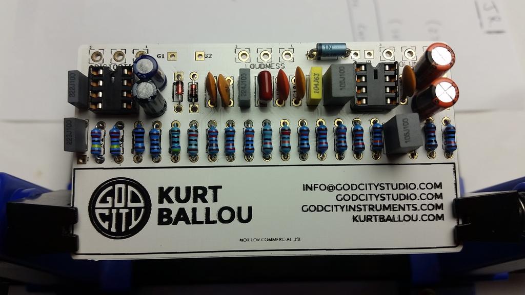
21 Step 5: Add the electrolytic capacitors. These are polarized, which means the orientation is critical. The positive side will have a longer lead and goes into the square solder pad. The negative side will have a shorter lead and a stripe running along the side of the cap, and goes into the round solder pad. Sort the capacitors then, one by one, insert them to the PCB from the front side. Then, from the back side, bend their legs out to hold them in place until it s time to solder. Solder all capacitors and trim the excess length of the legs with your side cutter, being sure not to scratch or damage the PCB.
22

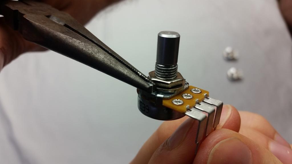
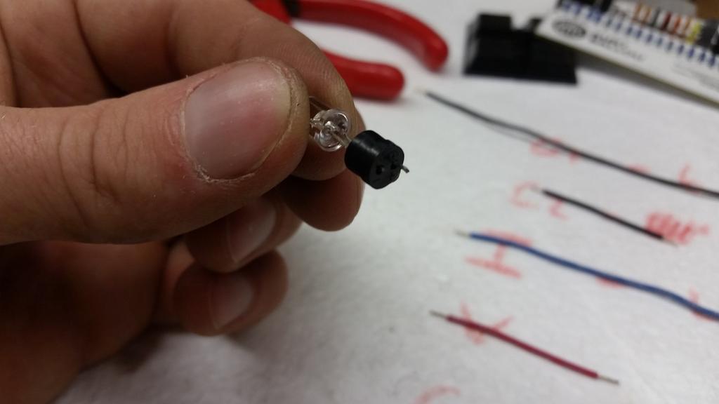
23 Step 6: Potentiometers: The potentiometers will have a small metal tab sticking out of the top of their bodies. Snap these tabs off with a pair of needle nose pliers. The potentiometers will not fit in the enclosure properly with these tabs still attached. Identify each pot at label each with a V, L, and D for Volume, Loudness, and Distortion to ensure they don t get put into the enclosure or board in the wrong order. The circuit will not operate properly if the wrong pots are used in the wrong locations. Test fit the potentiometer in the board but DO NOT SOLDER THE POTENTIOMETERS IN AT THIS TIME.
24

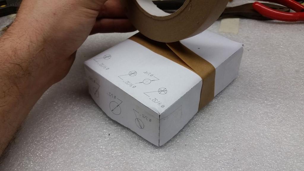
25 PREPARE THE ENCLOSURE Step 1: Print the paper drill template PDF at 1:1 and attach it to the enclosure as described on the drill template. You may find it helpful to tape the template in place before center punching the holes.
26
 and hammer to create divots at the center")
27 Step 2: Put on work gloves. Step 3: Use a center punch (or sharp nail) and hammer to create divots at the center points of the holes. Remove, but do not discard paper template.

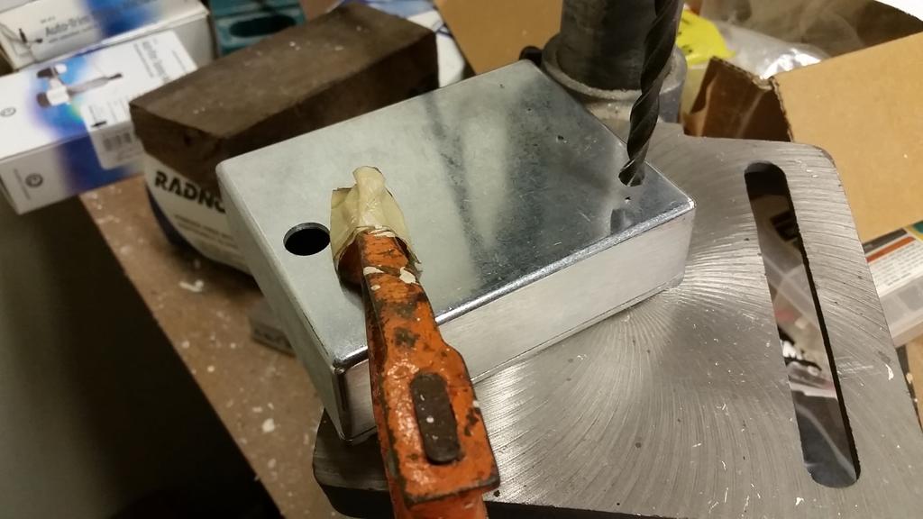
28 Step 4: Drill using the divots as starting points to ensure that the drill doesn t walk off center. Brace the enclosure while drilling to prevent the enclosure from spinning around if the drill catches.
29

30 Step 5: Use a countersink, if necessary, to de-burr the holes. Step 6: Add paint, labeling, and/or artwork.

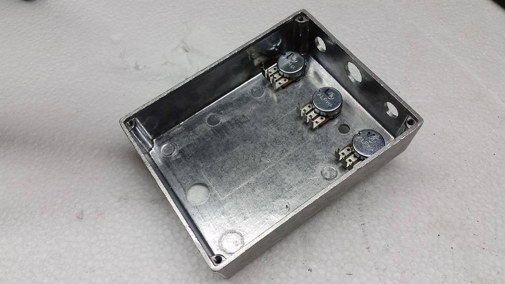
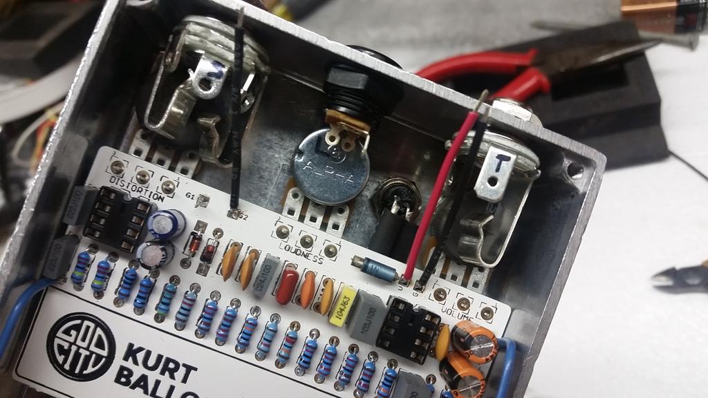
31 ASSEMBLY Gather all of the remaining hardware, the populated PCB, and the finished and drilled enclosure. It is time to assemble. As hardware is added to the enclosure, tighten each with a pair of pliers or appropriate size socket. Step 1: Install the potentiometers into the enclosure from the back (inside.) Pin 3 (see diagram below) of the potentiometer should be toward the left with all 3 pins facing the bottom of the enclosure where the footswitch will be mounted. When the PCB is installed, it will hang off of the potentiometers such that they are still visible. DON T INSTALL THE PCB YET!
32
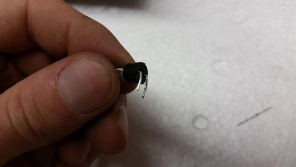
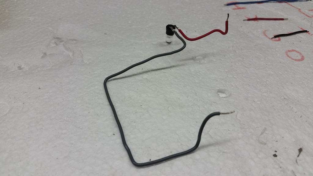
33 Step 2: Locate and install the LED bezel from the front of the enclosure. Note that it has a small, round, plastic base with two holes marked (+) and (-) for the positive and negative leads of the LED. Locate the LED and notice that one leg is longer than the other. The longer leg is the (+) positive lead. Slide the two legs through the plastic base with the correct orientation so that the (+) positive lead goes through the (+) positive hole on it. Once the legs are through, bend the leads together so that they are 90 degrees from their original position. Next, solder a 2.5 section of red wire to the long (+) leg, close to the LED lens but not touching it. Solder a 7.5 section of black wire to the short (-) leg, close to the LED lens but not touching it. Do not let the legs touch or create a solder bridge between them. Trim the excess length from the legs. If needed, two small pieces of tube shrink can be used to cover both exposed leads to ensure contact won t be made between them. DO NOT SNAP THE LED/WIRING INTO THE BEVEL YET.
34
35
36

37 Step 3: Install the power jack through the enclosure and tighten the nut from the inside. Be careful to not over tighten as the plastic threads could strip. Step 4: Install the 3pdt footswitch. Orientation is important. There will be a notch in the threads of the switch. This notch should point at the potentiometers. Also the solder tabs of the switch should be horizontal when viewed from the back. Be sure to double check against the wiring diagram before wiring.

38 Step 5: Install the audio jacks. The stereo jack will be the input jack and will go to the left when looking at the back of the enclosure. This jack has 3 solder tabs. The mono jack will be the output jack and will go to right when looking at the back of the enclosure. This jack has 2 solder tabs.
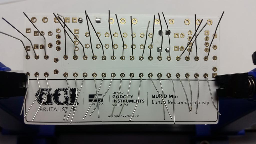
39 Step 6: Time for wiring. Ground wires (G, G1, G2) will be black, power wires (V) will be red and signal wires (I,O) can be any color that is not red or black to avoid confusion. Cut the following lengths of wire: G1 6.5 G I 4 V 1.75 G 1.75 O 4.75 Solder the lengths of wire to the solder pads on the PCB marked I, G, G1, G2, V and O. Note that G1 should be soldered into the back side of the PCB as this wire will run underneath the PCB on its way to the footswitch. Using wire strippers, strip approximately ¼ of shielding off of one end of the wire and tin the end with solder. One at a time, insert the wires through the solder pads from the front of the PCB (EXCEPT FOR G1) and solder them in place from the back of the PCB. Connections to power, jacks and switch will be made inside the enclosure using these wires. Lastly, solder the red wire from the LED to L+ on the PCB from the backside of the PCB.

40
41

42 Step 7: First, install the LED into the bezel. Next, install the PCB on to the potentiometers and solder them in place. PCB should be oriented such that the Kurt Ballou side with all the components faces out. When properly installed all 3 pins of each potentiometer should pass through the PCB. There is no need to bend these pins before soldering and there is no need to trim them after the soldering is completed.
43

44 Step 8: Complete all wiring connections by following the attached wiring diagram. Wires will be trimmed to length as needed, making sure to allow length for the loose end of the wire to be stripped. Do not pull the wires tight during this process as this will put tension on the solder joints and lead to potential failure of the connection. After the wire is trimmed to an appropriate length, using wire strippers, strip approximately ¼ of shielding off of the end of the wire and tin the end with solder. The tinned end can be bent to form a hook, which may make connection to the solder terminals of the switch/jack easier.
45
46

47 Step 9: Install battery, enclosure back and knobs. Knobs will have a small set screw that will need to be tightened with a small flathead screw driver in order to properly operate the potentiometer. Step 10: TEST! If all the instructions were followed and soldering was done carefully, the pedal should be ready for use. Enjoy the Brutalist Jr.!
48 TECH SUPPORT Due to the nature of this project, there is no specialized technical support. Look in the mirror, say to yourself I can do this three times, then try again. If you re still having trouble, ask a friend with building experience. DIY! SUGGESTED MODS If you like tweaking, here s a few places to start. We have not yet tried all of these, so take all these suggestions with a grain of salt. Clipping Diodes: D1 and D2 can be adjusted to produce a variety of changes to the compression, harmonics, and volume of the clipping. LEDs have a larger clipping threshold and will result in less compression and more overall volume. Germanium and Schottky diodes have the lowest clipping threshold and will result in the least amount of overall volume. Mismatching the types of diodes in D1 and D2 creates asymmetric clipping (different clipping thresholds on each half of the AC signal). Do not be afraid to experiment with various clipping diodes to achieve an optimum distortion and/or using toggle switches to allow for multiple clipping options. Red 3mm LED s, 1n4001 s, 1n34a, or nothing at all are common choices. Increasing Maximum Distortion: Increasing the maximum distortion level is optimally achieved by increasing R5. Try doubling or tripling the value to increase the maximum distortion level but be careful as overall noise floor will increase as R5 increases. Op Amp Replacements: Here is a list of op-amps that can replace IC1 and/or IC2: RC4558 NE5532 OPA2134
49 TL082 Generally any op-amp that is pin compatible with a TL072 could be swapped into the circuit. However, be mindful that very high performance op-amps may not be the best choice. They generally require more careful PCB design than is afforded in this kit. Global Treble Adjustment: C13 is used to control the final treble response of the circuit. Increasing the value will darken the overall tone while decreasing the value will brighten the tone. Try values between 100p and 470p. Loudness Treble Adjustment: C10 (in part) adjusts the high shelf of the Loudness control. Increasing the value will shift the center frequency down while decreasing the value shifts the frequency up. Try values between 100p and 470p. Loudness Bass Adjustment: C8 (in part) adjusts the low shelf of the Loudness control. Increasing the value will shift the center frequency down while decreasing the value shifts the frequency up. Lowering this frequency may make the pedal better suited for bass guitar or provide a scooped effect to the EQ on guitar. C7 can be used to lower the overall bass level. Decreasing the value will decrease the overall bass response. Increasing it will increase the bass but above 1uF the returns are diminishing. High Pass Filtering: There are two RC pairs that control bass cut-off, the first of which is R4/C3, the second of which is R6/C5. Reduce the value of these capacitors will increase bass roll off and make for a tighter playing response, albeit thinner sound. However, increasing the bass response in the Loudness control can compensate for a loss of bass in the high pass filter. Try between 4.7 and 33uF for C3 and between 4.7uF and 47uF for C5. Response Mod: Replace R6 with a potentiometer. Aside from affecting the high pass filter, R6 also has an effect on gain. By sweeping the R6 pot in one direction, high pass filtering and gain will increase simultaneously, possibly making the pedal better suited for tight heavy metal rhythm playing. By sweeping in the other direction, bass increases while gain decreases, making the pedal bigger and looser sounding. Try a 1k reverse log pot in series with a 47 ohms resistor.
50 WIRING DIAGRAM
51
Value Location Qty Potentiometers C1M Distortion 1 A10k Volume 1. Footswitch 3PDT SW1 1. Jacks 1/4 Mono 2 DC Power 1
 Distortion BUILD INSTRUCTIONS Thank you for your purchase of our Distortion+ kit! We have completely redesigned our entire line of kits to be the most user friendly, while still maintaining their same
Value Location Qty Transistors 2N5485 Q1, Q2, 4 Q3, Q4 2N5087 Q5 1. Trim Pots 250k VTRIM 1. Potentiometers C500k Speed 1. Toggle Switch On/On Vibe 1
 P-90 BUILD INSTRUCTIONS Thank you for your purchase of our P-90 kit! We have completely redesigned our entire line of kits to be the most user friendly, while still maintaining their same great sound!
Guitarpedalkits.com Overdrive Pedal Build Instructions
 Page 1 Guitarpedalkits.com Overdrive Pedal Build Instructions Follow the instructions in this guide to build your very own DIY overdrive pedal from GuitarPedalKits.com. If you re a first time builder,
Build Your Own Clone Mouse Kit Instructions
 Build Your Own Clone Mouse Kit Instructions Warranty: BYOC, Inc. guarantees that your kit will be complete and that all parts and components will arrive as described, functioning and free of defect. Soldering,
Build Your Own Clone Crown Jewel Kit Instructions
 Build Your Own Clone Crown Jewel Kit Instructions Warranty: BYOC, Inc. guarantees that your kit will be complete and that all parts and components will arrive as described, functioning and free of defect.
Build Your Own Clone Chancellor Kit Instructions
 Build Your Own Clone Chancellor Kit Instructions Warranty: BYOC, Inc. guarantees that your kit will be complete and that all parts and components will arrive as described, functioning and free of defect.
Build Your Own Clone B.G. Fuzz Kit Instructions
 Build Your Own Clone B.G. Fuzz Kit Instructions Warranty: BYOC, Inc. guarantees that your kit will be complete and that all parts and components will arrive as described, functioning and free of defect.
Build Your Own Clone Kuzco Jr. Kit Instructions
 Build Your Own Clone Kuzco Jr. Kit Instructions Warranty: BYOC, Inc. guarantees that your kit will be complete and that all parts and components will arrive as described, functioning and free of defect.
Build Your Own Clone The Swede Kit Instructions
 Build Your Own Clone The Swede Kit Instructions Warranty: BYOC, Inc. guarantees that your kit will be complete and that all parts and components will arrive as described, functioning and free of defect.
Build Your Own Clone Green Pony Kit Instructions
 Build Your Own Clone Green Pony Kit Instructions Warranty: BYOC, Inc. guarantees that your kit will be complete and that all parts and components will arrive as described, functioning and free of defect.
Build Your Own Clone 27V Boost Kit Instructions
 Build Your Own Clone 27V Boost Kit Instructions Warranty: BYOC, Inc. guarantees that your kit will be complete and that all parts and components will arrive as described, functioning and free of defect.
Build Your Own Clone Silver Pony 2 Kit Instructions
 Build Your Own Clone Silver Pony 2 Kit Instructions Warranty: BYOC, Inc. guarantees that your kit will be complete and that all parts and components will arrive as described, functioning and free of defect.
BYOC Vibrato Kit Instructions BA6110 version
 BYOC Vibrato Kit Instructions BA6110 version Please read these instructions very thoroughly before building even if you are an experience builder. Because of the
BYOC Vibrato Kit Instructions BA662A version
 BYOC Vibrato Kit Instructions BA662A version Please read these instructions very thoroughly before building even if you are an experience builder. Because of the layout, there is a certain order which
Build Your Own Clone Silver Pony Kit Instructions
 Build Your Own Clone Silver Pony Kit Instructions Warranty: BYOC, Inc. guarantees that your kit will be complete and that all parts and components will arrive as described, functioning and free of defect.
Build Your Own Clone Li l Comp Kit Instructions
 Build Your Own Clone Li l Comp Kit Instructions Warranty: BYOC, Inc. guarantees that your kit will be complete and that all parts and components will arrive as described, functioning and free of defect.
STEP 0 Prepare the Materials.
 How to Build a Germanium Fuzz Guitar Effect. This document will guide you to build and test your Germanium Fuzz guitar pedal. With all the materials on hand, it takes around 2-4 hours to build it. Try
THE AGGRESSOR (K-995)
") THE AGGRESSOR (K-99) TONE VOLUME DISTORTION MID-SHIFT SWITCH LED The Aggressor Distortion Pedal Modkitsdiy.com 9 VDC CENTER (-) ADAPTER TO AMP IN FROM GUITAR OUT Unplug when not in use to save battery
THE AGGRESSOR (K-99) TONE VOLUME DISTORTION MID-SHIFT SWITCH LED The Aggressor Distortion Pedal Modkitsdiy.com 9 VDC CENTER (-) ADAPTER TO AMP IN FROM GUITAR OUT Unplug when not in use to save battery
Build Your Own Clone Spring Reverb Kit Instructions
 Build Your Own Clone Spring Reverb Kit Instructions Warranty: BYOC, Inc. guarantees that your kit will be complete and that all parts and components will arrive as described, functioning and free of defect.
Build Your Own Clone Li l Echo Kit Instructions
 Build Your Own Clone Li l Echo Kit Instructions Warranty: BYOC, Inc. guarantees that your kit will be complete and that all parts and components will arrive as described, functioning and free of defect.
Build Your Own Clone British Blues Overdrive Kit Instructions
 Build Your Own Clone British Blues Overdrive Kit Instructions Warranty: BYOC, LLC guarantees that your kit will be complete and that all parts and components will arrive as described, functioning and free
Build Your Own Clone Reverb Kit Instructions
 Build Your Own Clone Reverb Kit Instructions Warranty: BYOC, LLC guarantees that your kit will be complete and that all parts and components will arrive as described, functioning and free of defect. Soldering,
Build Your Own Clone Classic Overdrive Kit Instructions
 Build Your Own Clone Classic Overdrive Kit Instructions Warranty: BYOC, LLC guarantees that your kit will be complete and that all parts and components will arrive as described, functioning and free of
Build Your Own Clone Li l Analog Chorus Kit Instructions
 Build Your Own Clone Li l Analog Chorus Kit Instructions Warranty: BYOC, Inc. guarantees that your kit will be complete and that all parts and components will arrive as described, functioning and free
Build Your Own Clone Li l Reverb Kit Instructions
 Build Your Own Clone Li l Reverb Kit Instructions Warranty: BYOC, Inc. guarantees that your kit will be complete and that all parts and components will arrive as described, functioning and free of defect.
Build Your Own Clone Li l Pony Kit Instructions
 Build Your Own Clone Li l Pony Kit Instructions Warranty: BYOC, Inc. guarantees that your kit will be complete and that all parts and components will arrive as described, functioning and free of defect.
Build Your Own Clone Tremolo Kit Instructions
 Build Your Own Clone Tremolo Kit Instructions Warranty: BYOC, LLC guarantees that your kit will be complete and that all parts and components will arrive as described, functioning and free of defect. Soldering,
Build Your Own Clone Analog Chorus Kit Instructions
 Build Your Own Clone Analog Chorus Kit Instructions Warranty: BYOC, Inc. guarantees that your kit will be complete and that all parts and components will arrive as described, functioning and free of defect.
Build Your Own Clone Classic Phaser Kit Instructions
 Build Your Own Clone Classic Phaser Kit Instructions Warranty: BYOC, Inc. guarantees that your kit will be complete and that all parts and components will arrive as described, functioning and free of defect.
THE THUNDERDRIVE (K-950)
") THE THUNDERDRIVE (K-950) OUTPUT DISTORTION Unplug when not in use to save battery life. TO AMP IN The Thunderdrive Modkitsdiy.com FROM GUITAR OUT Use these instructions to learn: How to build an effects
THE THUNDERDRIVE (K-950) OUTPUT DISTORTION Unplug when not in use to save battery life. TO AMP IN The Thunderdrive Modkitsdiy.com FROM GUITAR OUT Use these instructions to learn: How to build an effects
Rangemaster Treble Booster Kit Building Manual
 Rangemaster Treble Booster Kit Building Manual Effect Pedal Kits: Rangemaster Treble Booster The Dallas Rangemaster is the most famous treble booster effect pedal, and it was the first pedal of its kind.
Pacific Antenna Code Practice Oscillator Kit
 Pacific Antenna Code Practice Oscillator Kit This kit is offered to initiate the first time builder in the various techniques of mechanical and electronic kit construction. At the end of the approximately
DC Motor. Controller. User Guide V0210
 DC Motor Controller User Guide 59757 V0210 This kit provides a great exercise of intermediate soldering skills and creates a device that enables you to control various Pitsco motors, Tamiya gearboxes,
THE RING RESONATOR (K-975)
") THE RING RESONATOR (K-975) OUTPUT BOOST The Ring Resonator An Octave Up Fuzz Modkitsdiy.com 9 VDC CENTER (-) ADAPTER TO AMP IN FROM GUITAR OUT Unplug when not in use to save battery life. Use these instructions
THE RING RESONATOR (K-975) OUTPUT BOOST The Ring Resonator An Octave Up Fuzz Modkitsdiy.com 9 VDC CENTER (-) ADAPTER TO AMP IN FROM GUITAR OUT Unplug when not in use to save battery life. Use these instructions
Starving Student II. Starving Student II. SS2 guide. Written By: 6L guides.diyaudio.com/ Page 1 of 24
 SS2 guide Written By: 6L6 2019 guides.diyaudio.com/ Page 1 of 24 INTRODUCTION This is a build guide for the hybrid headphone/pre-amplifier. You can buy a kit at the SSII product listing on the diyaudio
Building the Toothpick Audio CW Filter
 Building the Toothpick Audio CW Filter Introduction The toothpick is a simple variable bandpass audio filter designed to compliment the Splinter QRPp Trans-Receiver. The filter also contains an audio amplifier
Build Your Own Clone Mega Chorus & Vibrato Kit Instructions
 Build Your Own Clone Mega Chorus & Vibrato Kit Instructions Warranty: BYOC, Inc. guarantees that your kit will be complete and that all parts and components will arrive as described, functioning and free
Telecaster Wiring Kits Please Read All Instructions Before Beginning. Tools you will need: Soldering tips: Removing Current Wiring: Step 1. Step 2.
 Telecaster Wiring Kits Please Read All Instructions Before Beginning. Tools you will need: Soldering Iron (35 watt preferably) Solder Wet Sponge Wire Clippers Wire Strippers 3/8 Drill Bit 5/32 Drill Bit
Build Your Own Clone Li l Beaver (Ram s Head) Kit Instructions
 Kit Instructions") Build Your Own Clone Li l Beaver (Ram s Head) Kit Instructions Warranty: BYOC, Inc. guarantees that your kit will be complete and that all parts and components will arrive as described, functioning and
Build Your Own Clone Li l Beaver (Ram s Head) Kit Instructions Warranty: BYOC, Inc. guarantees that your kit will be complete and that all parts and components will arrive as described, functioning and
Easy Transmitter. Support ETX_REV5_Manual V2.7 Revised
 Easy Transmitter Introduction The Easy Transmitter kit from qrpkits.com provides a basic, crystal controlled transmitter with VXO tuning to provide a small tuning range around the crystal frequency. It
Build Your Own Clone Parametric Multi-Band Compressor Kit Instructions
 Build Your Own Clone Parametric Multi-Band Compressor Kit Instructions Warranty: BYOC, Inc. guarantees that your kit will be complete and that all parts and components will arrive as described, functioning
MICROGRANNY v2.1 - Assembly Guide
 last update: 9. 5. 2017 MICROGRANNY v2.1 - Assembly Guide bastl-instruments.com INTRODUCTION Welcome to the assembly guide for the MicroGranny kit. MicroGranny is a monophonic granular sampler by Bastl
THE TRILL TREMOLO (K-960)
") THE TRILL TREMOLO (K-60) DEPTH SPEED The Trill Tremolo Modkitsdiy.com Unplug when not in use to save battery life. TO AMP IN FROM GUITAR OUT Use these instructions to learn: How to build an effects pedal
THE TRILL TREMOLO (K-60) DEPTH SPEED The Trill Tremolo Modkitsdiy.com Unplug when not in use to save battery life. TO AMP IN FROM GUITAR OUT Use these instructions to learn: How to build an effects pedal
THE STEP LADDER (K-978)
") THE STEP LADDER (K-978) Footswitch True-bypass = 0 db OUTPUT INPUT Ground shunt switching on the input jack keeps the amp quiet when unplugged from the Step Ladder. Attenuator Pot Full clockwise = 0 db
THE STEP LADDER (K-978) Footswitch True-bypass = 0 db OUTPUT INPUT Ground shunt switching on the input jack keeps the amp quiet when unplugged from the Step Ladder. Attenuator Pot Full clockwise = 0 db
Explorer Wiring Kit (assembled)
") Explorer Wiring Kit (assembled) For Vintage, Firestorm & Standard Series Please Read All Instructions Before Beginning. Tools you will need: Soldering Iron (35 watt preferably) Solder Wet Sponge Wire Clippers
Explorer Wiring Kit (assembled) For Vintage, Firestorm & Standard Series Please Read All Instructions Before Beginning. Tools you will need: Soldering Iron (35 watt preferably) Solder Wet Sponge Wire Clippers
Chunky Cheese Build Guide Rev
 Chunky Cheese Build Guide Rev. 2008-08-04 The Chunky Cheese is a slightly-modified version of the discontinued Big Cheese fuzz pedal. Table of Contents Table of Contents... 1 PCB Layout... 2 Parts List...
Mono Amplifier. LM386 Headphone Amp
 Mono Amplifier LM386 Headphone Amp Layout On/Off Switch - cuts power to the circuit Mono Input Jack: use either L or R or solder together Schematic Step 1 - Parts List 1.) R1-10ohm Resistor - Brown Black
LED Field Strength Indicator Kit
 LED Field Strength Indicator Kit Description The Field Strength Indicator kit from Qrpkits.com provides a visual way to monitor RF fields through the brightness of an LED. It will respond to RF fields
Read This Page First
 Read This Page First If you are reading this you know the manuals are always available at QRPKITS.com. This is version 8.0 of the manual dated 4/27/2016. There is no need to print out the whole assembly
ABC V1.0 ASSEMBLY IMPORTANT!
 ABC V1.0 ASSEMBLY Before starting this kit, prepare the following tools: Soldering iron (15-20W will do), flush cutters, no.2 hex screwdriver or allen key and phillips screwdriver. Also briefly go through
BUILD YOUR OWN. Fuzz Face SUPER-FREQ.COM
 BUILD YOUR OWN Fuzz Face SUPER-FREQ.COM CHAPTER 1 The Fuzz Face By Mitchell Hudson of super-freq.com, in conjunction with Joe Gore of tonefiend.com. Build your own vintage Fuzz Face! Create a vintage-style
Build Your Own Clone Li l Beaver (Triangle Version) Kit Instructions
 Kit Instructions") Build Your Own Clone Li l Beaver (Triangle Version) Kit Instructions Warranty: BYOC, Inc. guarantees that your kit will be complete and that all parts and components will arrive as described, functioning
Build Your Own Clone Li l Beaver (Triangle Version) Kit Instructions Warranty: BYOC, Inc. guarantees that your kit will be complete and that all parts and components will arrive as described, functioning
LDB-1 Kit Instructions Page 1 of 8
 LDB-1 Kit Instructions Page 1 of 8 Important Information Congratulations and thank you for your purchase of the LDB-1 Little Drummer Boy Analog Drum Machine Kit! Before you start, please read the enclosed
BrewsBySmith.com STC DIY Kit
 BrewsBySmith.com STC-1000 + DIY Kit Contact Information: Greg Smith www.brewsbysmith.com greg@boostbysmith.com I. Hardware Included: STC-1000 flashed with latest software (v1.06 currently) (if purchased)
Pacific Antenna Field Strength Indicator Kit
 Pacific Antenna Field Strength Indicator Kit Description The Field Strength Indicator kit from Pacific Antenna provides a visual way to monitor the presence and relative strength RF fields through the
Assembly and Installation Instructions for White Oak Audio Design PL400 Series 1 LED board
 Thank you for purchasing White Oak Audio Design s Phase Linear PL400 Upgrade LED Light Board. White Oak Audio Design products are meticulously engineered and tested to ensure a direct drop in fit with
Assembly and User Guide
 Assembly and User Guide AtariPunkr is an adjustable stepped tone generator. AtariPunkr provides hours of fun everyone! Powered by: 9V Battery Outputs: Mylar Speaker (Included) Stereo Output (3.5mm Jack)
Assembly and Installation Instructions for White Oak Audio Design TM-1001 LED board
 Thank you for purchasing White Oak Audio Design s TM-1001 Upgrade LED Light Board. White Oak Audio Design products are meticulously engineered and tested to ensure a direct drop in fit with your tuner.
Build Your Own Clone Analog Vibrato Kit Instructions
 Build Your Own Clone Analog Vibrato Kit Instructions Warranty: BYOC, Inc. guarantees that your kit will be complete and that all parts and components will arrive as described, functioning and free of defect.
Bushwacker Jeep Flat Style Fender Flares Front Pair
 Bushwacker Jeep Flat Style Fender Flares Front Pair Note: These instructions involve cutting parts of your vehicle. Please read all instructions prior to starting. Installation Time: 3-4 Hours Tools Required:
Manual Version July 2007
 Manual Version 1.2 - July 2007 Page 1 Table of Contents Section1: M3 Phono Board Build...3 Phono Board Parts List...3 Preparation...4 Fitting the Valve Bases...6 Installing the Resistors...7 Starting the
LunarBlast v1.0. Optical Tremolo. Description:
 LunarBlast v1.0 Optical Tremolo Description: Based on the venerable DIY Tremulus Lune classic circuit, www.madbean.com forum member CultureJam created this awesome sounding tremolo dubbed the Shoot the
Xkitz.com XLO-5CP Control Panel for Five Channel Color Light Organ
 Xkitz.com XLO-5CP Control Panel for Five Channel Color Light Organ Rev 1.15 An Optional accessory for the Xkitz XLO-5 or XLO-5DC 5 Channel Color Light Organs Introduction This kit contains all the electronics
Penrose Quantizer Assembly Guide
 Penrose Quantizer Assembly Guide Schematic and BOM The schematic can be found here: www.sonic-potions.com/public/penrosequantizerschematic.pdf The BOM is available at google docs: Link to BOM Prepare the
Axis Fuzz Kit Building Manual
 Axis Fuzz Kit Building Manual Effect Pedal Kits: Axis Fuzz The Axis Fuzz Kit is based in the Roger Mayer Axis Fuzz, the effect pedal responsible for Jimi Hendrix sound in Axis Bold As Love. What else is
QUAVERATO MIDI MOD. Assembly Instructions
 QUAVERATO MIDI MOD Assembly Instructions 110118 QUAVERATO MIDI MOD Assembly Instructions WHAT YOU WILL NEED...3 WHAT S IN THE BOX...4 POPULATING THE PRINTED CIRCUIT BOARD...7 THE CHASSIS...13 UPDATING
Electric Druid Flangelicious Flanger Project
 Electric Druid Flangelicious Flanger Project (Using either 4KNOBFLANGE or MULTIFLANGE chips) Overview! 2 Build Instructions! 2 Populate the PCB! 2 1N4148 Diodes! 2 Resistors! 2 Cup of tea and soldering
Ultimatum Fuzz. The Ultimate experience in vintage-style octave-up fuzz
 Ultimatum Fuzz The Ultimate experience in vintage-style octave-up fuzz Contents of this document are 2015 Pedal Parts Ltd. No reproduction permitted without the express written permission of Pedal Parts
Circuit Board Assembly Instructions for Babuinobot 1.0
 Circuit Board Assembly Instructions for Babuinobot 1.0 Brett Nelson January 2010 1 Features Sensor4 input Sensor3 input Sensor2 input 5v power bus Sensor1 input Do not exceed 5v Ground power bus Programming
Build Guide CascadiA. GeFet Preamp
 Build Guide CascadiA GeFet Preamp Disclaimery stuff: This project is meant to be assembled by fellow DIYers from the Madbean forum and should only be used for the forces of good. Any other uses prohibited
How To Tame A Wild Mouse
 How To Tame A Wild Mouse By Steve Daniels, President, Small Bear Electronics LLC What's A Wild Mouse? This Wild Mouse is an active tone boost--an amplifier that is tuned with a filter so that it boosts
DIODE / TRANSISTOR TESTER KIT
 DIODE / TRANSISTOR TESTER KIT MODEL DT-100K Assembly and Instruction Manual Elenco Electronics, Inc. Copyright 1988 Elenco Electronics, Inc. Revised 2002 REV-K 753110 DT-100 PARTS LIST If you are a student,
Bill of Materials: PWM Stepper Motor Driver PART NO
 PWM Stepper Motor Driver PART NO. 2183816 Control a stepper motor using this circuit and a servo PWM signal from an R/C controller, arduino, or microcontroller. Onboard circuitry limits winding current,
Electric Druid 4 second Digital Delay Project
 Electric Druid 4 second Digital Delay Project Overview! 2 Build Instructions! 2 Populate the PCB! 2 Resistors! 2 Cup of tea and soldering check! 3 Power protection diode! 4 Ground link wire! 4 IC sockets!
Pacific Antenna Easy Transmitter Kit
 Pacific Antenna Easy Transmitter Kit Introduction The Easy Transmitter kit from qrpkits.com provides a crystal controlled transmitter with VXO tuning. The circuit consists of a N3904 based crystal oscillator
Assembly Instructions for the 1.5 Watt Amplifier Kit
 Assembly Instructions for the 1.5 Watt Amplifier Kit 1.) All of the small parts are attached to a sheet of paper indicating both their value and id. 2.) Leave the parts affixed to the paper until you are
MP573 Assembly guide. Soldering. MP573 Assembly guide PCB split PCB split. Document revision 2.2 Last modification : 22/08/17
 MP573 Assembly guide Safety warning The kits are main powered and use potentially lethal voltages. Under no circumstance should someone undertake the realisation of a kit unless he has full knowledge about
How to build a Cracklebox. Red Wierenga Brooklyn College Center for Computer Music October 13, 2015
 How to build a Cracklebox Red Wierenga Brooklyn College Center for Computer Music October 13, 2015 What s a Cracklebox? What s a Cracklebox? The Cracklebox was developed by Michel Waisvisz and others at
4ms SCM Breakout. Kit Builder's Guide for PCB v2.1 4mspedals.com
 4ms SCM Breakout Kit Builder's Guide for PCB v2.1 4mspedals.com Shuffling Clock Multiplier Breakout This guide is for building a Shuffling Clock Multiplier Breakout module (SCMBO) version 2.1 from the
The Engineer s Thumb Compressor/Limiter ValveWizard PCB User Guide (Issue 3 PCBs)
") The Engineer s Thumb Compressor/Limiter ValveWizard PCB User Guide (Issue 3 PCBs) Fig. 1: Circuit schematic Fig. 2: Component layout Fig. 3: Wiring diagram (with millennium bypass) Before populating the
The Engineer s Thumb Compressor/Limiter ValveWizard PCB User Guide (Issue 3 PCBs) Fig. 1: Circuit schematic Fig. 2: Component layout Fig. 3: Wiring diagram (with millennium bypass) Before populating the
Bill of Materials: Metronome Kit PART NO
 Metronome Kit PART NO. 2168325 The metronome kit allows you to build your own working electronic metronome. Features include a small speaker, flashing LED, and the ability to switch between several different
Balanced Modulator. Model 9748 Assembly and Using Manual PAiA Corporation
 Balanced Modulator Model 9748 Assembly and Using Manual This second-generation 9700-series processing element for modular sound synthesizers is designed to provide great sound and excellent value. Audio
TS500 Assembly guide. Soldering. TS500 Assembly guide Main PCB 1. Diodes. Document revision 1.2 Last modification : 17/12/16
 TS500 Assembly guide Safety warning The kits are main powered and use potentially lethal voltages. Under no circumstance should someone undertake the realisation of a kit unless he has full knowledge about
Lighthouse Beginner s soldering kit
 Lighthouse Beginner s soldering kit Kit contains: 1 x 220 ohm resistor (Red, Red, Black) 1 x 82k ohm resistor (Grey, Red, Orange) 2 x 220k ohm resistors (Red, Red, Yellow) 2 x Diodes 1 x Power switch 1
Glue Fuzz Mounting instructions.
 Glue Fuzz Mounting instructions. Index Important notice. 2 What's in the kit? 3 What you'll need. 4 Soldering on the pcb. 4 Wiring the pedal. 11 Test the board. 12 Debugging chapter. 13 Copyright Zorg
Instructions for Building the Pulsed Width Modulation Circuit. MC-12 (DC Motor Controller or PWM) From Electronic Light Inc. (revised kit 10/03/08)
 From Electronic Light Inc. (revised kit 10/03/08)") Instructions for Building the Pulsed Width Modulation Circuit MC-12 (DC Motor Controller or PWM) From Electronic Light Inc. (revised kit 10/03/08) Congratulations on your purchase of the MC-12 DC Motor
Instructions for Building the Pulsed Width Modulation Circuit MC-12 (DC Motor Controller or PWM) From Electronic Light Inc. (revised kit 10/03/08) Congratulations on your purchase of the MC-12 DC Motor
IR add-on module circuit board assembly - Jeffrey La Favre January 27, 2015
 IR add-on module circuit board assembly - Jeffrey La Favre January 27, 2015 1 2 For the main circuits of the line following robot you soldered electronic components on a printed circuit board (PCB). The
Jour de FET Mounting instructions.
 Jour de FET Mounting instructions. Summary Important notice. What's in the kit? What you'll need. Soldering on the pcb. Wiring the pedal. Test the board. Debugging chapter. Hacks!!! 3 4 4 3 5 6 Copyright
The ability to make basic voltage and resistance measurements using a digital multimeter
 Congratulations on your purchase of a new OneShot chassis! The PC01 OneShot combines a rugged enclosure, power supply, and discrete instrument DI in a compact 1/4U package. A few minutes of assembly are
VC Divider Assembly manual
 1 VC Divider Assembly manual Thank you for your purchase of the SSSR Labs VC Divider DIY Kit! This manual will help you assemble the VC Divider quickly and easily. Follow the instructions! As you may know,
Building the Sawdust Regenerative Receiver
 Building the Sawdust Regenerative Receiver Introduction The Sawdust is a super regenerative receiver using the basic Armstrong design architecture. The receiver uses one toroidal transformer to provide
Assembly and Installation Instructions for White Oak Audio Design PL700B LED board
 Thank you for purchasing White Oak Audio Design s Phase Linear PL700B Upgrade LED Light Board. White Oak Audio Design products are meticulously engineered and tested to ensure a direct drop in fit with
KASTLE v1.5 - Assembly Guide
 last update: 14. 12. 2017 KASTLE v1.5 - Assembly Guide bastl-instruments.com INTRODUCTION Welcome to the assembly guide for the Kastle kit - mini modular synthesizer. It is suitable for beginners. It is
Never power this piano with anything other than a standard 9V battery!
 Welcome to the exciting world of Digital Electronics! Who is this kit intended for? This kit is intended for anyone from ages 13 and above and assumes no previous knowledge in the field of hobby electronics.
Digital Electronics & Chip Design
 Digital Electronics & Chip Design Lab Manual I: The Utility Board 1999 David Harris The objective of this lab is to assemble your utility board. This board, containing LED displays, switches, and a clock,
Repairing Microsoft Wedge Touch Mouse Battery Cover Retaining Clip
 Repairing Microsoft Wedge Touch Mouse Battery Cover Retaining Clip Disassembly, repair and reassembly of Wedge Touch mouse when the battery cover will not stay closed. Also is a good guide to repair other
Build Your Own Clone Echo Royal Kit Instructions
 Build Your Own Clone Echo Royal Kit Instructions Warranty: BYOC, Inc. guarantees that your kit will be complete and that all parts and components will arrive as described, functioning and free of defect.
Assembly Instructions
 Assembly Instructions For the SSQ-2F 3.1 MHz Rife Controller Board Kit v1.41 Manual v1.00 2012 by Ralph Hartwell Spectrotek Services GENERAL ASSEMBLY INSTRUCTIONS Arrange for a clean work surface with
Custom Front Panel Upgrade Instructions
 Custom Front Panel Upgrade Instructions Here are the directions for upgrading your SP-II to an SP-IIB, with a custom blackanodized front panel and engraved lettering. There are only forty SP-IIB s in existence
Standard Kit #1 (3-way switch)
") Standard Kit #1 (3-way switch) Please Read All Instructions Before Beginning. Tools you will need: Soldering Iron (35 watt preferably) Solder Wet Sponge Wire Clippers 3/8 Drill Bit 1/4 Drill Bit Variable
Standard Kit #1 (3-way switch) Please Read All Instructions Before Beginning. Tools you will need: Soldering Iron (35 watt preferably) Solder Wet Sponge Wire Clippers 3/8 Drill Bit 1/4 Drill Bit Variable