Chapter 8. Piping Isometrics
|
|
|
- Dennis Copeland
- 5 years ago
- Views:
Transcription
1 Chapter 8 Piping Isometrics
2 An isometric drawing is a type of pictorial drawing in which three sides of an object can be seen in one view. It s popular within the process piping industry because it can be laid out and drawn with ease and portrays the object in a realistic view. Sometimes it is used in lieu of plans and elevations but typically it is used to supplement the plan drawings Isometrics are used as fabrication & shop drawings for pipe run fabrication Isometrics also provide a drafter with the ability to calculate angular offsets in the pipe run.
3 Isometric Layout: Isometric lines: one vertical & two at 30 from horizontal Isometric lines can be measured Non-isometric lines: lines NOT parallel to the isometric lines these lines cannot be measured Example of isometric axis You will use the isometric axis on ALL of your isometric drawings! In the example at left, note that all directions of the pipe match the three isometric axis lines
4 Scale: isometrics are rarely drawn to scale however, pipe lengths should be shown proportionately many companies draw isometrics on B-size paper (11 x 17 ) which is a limited space so sometimes proportion may be sacrificed it s IMPORTANT that the written dimensions are accurate Direction & location: location and direction help to properly orient the isometric drawing a north arrow give direction and should ALWAYS point to the upper-right corner of the paper structural reference points that provide location can be shown on isometric dimensions MUST always be given to points of reference; such as structures, existing equipment etc coordinates should also be shown on the isometric drawing
5 Fitting symbols and orientation: when orienting fittings and valves it s important to know that there are good methods and poor methods in this orientation process the general rule for producing an isometric using GOOD techniques, is to draw the fittings so they are parallel to the last direction change or branch in the pipe Not following the general rule leads to a chaotic looking isometric it doesn t look professional
6 fittings are drawn the same shape as they appear on the plan & elevation drawings EXCEPT they re at an isometric angle elbows can be drawn a couple of ways check with company standards In this class we will use square corner elbows not only is this the most typical method used, but it s also quicker to draw. Curved Elbow Representation Squared Elbow Representation
7 Connected piping: one run of pipe per isometric drawing branches of the pipe run or continuations are placed on other drawings typically shown as short portion of dashed line on main pipe run usually a note indicates the name or specification of the branch line existing piping is sometimes shown using double line method or dashed lines in this class we will use dashed lines either method is useful in that it distinguishes new pipe from existing piping Notice spec change between new and existing pipe & note for reference drawing Example of double-line method showing existing piping Pg. 220 text Dashed line showing pipe continuation and note providing reference drawing information.
8 Isometric drawing techniques: To increase drawing efficiency: Create a prototype for isometric drawings set up grid, snap, isometric plane orientation, border and title block, BOM, text styles & dimension settings Develop library of isometric symbols valves, fittings, instruments, equipment common drawing components Create dimension styles in all three isometric planes Construct menus that you can pick symbols from
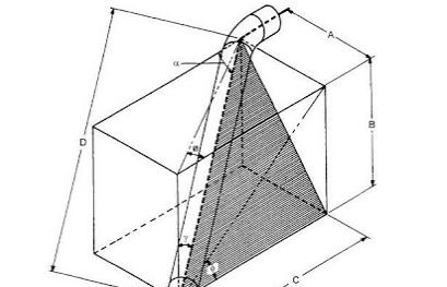
9 Drawing Isometric Offsets: Offset: indicates that a piece of pipe is shifted from one line of direction to another is done with a fitting (typically a 45 elbow) one of the few times you might have artistic license in making a piping drawing Horizontal offsets: If you draw a horizontal pipe with a 45 If you draw a horizontal pipe with a 45 elbow running form southeast to northwest technically correct, it would look like a vertical line to prevent confusion, the offset is drawn 22 ½ from vertical to give the illusion of the angle.


10 That s why many companies use a squaring-in plane within the plane of the offset Vertical Offsets: These offsets can get just as confusing as the horizontal offsets.
11 Calculating Isometric Offsets Although you can get away with an educated guess as to making an angular offset easy to see when laying out an isometric, you can t make a guess-ti-mate when it comes to determining pipe lengths and angles. So, pull out the old calculator, paper, pencil & a BIG eraser and let s get started. The basic calculations any pipe drafter uses are those involving trigonometry and right angles. Pythagoras, a 6 th century B.C. Greek philosopher, came up with a way to deal with calculations involving right angles and it s called the anyone?. Anyone??? Pythagorean Theorem Simply, what Pythagoras concluded was that when working with right angle triangles the square of the hypotenuse is equal to the sum of the squares of the two sides. c² = a² + b²
12 Example: Pythagorean Theorem (p. 223) 1. Start off with what s given or what you can determine from the pipe drawing itself. a) We are given an 45 angle rise, that clues us in on the fact that the two sides of our triangle are going to be the same length b) By doing simple subtraction, we can come up with the length for side B: 11-9 ¼ 6-3 = 5-6 ¼ OR you can subtract the elevations given and get the same dimension for side A. c) Since B = A: side A = 5-6 ¼ as well. BREAKING DOWN THE NUMBERS: FYI: 5-6 ¼ = 5.0 ft. = ft. 6 = 6/12 =.5 in. ¼ =.25/12 =.0208 in. 2. Now all you have to do is plug the numbers into your formula: a) c² = (5-6 ¼ )² + (5-6 ¼ )² b) c² = (5.5208)² + (5.5208)² c) c² = d) c² = e) c = f) c = g) c = /16
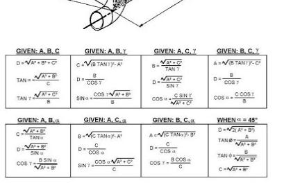
13 TRIG function formulas: There are three basic trig function formulas that are frequently used in piping: SIN = SO/HYP COS = SA/HYP TAN = SO/SA When angle A is used, a is the side opposite (SO) and b is the side adjacent (SA). When angle B is used, a is the side adjacent (SA) and b is the side opposite (SO). Get familiar with the formulas for solving angles and lengths in piping offsets. Table on page 227 in your text.
14 Solving Compound Angles: When piping has to be snaked through equipment, steel, and other pipe, the pipe may be rolled along with the offset. This type of piping design is called a rolling offset and forms a compound angle. Four terms associated with a rolling offset configuration: RUN: Length of total offset in direction of pipe run SET: Depth of offset ROLL: Breadth of offset TRAVEL: True length of pipe through offset
15
16 Feet inch Total (mm) SQ. A C B
17 Isometric Dimensioning & Labeling Two planes are used in dimensioning and labeling-horizontal and vertical. DIMENSIONING PRACTICES: 1. Best way to dimension a pipe is to its centerline at the intersection point 2. Try to keep all dimensions outside the piping view when possible 3. Dimensions should ALWAYS be shown between points in the same plane 4. One of the extension lines of the dimension should be a centerline of the run of pipe 5. Vertical lines of text should always be parallel with extension lines
18 Isometric lettering: Basic guidelines for lettering isometric drawings: 1. If the pipe s vertical, the lettering should be written vertically and at 30 angle 2. If pipe is in horizontal plane, the lettering will appear as if it is lying down and will be oriented on both 30 angles 3. Dimensions appear to be lying down if the pipe is horizontal or standing on end if the pipe is vertical.
THE SINUSOIDAL WAVEFORM
 Chapter 11 THE SINUSOIDAL WAVEFORM The sinusoidal waveform or sine wave is the fundamental type of alternating current (ac) and alternating voltage. It is also referred to as a sinusoidal wave or, simply,
2. Be able to evaluate a trig function at a particular degree measure. Example: cos. again, just use the unit circle!
 Study Guide for PART II of the Fall 18 MAT187 Final Exam NO CALCULATORS are permitted on this part of the Final Exam. This part of the Final exam will consist of 5 multiple choice questions. You will be
Technological Design Mr. Wadowski. Orthographic & Isometric Drawing Lesson
 Technological Design Mr. Wadowski Orthographic & Isometric Drawing Lesson TOPICS Working Drawings, Isometric Drawings & Orthographic Drawings Glass box concept Multiview projection Orthographic projection
Civil Engineering Drawing
 Civil Engineering Drawing Third Angle Projection In third angle projection, front view is always drawn at the bottom, top view just above the front view, and end view, is drawn on that side of the front
Trigonometric identities
 Trigonometric identities An identity is an equation that is satisfied by all the values of the variable(s) in the equation. For example, the equation (1 + x) = 1 + x + x is an identity. If you replace
TERRA Environmental Research Institute
 TERRA Environmental Research Institute MATHEMATICS FCAT PRACTICE STRAND 3 Geometry and Spatial Sense Angle Relationships Lines and Transversals Plane Figures The Pythagorean Theorem The Coordinate Plane
Trigonometry. An Overview of Important Topics
 Trigonometry An Overview of Important Topics 1 Contents Trigonometry An Overview of Important Topics... 4 UNDERSTAND HOW ANGLES ARE MEASURED... 6 Degrees... 7 Radians... 7 Unit Circle... 9 Practice Problems...
Copyrighted Material. Copyrighted Material. Copyrighted. Copyrighted. Material
 Engineering Graphics ORTHOGRAPHIC PROJECTION People who work with drawings develop the ability to look at lines on paper or on a computer screen and "see" the shapes of the objects the lines represent.
Algebra 2/Trigonometry Review Sessions 1 & 2: Trigonometry Mega-Session. The Unit Circle
 Algebra /Trigonometry Review Sessions 1 & : Trigonometry Mega-Session Trigonometry (Definition) - The branch of mathematics that deals with the relationships between the sides and the angles of triangles
Student Instruction Sheet: Unit 4 Lesson 1. Pythagorean Theorem
 Student Instruction Sheet: Unit 4 Lesson 1 Suggested time: 75 minutes Pythagorean Theorem What s important in this lesson: In this lesson you will learn the Pythagorean Theorem and how to apply the theorem
Dimensioning the Rectangular Problem
 C h a p t e r 3 Dimensioning the Rectangular Problem In this chapter, you will learn the following to World Class standards: 1. Creating new layers in an AutoCAD drawing 2. Placing Centerlines on the drawing
How to work out trig functions of angles without a scientific calculator
 Before starting, you will need to understand how to use SOH CAH TOA. How to work out trig functions of angles without a scientific calculator Task 1 sine and cosine Work out sin 23 and cos 23 by constructing
The Pythagorean Theorem
 . The Pythagorean Theorem Goals Draw squares on the legs of the triangle. Deduce the Pythagorean Theorem through exploration Use the Pythagorean Theorem to find unknown side lengths of right triangles
Trigonometry Review Page 1 of 14
 Trigonometry Review Page of 4 Appendix D has a trigonometric review. This material is meant to outline some of the proofs of identities, help you remember the values of the trig functions at special values,
Copyrighted. Material. Copyrighted. Material. Copyrighted. Copyrighted. Material
 Engineering Graphics FREEHAND SKETCHING Introduction to Freehand Sketching Sketching is a very important technique for technical communication. Sketches can transfer ideas, instructions and information
Chapter 2: Pythagoras Theorem and Trigonometry (Revision)
") Chapter 2: Pythagoras Theorem and Trigonometry (Revision) Paper 1 & 2B 2A 3.1.3 Triangles Understand a proof of Pythagoras Theorem. Understand the converse of Pythagoras Theorem. Use Pythagoras 3.1.3 Triangles
Chapter 2: Pythagoras Theorem and Trigonometry (Revision) Paper 1 & 2B 2A 3.1.3 Triangles Understand a proof of Pythagoras Theorem. Understand the converse of Pythagoras Theorem. Use Pythagoras 3.1.3 Triangles
Concept: Pythagorean Theorem Name:
 Concept: Pythagorean Theorem Name: Interesting Fact: The Pythagorean Theorem was one of the earliest theorems known to ancient civilizations. This famous theorem is named for the Greek mathematician and
Math Review Questions
 Math Review Questions Working with Feet and Inches A foot is broken up into twelve equal parts called inches. On a tape measure, each inch is divided into sixteenths. To add or subtract, arrange the feet
Satish Lele M:
 Satish Lele satish.lele@gmail.com M:91-98202 77283 This is a program for Skill Development and Bridging the Gap between Manual and Computer work. I offer Training of Basic Fundamentals and How to Use my
Multi-View Drawing Review
 Multi-View Drawing Review Sacramento City College EDT 300/ENGR 306 EDT 300 / ENGR 306 - Chapter 5 1 Objectives Identify and select the various views of an object. Determine the number of views needed to
3.9. Pythagorean Theorem Stop the Presses. My Notes ACTIVITY
 Pythagorean Theorem SUGGESTED LEARNING STRATEGIES: Marking the Text, Predict and Confirm, Shared Reading Jayla and Sidney are co-editors-in-chief of the school yearbook. They have just finished the final
Modeling an Airframe Tutorial
 EAA SOLIDWORKS University p 1/11 Difficulty: Intermediate Time: 1 hour As an Intermediate Tutorial, it is assumed that you have completed the Quick Start Tutorial and know how to sketch in 2D and 3D. If
MULTIPLE CHOICE. Choose the one alternative that best completes the statement or answers the question.
 Trigonometry Final Exam Study Guide Name MULTIPLE CHOICE. Choose the one alternative that best completes the statement or answers the question. The graph of a polar equation is given. Select the polar
Isometric Drawing (Architectural Board drafting)
") Design and Drafting Description Isometric drawings use perspective to communicate a large amount of information in a single drawing. Isometric drawings show three sides of an object, making it easier to
Design and Drafting Description Isometric drawings use perspective to communicate a large amount of information in a single drawing. Isometric drawings show three sides of an object, making it easier to
Student + Instructor:
 DRAFT OF DEMO FOR The following set of instructions are an optional replacement for the Section Views in SolidWorks. This demo should help prepare the students for the Out of Class HW Student + Instructor:
How to Do Trigonometry Without Memorizing (Almost) Anything
 Anything") How to Do Trigonometry Without Memorizing (Almost) Anything Moti en-ari Weizmann Institute of Science http://www.weizmann.ac.il/sci-tea/benari/ c 07 by Moti en-ari. This work is licensed under the reative
How to Do Trigonometry Without Memorizing (Almost) Anything Moti en-ari Weizmann Institute of Science http://www.weizmann.ac.il/sci-tea/benari/ c 07 by Moti en-ari. This work is licensed under the reative
Sketch-Up Guide for Woodworkers
 W Enjoy this selection from Sketch-Up Guide for Woodworkers In just seconds, you can enjoy this ebook of Sketch-Up Guide for Woodworkers. SketchUp Guide for BUY NOW! Google See how our magazine makes you
1 ISOMETRIC PROJECTION SECTION I: INTRODUCTION TO ISOMETRIC PROJECTION
 1 ISOMETRIC PROJECTION SECTION I: INTRODUCTION TO ISOMETRIC PROJECTION Orthographic projection shows drawings of an object in a two-dimensional format, with views given in plan, elevation and end elevation
Math Labs. Activity 1: Rectangles and Rectangular Prisms Using Coordinates. Procedure
 Math Labs Activity 1: Rectangles and Rectangular Prisms Using Coordinates Problem Statement Use the Cartesian coordinate system to draw rectangle ABCD. Use an x-y-z coordinate system to draw a rectangular
Working with Process Flow DiagramsChapter1:
 Chapter 1 Working with Process Flow DiagramsChapter1: In this chapter, you learn about designing piping with AutoCAD MEP. The design phase consists of conceptualizing, modeling, and documenting the necessary
COMPOUND ROOFS WORKSHOP - Introduction Complex roof geometry is a challenge most framers face eventually. These problems can be solved either
 COMPOUND ROOFS WORKSHOP - Introduction Complex roof geometry is a challenge most framers face eventually. These problems can be solved either mathematically or visually, but the complete carpenter will
CADPIPE Industrial Pipe. Tutorial
 CADPIPE Industrial Pipe Tutorial Introduction This Tutorial is a brief introduction to the power of CADPIPE 3D DESIGN. We will show you a few key features and the general procedures for creating 3D piping
This section will take you through the process of drawing an oblique block. Your entire part, in all views, should look like Figure 1.
 Oblique Block Preface This section will take you through the process of drawing an oblique block. Your entire part, in all views, should look like Figure 1. Figure 1 68 / 3D Scripted Drawings: Oblique
Pythagorean Theorem Unit
 Pythagorean Theorem Unit TEKS covered: ~ Square roots and modeling square roots, 8.1(C); 7.1(C) ~ Real number system, 8.1(A), 8.1(C); 7.1(A) ~ Pythagorean Theorem and Pythagorean Theorem Applications,
Chapter 6 Title Blocks
 Chapter 6 Title Blocks In previous exercises, every drawing started by creating a number of layers. This is time consuming and unnecessary. In this exercise, we will start a drawing by defining layers
Scale and Dimensioning (Architectural Board Drafting)
") Youth Explore Trades Skills Description In this activity, the teacher will first select an object that is larger than the page and scale it to fit in the designated drawing area to explain architectural
Youth Explore Trades Skills Description In this activity, the teacher will first select an object that is larger than the page and scale it to fit in the designated drawing area to explain architectural
Isometric Drawing Chapter 26
 Isometric Drawing Chapter 26 Sacramento City College EDT 310 EDT 310 - Chapter 26 - Isometric Drawing 1 Drawing Types Pictorial Drawing types: Perspective Orthographic Isometric Oblique Pictorial - like
PORTAGE COUNTY WATER RESOURCES DRAFTING STANDARDS. Date: January 26, 2001
 PORTAGE COUNTY WATER RESOURCES DRAFTING STANDARDS Date: January 26, 2001 Portage County Water Resources Drafting Standards. AutoCad 2000/Land Development Desktop R2 Friday, January 26, 2001 Preface: Part
ACT Coordinate Geometry Review
 ACT Coordinate Geometry Review Here is a brief review of the coordinate geometry concepts tested on the ACT. Note: there is no review of how to graph an equation on this worksheet. Questions testing this
Module 2: Radial-Line Sheet-Metal 3D Modeling and 2D Pattern Development: Right Cone (Regular, Frustum, and Truncated)
") Inventor (5) Module 2: 2-1 Module 2: Radial-Line Sheet-Metal 3D Modeling and 2D Pattern Development: Right Cone (Regular, Frustum, and Truncated) In this tutorial, we will learn how to build a 3D model
Inventor (5) Module 2: 2-1 Module 2: Radial-Line Sheet-Metal 3D Modeling and 2D Pattern Development: Right Cone (Regular, Frustum, and Truncated) In this tutorial, we will learn how to build a 3D model
Book 10: Slope & Elevation
 Math 21 Home Book 10: Slope & Elevation Name: Start Date: Completion Date: Year Overview: Earning and Spending Money Home Travel and Transportation Recreation and Wellness 1. Budget 2. Personal Banking
Orthographic Drawing (Architectural Board Drafting)
") Design and Drafting Description In this activity, the teacher will introduce orthographic projection, in which a multi-view drawing shows how the sides of an object are related to each another. Students
Design and Drafting Description In this activity, the teacher will introduce orthographic projection, in which a multi-view drawing shows how the sides of an object are related to each another. Students
Fundamentals III CHAPTER PROJECT EXERCISE
 CHAPTER 4 Fundamentals III PROJECT EXERCISE This project exercise provides point-by-point instructions for setting up the drawing with layers and then creating the objects shown in Figure P4 1. FIGURE
Add labels to the sides...
 Orthographic Drawings Orthographic Projection A projection on a plane, using lines perpendicular to the plane Graphic communications has many forms. Orthographics is one such form. It was developed as
This section will take you through the process of drawing a fixture base. Your entire part, in all views, should look like Figure 1.
 Fixture Base Preface This section will take you through the process of drawing a fixture base. Your entire part, in all views, should look like Figure 1. Figure 1 92 / Scripted 3D Drawings: Fixture Base
Unit Circle: Sine and Cosine
 Unit Circle: Sine and Cosine Functions By: OpenStaxCollege The Singapore Flyer is the world s tallest Ferris wheel. (credit: Vibin JK /Flickr) Looking for a thrill? Then consider a ride on the Singapore
Catty Corner. Side Lengths in Two and. Three Dimensions
 Catty Corner Side Lengths in Two and 4 Three Dimensions WARM UP A 1. Imagine that the rectangular solid is a room. An ant is on the floor situated at point A. Describe the shortest path the ant can crawl
ONE-POINT PERSPECTIVE
 NAME: PERIOD: PERSPECTIVE Linear Perspective Linear Perspective is a technique for representing 3-dimensional space on a 2- dimensional (paper) surface. This method was invented during the Renaissance
We will study all three methods, but first let's review a few basic points about units of measurement.
 WELCOME Many pay items are computed on the basis of area measurements, items such as base, surfacing, sidewalks, ditch pavement, slope pavement, and Performance turf. This chapter will describe methods
Module Guidance Document. Geometry Module 2
 Geometry Module 2 Topic A Scale Drawings 5 days Topic B Dilations 5 days Topic C Similarity and Dilations 15 days Topic D Applying Similarity to Right 7 days Triangles Topic D Trigonometry 13 days Just
Orthographic Drawings
 Orthographic Drawings You don t have to be an artist to draw great furniture plans. By Craig Bentzley W oodworking requires a graphic language to convey building information. We can t do it without drawings
Unit 5. Algebra 2. Name:
 Unit 5 Algebra 2 Name: 12.1 Day 1: Trigonometric Functions in Right Triangles Vocabulary, Main Topics, and Questions Definitions, Diagrams and Examples Theta Opposite Side of an Angle Adjacent Side of
MODELING AND DESIGN C H A P T E R F O U R
 MODELING AND DESIGN C H A P T E R F O U R OBJECTIVES 1. Identify and specify basic geometric elements and primitive shapes. 2. Select a 2D profile that best describes the shape of an object. 3. Identify
ME1105 Engineering Drawing & Design
 City University London Term 1 Assessment 2008/2009 School of Engineering and Mathematical Sciences ME1105 Engineering Drawing & Design Student Name:.., Group: Examination duration: Reading time: This paper
Perspective Sketching
 Perspective Sketching Perspective Drawings A perspective drawing offers the most realistic three-dimensional view of all the pictorial methods, because it portrays the object in a manner that is most similar
THE PYTHAGOREAN SPIRAL PROJECT
 THE PYTHAGOREAN SPIRAL PROJECT A Pythagorean Spiral is a series of right triangles arranged in a spiral configuration such that the hypotenuse of one right triangle is a leg of the next right triangle.
Isometric Drawings. Figure A 1
 A Isometric Drawings ISOMETRIC BASICS Isometric drawings are a means of drawing an object in picture form for better clarifying the object s appearance. These types of drawings resemble a picture of an
CH 21 2-SPACE. Ch 21 2-Space. y-axis (vertical) x-axis. Introduction
 x-axis. Introduction") 197 CH 21 2-SPACE Introduction S omeone once said A picture is worth a thousand words. This is especially true in math, where many ideas are very abstract. The French mathematician-philosopher René Descartes
197 CH 21 2-SPACE Introduction S omeone once said A picture is worth a thousand words. This is especially true in math, where many ideas are very abstract. The French mathematician-philosopher René Descartes
Thinking Irregularly. Timber Framers Guild Eastern Conference Roanoke, Virginia November 9, 2006
 Thinking Irregularly Timber Framers Guild Eastern Conference Roanoke, Virginia November 9, 2006 Basic information Main Roof slope is 9 : 12 Adjacent Roof slope is 10-1/2 : 12 Run of main roof is 12 The
Assignment 12 CAD Mechanical Part 2
 Assignment 12 CAD Mechanical Part 2 Objectives In this assignment you will learn to apply the hidden lines, isometric snap, and ellipses commands along with commands previously learned.. General Hidden
Surveying & Measurement. Detail Survey Topographic Surveying
 Surveying & Measurement Detail Survey Topographic Surveying Introduction Mapping surveys are made to determine the relief of the earth s surface and locate critical points on it. to determine the locations
Geometry For Technical Drawing Chapter 4
 Geometry For Technical Drawing Chapter 4 Sacramento City College EDT 300/ENGR 306 EDT 300/ENGR 306 1 Objectives Identify and describe geometric shapes and constructions used by drafters. Construct various
ORTHOGRAPHIC PROJECTION
 ORTHOGRAPHIC PROJECTION C H A P T E R S I X OBJECTIVES 1. Recognize and the symbol for third-angle projection. 2. List the six principal views of projection. 3. Understand which views show depth in a drawing
Activity 2.4 Multi-view Sketching
 Activity 2.4 Multi-view Sketching Introduction It s a very common occurrence to see a product advertisement and think, I thought of an idea for something like that just a few months ago. People spend a
CHAPTER 01 PRESENTATION OF TECHNICAL DRAWING. Prepared by: Sio Sreymean
 CHAPTER 01 PRESENTATION OF TECHNICAL DRAWING Prepared by: Sio Sreymean 2015-2016 Why do we need to study this subject? Effectiveness of Graphics Language 1. Try to write a description of this object. 2.
Chapter 6: Periodic Functions
 Chapter 6: Periodic Functions In the previous chapter, the trigonometric functions were introduced as ratios of sides of a triangle, and related to points on a circle. We noticed how the x and y values
Circuit Analysis-II. Circuit Analysis-II Lecture # 2 Wednesday 28 th Mar, 18
 Circuit Analysis-II Angular Measurement Angular Measurement of a Sine Wave ü As we already know that a sinusoidal voltage can be produced by an ac generator. ü As the windings on the rotor of the ac generator
UNIT 6: CONJECTURE AND JUSTIFICATION WEEK 24: Student Packet
 Name Period Date UNIT 6: CONJECTURE AND JUSTIFICATION WEEK 24: Student Packet 24.1 The Pythagorean Theorem Explore the Pythagorean theorem numerically, algebraically, and geometrically. Understand a proof
Student Name: Teacher: Date: District: Rowan. Assessment: 9_12 T and I IC61 - Drafting I Test 1. Description: Unit C - Sketching - Test 2.
 Student Name: Teacher: Date: District: Rowan Assessment: 9_12 T and I IC61 - Drafting I Test 1 Description: Unit C - Sketching - Test 2 Form: 501 1. The most often used combination of views includes the:
Chapter 1 and Section 2.1
 Chapter 1 and Section 2.1 Diana Pell Section 1.1: Angles, Degrees, and Special Triangles Angles Degree Measure Angles that measure 90 are called right angles. Angles that measure between 0 and 90 are called
Set 6: Understanding the Pythagorean Theorem Instruction
 Instruction Goal: To provide opportunities for students to develop concepts and skills related to understanding that the Pythagorean theorem is a statement about areas of squares on the sides of a right
Chapter 7 Isometric Drawings
 Chapter 7 Isometric Drawings In this assignment, we are going to look at creating isometric drawings with AutoCAD. These drawing appear to be three dimensional but they are not. An AutoCAD isometric drawing
Pythagorean Theorem: Trigonometry Packet #1 S O H C A H T O A. Examples Evaluate the six trig functions of the angle θ. 1.) 2.)
 2.)") Trigonometry Packet #1 opposite side hypotenuse Name: Objectives: Students will be able to solve triangles using trig ratios and find trig ratios of a given angle. S O H C A H T O A adjacent side θ Right
Trigonometry Packet #1 opposite side hypotenuse Name: Objectives: Students will be able to solve triangles using trig ratios and find trig ratios of a given angle. S O H C A H T O A adjacent side θ Right
PreCalculus 4/10/13 Obj: Midterm Review
 PreCalculus 4/10/13 Obj: Midterm Review Agenda 1. Bell Ringer: None 2. #35, 72 Parking lot 37, 39, 41 3. Homework Requests: Few minutes on Worksheet 4. Exit Ticket: In Class Exam Review Homework: Study
Math 102 Key Ideas. 1 Chapter 1: Triangle Trigonometry. 1. Consider the following right triangle: c b
 Math 10 Key Ideas 1 Chapter 1: Triangle Trigonometry 1. Consider the following right triangle: A c b B θ C a sin θ = b length of side opposite angle θ = c length of hypotenuse cosθ = a length of side adjacent
Appendix B: Autocad Booklet YR 9 REFERENCE BOOKLET ORTHOGRAPHIC PROJECTION
 Appendix B: Autocad Booklet YR 9 REFERENCE BOOKLET ORTHOGRAPHIC PROJECTION To load Autocad: AUTOCAD 2000 S DRAWING SCREEN Click the start button Click on Programs Click on technology Click Autocad 2000
h r c On the ACT, remember that diagrams are usually drawn to scale, so you can always eyeball to determine measurements if you get stuck.
 ACT Plane Geometry Review Let s first take a look at the common formulas you need for the ACT. Then we ll review the rules for the tested shapes. There are also some practice problems at the end of this
Trade of Metal Fabrication. Module 6: Fabrication Drawing Unit 13: Parallel Line Development Phase 2
 Trade of Metal Fabrication Module 6: Fabrication Drawing Unit 13: Parallel Line Development Phase 2 Table of Contents List of Figures... 4 List of Tables... 5 Document Release History... 6 Module 6 Fabrication
Page 1 of 5. ENGINEERING SKETCHES INFORMATION SHEETS MEL02INF2430 v1.1 HEALTH & SAFETY REQUIREMENTS
 Page 1 of 5 Competenz - N Z Engineering Food & Manufacturing Industry Training Organisation Inc. ENGINEERING SKETCHES INFORMATION SHEETS MEL02INF2430 v1.1 HEALTH & SAFETY REQUIREMENTS RECORDING REQUIREMENTS:
BEST PRACTICES COURSE WEEK 14 PART 2 Advanced Mouse Constraints and the Control Box
 BEST PRACTICES COURSE WEEK 14 PART 2 Advanced Mouse Constraints and the Control Box Copyright 2012 by Eric Bobrow, all rights reserved For more information about the Best Practices Course, visit http://www.acbestpractices.com
COSC 301 Construction Surveying & Layout Activity VI Transit; Existing Building (As built) and Vertical Angles
 and Vertical Angles") COSC 301 Construction Surveying & Layout Activity VI Transit; Existing Building (As built) and Vertical Angles Introduction 1. Review chapter 4 The Digital Transit and watch and understand chapter 5 Control
COSC 301 Construction Surveying & Layout Activity VI Transit; Existing Building (As built) and Vertical Angles Introduction 1. Review chapter 4 The Digital Transit and watch and understand chapter 5 Control
How to Draw with a Grid
 Level: Beginner Flesch-Kincaid Grade Level: 8.3 Flesch-Kincaid Reading Ease: 67.5-6 Pages and 12 Illustrations How to Draw with a Grid Exploring the grid method to draw accurate outline drawings This resource
Drawing Types & Construction Drawings
 Drawing Types & Construction Drawings Building projects require several types of specialised drawings. This collection of drawings, known as a project set, includes: Location Plan Site Plan Floor Plan
Blueprint Reading Basics For Welding Fabrication
 Blueprint Reading Basics For Welding Fabrication 9/14/2011 1 Definitions of Lines Lines are the basic communication tool used in blueprints. Listed below are examples of the most common lines used in blueprints
Fair Game Review. Chapter 4. Name Date. Find the area of the square or rectangle Find the area of the patio.
 Name Date Chapter Fair Game Review Find the area of the square or rectangle... ft cm 0 ft cm.. in. d in. d. Find the area of the patio. ft 0 ft Copright Big Ideas Learning, LLC Big Ideas Math Green Name
of the whole circumference.
 TRIGONOMETRY WEEK 13 ARC LENGTH AND AREAS OF SECTORS If the complete circumference of a circle can be calculated using C = 2πr then the length of an arc, (a portion of the circumference) can be found by
PRODIM CT 3.0 MANUAL the complete solution
 PRODIM CT 3.0 MANUAL the complete solution We measure it all! General information Copyright All rights reserved. Apart from the legally laid down exceptions, no part of this publication may be reproduced,
This specification describes the minimum technical requirements for drawings, as applicable to all disciplines.
 SPEC-0800 1/5 1.0 PURPOSE This specification describes the minimum technical requirements for drawings, as applicable to all disciplines. 2.0 VALE DRAWING TYPE DEFINITIONS Engineering Drawings Engineering
Exactly Evaluating Even More Trig Functions
 Exactly Evaluating Even More Trig Functions Pre/Calculus 11, Veritas Prep. We know how to find trig functions of certain, special angles. Using our unit circle definition of the trig functions, as well
.VP CREATING AN INVENTED ONE POINT PERSPECTIVE SPACE
 PAGE ONE Organize an invented 1 point perspective drawing in the following order: 1 Establish an eye level 2 Establish a Center Line Vision eye level vision Remember that the vanishing point () in one
GUIDELINES FOR DRAFTING
 UNIT 1 GUIDELINES FOR DRAFTING 1.1 Introduction The term draughting is used to describe the language of drafting in this book. It defines the terminology, symbology, conventions, and standards used in
The Revolve Feature and Assembly Modeling
 The Revolve Feature and Assembly Modeling PTC Clock Page 52 PTC Contents Introduction... 54 The Revolve Feature... 55 Creating a revolved feature...57 Creating face details... 58 Using Text... 61 Assembling
Lesson Idea by: Van McPhail, Okanagan Mission Secondary
 Click to Print This Page Fit by Design or Design to Fit Mechanical Drafter Designer Lesson Idea by: Van McPhail, Okanagan Mission Secondary There's hardly any object in your home or school that hasn't
LECTURE 1 INRTRODUCTION TO CIVIL ENGINEERING DRAWING. Engr. Ali Raza Khalid Civil Engineering drawing
 LECTURE 1 INRTRODUCTION TO CIVIL ENGINEERING DRAWING Engr. Ali Raza Khalid CIVIL ENGINEERING DRAWING COURSE OUTLINE Credit Hours: 2+2= 4 Introduction: Introduction to the subject and drawing equipment.
Sketching Fundamentals
 Sketching Fundamentals Learning Outcome When you complete this module you will be able to: Make basic engineering sketches of plant equipment. Learning Objectives Here is what you will be able to do when
Looking for Pythagoras An Investigation of the Pythagorean Theorem
 Looking for Pythagoras An Investigation of the Pythagorean Theorem I2t2 2006 Stephen Walczyk Grade 8 7-Day Unit Plan Tools Used: Overhead Projector Overhead markers TI-83 Graphing Calculator (& class set)
Exploring the Pythagorean Theorem
 Exploring the Pythagorean Theorem Lesson 11 Mathematics Objectives Students will analyze relationships to develop the Pythagorean Theorem. Students will find missing sides in right triangles using the
Paper Folding: Maximizing the Area of a Triangle Algebra 2
 Paper Folding: Maximizing the Area of a Triangle Algebra (This lesson was developed by Jan Baysden of Hoggard High School and Julie Fonvielle of Whiteville High School during the Leading to Success in
At the conclusion of this unit you should be able to accomplish the following with a 70% accuracy
 7 Multiview Drawing OBJECTIVES At the conclusion of this unit you should be able to accomplish the following with a 70% accuracy 1. explain the importance of mulitview drawing as a communication tool far