THE SINUSOIDAL WAVEFORM
|
|
|
- Clarissa Davidson
- 6 years ago
- Views:
Transcription


1 Chapter 11
2 THE SINUSOIDAL WAVEFORM The sinusoidal waveform or sine wave is the fundamental type of alternating current (ac) and alternating voltage. It is also referred to as a sinusoidal wave or, simply, sinusoid The electrical service provided by the power company is in the form of sinusoidal voltage and current. In addition, other types of repetitive waveforms are composites of many individual sine waves called harmonics.
3 Sinusoidal voltages are produced by two types of sources: rotating electrical machines (ac generators) or electronic oscillator circuits, which are used in instruments commonly known as electronic signal generators. Figure 11-1 shows the symbol used to represent either source of sinusoidal voltage.
4 Figure 11-2 is a graph showing the general shape of a sine wave, which can be either an alternating current or an alternating voltage. Voltage (or current) is displayed on the vertical axis and time (t) is displayed on the horizontal axis. Notice how the voltage (or current) varies with time. Starting at zero, the voltage (or current) increases to a positive maximum (peak), returns to zero, and then increases to a negative maximum (peak) before returning again to zero, thus completing one full cycle.
5
6 Polarity of a Sine Wave As mentioned, a sine wave changes polarity at its zero value; that is, it alternates between positive and negative values. When a sinusoidal voltage source (V s ) is applied to a resistive circuit, as in Figure 11-3, an alternating sinusoidal current results. When the voltage changes polarity, the current correspondingly changes direction as indicated.
7 During the positive alternation of the applied voltage Vs, the current is in the direction shown in Figure 11-3(a). During a negative alternation of the applied voltage, the current is in the opposite direction, as shown in Figure 11-3(b). The combined positive and negative alternations make up one cycle of a sine wave.
8
9
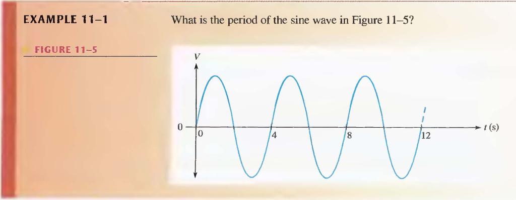
10 Period of a Sine Wave A sine wave varies with time (t) in a definable manner. The time required for a sine wave to complete one full cycle is called the period (T).
11

12 T = 12 / 5 = 2.4s
13 Three Ways to measure the period of a sine wave Method 1: The period can be measured from one zero crossing to the corresponding zero crossing in the next cycle (the slope must be the same at the corresponding zero crossings). Method 2: The period can be measured from the positive peak in one cycle to the positive peak in the next cycle. Method 3: The period can be measured from the negative peak in one cycle to the negative peak in the next cycle.
14 Frequency of a Sine Wave Frequency (f) is the number of cycles that a sine wave completes in one second. The more cycles completed in one second, the higher the frequency. Frequency (f) is measured in units of hertz. One hertz (Hz) is equivalent to one cycle per second; 60 Hz is 60 cycles per second.
15 Relationship of Frequency and Period The formulas for the relationship between frequency (f) and period (T) are as follows: There is a reciprocal relationship between f and T. Knowing one, you can calculate the other with the x -1 or 1/x key on your calculator.
16 AC Generation Sinusoidal Generation voltage of a sine sources wave Sinusoidal voltages are produced by ac generators and electronic oscillators. When a conductor rotates in a constant magnetic field, a sinusoidal wave is generated. N B C A D S A B C D Motion of conductor Conductor When When the the loop conductor is moving is moving perpendicular parallel with to the lines the of lines flux, of the flux, maximum no voltage voltage is induced. is induced.
17 AC generator (alternator) Generators convert rotational energy to electrical energy. A stationary field alternator with a rotating armature is shown. The armature has an induced voltage, which is connected through slip rings and brushes to a load. The armature loops are wound on a magnetic core (not shown for simplicity). Small alternators may use a permanent magnet as shown here; other use field coils to produce the magnetic flux. brushes N armature S slip rings
18 AC generator (alternator) By increasing the number of poles, the number of cycles per revolution is increased. A four-pole generator will produce two complete cycles in each revolution.
19 11-3 SINUSOIDAL VOLTAGE AND CURRENT VALUES Five ways to express the value of a sine wave in terms of its voltage or its current magnitude are instantaneous, peak, peakto-peak, rms, and average values.
20 Instantaneous Value Figure illustrates that at any point in time on a sine wave, the voltage (or current) has an instantaneous value. This instantaneous value is different at different points along the curve. Instantaneous values are positive during the positive alternation and negative during the negative alternation. Instantaneous values of voltage and current are symbolized by lowercase v and i, respectively.
21 The curve in part (a) shows voltage only, but it applies equally for current when the v's are replaced with i's. An example of instantaneous values is shown in part (b).
 with respect to zero.")
22 Peak Value The peak value of a sine wave is the value of voltage (or current) at the positive or the negative maximum (peak) with respect to zero. The peak value is represented by V p or I p.

23 Peak-to-Peak Value The peak-to-peak value of a sine wave, as shown in Figure II-I7, is the voltage or current from the positive peak to the negative peak. It is always twice the peak value. Peak-to-peak voltage or current values are represented by V pp or I pp.
24 RMS Value The term rms stands for root mean square. Most ac voltmeters display rms voltage. The 240 volts at your wall outlet is an rms value. The rms value, also referred to as the effective value, of a sinusoidal voltage is actually a measure of the heating effect of the sine wave.
25 For example, when a resistor is connected across an ac (sinusoidal) voltage source, a certain amount of heat is generated by the power in the resistor. The rms value of a sinusoidal voltage is equal to the dc voltage that produces the same amount of heat in a resistance as does the sinusoidal voltage. The peak value of a sine wave can be converted to the corresponding rms value using the following relationships, derived in Appendix B, for either voltage or current:
26 Using these formulas, you can also determine the peak value if you know the rms value.
27 Average Value The average value of a sine wave taken over one complete cycle is always zero because the positive values (above the zero crossing) offset the negative values (below the zero crossing). To be useful for certain purposes such as measuring types of voltages found in power supplies, the average value of a sine wave is defined over a half-cycle rather than over a full cycle.
28 The average value is the total area under the half-cycle curve divided by the distance in radians of the curve along the horizontal axis. The result is derived in Appendix B and is expressed in terms of the peak value as follows for both voltage and current sine waves:
29 ANGULAR MEASUREMENT OF A SINE WAVE As you have seen, sine waves can be measured along the horizontal axis on a time basis; however, since the time for completion of one full cycle or any portion of a cycle is frequency-dependent, it is often useful to specify points on the sine wave in terms of an angular measurement expressed in degrees or radians.
30 Angular Measurement A degree is an angular measurement corresponding to 1/360 of a circle or a complete revolution. A radian is the angular measurement along the circumference of a circle that is equal to the radius of the circle. In one 360º revolution there are 2π radians. One radian (rad) is equivalent to 57.3
31 Sine Wave Angles The angular measurement of a sine wave is based on 360 or 2π rad for a complete cycle. A half-cycle is 180 or π rad; a quarter-cycle is 90 or 2/π rad; and so on. Figures below show angles in degrees for a full cycle of a sine wave; part (b) shows the same points in radians.
32 Phase of a Sine Wave The phase of a sine wave is an angular measurement that specifies the position of that sine wave relative to a reference. Figure shows one cycle of a sine wave to be used as the reference. Note that the first positive-going crossing of the horizontal axis (zero crossing) is at 0 (0 rad), and the positive peak is at 90 (π/2 rad). The negative-going zero crossing is at 180 (π rad), and the negative peak is at 270 (3π/2 rad). The cycle is completed at 360 (2π rad). When the sine wave is shifted left or right with respect to this reference, there is a phase shift.
33 In part (b), sine wave B is shown shifted left by 90 with respect to sine wave A. Thus, again there is a phase angle of 90 between sine wave A and sine wave B. In this case, the positive peak of sine wave B occurs earlier in time than that of sine wave A. Sine wave B is said to lead sine wave A by 90. In part (a), sine wave B is shifted to the right by 90 with respect to sine wave A. Thus, there is a phase angle of 90 between sine wave A and sine wave B. In this case, sine wave B is said to lag sine wave A by 90
34 The Sine Wave Formula A sine wave can be graphically represented by voltage or current values on the vertical axis and by angular measurement (degrees or radians) along the horizontal axis. This graph can be expressed mathematically, as you will see.
35 A generalized graph of one cycle of a sine wave is shown in Figure The sine wave amplitude (A) is the maximum value of the voltage or current on the vertical axis; angular values run along the horizontal axis. The variable y is an instantaneous value that represents either voltage or current at a given angle, θ. The symbol θ is the Greek letter theta.
36 Sine wave equation Instantaneous values of a wave are shown as v or i. The equation for the instantaneous voltage (v) of a sine wave is where V p = θ = v = V p sinθ Peak voltage Angle in rad or degrees If the peak voltage is 25 V, the instantaneous voltage at 50 degrees is 19.2 V
37 Sine wave equation A plot of the example in the previous slide (peak at 25 V) is shown. The instantaneous voltage at 50 o is 19.2 V as previously calculated. 90 V p v = V p sin = 19.2 V V p = 25 V = V p
38 Expressions for Phase-Shifted Sine Waves When a sine wave is shifted to the right of the reference (lagging) by a certain angle, Φ (Greek letter phi), as illustrated in Figure 11-30(a) where the reference is the vertical axis, the general expression is y = A sin(θ - Φ) where y represents instantaneous voltage or current, and A represents the peak value (amplitude).
39 When a sine wave is shifted to the left of the reference (leading) by a certain angle, Φ, as shown in Figure 11-30(b), the general expression is y = A sin(θ + Φ)
40 Voltage (V) Phase shift Re fe re nc e Example of a wave that lags the reference and the equation has a negative phase shift Peak voltage v = 30 V sin (θ 45 o ) Notice that a lagging sine wave is below the axis at 0 o Angle ( )
41 Voltage (V) Phase shift Re fe re nc e Example of a wave that leads the reference Notice that a leading sine wave is above the axis at 0 o Peak voltage v = 30 V sin (θ + 45 o ) and the equation has a positive phase shift Angle ( )
42 Phasors Phasors provide a graphic means for representing quantities that have both magnitude and direction (angular position). Phasors are especially useful for representing sine waves in terms of their magnitude and phase angle and also for analysis of reactive circuits discussed in later chapters.
43 You may already be familiar with vectors. In math and science, a vector is any quantity with both magnitude and direction. Examples of vectors are force, velocity, and acceleration. The simplest way to describe a vector is to assign a magnitude and an angle to a quantity. In electronics, a phasor is a type of vector but the term generally refers to quantities that vary with time, such as sine waves.
44 Examples of phasors are shown in Figure The length of the phasor "arrow" represents the magnitude of a quantity. The angle, θ (relative to 0 ), represents the angular position, as shown in part (a) for a positive angle. The specific phasor example in part (b) has a magnitude of 2 and a phase angle of 45.
45 The phasor in part (c) has a magnitude of 3 and a phase angle of 180. The phasor in part (d) has a magnitude of I and a phase angle of -45 (or +315 ). Notice that positive angles are measured counterclockwise (CCW) from the reference (0 ) and negative angles are measured clockwise (CW) from the reference.
46 Phasor Representation of a Sine Wave A full cycle of a sine wave can be represented by rotation of a phasor through 360 degrees. The instantaneous value of the sine wave at any point is equal to the vertical distance from the tip of the phasor to the horizontal axis. Figure shows how the phasor traces out the sine wave as it goes from 0 to 360.
47 You can relate this concept to the rotation in an ac generator. Notice that the length of the phasor is equal to the peak value of the sine wave (observe the 90 and the 270 points). The angle of the phasor measured from 0 is the corresponding angular point on the sine wave.
48 Phasors and the Sine Wave Formula Let's examine a phasor representation at one specific angle. Figure shows a voltage phasor at an angular position of 45 and the corresponding point on the sine wave. The instantaneous value of the sine wave at this point is related to both the position and the length of the phasor.
49 As previously mentioned, the vertical distance from the phasor tip down to the horizontal axis represents the instantaneous value of the sine wave at that point. Notice that when a vertical line is drawn from the phasor tip down to the horizontal axis, a right angle triangle is formed. The length of the phasor is the hypotenuse of the triangle, and the vertical projection is the opposite side. From trigonometry, The opposite side of a right triangle is equal to the hypotenuse times the sine of the angle θ.
50 The length of the phasor is the peak value of the sinusoidal voltage, V p. Thus, the opposite side of the triangle, which is the instantaneous value, can be expressed as v = V p sin θ Recall that this formula is the one stated earlier for calculating instantaneous sinusoidal voltage. A similar formula applies to a sinusoidal current. i = I p sinθ
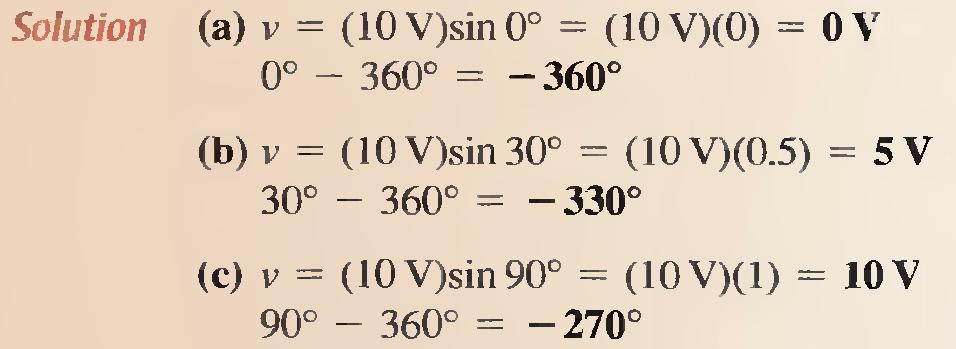
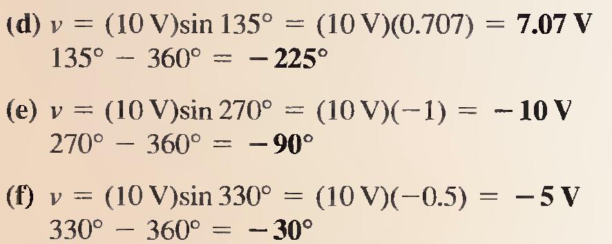
51 Positive and Negative Phasor Angles The position of a phasor at any instant can be expressed as a positive angle, as you have seen, or as an equivalent negative angle. Positive angles are measured counterclockwise from 0. Negative angles are measured clockwise from 0. For a given positive angle θ, the corresponding negative angle is θ - 360, as illustrated in Figure 11-35(a). In part (b), a specific example is shown. The angle of the phasor in this case can be expressed as or -135.
52
53 For the phasor in each part of Figure 11-36, determine the instantaneous voltage value. Also express each positive angle shown as an equivalent negative angle. The length of each phasor represents the peak value of the sinusoidal voltage.
54
55
56 Related Problem: If a phasor is at 45º and its length represents 15V, what is the instantaneous sine wave value?
57 Phasor Diagrams A phasor diagram can be used to show the relative relationship of two or more sine waves of the same frequency. A phasor in a fixed position is used to represent a complete sine wave because once the phase angle between two or more sine waves of the same frequency or between the sine wave and a reference is established, the phase angle remains constant throughout the cycles.
58 For example, the two sine waves in Figure 11-37(a) can be represented by a phasor diagram, as shown in part (b). As you can see, sine wave B leads sine wave A by 30 and has less amplitude than sine wave A, as indicated by the lengths of the phasors.
59 Example of a phasor diagram representing sinusoidal waveforms.
60 Chapter 15
61 Complex Numbers Complex numbers allow mathematical operations with phasor quantities and are useful in the analysis of ac circuits. With the complex number system, you can add, subtract, multiply, and divide quantities that have both magnitude and angle, such as sine waves and other ac circuit quantities.
62 Positive and Negative Numbers Positive numbers are represented by points to the right of the origin on the horizontal axis of a graph, and negative numbers are represented by points to the left of the origin.
63 Also, positive numbers are represented by points on the vertical axis above the origin, and negative numbers are represented by points below the origin.
64 The Complex Plane To distinguish between values on the horizontal axis and values on the vertical axis, a complex plane is used. In the complex plane, the horizontal axis is called the real axis, and the vertical axis is called the imaginary axis. In electrical circuit work, a ±j prefix is used to designate numbers that lie on the imaginary axis in order to distinguish them from numbers lying on the real axis. This prefix is known as the j operator.
65 In mathematics, an i is used instead of a j, but in electric circuits, the i can be confused with instantaneous current, so j is used.
66 Angular Position on the Complex Plane Angular positions are represented on the complex plane. The positive real axis represents zero degrees. Proceeding counterclockwise, the +j axis represents 90º, the negative real axis represents 180º, the -j axis is the 270º point, and, after a full rotation of 360º, you are back to the positive real axis. Notice that the plane is divided into four quadrants.
67
68 Representing a Point on the Complex Plane A point located on the complex plane is classified as real, imaginary (±j), or a combination of the two. For example, a point located 4 units from the origin on the positive real axis is the positive real number, +4. A point 2 units from the origin on the negative real axis is the negative real number, -2.
69 A point on the +j axis 6 units from the origin, as shown in part (c), is the positive imaginary number, +j6. A point 5 units along the -j axis is the negative imaginary number, -j5
70 When a point lies not on any axis but somewhere in one of the four quadrants, it is a complex number and is defined by its coordinates. For example, the point located in the first quadrant has a real value of +4 and a j value of +j4 and is expressed as +4, + j4.
71 The point located in the second quadrant has coordinates - 3 and + j2. The point located in the third quadrant has coordinates -3 and -j5. The point located in the fourth quadrant has coordinates of +6 and -j4.
72 Rectangular and Polar Forms Rectangular and polar are two forms of complex numbers that are used to represent phasor quantities. Each has certain advantages when used in circuit analysis, depending on the particular application. A phasor quantity contains both magnitude and angular position or phase. In this text, italic letters such as V and I are used to represent magnitude only, and boldfaced nonitalic letters such as V and I are used to represent complete phasor quantities.
73 Rectangular Form A phasor quantity is represented in rectangular form by the algebraic sum of the real value (A) of the coordinate and the j value (B) of the coordinate, expressed in the following general form: A ± jb
74 1 st quadrant = 4+j4 2 nd =-3+j2 3 rd =-3-j5 4 th = +6-j4
75 Polar Form Phasor quantities can also be expressed in polar form, which consists of the phasor magnitude (C) and the angular position relative to the positive real axis (θ), expressed in the following general form: C ± θ
76 Examples
77 Conversion from Rectangular to Polar Form The first step to convert from rectangular to polar form is to determine the magnitude of the phasor. A phasor can be visualized as forming a right angle triangle in the complex plane.
78
79 Conversion from Rectangular to Polar Form Basic trig functions, as well as the Pythagorean theorem allow you to convert between rectangular and polar notation and vice-versa. Reviewing these relationships: sinθ = cosθ = opposite side hypotenuse adjacent side hypotenuse Hypotenuse tanθ = opposite side adjacent side Adjac ent side hypotenuse = adjacent side + opposite side
80 Conversion from Rectangular to Polar Form Converting from rectangular form (A + jb), to polar form ( C ± θ) is done as follows: and 2 2 C = A + B θ = tan 1 ± B A +jb C = θ A 2 + B 2 B The method for the first quadrant is illustrated here. A
81 Conversion from Polar to Rectangular Form Converting from polar form ( C ± θ ) to rectangular form (A + jb), ) is done as follows: and A= Ccosθ B = Csinθ Convert to rectangular form j8.46 θ = 45 o C = 12 C B = C sin θ θ A = C cos θ
Circuit Analysis-II. Circuit Analysis-II Lecture # 2 Wednesday 28 th Mar, 18
 Circuit Analysis-II Angular Measurement Angular Measurement of a Sine Wave ü As we already know that a sinusoidal voltage can be produced by an ac generator. ü As the windings on the rotor of the ac generator
Bakiss Hiyana binti Abu Bakar JKE, POLISAS BHAB
 1 Bakiss Hiyana binti Abu Bakar JKE, POLISAS 1. Explain AC circuit concept and their analysis using AC circuit law. 2. Apply the knowledge of AC circuit in solving problem related to AC electrical circuit.
Phasor. Phasor Diagram of a Sinusoidal Waveform
 Phasor A phasor is a vector that has an arrow head at one end which signifies partly the maximum value of the vector quantity ( V or I ) and partly the end of the vector that rotates. Generally, vectors
Ac fundamentals and AC CIRCUITS. Q1. Explain and derive an expression for generation of AC quantity.
 Ac fundamentals and AC CIRCUITS Q1. Explain and derive an expression for generation of AC quantity. According to Faradays law of electromagnetic induction when a conductor is moving within a magnetic field,
CHAPTER 14 ALTERNATING VOLTAGES AND CURRENTS
 CHAPTER 4 ALTERNATING VOLTAGES AND CURRENTS Exercise 77, Page 28. Determine the periodic time for the following frequencies: (a) 2.5 Hz (b) 00 Hz (c) 40 khz (a) Periodic time, T = = 0.4 s f 2.5 (b) Periodic
CHAPTER 5 CONCEPTS OF ALTERNATING CURRENT
 CHAPTER 5 CONCEPTS OF ALTERNATING CURRENT INTRODUCTION Thus far this text has dealt with direct current (DC); that is, current that does not change direction. However, a coil rotating in a magnetic field
Algebra 2/Trigonometry Review Sessions 1 & 2: Trigonometry Mega-Session. The Unit Circle
 Algebra /Trigonometry Review Sessions 1 & : Trigonometry Mega-Session Trigonometry (Definition) - The branch of mathematics that deals with the relationships between the sides and the angles of triangles
AC Sources and Phasors
 AC Sources and Phasors Circuits powered by a sinusoidal emf are called AC circuits, where AC stands for alternating current. Steady-current circuits are called DC circuits, for direct current. The instantaneous
Chapter 33. Alternating Current Circuits
 Chapter 33 Alternating Current Circuits Alternating Current Circuits Electrical appliances in the house use alternating current (AC) circuits. If an AC source applies an alternating voltage to a series
Introduction to Trigonometry. Algebra 2
 Introduction to Trigonometry Algebra 2 Angle Rotation Angle formed by the starting and ending positions of a ray that rotates about its endpoint Use θ to represent the angle measure Greek letter theta
Alternating voltages and currents
 Alternating voltages and currents Introduction - Electricity is produced by generators at power stations and then distributed by a vast network of transmission lines (called the National Grid system) to
Chapter 33. Alternating Current Circuits
 Chapter 33 Alternating Current Circuits C HAP T E O UTLI N E 33 1 AC Sources 33 2 esistors in an AC Circuit 33 3 Inductors in an AC Circuit 33 4 Capacitors in an AC Circuit 33 5 The L Series Circuit 33
Chapter 3, Part 1: Intro to the Trigonometric Functions
 Haberman MTH 11 Section I: The Trigonometric Functions Chapter 3, Part 1: Intro to the Trigonometric Functions In Example 4 in Section I: Chapter, we observed that a circle rotating about its center (i.e.,
10.3 Polar Coordinates
 .3 Polar Coordinates Plot the points whose polar coordinates are given. Then find two other pairs of polar coordinates of this point, one with r > and one with r
Alternating current circuits- Series RLC circuits
 FISI30 Física Universitaria II Professor J.. ersosimo hapter 8 Alternating current circuits- Series circuits 8- Introduction A loop rotated in a magnetic field produces a sinusoidal voltage and current.
2.0 AC CIRCUITS 2.1 AC VOLTAGE AND CURRENT CALCULATIONS. ECE 4501 Power Systems Laboratory Manual Rev OBJECTIVE
 2.0 AC CIRCUITS 2.1 AC VOLTAGE AND CURRENT CALCULATIONS 2.1.1 OBJECTIVE To study sinusoidal voltages and currents in order to understand frequency, period, effective value, instantaneous power and average
Chapter 1. Trigonometry Week 6 pp
 Fall, Triginometry 5-, Week -7 Chapter. Trigonometry Week pp.-8 What is the TRIGONOMETRY o TrigonometryAngle+ Three sides + triangle + circle. Trigonometry: Measurement of Triangles (derived form Greek
Unit 5. Algebra 2. Name:
 Unit 5 Algebra 2 Name: 12.1 Day 1: Trigonometric Functions in Right Triangles Vocabulary, Main Topics, and Questions Definitions, Diagrams and Examples Theta Opposite Side of an Angle Adjacent Side of
ELECTROMAGNETIC INDUCTION AND ALTERNATING CURRENT (Assignment)
") ELECTROMAGNETIC INDUCTION AND ALTERNATING CURRENT (Assignment) 1. In an A.C. circuit A ; the current leads the voltage by 30 0 and in circuit B, the current lags behind the voltage by 30 0. What is the
ELECTROMAGNETIC INDUCTION AND ALTERNATING CURRENT (Assignment) 1. In an A.C. circuit A ; the current leads the voltage by 30 0 and in circuit B, the current lags behind the voltage by 30 0. What is the
Lecture 3 Complex Exponential Signals
 Lecture 3 Complex Exponential Signals Fundamentals of Digital Signal Processing Spring, 2012 Wei-Ta Chu 2012/3/1 1 Review of Complex Numbers Using Euler s famous formula for the complex exponential The
Alternating Current. Slide 1 / 69. Slide 2 / 69. Slide 3 / 69. Topics to be covered. Sources of Alternating EMF. Sources of alternating EMF
 Slide 1 / 69 lternating urrent Sources of alternating EMF Transformers ircuits and Impedance Topics to be covered Slide 2 / 69 LR Series ircuits Resonance in ircuit Oscillations Sources of lternating EMF
Alternating Current. Slide 2 / 69. Slide 1 / 69. Slide 3 / 69. Slide 4 / 69. Slide 6 / 69. Slide 5 / 69. Topics to be covered
 Slide 1 / 69 lternating urrent Sources of alternating EMF ircuits and Impedance Slide 2 / 69 Topics to be covered LR Series ircuits Resonance in ircuit Oscillations Slide 3 / 69 Sources of lternating EMF
ECE 2006 University of Minnesota Duluth Lab 11. AC Circuits
 1. Objective AC Circuits In this lab, the student will study sinusoidal voltages and currents in order to understand frequency, period, effective value, instantaneous power and average power. Also, the
of the whole circumference.
 TRIGONOMETRY WEEK 13 ARC LENGTH AND AREAS OF SECTORS If the complete circumference of a circle can be calculated using C = 2πr then the length of an arc, (a portion of the circumference) can be found by
Chapter 6: Periodic Functions
 Chapter 6: Periodic Functions In the previous chapter, the trigonometric functions were introduced as ratios of sides of a triangle, and related to points on a circle. We noticed how the x and y values
CHAPTER 2. Basic Concepts, Three-Phase Review, and Per Unit
 CHAPTER 2 Basic Concepts, Three-Phase Review, and Per Unit 1 AC power versus DC power DC system: - Power delivered to the load does not fluctuate. - If the transmission line is long power is lost in the
Electrical Theory. Power Principles and Phase Angle. PJM State & Member Training Dept. PJM /22/2018
 Electrical Theory Power Principles and Phase Angle PJM State & Member Training Dept. PJM 2018 Objectives At the end of this presentation the learner will be able to: Identify the characteristics of Sine
MULTIPLE CHOICE. Choose the one alternative that best completes the statement or answers the question.
 Trigonometry Final Exam Study Guide Name MULTIPLE CHOICE. Choose the one alternative that best completes the statement or answers the question. The graph of a polar equation is given. Select the polar
Trigonometry. An Overview of Important Topics
 Trigonometry An Overview of Important Topics 1 Contents Trigonometry An Overview of Important Topics... 4 UNDERSTAND HOW ANGLES ARE MEASURED... 6 Degrees... 7 Radians... 7 Unit Circle... 9 Practice Problems...
Unit Circle: Sine and Cosine
 Unit Circle: Sine and Cosine Functions By: OpenStaxCollege The Singapore Flyer is the world s tallest Ferris wheel. (credit: Vibin JK /Flickr) Looking for a thrill? Then consider a ride on the Singapore
Alternating Current Page 1 30
 Alternating Current 26201 11 Page 1 30 Calculate the peak and effective voltage of current values for AC Calculate the phase relationship between two AC waveforms Describe the voltage and current phase
CHAPTER 9. Sinusoidal Steady-State Analysis
 CHAPTER 9 Sinusoidal Steady-State Analysis 9.1 The Sinusoidal Source A sinusoidal voltage source (independent or dependent) produces a voltage that varies sinusoidally with time. A sinusoidal current source
AC phase. Resources and methods for learning about these subjects (list a few here, in preparation for your research):
:") AC phase This worksheet and all related files are licensed under the Creative Commons Attribution License, version 1.0. To view a copy of this license, visit http://creativecommons.org/licenses/by/1.0/,
AC phase This worksheet and all related files are licensed under the Creative Commons Attribution License, version 1.0. To view a copy of this license, visit http://creativecommons.org/licenses/by/1.0/,
Chapter 6: Periodic Functions
 Chapter 6: Periodic Functions In the previous chapter, the trigonometric functions were introduced as ratios of sides of a right triangle, and related to points on a circle. We noticed how the x and y
Module 1. Introduction. Version 2 EE IIT, Kharagpur
 Module 1 Introduction Lesson 1 Introducing the Course on Basic Electrical Contents 1 Introducing the course (Lesson-1) 4 Introduction... 4 Module-1 Introduction... 4 Module-2 D.C. circuits.. 4 Module-3
Triangle Definition of sin θ and cos θ
 Triangle Definition of sin θ and cos θ Then Consider the triangle ABC below. Let A be called θ. A HYP (hpotenuse) θ ADJ (side adjacent to the angle θ ) B C OPP (side opposite to the angle θ ) (SOH CAH
1. Measure angle in degrees and radians 2. Find coterminal angles 3. Determine the arc length of a circle
 Pre- Calculus Mathematics 12 5.1 Trigonometric Functions Goal: 1. Measure angle in degrees and radians 2. Find coterminal angles 3. Determine the arc length of a circle Measuring Angles: Angles in Standard
Mod E - Trigonometry. Wednesday, July 27, M132-Blank NotesMOM Page 1
 M132-Blank NotesMOM Page 1 Mod E - Trigonometry Wednesday, July 27, 2016 12:13 PM E.0. Circles E.1. Angles E.2. Right Triangle Trigonometry E.3. Points on Circles Using Sine and Cosine E.4. The Other Trigonometric
Physics 132 Quiz # 23
 Name (please (please print) print) Physics 132 Quiz # 23 I. I. The The current in in an an ac ac circuit is is represented by by a phasor.the value of of the the current at at some time time t t is is
Math 102 Key Ideas. 1 Chapter 1: Triangle Trigonometry. 1. Consider the following right triangle: c b
 Math 10 Key Ideas 1 Chapter 1: Triangle Trigonometry 1. Consider the following right triangle: A c b B θ C a sin θ = b length of side opposite angle θ = c length of hypotenuse cosθ = a length of side adjacent
7.1 INTRODUCTION TO PERIODIC FUNCTIONS
 7.1 INTRODUCTION TO PERIODIC FUNCTIONS *SECTION: 6.1 DCP List: periodic functions period midline amplitude Pg 247- LECTURE EXAMPLES: Ferris wheel, 14,16,20, eplain 23, 28, 32 *SECTION: 6.2 DCP List: unit
Chapter 11. Alternating Current
 Unit-2 ECE131 BEEE Chapter 11 Alternating Current Objectives After completing this chapter, you will be able to: Describe how an AC voltage is produced with an AC generator (alternator) Define alternation,
Name: A Trigonometric Review June 2012
 Name: A Trigonometric Review June 202 This homework will prepare you for in-class work tomorrow on describing oscillations. If you need help, there are several resources: tutoring on the third floor of
Chapter 6: Alternating Current. An alternating current is an current that reverses its direction at regular intervals.
 Chapter 6: Alternating Current An alternating current is an current that reverses its direction at regular intervals. Overview Alternating Current Phasor Diagram Sinusoidal Waveform A.C. Through a Resistor
10. Introduction and Chapter Objectives
 Real Analog - Circuits Chapter 0: Steady-state Sinusoidal Analysis 0. Introduction and Chapter Objectives We will now study dynamic systems which are subjected to sinusoidal forcing functions. Previously,
Chapter 6: Periodic Functions
 Chapter 6: Periodic Functions In the previous chapter, the trigonometric functions were introduced as ratios of sides of a triangle, and related to points on a circle. We noticed how the x and y values
Unit 8 Trigonometry. Math III Mrs. Valentine
 Unit 8 Trigonometry Math III Mrs. Valentine 8A.1 Angles and Periodic Data * Identifying Cycles and Periods * A periodic function is a function that repeats a pattern of y- values (outputs) at regular intervals.
Figure 1. The unit circle.
 TRIGONOMETRY PRIMER This document will introduce (or reintroduce) the concept of trigonometric functions. These functions (and their derivatives) are related to properties of the circle and have many interesting
PREREQUISITE/PRE-CALCULUS REVIEW
 PREREQUISITE/PRE-CALCULUS REVIEW Introduction This review sheet is a summary of most of the main topics that you should already be familiar with from your pre-calculus and trigonometry course(s), and which
Table of Contents. Introduction...2 Conductors and Insulators...3 Current, Voltage, and Resistance...6
 Table of Contents Introduction...2 Conductors and Insulators...3 Current, Voltage, and Resistance...6 Ohm s Law... 11 DC Circuits... 13 Magnetism...20 Alternating Current...23 Inductance and Capacitance...30
AC Circuit Analysis. The Sine Wave CHAPTER 3. This chapter discusses basic concepts in the analysis of AC circuits.
 CHAPTER 3 AC Circuit Analysis This chapter discusses basic concepts in the analysis of AC circuits. The Sine Wave AC circuit analysis usually begins with the mathematical expression for a sine wave: v(t)
Experiment 1 Alternating Current with Coil and Ohmic Resistors
 Experiment Alternating Current with Coil and Ohmic esistors - Objects of the experiment - Determining the total impedance and the phase shift in a series connection of a coil and a resistor. - Determining
PHYSICS WORKSHEET CLASS : XII. Topic: Alternating current
 PHYSICS WORKSHEET CLASS : XII Topic: Alternating current 1. What is mean by root mean square value of alternating current? 2. Distinguish between the terms effective value and peak value of an alternating
CIRCLE DIAGRAMS. Learning Objectives. Combinations of R and C circuits
 H A P T E R18 earning Objectives ircle Diagram of a Series ircuit Rigorous Mathematical Treatment onstant Resistance but ariable Reactance Properties of onstant Reactance But ariable Resistance ircuit
7.1 INTRODUCTION TO PERIODIC FUNCTIONS
 7.1 INTRODUCTION TO PERIODIC FUNCTIONS Ferris Wheel Height As a Function of Time The London Eye Ferris Wheel measures 450 feet in diameter and turns continuously, completing a single rotation once every
6.1 - Introduction to Periodic Functions
 6.1 - Introduction to Periodic Functions Periodic Functions: Period, Midline, and Amplitude In general: A function f is periodic if its values repeat at regular intervals. Graphically, this means that
AC Fundamental. Simple Loop Generator: Whenever a conductor moves in a magnetic field, an emf is induced in it.
 AC Fundamental Simple Loop Generator: Whenever a conductor moves in a magnetic field, an emf is induced in it. Fig.: Simple Loop Generator The amount of EMF induced into a coil cutting the magnetic lines
Math 1205 Trigonometry Review
 Math 105 Trigonometry Review We begin with the unit circle. The definition of a unit circle is: x + y =1 where the center is (0, 0) and the radius is 1. An angle of 1 radian is an angle at the center of
Chapter 6: Alternating Current
 hapter 6: Alternating urrent 6. Alternating urrent.o 6.. Define alternating current (A) An alternating current (A) is the electrical current which varies periodically with time in direction and magnitude.
AC generator theory. Resources and methods for learning about these subjects (list a few here, in preparation for your research):
:") AC generator theory This worksheet and all related files are licensed under the Creative Commons Attribution License, version 1.0. To view a copy of this license, visit http://creativecommons.org/licenses/by/1.0/,
AC generator theory This worksheet and all related files are licensed under the Creative Commons Attribution License, version 1.0. To view a copy of this license, visit http://creativecommons.org/licenses/by/1.0/,
Double-Angle, Half-Angle, and Reduction Formulas
 Double-Angle, Half-Angle, and Reduction Formulas By: OpenStaxCollege Bicycle ramps for advanced riders have a steeper incline than those designed for novices. Bicycle ramps made for competition (see [link])
Trigonometric identities
 Trigonometric identities An identity is an equation that is satisfied by all the values of the variable(s) in the equation. For example, the equation (1 + x) = 1 + x + x is an identity. If you replace
Introduction to signals and systems
 CHAPTER Introduction to signals and systems Welcome to Introduction to Signals and Systems. This text will focus on the properties of signals and systems, and the relationship between the inputs and outputs
Modular Electronics Learning (ModEL) project
 project") Modular Electronics Learning (ModEL) project V = I R * SPICE ckt v1 1 0 dc 12 v2 2 1 dc 15 r1 2 3 4700 r2 3 0 7100.dc v1 12 12 1.print dc v(2,3).print dc i(v2).end Phasor Mathematics c 2017 by Tony R.
Modular Electronics Learning (ModEL) project V = I R * SPICE ckt v1 1 0 dc 12 v2 2 1 dc 15 r1 2 3 4700 r2 3 0 7100.dc v1 12 12 1.print dc v(2,3).print dc i(v2).end Phasor Mathematics c 2017 by Tony R.
AP Physics Electricity and Magnetism #7 Inductance
 Name Period AP Physics Electricity and Magnetism #7 Inductance Dr. Campbell 1. Do problems Exercise B page 589 and problem 2, 3, 8, 9 page 610-1. Answers at the end of the packet. 2. A 20-turn wire coil
AC Theory, Circuits, Generators & Motors
 PDH-Pro.com AC Theory, Circuits, Generators & Motors Course Number: EE-02-306 PDH: 6 Approved for: AK, AL, AR, GA, IA, IL, IN, KS, KY, MD, ME, MI, MN, MO, MS, MT, NC, ND, NE, NH, NJ, NM, NV, OH, OK, OR,
Precalculus Lesson 9.2 Graphs of Polar Equations Mrs. Snow, Instructor
 Precalculus Lesson 9.2 Graphs of Polar Equations Mrs. Snow, Instructor As we studied last section points may be described in polar form or rectangular form. Likewise an equation may be written using either
2. (8pts) If θ is an acute angle, find the values of all the trigonometric functions of θ given
 If θ is an acute angle, find the values of all the trigonometric functions of θ given") Trigonometry Joysheet 1 MAT 145, Spring 2017 D. Ivanšić Name: Covers: 6.1, 6.2 Show all your work! 1. 8pts) If θ is an acute angle, find the values of all the trigonometric functions of θ given that sin
Trigonometry Joysheet 1 MAT 145, Spring 2017 D. Ivanšić Name: Covers: 6.1, 6.2 Show all your work! 1. 8pts) If θ is an acute angle, find the values of all the trigonometric functions of θ given that sin
Section 5.1 Angles and Radian Measure. Ever Feel Like You re Just Going in Circles?
 Section 5.1 Angles and Radian Measure Ever Feel Like You re Just Going in Circles? You re riding on a Ferris wheel and wonder how fast you are traveling. Before you got on the ride, the operator told you
UNIT Explain the radiation from two-wire. Ans: Radiation from Two wire
 UNIT 1 1. Explain the radiation from two-wire. Radiation from Two wire Figure1.1.1 shows a voltage source connected two-wire transmission line which is further connected to an antenna. An electric field
Goals. Introduction. To understand the use of root mean square (rms) voltages and currents.
 voltages and currents.") Lab 10. AC Circuits Goals To show that AC voltages cannot generally be added without accounting for their phase relationships. That is, one must account for how they vary in time with respect to one another.
Lab 10. AC Circuits Goals To show that AC voltages cannot generally be added without accounting for their phase relationships. That is, one must account for how they vary in time with respect to one another.
Understanding Signals with the PropScope Supplement & Errata
 Web Site: www.parallax.com Forums: forums.parallax.com Sales: sales@parallax.com Technical: support@parallax.com Office: (96) 64-8333 Fax: (96) 64-8003 Sales: (888) 5-04 Tech Support: (888) 997-867 Understanding
Analytic Geometry/ Trigonometry
 Analytic Geometry/ Trigonometry Course Numbers 1206330, 1211300 Lake County School Curriculum Map Released 2010-2011 Page 1 of 33 PREFACE Teams of Lake County teachers created the curriculum maps in order
Exercise 9: inductor-resistor-capacitor (LRC) circuits
 circuits") Exercise 9: inductor-resistor-capacitor (LRC) circuits Purpose: to study the relationship of the phase and resonance on capacitor and inductor reactance in a circuit driven by an AC signal. Introduction
Exercise 9: inductor-resistor-capacitor (LRC) circuits Purpose: to study the relationship of the phase and resonance on capacitor and inductor reactance in a circuit driven by an AC signal. Introduction
Electrical Circuits (2)
") Electrical Circuits (2) Lecture 1 Intro. & Review Dr.Eng. Basem ElHalawany Course Info Title Electric Circuits (2) Lecturer: Lecturer Webpage: Teaching Assistant (TA) Course Webpage References Software
Electrical Circuits (2) Lecture 1 Intro. & Review Dr.Eng. Basem ElHalawany Course Info Title Electric Circuits (2) Lecturer: Lecturer Webpage: Teaching Assistant (TA) Course Webpage References Software
Complex Numbers in Electronics
 P5 Computing, Extra Practice After Session 1 Complex Numbers in Electronics You would expect the square root of negative numbers, known as complex numbers, to be only of interest to pure mathematicians.
How to Graph Trigonometric Functions
 How to Graph Trigonometric Functions This handout includes instructions for graphing processes of basic, amplitude shifts, horizontal shifts, and vertical shifts of trigonometric functions. The Unit Circle
Goals. Introduction. To understand the use of root mean square (rms) voltages and currents.
 voltages and currents.") Lab 10. AC Circuits Goals To show that AC voltages cannot generally be added without accounting for their phase relationships. That is, one must account for how they vary in time with respect to one another.
Lab 10. AC Circuits Goals To show that AC voltages cannot generally be added without accounting for their phase relationships. That is, one must account for how they vary in time with respect to one another.
Basic Trigonometry You Should Know (Not only for this class but also for calculus)
") Angle measurement: degrees and radians. Basic Trigonometry You Should Know (Not only for this class but also for calculus) There are 360 degrees in a full circle. If the circle has radius 1, then the circumference
Angle measurement: degrees and radians. Basic Trigonometry You Should Know (Not only for this class but also for calculus) There are 360 degrees in a full circle. If the circle has radius 1, then the circumference
Section 2. AC Circuits
 Section 2 AC Circuits Chapter 12 Alternating Current Objectives After completing this chapter, the student should be able to: Describe how an AC voltage is produced with an AC generator. Define alternation,
2009 A-level Maths Tutor All Rights Reserved
 2 This book is under copyright to A-level Maths Tutor. However, it may be distributed freely provided it is not sold for profit. Contents radians 3 sine, cosine & tangent 7 cosecant, secant & cotangent
Mathematics Lecture. 3 Chapter. 1 Trigonometric Functions. By Dr. Mohammed Ramidh
 Mathematics Lecture. 3 Chapter. 1 Trigonometric Functions By Dr. Mohammed Ramidh Trigonometric Functions This section reviews the basic trigonometric functions. Trigonometric functions are important because
JEFFERSON COLLEGE COURSE SYLLABUS ETC104 AC CIRCUITS. 5 Credit Hours. Prepared by: Ronald S. Krive. Revised Date: October 2007 by Dennis Eimer
 JEFFERSON COLLEGE COURSE SYLLABUS ETC104 AC CIRCUITS 5 Credit Hours Prepared by: Ronald S. Krive Revised Date: October 2007 by Dennis Eimer Division of Technology Dr. John Keck, Dean Ms. Brenda Russell,
Sinusoids and Phasors (Chapter 9 - Lecture #1) Dr. Shahrel A. Suandi Room 2.20, PPKEE
 Dr. Shahrel A. Suandi Room 2.20, PPKEE") Sinusoids and Phasors (Chapter 9 - Lecture #1) Dr. Shahrel A. Suandi Room 2.20, PPKEE Email:shahrel@eng.usm.my 1 Outline of Chapter 9 Introduction Sinusoids Phasors Phasor Relationships for Circuit Elements
Sinusoids and Phasors (Chapter 9 - Lecture #1) Dr. Shahrel A. Suandi Room 2.20, PPKEE Email:shahrel@eng.usm.my 1 Outline of Chapter 9 Introduction Sinusoids Phasors Phasor Relationships for Circuit Elements
15. the power factor of an a.c circuit is.5 what will be the phase difference between voltage and current in this
 1 1. In a series LCR circuit the voltage across inductor, a capacitor and a resistor are 30 V, 30 V and 60 V respectively. What is the phase difference between applied voltage and current in the circuit?
MATH 255 Applied Honors Calculus III Winter Homework 1. Table 1: 11.1:8 t x y
 MATH 255 Applied Honors Calculus III Winter 2 Homework Section., pg. 692: 8, 24, 43. Section.2, pg. 72:, 2 (no graph required), 32, 4. Section.3, pg. 73: 4, 2, 54, 8. Section.4, pg. 79: 6, 35, 46. Solutions.:
Chapter 4 Trigonometric Functions
 Chapter 4 Trigonometric Functions Section 1 Section 2 Section 3 Section 4 Section 5 Section 6 Section 7 Section 8 Radian and Degree Measure Trigonometric Functions: The Unit Circle Right Triangle Trigonometry
AC Theory and Electronics
 AC Theory and Electronics An Alternating Current (AC) or Voltage is one whose amplitude is not constant, but varies with time about some mean position (value). Some examples of AC variation are shown below:
 http://www.math.utah.edu/~palais/sine.html http://www.ies.co.jp/math/java/trig/index.html http://www.analyzemath.com/function/periodic.html http://math.usask.ca/maclean/sincosslider/sincosslider.html http://www.analyzemath.com/unitcircle/unitcircle.html
Alternating Current. Asist. Prof. Dr. Aytaç Gören Asist. Prof. Dr. Levent Çetin
 Asist. Prof. Dr. Aytaç Gören Asist. Prof. Dr. Levent Çetin 30.10.2012 Contents Alternating Voltage Phase Phasor Representation of AC Behaviors of Basic Circuit Components under AC Resistance, Reactance
Section 8.1 Radians and Arc Length
 Section 8. Radians and Arc Length Definition. An angle of radian is defined to be the angle, in the counterclockwise direction, at the center of a unit circle which spans an arc of length. Conversion Factors:
Trigonometric Equations
 Chapter Three Trigonometric Equations Solving Simple Trigonometric Equations Algebraically Solving Complicated Trigonometric Equations Algebraically Graphs of Sine and Cosine Functions Solving Trigonometric
1. If the flux associated with a coil varies at the rate of 1 weber/min,the induced emf is
 1. f the flux associated with a coil varies at the rate of 1 weber/min,the induced emf is 1 1. 1V 2. V 60 3. 60V 4. Zero 2. Lenz s law is the consequence of the law of conservation of 1. Charge 2. Mass
D.3. Angles and Degree Measure. Review of Trigonometric Functions
 APPENDIX D. Review of Trigonometric Functions D7 APPENDIX D. Review of Trigonometric Functions Angles and Degree Measure Radian Measure The Trigonometric Functions Evaluating Trigonometric Functions Solving
Electromagnetic Induction - A
 Electromagnetic Induction - A APPARATUS 1. Two 225-turn coils 2. Table Galvanometer 3. Rheostat 4. Iron and aluminum rods 5. Large circular loop mounted on board 6. AC ammeter 7. Variac 8. Search coil
Trigonometry Review Tutorial Shorter Version
 Author: Michael Migdail-Smith Originally developed: 007 Last updated: June 4, 0 Tutorial Shorter Version Avery Point Academic Center Trigonometric Functions The unit circle. Radians vs. Degrees Computing
An induced emf is the negative of a changing magnetic field. Similarly, a self-induced emf would be found by
 This is a study guide for Exam 4. You are expected to understand and be able to answer mathematical questions on the following topics. Chapter 32 Self-Induction and Induction While a battery creates an
MATH 1113 Exam 3 Review. Fall 2017
 MATH 1113 Exam 3 Review Fall 2017 Topics Covered Section 4.1: Angles and Their Measure Section 4.2: Trigonometric Functions Defined on the Unit Circle Section 4.3: Right Triangle Geometry Section 4.4:
Ferris Wheel Activity. Student Instructions:
 Ferris Wheel Activity Student Instructions: Today we are going to start our unit on trigonometry with a Ferris wheel activity. This Ferris wheel will be used throughout the unit. Be sure to hold on to
13.4 Chapter 13: Trigonometric Ratios and Functions. Section 13.4
 13.4 Chapter 13: Trigonometric Ratios and Functions Section 13.4 1 13.4 Chapter 13: Trigonometric Ratios and Functions Section 13.4 2 Key Concept Section 13.4 3 Key Concept Section 13.4 4 Key Concept Section