Advanced Fibre Testing: Paving the Way for High-Speed Networks. Trevor Nord Application Specialist JDSU (UK) Ltd
|
|
|
- Ruby Antonia Waters
- 6 years ago
- Views:
Transcription
")
1 Advanced Fibre Testing: Paving the Way for High-Speed Networks Trevor Nord Application Specialist JDSU (UK) Ltd
2 Fibre Review Singlemode Optical Fibre
 Bending Losses -")

3 Elements of Loss Fibre Attenuation - Caused by scattering & absorption of light as it travels through the fibre - Measured as function of wavelength (db/km) Bending Losses - Microbending losses are due to microscopic fibre deformations in the core-cladding interface - Macrobending losses are due to physical bends in the fibre that are large in relation to fibre diameter
4 Absorption and Scattering Absorption: Light is absorbed due to chemical properties or natural impurities in the glass. Accounts for about 5% of total loss. O Si Si O O Imperfections Pure Glass=Si O 2 Scattering is the loss of a light signal from the fiber core caused by impurities or changes in the index of refraction of the fiber. Accounts for about 95% of total loss. O Si Si Si O Cu Impurities Light scattered
5 Useful optical phenomena OTDR depends on two types of phenomena: - Rayleigh scattering - Fresnel reflections. Rayleigh scattering and backscattering effect in a fibre Light reflection phenomenon = Fresnel reflection


6 Optical Return Loss (ORL) - The ORL is the amount of transmitted light reflected back to the source - The ORL is measured in db and is a positive value. - The higher the number, the smaller the reflection. Examples: +50dB is a good value +17dB is a bad value!! - Increase transmitter noise Reducing the OSNR in analog video transmission Increasing the BER in digital transmission systems - Increase light source interference Changes central wavelength and output power - Higher incidence of transmitter damage SC - PC SC - APC Angled connectors (APC) reduce the back-reflection

7 Chromatic Dispersion In telecom transmission, a pulse of light is composed by multiple wavelengths (colors) which travel at different speed, causing chromatic dispersion Pulse Spreading λ 1 λ 5 λ 4 λ 3 λ 2 Chromatic Dispersion In DWDM transmission, each wavelength travels at a different speed. This can have an impact on number of channels being carried, the channel spacing and the total link length
8 Effect - Transmission Speed and Distance Limitations Input pulses Low Data Rate Output pulses The variation of index according to the wavelength broadens the pulse and causes it to interfere with neighboring pulses Higher Data Rate Digital pulses overlapping CD starts being a problem at 10 Gbit/s especially for G652 fibers and is critical at 40Gbit/s Data Rate Max. Distance for G.652 at 1550nm Max. Distance for G.655 at 1550nm 2.5 Gbit/s 980km 2770km 10 Gbit/s 61km 175km 40 Gbit/s 3.8km 10.8km
9 Fibre Types and Compensation 20 Examples of Chromatic Dispersion values at 1550nm: - G.652 : ~ 17 ps/(nm.km) - G.653 : 0 ps/(nm.km) - G.655 : ~4 ps/(nm.km) λ (nm) As CD is a linear parameter, intrinsic to the fibre, it can be compensated. There are different techniques which enable compensating CD (such as Dispersion Compensating Fibre with negative CD values) Dispersion (ps/nm.km) SMF + DCF λ (nm) 1300 nm 1550 nm DCF Example of a dispersion compensation result on a SMF fiber
10 Chromatic Dispersion Fibre Classification ITU-T Fibre Type description Zero wavelength Dispersion at 1550nm Dispersion G.652 Non Dispersion Shifted fibre nm 17 ps/nm.km ps/nm².km G.653 Dispersion Shifted fibre nm 0 ps/nm.km 0.07 ps/nm².km G.655 Non zero Dispersion Shifted fibre Negative Non zero dispersion shifted fibre Not specified but ~ nm G.656 Broadband NZDSF 8 ps/nm.km 4 ps/nm.km to 0.1 ps/nm².km -5ps/nm.km 0.05 to 0.12 ps/nm².km
11 Polarization Mode Dispersion - Although we refer to fibres as singlemode, in reality the light energy is carried along in different modes known as polarization modes - PMD is caused because the fibre is birefringent (Silica, the base material of optical fibres is birefringent): Two principal polarization modes travel at different speed Slow axis PMD is caused by geometrical irregularities of the fiber - Elliptical and Assymetries Core stress Cladding eccentricity Elliptical fiber design Optical fiber Fast axis PMD depends on mechanical stress - Bends and Twists Fiber twist Fiber stress Fiber bend


12 Birefringent Crystal


13 Effect - Transmission Speed and Distance Limitations V 1 DGD V 1 V 2 V 2 Stress!!! ( bending, twisting) Temperature v 2 DGD Slow Fast v 1
14 Effect - Transmission Speed and Distance Limitations - DGD is a randomly varying quantity. It varies significantly with wavelength and times (changes may be introduced by vibration, movement or changes in temperature ) - DGD varies so much that a parameter has been defined: the PMD coefficient (average value of DGD along a range of conditions) PMD is directly linked to bit interval error ? 1 For a PMD value of 0.5ps/ km, max distance: PMD puts limits on the transmission speed of the networks PMD puts limits on transmission distance of the networks
15 Limiting Fibre Parameters The standards recommend that the maximum admissible PMD delay is 10% of the bit length. SONET Transmission Rate Bit Time PMD Limit STM Mb/s 1600 ps 160 ps STM Gb/s 400 ps 40 ps STM Gb/s 100 ps 10 ps STM Gb/s 25 ps 2.5 ps PMD sensitivity - If the PMD measurement is bad, then the fibre is considered as PMD sensitive. Simple transmission shall apply to this fibre, as no compensation exists so far - If the PMD measurement is good, then the fibre cannot be considered as PMD insensitive or non-pmd sensitive

16 DGD variance over time and wavelength
17 Coping with PMD OFC 2007 survey data showed that about 25% of UK fibre had PMD greater than 0.5ps/ km Testing and record keeping If you do not know the size of the issue, it should be measured Agile Optical Network - Dynamic Channel Allocation If a specific wavelength is suffering because of excessive DGD then it may be possible to move the traffic to a different channel with better DGD performance or even to a different route Polarisation scrambling and FEC Covers all channels Scrambling reduces the impact of the DGD to reduce outages Remaining errors fixed by FEC Optical PMD Compensators Use polarisation controllers with a control/feedback loop
18 Why measure the Spectral Attenuation Profile of a fibre? The purpose of the spectral attenuation (AP) measurement is to represent the attenuation as a function of the wavelength. Historically, this measurement was required mainly for long-haul applications. With the increase of CWDM deployment and the extension of the DWDM wavelength range, it is becoming necessary to have a clear picture of the fiber attenuation other the wavelengths intended to be loaded with traffic.
19 Characterising the full wavelength range In long distance transmissions, as well as at very high bit rate (10G, 40G systems), Raman amplifications are becoming more widely used across the whole spectrum. In addition, distal pumping of Erbium amplifiers at 1480 nm are currently deployed. Characterising fibre at the pump wavelengths (1420, 1450 nm, 1480 nm, etc.) is of high interest to ensure amplification will occur along the required distance.
20 Characterising Fibre Plant Understanding Fibre Link and Network Characterisation
21 What is Fibre Characterisation? Simply the process of testing optical fibres to ensure that they are suitable for the type of transmission (i.e. WDM, SDH, OTN, Ethernet) for which they will be used. The type of transmission will dictate the measurement standards used Transmission type Speed PMD Max CD Max SDH 10 Gbs 10 ps 1176ps/nm Ethernet 10 Gbs 5 ps 738 ps/nm SDH 40 Gbs 2.5 ps 64 ps/nm
22 When should I consider testing? Std CD PMD - New cable Installs (10G+) - Planning / Upgrading existing plant - Following purchase or lease of existing plant - Periodic tests over time - After cable maintenance - Determine if dispersion compensation required
23 Link & Network Characterisation Link Characterisation It measures the fibre performance and the quality of any interconnections The suite of tests mostly depend on the user s methods and procedures It could be uni- or bi-directional Tests Connector Inspection, IL, ORL, OTDR, PMD, CD, AP Network Characterisation It provides the network baseline measurements before turning the transmission system up. Network Characterisation includes measurements through the optical amplifiers, dispersion compensators, and any elements in line. It is a limited suite of tests as compared to Link Characterization ROADM Point A Point B Router DWDM Optical Networ k Optical Amplifier Video Headend Optical Amp. CWDM/DWDM Optical Network


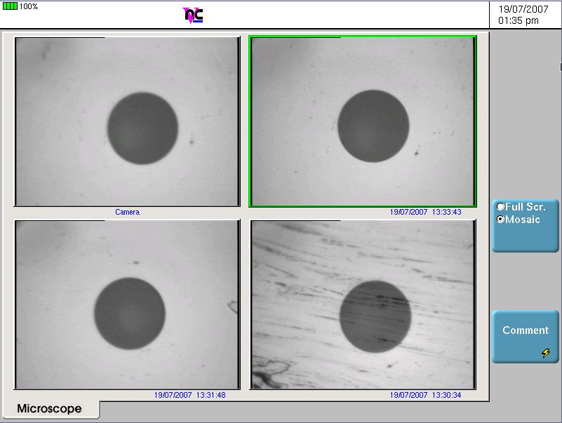
24 Testing the Fibre Charge Connector inspection Insertion Loss Optical Return Loss OTDR Polarization Mode Dispersion Chromatic dispersion Spectral Attenuation


25 Contamination and Signal Performance 1 CLEAN CONNECTION Fibre Contamination and Its Effect on Signal Performance Back Reflection = db Total Loss = db 3 DIRTY CONNECTION Clean Connection vs. Dirty Connection This OTDR trace illustrates a significant decrease in signal performance when dirty connectors are mated. Back Reflection = db Total Loss = 4.87 db
26 d B M e n el u Measuring Insertion Loss (IL) The insertion loss measurement over a complete link requires a calibrated source and a power meter. This is a unidirectional measurement, however could be performed bi-directionally for operation purposes Calibrated Light Source Optical Power Meter d W B m >2s Perm Ca nc dw B d m B P t P r It is the difference between the transmitted power and the received power at each end of the link
27 Measuring Optical Return Loss (ORL) The 2 predominant test methods are available: Optical Continuous Wave Reflectometry (OCWR) An Optical Return Loss Meter (composed of a laser source and a power meter on the same test port) Optical Time Domain Reflectometry (OTDR) The OTDR is able to measure not only the total ORL of the link but also section ORL (cursor A B) OCWR Method OTDR Method
 Typical Application Strengths Weaknesses ± 0.")
28 OCWR vs OTDR Optical Continuous Wave Reflectometer Display Process Controller CW Stabilized Light Source Power Meter Coupler Termination Plug Accuracy (typ.) Typical Application Strengths Weaknesses ± 0.5dB - Total link ORL & isolated event reflectance measurements during fiber installation & commissioning - Accuracy - Fast & real time info - Simple & easy results (direct value) - No localization Optical Time Domain Reflectometer Display Process Controller Pulsed Light Source Photodetector Coupler Accuracy (typ.) Typical Application Strengths Weaknesses ± 2dB - Perfect tool for troubleshooting- Spatial characterization of reflective events & estimation of the partial & total ORL - Locate reflective events - Single-end measurement - Accuracy - Long acquisition time
 Provides physical distance to each event/ impairment Measures fibre attenuation loss of each event or impairment Provides")
29 Measuring Loss, ORL and Distance with an OTDR It s the single most important tester used in the installation, maintenance & troubleshooting of fibre plant Most versatile of Fibre Test Tools Identifies events & impairments (splices, bends, connectors, breaks) Provides physical distance to each event/ impairment Measures fibre attenuation loss of each event or impairment Provides reflectance / return loss values for each reflective event or impairment Manages the data collected and supports data reporting.


30 Bi-Directional OTDR Analysis Bi-directional OTDR Analysis True splice loss measurement (gives the average loss which eliminates for example the effect of fibre mismatch). Reveals events that are hidden by dead zones in one direction.

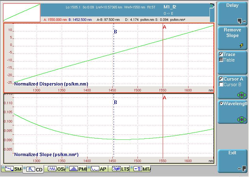
31 Measuring CD Reference test method defined by IEC and ITU-T G650.1 The modulated light is sent over the Fibre Under Test. The phase of the test signal is compared to the phase of the reference signal used to modulate the input signal. The measured value is the group delay corresponding to a wavelength interval. It is calculated using an approximation formula. The chromatic dispersion is then calculated by taking the derivative of the group delay with respect to wavelength. Ref Detection Phase Shift φ Modulated Broadband source λ nm Fibre under test Reference Filter λ ref (1550nm) λ n Wavelength Tunable Charge Phase detection & comparison λ ref λ n Measurement Signal Detection

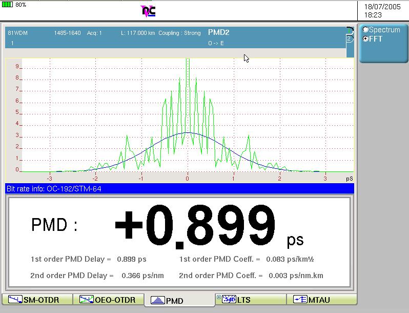
32 Measuring PMD A polarized light is sent over the Fibre Under Test and the transmitted spectrum is analyzed with an Optical Spectrum Analyzer A reference power level is taken without the polarizer in the optical path The scan is then repeated with the polarizer inserted. There will be some fluctuations in the received optical power. The system calculates the ratio of the 2 power levels scans. It s possible to shift to the time domain the analysis of the fixed-analyzer response by taking the Fourier transform of the power fluctuations with wavelength. Broadband Source Polarizer FUT Polarizer Charge

33 Measuring Spectral Attenuation - Shows the spectrum of the fibre (e.g. see if the water peak is present) - Provides the total loss at each wavelength (equivalent to a light source and power meter) Broadband Source Isolator Spectrum Analyzer Reference Broadband Source Isolator FUT Spectrum Analyzer After Fibre Loss Spectrum Comparison Water Peak


34 Fibre Characterisation Results

35
There are lots of problems or challenges with fiber, Attenuation, Reflections, Dispersion and so on. So here we will look at these problems.
 The Hard theory The Hard Theory An introduction to fiber, should also include a section with some of the difficult theory. So if everything else in the book was very easily understood, then this section
Total care for networks. Introduction to Dispersion
 Introduction to Dispersion Introduction to PMD Version1.0- June 01, 2000 Copyright GN Nettest 2000 Introduction To Dispersion Contents Definition of Dispersion Chromatic Dispersion Polarization Mode Dispersion
Qualifying Fiber for 10G Deployment
 Qualifying Fiber for 10G Deployment Presented by: Bob Chomycz, P.Eng. Email: BChomycz@TelecomEngineering.com Tel: 1.888.250.1562 www.telecomengineering.com 2017, Slide 1 of 25 Telecom Engineering Introduction
Dispersion in Optical Fibers
 Dispersion in Optical Fibers By Gildas Chauvel Anritsu Corporation TABLE OF CONTENTS Introduction Chromatic Dispersion (CD): Definition and Origin; Limit and Compensation; and Measurement Methods Polarization
Testing Polarization Mode Dispersion (PMD) in the Field
 in the Field") Introduction Competitive market pressures demand that service providers continuously upgrade and maintain their net-works to ensure they are able to deliver higher speed, higher quality applications and
Introduction Competitive market pressures demand that service providers continuously upgrade and maintain their net-works to ensure they are able to deliver higher speed, higher quality applications and
Mixing TrueWave RS Fiber with Other Single-Mode Fiber Designs Within a Network
 Mixing TrueWave RS Fiber with Other Single-Mode Fiber Designs Within a Network INTRODUCTION A variety of single-mode fiber types can be found in today s installed networks. Standards bodies, such as the
Network Challenges for Coherent Systems. Mike Harrop Technical Sales Engineering, EXFO
 Network Challenges for Coherent Systems Mike Harrop Technical Sales Engineering, EXFO Agenda 1. 100G Transmission Technology 2. Non Linear effects 3. RAMAN Amplification 1. Optimsing gain 2. Keeping It
Optical Fiber Technology. Photonic Network By Dr. M H Zaidi
 Optical Fiber Technology Numerical Aperture (NA) What is numerical aperture (NA)? Numerical aperture is the measure of the light gathering ability of optical fiber The higher the NA, the larger the core
Optical Transport Technologies and Trends
 Optical Transport Technologies and Trends A Network Planning Perspective Sept 1, 2014 Dion Leung, Director of Solutions and Sales Engineering dleung@btisystem.com About BTI Customers 380+ worldwide in
Testing of DWDM + CWDM high speed systems. Christian Till Technical Sales Engineer, EXFO
 Testing of DWDM + CWDM high speed systems Christian Till Technical Sales Engineer, EXFO Need more bandwidth? xwdm - Class of WDM Devices Wavelength Division Multiplexing (WDM) : Access 2 channels 1310nm,
Polarization Optimized PMD Source Applications
 PMD mitigation in 40Gb/s systems Polarization Optimized PMD Source Applications As the bit rate of fiber optic communication systems increases from 10 Gbps to 40Gbps, 100 Gbps, and beyond, polarization
Types of losses in optical fiber cable are: Due to attenuation, the power of light wave decreases exponentially with distance.
 UNIT-II TRANSMISSION CHARACTERISTICS OF OPTICAL FIBERS SIGNAL ATTENUATION: Signal attenuation in an optical fiber is defined as the decrease in light power during light propagation along an optical fiber.
AC : FIBER OPTICS COURSE FOR UNDERGRADUATE ELECTRICAL ENGINEERING STUDENTS
 AC 2009-385: FIBER OPTICS COURSE FOR UNDERGRADUATE ELECTRICAL ENGINEERING STUDENTS Lihong (Heidi) Jiao, Grand Valley State University American Society for Engineering Education, 2009 Page 14.630.1 Fiber
S Optical Networks Course Lecture 4: Transmission System Engineering
 S-72.3340 Optical Networks Course Lecture 4: Transmission System Engineering Edward Mutafungwa Communications Laboratory, Helsinki University of Technology, P. O. Box 2300, FIN-02015 TKK, Finland Tel:
OFS AllWave non-dispersion shifted single-mode optical fiber
 The New Standard for Single-Mode Fiber! Product Description OFS AllWave non-dispersion shifted single-mode optical fiber (NDSF) is the industry s first Full-Spectrum fiber designed for optical transmission
The absorption of the light may be intrinsic or extrinsic
 Attenuation Fiber Attenuation Types 1- Material Absorption losses 2- Intrinsic Absorption 3- Extrinsic Absorption 4- Scattering losses (Linear and nonlinear) 5- Bending Losses (Micro & Macro) Material
Guided Propagation Along the Optical Fiber
 Guided Propagation Along the Optical Fiber The Nature of Light Quantum Theory Light consists of small particles (photons) Wave Theory Light travels as a transverse electromagnetic wave Ray Theory Light
Optical Measurements in 100 and 400 Gb/s Networks: Will Coherent Receivers Take Over? Fred Heismann
 Optical Measurements in 100 and 400 Gb/s Networks: Will Coherent Receivers Take Over? Fred Heismann Chief Scientist Fiberoptic Test & Measurement Key Trends in DWDM and Impact on Test & Measurement Complex
E2-E3 CONSUMER FIXED ACCESS. CHAPTER-4 OVERVIEW OF OFC NETWORK (Date Of Creation: )
") E2-E3 CONSUMER FIXED ACCESS CHAPTER-4 OVERVIEW OF OFC NETWORK (Date Of Creation: 01-04-2011) Page: 1 Overview Of OFC Network Learning Objective: Optical Fiber concept & types OFC route and optical budget
E2-E3 CONSUMER FIXED ACCESS CHAPTER-4 OVERVIEW OF OFC NETWORK (Date Of Creation: 01-04-2011) Page: 1 Overview Of OFC Network Learning Objective: Optical Fiber concept & types OFC route and optical budget
DWDM Theory. ZTE Corporation Transmission Course Team. ZTE University
 DWDM Theory ZTE Corporation Transmission Course Team DWDM Overview Multiplexing Technology WDM TDM SDM What is DWDM? Gas Station High Way Prowl Car Definition l 1 l 2 l N l 1 l 2 l 1 l 2 l N OA l N OMU
Optical Transport Tutorial
 Optical Transport Tutorial 4 February 2015 2015 OpticalCloudInfra Proprietary 1 Content Optical Transport Basics Assessment of Optical Communication Quality Bit Error Rate and Q Factor Wavelength Division
Chirped Bragg Grating Dispersion Compensation in Dense Wavelength Division Multiplexing Optical Long-Haul Networks
 363 Chirped Bragg Grating Dispersion Compensation in Dense Wavelength Division Multiplexing Optical Long-Haul Networks CHAOUI Fahd 3, HAJAJI Anas 1, AGHZOUT Otman 2,4, CHAKKOUR Mounia 3, EL YAKHLOUFI Mounir
LSSS-OF FOR. Zero Water Peak Single-Mode Optical Fiber. (Reference: ITU-T G.652.D) Prepared by Eun Kyung Min Engineer Passive Solution Team
 Prepared by Eun Kyung Min Engineer Passive Solution Team") PAGE : 1 OF 6 LSSS-OF0007-00 FOR Zero Water Peak Single-Mode Optical Fiber (Reference: ITU-T G.652.D) Prepared by Eun Kyung Min Engineer Passive Solution Team Checked by Yu-Hyoung Lee Manager Passive Solution
PAGE : 1 OF 6 LSSS-OF0007-00 FOR Zero Water Peak Single-Mode Optical Fiber (Reference: ITU-T G.652.D) Prepared by Eun Kyung Min Engineer Passive Solution Team Checked by Yu-Hyoung Lee Manager Passive Solution
UNIT-II : SIGNAL DEGRADATION IN OPTICAL FIBERS
 UNIT-II : SIGNAL DEGRADATION IN OPTICAL FIBERS The Signal Transmitting through the fiber is degraded by two mechanisms. i) Attenuation ii) Dispersion Both are important to determine the transmission characteristics
Optical Communications and Networks - Review and Evolution (OPTI 500) Massoud Karbassian
 Massoud Karbassian") Optical Communications and Networks - Review and Evolution (OPTI 500) Massoud Karbassian m.karbassian@arizona.edu Contents Optical Communications: Review Optical Communications and Photonics Why Photonics?
Optical Communications and Networks - Review and Evolution (OPTI 500) Massoud Karbassian m.karbassian@arizona.edu Contents Optical Communications: Review Optical Communications and Photonics Why Photonics?
ENDLESS INNOVATION OPTICAL FIBER. Bendfree Bendfree+ UltraPass. WidePass. Ultra Bendfree
 ENDLESS INNOVATION Today, vast amounts of information are running across the transmission at extremely high speeds. OPTICAL FIBER Samsung offers a full line of optical fibers for all network applications,
Guided Propagation Along the Optical Fiber. Xavier Fernando Ryerson Comm. Lab
 Guided Propagation Along the Optical Fiber Xavier Fernando Ryerson Comm. Lab The Nature of Light Quantum Theory Light consists of small particles (photons) Wave Theory Light travels as a transverse electromagnetic
Optical systems have carrier frequencies of ~100 THz. This corresponds to wavelengths from µm.
 Introduction A communication system transmits information form one place to another. This could be from one building to another or across the ocean(s). Many systems use an EM carrier wave to transmit information.
Polarization Mode Dispersion Aspects for Parallel and Serial PHY
 Polarization Mode Dispersion Aspects for Parallel and Serial PHY IEEE 802.3 High-Speed Study Group November 13-16, 2006 Marcus Duelk Bell Labs / Lucent Technologies duelk@lucent.com Peter Winzer Bell Labs
UNREPEATERED SYSTEMS: STATE OF THE ART
 UNREPEATERED SYSTEMS: STATE OF THE ART Hans Bissessur, Isabelle Brylski, Dominique Mongardien (Alcatel-Lucent Submarine Networks), Philippe Bousselet (Alcatel-Lucent Bell Labs) Email: < hans.bissessur@alcatel-lucent.com
Elements of Optical Networking
 Bruckner Elements of Optical Networking Basics and practice of optical data communication With 217 Figures, 13 Tables and 93 Exercises Translated by Patricia Joliet VIEWEG+ TEUBNER VII Content Preface
SPECIFICATION. FOR SINGLE-MODE OPTICAL FIBER (FutureGuide -SR15E)
") Fujikura DATE Aug. 18, 2008 NO. JFS-00052A Supersedes JFS-00052 Messrs. SPECIFICATION FOR SINGLE-MODE OPTICAL FIBER (FutureGuide -SR15E) Prepared by H. KIKUCHI Manager Optical Fiber and Cable Dept. Global
Fujikura DATE Aug. 18, 2008 NO. JFS-00052A Supersedes JFS-00052 Messrs. SPECIFICATION FOR SINGLE-MODE OPTICAL FIBER (FutureGuide -SR15E) Prepared by H. KIKUCHI Manager Optical Fiber and Cable Dept. Global
Optical networking. Emilie CAMISARD GIP RENATER Optical technologies engineer Advanced IP Services
 Optical networking Emilie CAMISARD GIP RENATER Optical technologies engineer Advanced IP Services Agenda Optical fibre principle Time Division Multiplexing (TDM) Wavelength Division Multiplexing (WDM)
ITU-T G.656. Characteristics of a fibre and cable with non-zero dispersion for wideband optical transport
 International Telecommunication Union ITU-T G.656 TELECOMMUNICATION STANDARDIZATION SECTOR OF ITU (12/2006) SERIES G: TRANSMISSION SYSTEMS AND MEDIA, DIGITAL SYSTEMS AND NETWORKS Transmission media characteristics
ITU-T G (11/2009) Multichannel DWDM applications with single-channel optical interfaces
 Multichannel DWDM applications with single-channel optical interfaces") International Telecommunication Union ITU-T TELECOMMUNICATION STANDARDIZATION SECTOR OF ITU G.698.1 (11/2009) SERIES G: TRANSMISSION SYSTEMS AND MEDIA, DIGITAL SYSTEMS AND NETWORKS Transmission media and
International Telecommunication Union ITU-T TELECOMMUNICATION STANDARDIZATION SECTOR OF ITU G.698.1 (11/2009) SERIES G: TRANSMISSION SYSTEMS AND MEDIA, DIGITAL SYSTEMS AND NETWORKS Transmission media and
EDFA Applications in Test & Measurement
 EDFA Applications in Test & Measurement White Paper PN 200-0600-00 Revision 1.1 September 2003 Calmar Optcom, Inc www.calamropt.com Overview Erbium doped fiber amplifiers (EDFAs) amplify optical pulses
Performance Evaluation of 32 Channel DWDM System Using Dispersion Compensation Unit at Different Bit Rates
 Performance Evaluation of 32 Channel DWDM System Using Dispersion Compensation Unit at Different Bit Rates Simarpreet Kaur Gill 1, Gurinder Kaur 2 1Mtech Student, ECE Department, Rayat- Bahra University,
100G CWDM4 MSA Technical Specifications 2km Optical Specifications
 100G CWDM4 MSA Technical Specifications 2km Specifications Participants Editor David Lewis, LUMENTUM Comment Resolution Administrator Chris Cole, Finisar The following companies were members of the CWDM4
MAHALAKSHMI ENGINEERING COLLEGE TIRUCHIRAPALLI
 MAHALAKSHMI ENGINEERING COLLEGE TIRUCHIRAPALLI - 621213 DEPARTMENT : ECE SUBJECT NAME : OPTICAL COMMUNICATION & NETWORKS SUBJECT CODE : EC 2402 UNIT II: TRANSMISSION CHARACTERISTICS OF OPTICAL FIBERS PART
Performance Analysis of Designing a Hybrid Optical Amplifier (HOA) for 32 DWDM Channels in L-band by using EDFA and Raman Amplifier
 for 32 DWDM Channels in L-band by using EDFA and Raman Amplifier") Performance Analysis of Designing a Hybrid Optical Amplifier (HOA) for 32 DWDM Channels in L-band by using EDFA and Raman Amplifier Aied K. Mohammed, PhD Department of Electrical Engineering, University
Performance Analysis of Designing a Hybrid Optical Amplifier (HOA) for 32 DWDM Channels in L-band by using EDFA and Raman Amplifier Aied K. Mohammed, PhD Department of Electrical Engineering, University
EE 233. LIGHTWAVE. Chapter 2. Optical Fibers. Instructor: Ivan P. Kaminow
 EE 233. LIGHTWAVE SYSTEMS Chapter 2. Optical Fibers Instructor: Ivan P. Kaminow PLANAR WAVEGUIDE (RAY PICTURE) Agrawal (2004) Kogelnik PLANAR WAVEGUIDE a = (n s 2 - n c2 )/ (n f 2 - n s2 ) = asymmetry;
DSMF FIBERS, A COMPARISON OF VARIOUS SOLUTIONS
 DSMF FIBERS, A COMPARISON OF VARIOUS SOLUTIONS Jean-Luc Lang, Florence Palacios, Nathalie Robin, Romuald Lemaitre jean-luc.lang@alcatel-lucent.fr Alcatel-Lucent, 536 Quai de la Loire, 62225 Calais Cedex,
Optical Fibre Amplifiers Continued
 1 Optical Fibre Amplifiers Continued Stavros Iezekiel Department of Electrical and Computer Engineering University of Cyprus ECE 445 Lecture 09 Fall Semester 2016 2 ERBIUM-DOPED FIBRE AMPLIFIERS BASIC
JFOC-BSG2D MODEL:JFOC-BSG2D. optic.com. For detailed inquiry please contact our sales team at:
 JFOC-BSG2D MODEL:JFOC-BSG2D For detailed inquiry please contact our sales team at: market@jfiber optic.com Description : JFOC-BSG2D dispersion unshifted singlemode fiber is designed specially for optical
Signal Conditioning Parameters for OOFDM System
 Chapter 4 Signal Conditioning Parameters for OOFDM System 4.1 Introduction The idea of SDR has been proposed for wireless transmission in 1980. Instead of relying on dedicated hardware, the network has
Fiber Optics IV - Testing
 PDHonline Course E311 (3 PDH) Fiber Optics IV - Testing Instructor: Lee Layton, PE 2012 PDH Online PDH Center 5272 Meadow Estates Drive Fairfax, VA 22030-6658 Phone & Fax: 703-988-0088 www.pdhonline.org
Fiber Characterization Test Equipment
 Introduction Competitive market pressures demand that service providers continuously upgrade and maintain their networks to ensure the delivery of higher-speed, higher-quality applications and services
RZ BASED DISPERSION COMPENSATION TECHNIQUE IN DWDM SYSTEM FOR BROADBAND SPECTRUM
 RZ BASED DISPERSION COMPENSATION TECHNIQUE IN DWDM SYSTEM FOR BROADBAND SPECTRUM Prof. Muthumani 1, Mr. Ayyanar 2 1 Professor and HOD, 2 UG Student, Department of Electronics and Communication Engineering,
Practical Aspects of Raman Amplifier
 Practical Aspects of Raman Amplifier Contents Introduction Background Information Common Types of Raman Amplifiers Principle Theory of Raman Gain Noise Sources Related Information Introduction This document
UNIT - 7 WDM CONCEPTS AND COMPONENTS
 UNIT - 7 LECTURE-1 WDM CONCEPTS AND COMPONENTS WDM concepts, overview of WDM operation principles, WDM standards, Mach-Zehender interferometer, multiplexer, Isolators and circulators, direct thin film
Fiber Optic Principles. Oct-09 1
 Fiber Optic Principles Oct-09 1 Fiber Optic Basics Optical fiber Active components Attenuation Power budget Bandwidth Oct-09 2 Reference www.flukenetworks.com/fiber Handbook Fiber Optic Technologies (Vivec
Photonics (OPTI 510R 2017) - Final exam. (May 8, 10:30am-12:30pm, R307)
 - Final exam. (May 8, 10:30am-12:30pm, R307)") Photonics (OPTI 510R 2017) - Final exam (May 8, 10:30am-12:30pm, R307) Problem 1: (30pts) You are tasked with building a high speed fiber communication link between San Francisco and Tokyo (Japan) which
Photonics (OPTI 510R 2017) - Final exam (May 8, 10:30am-12:30pm, R307) Problem 1: (30pts) You are tasked with building a high speed fiber communication link between San Francisco and Tokyo (Japan) which
DISPERSION COMPENSATING FIBER
 DISPERSION COMPENSATING FIBER Dispersion-Compensating SM Fiber for Telecom Wavelengths (1520-1625 nm) DCF38 is Specifically Designed to Compensate Corning SMF-28e+ Fiber Short Pulse Broad Pulse due to
Optical Amplifiers Photonics and Integrated Optics (ELEC-E3240) Zhipei Sun Photonics Group Department of Micro- and Nanosciences Aalto University
 Zhipei Sun Photonics Group Department of Micro- and Nanosciences Aalto University") Photonics Group Department of Micro- and Nanosciences Aalto University Optical Amplifiers Photonics and Integrated Optics (ELEC-E3240) Zhipei Sun Last Lecture Topics Course introduction Ray optics & optical
Photonics Group Department of Micro- and Nanosciences Aalto University Optical Amplifiers Photonics and Integrated Optics (ELEC-E3240) Zhipei Sun Last Lecture Topics Course introduction Ray optics & optical
Mike Harrop September PMD Testing in modern networks
 Mike Harrop Mike.harrop@exfo.com September 2016 PMD Testing in modern networks Table of Contents 1 Quick review of PMD 2 Impacts & limits 3 Impact of coherent systems 4 Challenges/Reducing the risk 5 Solutions
Dispersion Measurements of High-Speed Lightwave Systems
 Lightwave Symposium Dispersion Measurements of Presented by Johann L. Fernando, Product Manager 3-1 Topics Chromatic dispersion concepts Agilent 86037C Chromatic Dispersion Measurement System Polarization
OPTICAL NETWORKS. Building Blocks. A. Gençata İTÜ, Dept. Computer Engineering 2005
 OPTICAL NETWORKS Building Blocks A. Gençata İTÜ, Dept. Computer Engineering 2005 Introduction An introduction to WDM devices. optical fiber optical couplers optical receivers optical filters optical amplifiers
ITU-T G (07/2007) Amplified multichannel DWDM applications with single channel optical interfaces
 Amplified multichannel DWDM applications with single channel optical interfaces") International Telecommunication Union ITU-T TELECOMMUNICATION STANDARDIZATION SECTOR OF ITU G.698.2 (07/2007) SERIES G: TRANSMISSION SYSTEMS AND MEDIA, DIGITAL SYSTEMS AND NETWORKS Transmission media and
International Telecommunication Union ITU-T TELECOMMUNICATION STANDARDIZATION SECTOR OF ITU G.698.2 (07/2007) SERIES G: TRANSMISSION SYSTEMS AND MEDIA, DIGITAL SYSTEMS AND NETWORKS Transmission media and
Polarization Mode Dispersion compensation in WDM system using dispersion compensating fibre
 Polarization Mode Dispersion compensation in WDM system using dispersion compensating fibre AMANDEEP KAUR (Assist. Prof.) ECE department GIMET Amritsar Abstract: In this paper, the polarization mode dispersion
Unit-5. Lecture -4. Power Penalties,
 Unit-5 Lecture -4 Power Penalties, Power Penalties When any signal impairments are present, a lower optical power level arrives at the receiver compared to the ideal reception case. This lower power results
Data sheet OpDAT connection cable 2x1 OS2 - bend insensitive
 Illustrations Principle diagram Page 1/7 Product specification connection cable for direct connector termination with higher robustness cable structure: I-V(ZN)HH2, duplex patch cable with additional outer
ETK Kablo SPECIFICATION. FOR SINGLE-MODE OPTICAL FIBER (FutureGuide -LWP)
") JFT-02857A 1/7 DATE Feb. 22, 2013 NO. JFT-02857A Supersedes JFT-02857 Messrs. ETK Kablo SPECIFICATION FOR SINGLE-MODE OPTICAL FIBER (FutureGuide -LWP) Prepared by H. KIKUCHI Manager Optical Fiber and Cable
JFT-02857A 1/7 DATE Feb. 22, 2013 NO. JFT-02857A Supersedes JFT-02857 Messrs. ETK Kablo SPECIFICATION FOR SINGLE-MODE OPTICAL FIBER (FutureGuide -LWP) Prepared by H. KIKUCHI Manager Optical Fiber and Cable
TECHNICAL ARTICLE: DESIGN BRIEF FOR INDUSTRIAL FIBRE OPTICAL NETWORKS
 TECHNICAL ARTICLE: DESIGN BRIEF FOR INDUSTRIAL FIBRE OPTICAL NETWORKS Designing and implementing a fibre optical based communication network intended to replace or augment an existing communication network
ITU-T G.695. Optical interfaces for coarse wavelength division multiplexing applications
 International Telecommunication Union ITU-T G.695 TELECOMMUNICATION STANDARDIZATION SECTOR OF ITU (10/2010) SERIES G: TRANSMISSION SYSTEMS AND MEDIA, DIGITAL SYSTEMS AND NETWORKS Transmission media and
Why Using Fiber for transmission
 Why Using Fiber for transmission Why Using Fiber for transmission Optical fibers are widely used in fiber-optic communications, where they permit transmission over long distances and at very high bandwidths.
SYLLABUS Optical Fiber Communication
 SYLLABUS Optical Fiber Communication Subject Code : IA Marks : 25 No. of Lecture Hrs/Week : 04 Exam Hours : 03 Total no. of Lecture Hrs. : 52 Exam Marks : 100 UNIT - 1 PART - A OVERVIEW OF OPTICAL FIBER
Deployment & Service Activation at 100G & Beyond
 White Paper Deployment & Service Activation at 100G & Beyond Prepared by Sterling Perrin Senior Analyst, Heavy Reading www.heavyreading.com on behalf of www.jdsu.com March 2015 Introduction The road to
Advanced Test Equipment Rentals ATEC (2832)
") Established 1981 Advanced Test Equipment Rentals www.atecorp.com 800-404-ATEC (2832) BN 8000 May 2000 Profile Optische Systeme GmbH Gauss Str. 11 D - 85757 Karlsfeld / Germany Tel + 49 8131 5956-0 Fax
Established 1981 Advanced Test Equipment Rentals www.atecorp.com 800-404-ATEC (2832) BN 8000 May 2000 Profile Optische Systeme GmbH Gauss Str. 11 D - 85757 Karlsfeld / Germany Tel + 49 8131 5956-0 Fax
High Performance Dispersion and Dispersion Slope Compensating Fiber Modules for Non-zero Dispersion Shifted Fibers
 High Performance Dispersion and Dispersion Slope Compensating Fiber Modules for Non-zero Dispersion Shifted Fibers Kazuhiko Aikawa, Ryuji Suzuki, Shogo Shimizu, Kazunari Suzuki, Masato Kenmotsu, Masakazu
Multichannel DWDM applications with single channel optical interfaces for repeaterless optical fibre submarine cable systems
 International Telecommunication Union ITU-T TELECOMMUNICATION STANDARDIZATION SECTOR OF ITU G.973.2 (04/2011) SERIES G: TRANSMISSION SYSTEMS AND MEDIA, DIGITAL SYSTEMS AND NETWORKS Digital sections and
UNIT Write notes on broadening of pulse in the fiber dispersion?
 UNIT 3 1. Write notes on broadening of pulse in the fiber dispersion? Ans: The dispersion of the transmitted optical signal causes distortion for both digital and analog transmission along optical fibers.
Optical Fiber Enabler of Wireless Devices in the Palms of Your Hands
 Optical Fiber Enabler of Wireless Devices in the Palms of Your Hands A Presentation to EE1001 Class of Electrical Engineering Department at University of Minnesota Duluth By Professor Imran Hayee Smartphone
Performance Analysis of 48 Channels DWDM System using EDFA for Long Distance Communication
 GRD Journals- Global Research and Development Journal for Engineering Volume 2 Issue 3 February 2017 ISSN: 2455-5703 Performance Analysis of 48 Channels DWDM System using EDFA for Long Distance Communication
CHP Max CORWave Full Spectrum Multi-Wavelength Forward Transmitters
 CHP Max CORWave Full Spectrum Multi-Wavelength Forward Transmitters Bandwidth Usage is Expanding 100G 10G 1G 100M 10M Max Permitted Bandwidth for Modems (bps) The past 25-years show a constant increase
DWDM 101 BRKOPT Rodger Nutt High-End Routing and Optical BU Technical Leader
 DWDM 101 Rodger Nutt High-End Routing and Optical BU Technical Leader Agenda Introduction What is DWDM Fiber Types Linear Effects The BIG Three: Attenuation, Chromatic Dispersion, OSNR Solutions to the
Optical Communications and Networks - Review and Evolution (OPTI 500) Massoud Karbassian
 Massoud Karbassian") Optical Communications and Networks - Review and Evolution (OPTI 500) Massoud Karbassian m.karbassian@arizona.edu Contents Optical Communications: Review Optical Communications and Photonics Why Photonics?
Optical Communications and Networks - Review and Evolution (OPTI 500) Massoud Karbassian m.karbassian@arizona.edu Contents Optical Communications: Review Optical Communications and Photonics Why Photonics?
Chapter 3 Metro Network Simulation
 Chapter 3 Metro Network Simulation 3.1 Photonic Simulation Tools Simulation of photonic system has become a necessity due to the complex interactions within and between components. Tools have evolved from
Current Trends in Unrepeatered Systems
 Current Trends in Unrepeatered Systems Wayne Pelouch (Xtera, Inc.) Email: wayne.pelouch@xtera.com Xtera, Inc. 500 W. Bethany Drive, suite 100, Allen, TX 75013, USA. Abstract: The current trends in unrepeatered
Hands-on Active Learning in Fiber Optics Course
 Paper ID #6344 Hands-on Active Learning in Fiber Optics Course Dr. Lihong (Heidi) Jiao, Grand Valley State University Dr. Jiao is an Associate Professor in the Padnos College of Engineering and Computing
WDM. Coarse WDM. Nortel's WDM System
 WDM wavelength-division multiplexing (WDM) is a technology which multiplexes a number of optical carrier signals onto a single optical fiber by using different wavelengths (i.e. colors) of laser light.
Exam : : Cisco Optical SONET Exam. Title. Ver :
 Exam : 642-311 Title : Cisco Optical SONET Exam Ver : 10.05.07 QUESTION 1: The exhibit shows a 15454/15216 DWDM system and alarm indications. What are two possible sources of trouble shown in the system?
UNREPEATERED SYSTEMS: STATE OF THE ART CAPABILITY
 UNREPEATERED SYSTEMS: STATE OF THE ART CAPABILITY Nicolas Tranvouez, Eric Brandon, Marc Fullenbaum, Philippe Bousselet, Isabelle Brylski Nicolas.tranvouez@alcaltel.lucent.fr Alcatel-Lucent, Centre de Villarceaux,
How to Speak Fiber Geek Article 2 Critical Optical Parameters Attenuation
 Article 2 Critical Optical Parameters Attenuation Welcome back, Fiber Geeks! Article 1 in this series highlighted some bandwidth demand drivers and introductory standards information. The article also
PMD Issues in Advanced, Very High-Speed Networks
 PMD Issues in Advanced, Very High-Speed Networks This pocket guide provides a comprehensive review of polarization mode dispersion (PMD). PMD has been causing headaches for network operators for more than
Passive Fibre Components
 SMR 1829-16 Winter College on Fibre Optics, Fibre Lasers and Sensors 12-23 February 2007 Passive Fibre Components (PART 2) Walter Margulis Acreo, Stockholm Sweden Passive Fibre Components W. Margulis walter.margulis@acreo.se
Ph.D. Course Spring Wireless Communications. Wirebound Communications
 Ph.D. Course Spring 2005 Danyo Danev associate professor Div. Data Transmission, Dept. Electrical Engineering Linköping University SWEDEN Wireless Communications Radio transmissions Mobile telephony Satellite
Wavelength Multiplexing. The Target
 The Target Design a MAN* like fiber network for high data transmission rates. The network is partial below sea level and difficult to install and to maintain. Such a fiber network demands an optimized
Lecture 1: Introduction
 Optical Fibre Communication Systems Lecture 1: Introduction Professor Z Ghassemlooy Electronics & It Division School of Engineering Sheffield Hallam University U.K. www.shu.ac.uk/ocr 1 Contents Reading
Multi-wavelength laser generation with Bismuthbased Erbium-doped fiber
 Multi-wavelength laser generation with Bismuthbased Erbium-doped fiber H. Ahmad 1, S. Shahi 1 and S. W. Harun 1,2* 1 Photonics Research Center, University of Malaya, 50603 Kuala Lumpur, Malaysia 2 Department
Optical Networks emerging technologies and architectures
 Optical Networks emerging technologies and architectures Faculty of Computer Science, Electronics and Telecommunications Department of Telecommunications Artur Lasoń 100 Gb/s PM-QPSK (DP-QPSK) module Hot
Photonics and Optical Communication Spring 2005
 Photonics and Optical Communication Spring 2005 Final Exam Instructor: Dr. Dietmar Knipp, Assistant Professor of Electrical Engineering Name: Mat. -Nr.: Guidelines: Duration of the Final Exam: 2 hour You
What the future holds for DWDM - pushing the speed, capacity and distance envelope. J. J. (Cobus) Nel (M.Eng (Electron), University of Pretoria)
 Nel (M.Eng (Electron), University of Pretoria)") What the future holds for DWDM - pushing the speed, capacity and distance envelope J. J. (Cobus) Nel (M.Eng (Electron), University of Pretoria) Abstract In this paper we discuss what the future holds for
What the future holds for DWDM - pushing the speed, capacity and distance envelope J. J. (Cobus) Nel (M.Eng (Electron), University of Pretoria) Abstract In this paper we discuss what the future holds for
Optical Fiber. n 2. n 1. θ 2. θ 1. Critical Angle According to Snell s Law
 ECE 271 Week 10 Critical Angle According to Snell s Law n 1 sin θ 1 = n 1 sin θ 2 θ 1 and θ 2 are angle of incidences The angle of incidence is measured with respect to the normal at the refractive boundary
Comparison of PMD Compensation in WDM Systems
 IOSR Journal of Electronics and Communication Engineering (IOSR-JECE) e-issn: 2278-2834,p- ISSN: 2278-8735. Volume 6, Issue 1 (May. - Jun. 2013), PP 24-29 Comparison of PMD Compensation in WDM Systems
FTB-5700 SINGLE-ENDED DISPERSION ANALYZER. The ultimate CD/PMD characterization solution. Platform Compatibility
 SINGLE-ENDED DISPERSION ANALYZER FTB-5700 NETWORK TESTING OPTICAL The ultimate CD/PMD characterization solution Single-ended PMD and CD measurements The advantage of one: complete dispersion analysis with
ITU-T G.654. Characteristics of a cut-off shifted single-mode optical fibre and cable
 I n t e r n a t i o n a l T e l e c o m m u n i c a t i o n U n i o n ITU-T G.654 TELECOMMUNICATION STANDARDIZATION SECTOR OF ITU (11/2016) SERIES G: TRANSMISSION SYSTEMS AND MEDIA, DIGITAL SYSTEMS AND
IEEE July 2001 Plenary Meeting Portland, OR Robert S. Carlisle Sr. Market Development Engineer
 Ethernet PON Fiber Considerations IEEE July 2001 Plenary Meeting Portland, OR Robert S. Carlisle Sr. Market Development Engineer Special Thanks to Contributors Kendall Musgrove - Sr. Market Development
40 Gb/s and 100 Gb/s Ultra Long Haul Submarine Systems
 4 Gb/s and 1 Gb/s Ultra Long Haul Submarine Systems Jamie Gaudette, John Sitch, Mark Hinds, Elizabeth Rivera Hartling, Phil Rolle, Robert Hadaway, Kim Roberts [Nortel], Brian Smith, Dean Veverka [Southern
Chapter 8. Digital Links
 Chapter 8 Digital Links Point-to-point Links Link Power Budget Rise-time Budget Power Penalties Dispersions Noise Content Photonic Digital Link Analysis & Design Point-to-Point Link Requirement: - Data
Qualification of Fiber Optic Networks
 Qualification of fiber optic networks 1 Qualification of Fiber Optic Networks José Manuel dos Santos Duarte, Instituto Superior Técnico Abstract the theme Qualification of Fiber Optic Networks, presented