Optical Fiber Technology. Photonic Network By Dr. M H Zaidi
|
|
|
- Aron Garrison
- 5 years ago
- Views:
Transcription
1 Optical Fiber Technology
2 Numerical Aperture (NA) What is numerical aperture (NA)? Numerical aperture is the measure of the light gathering ability of optical fiber The higher the NA, the larger the core of light acceptance of the fiber and the easier it is to couple the light signal into the fiber At the same time, the higher the numerical aperture, the lower the bandwidth The two specifications must be balanced for optimum performance

3 Numerical Aperture Specifying numerical aperture 62.5/
4 Index of Refraction C= meters per second, but it is reduced when it passes through matter. The index of refraction n: n = c υ c υ speed of light in a vacuum, m/s speed of light in the given material λλ 0 υ 0 λ = 0 f = c ν υ λ λ 0 υ = λ f n = 0 = 1 n λ λ 0 wavelength of light in a vacuum wavelength of light in the given material
5 Index of refraction and speed of light for various materials. Index of Refraction Speed of Light Free space (vacuum) m/s Air at sea level m/s Ice m/s Water m/s Glass (minimum) m/s Glass (maximum) m/s Diamond m/s
6 Refraction with Snell's Law n sinθ = n sin θ 2 θ 1 : The incident angle (from the surface normal) θ 2 : The angle of refracted light (from the surface normal) n 1 : index of refraction in the incident medium n 2 : index of refraction in the refracting medium Light that is not absorbed or refracted will be reflected. The incident ray, the reflected ray, the refracted ray, and the normal to the surface will all lie in the same plane.
7 Critical Angle We want to find the critical case of total internal reflection at the corecladding boundary. Using Snell s Law with ϕ 2 = 90º, we can find the critical angle ϕ CR : n2 n2 ( ) sin ϕ CR =, or ϕ CR = arcsin n1 n1 Air n 0 Unguided ray Cladding n 2 φ 2 φ 2 = 90º if φ = φ CR Core n 1 θ ŕ φ φ φ θ r θ i θ i Incident ray Reflected ray Cladding
8 Numerical Aperture -- Mathematically Since we can relate θ r, CR to angle ϕ CR by simple geometry, and we can make the approximate n 0 = 1, this equation can be simplified: The negated and shifted sine function is identical to the cosine, and we can relate this cosine to the sine by the trigonometric identity: sin this sine is replaced in terms of n 1 and n 2 : sin ( ) θ n sinθ = n sin ϕ i,cr π 2 = 1 r,cr 1 CR π 2 ( ) 2 ( θ ) = n sin ϕ = n cos( ϕ ) = n 1 ( ϕ ) i, CR 1 CR 1 CR 1 sin n ( ) = n = n n NA sin θ, 1 i CR 1 = n CR
9 For n1 n2, we can simplify the numerical aperture calculation: ( ) ( ) ( ) ( ) ( ) Λ = = + = sin ,CR n n n n n n n n n n n n θ i n n n = Λ For Δ <<1
10 Acceptance Angle θ a is the maximum angle to the axis at which light may enter the fiber in order to be propagated, and is often referred to as the acceptance angle for the fiber. NA can be specified in terms of acceptance angle as, NA = n o sin θ a = (n 12 n 22 ) 1/2
11 Numerical Aperture Example 2.1 A silica optical fiber with a core diameter large enough to be considered by ray theory analysis has acore refractive index of 1.50 and a cladding ref. index of Determine: a) critical angle b) NA c) Acceptance angle
12 Numerical Aperture Example 2.1 Solution: a) θc = sin -1 n 2 /n 1 = sin /1.5 = 78.5 o b) NA = (n 12 -n 22 ) 1/2 = ( ) 1/2 = 0.30 c) θ a = sin -1 NA = sin = 17.4 o
13 Numerical Aperture -- Example For instance, if n1 = 1.5 and Λ =0.01, then the numerical aperture is and the critical angle θ cr, is about 12.5 degrees. See also example 2.2 and 2.3
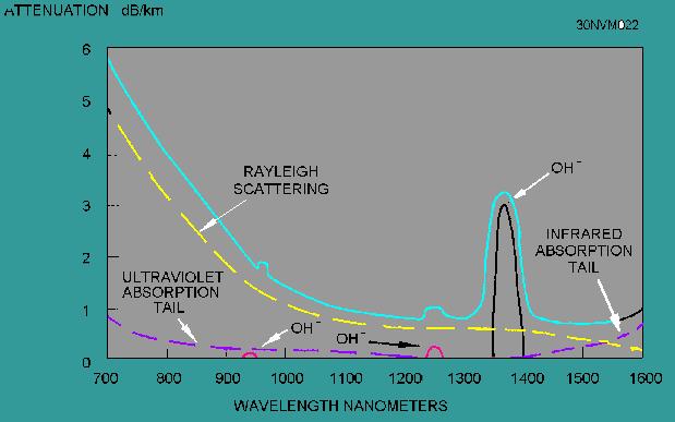
14 Loss and Bandwidth -- Attenuation Attenuation ranges from 0.1 db/km (single-mode silica fibers) to over 300 db/km (plastic fiber) There are two reasons for attenuation: Scattering; Absorption Attenuation (db/km) nm Window Attenuation (db) = OH Absorption Peak 10 log 10 P P nm Window 1550 nm Window Wavelength (nm)
15 Loss and Bandwidth Loss or attenuation is a limiting parameter in fiber optic systems Fiber optic transmission systems became competitive with electrical transmission lines only when losses were reduced to allow signal transmission over distances greater than 10 km Fiber attenuation can be described by the general relation: P out = P in α L where α is the power attenuation coefficient per unit length
16 Loss and Bandwidth Attenuation is conveniently expressed in terms of db/km α ( db km) 10 = log L 10 = log L 10 = L = 4.34α ( αl) log ( e) Power is often expressed in dbm (dbm is db from 1mW) P P out in Pine P αl 10 mw P = 10 mw = 10log10 = 10 dbm 1 mw P = 27 dbm = 1 mw 10 = 501 in 10 mw
17 Loss and Bandwidth Example: 10mW of power is launched into an optical fiber that has an attenuation of α=0.6 db/km. What is the received power after traveling a distance of 100 km? P out = ( 10 ) 1 mw = 10 nw Initial power is: P in = 10 dbm Received power is: P out = P α L in =10 dbm (0.6)(100) = -50 dbm
18 Loss and Bandwidth Example: 8mW of power is launched into an optical fiber that has an attenuation of α=0.6 db/km. The received power needs to be - 22dBm. What is the maximum transmission distance? Initial power is: P in = 10log 10 (8) = 9 dbm Received power is: P out = 1mW = 6.3 μw P out -P in = 9dBm - (-22dBm) = 31dB = 0.6 L L=51.7 km

19 Causes of Attenuation Attenuation, or losses, in a fiber link come from a variety of sources Bending losses Absorption Atomic Absorption Scattering Rayleigh Scattering Mie-Scattering Brillouin Scattering
20 Absorption The portion of attenuation resulting from the conversion of optical power into another energy form, such as heat. Every material absorbs some light energy The amount of absorption can vary greatly with wavelength It depends very strongly on the composition of a substance
21 Absorption is uniform The same amount of the same material always absorbs the same fraction of light at the same wavelength. Absorption is cumulative The total amount of material the light passes through Material absorbs the same fraction of the light for each unit length
22 Atomic Absorption The atoms of any material are capable of absorbing specific wavelengths of light. because of their electron orbital structure. As light passes along an optical fibre. more and more light is absorbed by the atoms as it continues on its path
23 Intrinsic Absorption is caused by basic fiber-material properties. Intrinsic absorption sets the minimal level of absorption.
24 Extrinsic Absorption. is caused by impurities introduced into the fiber material. Extrinsic absorption also occurs when hydroxyl ions (OH-) are introduced into the fiber. Water in silica glass forms (Si-OH) bond
25
26 Material Absorption Material absorption Intrinsic: caused by atomic resonance of the fiber material Ultra-violet Infra-red: primary intrinsic absorption for optical communications Extrinsic: caused by atomic absorptions of external particles in the fiber Primarily caused by the O-H bond in water that has absorption peaks at λ=2.8, 1.4, 0.93, 0.7 μm Interaction between O-H bond and SiO 2 glass at λ=1.24 μm The most important absorption peaks are at λ=1.4 μm and 1.24 μm
27 Scattering

28 Scattering The interaction of light with density fluctuations within a fiber The inhomogeneities of the refractive index of the media are responsible for this phenomena. Light traveling through the fiber interacts with the density areas. Light is then partially scattered in all directions.
29 Types of Scattering Rayleigh Scattering Mie-Scattering Brillouin Scattering Raman Scattering
30 Rayleigh Scattering Is the scattering of light by particles smaller than the wavelength of the light Occurs when the size of the density fluctuation (fiber defect) is less than one-tenth of the operating wavelength of light. is more effective at short wavelengths Therefore the light scattered down to the earth at a large angle with respect to the direction of the sun's light is predominantly in the blue end of the spectrum.


31 intensity of the scattered light is inversely proportional to the fourth power of the wavelength
32 Mie Scattering If the size of the defect is greater than one-tenth of the wavelength of light, the scattering mechanism is called Mie scattering. Mie scattering, caused by these large defects in the fiber core. scatters light out of the fiber core. However, in commercial fibers, the effects of Mie scattering are insignificant

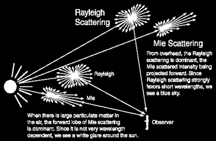
33 Rayleigh and Mie Scattering
34 Brillouin scattering spontaneous Brillouin scattering simulated Brillouin scattering


35 Spontaneous Brillouin scattering Scattering of light through Index variations induced by the pressure differences of an acoustic wave traveling through a transparent material. spontaneous Brillouin scattering, can also be described using the quantum physics: a photon from a pump lightwave is transformed in a new Stokes photon of lower frequency and a new phonon adding to the acoustic wave.
36 Absorption and Scattering Loss
37 External Losses Bending loss Radiation loss at bends in the optical fiber Insignificant unless R<1mm Larger radius of curvature becomes more significant if there are accumulated bending losses over a long distance Coupling and splicing loss Misalignment of core centers Tilt Air gaps End face reflections Mode mismatches
38 BENDING LOSSES
39 BENDING RADIUS The bend radius that causes loss due to light leaking from the core. When you exceed the minimum bend radius, your signal strength will drop. Typical radius is three to five inches.

40 Microbends Small microscopic bends Microbend loss increases attenuation because low-order modes become coupled with high-order modes that are naturally lossy Loss caused by microbending can still occur even if the fiber is cabled correctly
41 Macrobend losses Radius of curvature is large compared to the fiber diameter. During installation, if fibers are bent too sharply, macrobend losses will occur
42 Loss on Standard Optical Fiber Wavelength SMF / nm 1.8 db/km 2.72 db/km 1300 nm 0.35 db/km 0.52 db/km 1380 nm 0.50 db/km 0.92 db/km 1550 nm 0.19 db/km 0.29 db/km
43 Indoor/Outdoor cables
44 Dispersion Dispersive medium: velocity of propagation depends on frequency Dispersion causes temporal pulse spreading Pulse overlap results in indistinguishable data Inter symbol interference (ISI) Dispersion is related to the velocity of the pulse
45 Material Dispersion Since optical sources do not emit just a single frequency but a band of frequencies, then there may be propagation delay differences between the different spectral components of the transmitted signal. The delay differences may be caused by material dispersion and waveguide dispersion. For a source with rms spectral width σ λ and mean wavelength λ, the rms pulse broadening due to material dispersion σ m is given by σ L 2 σ λ λ m λ c dn 1 d 2
46 Material Dispersion The Material Dispersion for optical fibers is sometimes quoted as a value for 2 2 dn1 λ ( ) 2 dλ or simply 2 dn1 2 dλ It may be given in terms of a material dispersion parameter M defined as: 2 1 d m dn1 M τ λ = = Ld c d 2 λ λ expressed in units of ps nm -1 km -1 Where τ m is the pulse delay due to material dispersion
47 Example 2 2 dn1 A glass fiber exhibits material dispersion given by λ ( ) 2 dλ of Determine the material dispersion parameter at a wavelength of 0.85 μm, and estimate the rms pulse broadening per kilometer for a good LED source with an rms spectral width of 20nm at this wavelength.
48 Solution The material dispersion parameter may be obtained dn1 1 2 dn1 M = λ = λ c d 2 c d 2 λ λ λ = x x snm km 1 1 = 98.1psnm km 1 1 The rms pulse broadening is given as 2 σ L dn1 σ λ m λ 2 c d λ Therefore in terms of material dispersion parameter M σ m σ λ LM Hence, the rms pulse broadning per kilometer due to material dispersion σ 12 1 m(1 km) = x x x = 1.96nskm
49 Example 2 Estimate the rms pulse broadening per kilometer for the fiber in the above example when the optical source used is an injection laser with a relative spectral width σ λ /λ of at a wavelength of 0.85 μm
50 Solution The rms spectral width may be obtained from the relative spectral width by σ λ = λ = x 0.85 x 10-6 = 1.02nm The rms pulse broadening in terms of material dispersion parameter is given by σ σ m λ LM σ m = 1.02 x 1x 98.1 x = 0.10 ns km -1 Hence the rms pulse broadening is reduced by a factor of 20 compared with the LED source in the previous example
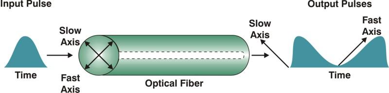
51 Polarization mode Dispersion (PMD) Polarization mode dispersion (PMD) is another complex optical effect that can occur in singlemode optical fibers. Single-mode fibers support two perpendicular polarizations of the original transmitted signal. If a were perfectly round and free from all stresses, both polarization modes would propagate at exactly the same speed, resulting in zero PMD.
52 Polarization mode dispersion (PMD) However, practical fibers are not perfect, thus, the two perpendicular polarizations may travel at different speeds and, consequently, arrive at the end of the fiber at different times. The fiber is said to have a fast axis, and a slow axis. The difference in arrival times, normalized with length, is known as PMD (ps/km 0.5 ).
53 Polarization Mode Dispersion (PMD) Polarization mode dispersion is an inherent property of all optical media. It is caused by the difference in the propagation velocities of light in the orthogonal principal polarization states of the transmission medium. The net effect is that if an optical pulse contains both polarization components, then the different polarization components will travel at different speeds and arrive at different times, smearing the received optical signal.
54

55 NUST Institute Of Information Technology
56

57 Non-flammable No fire hazard Low power saves provider and money.
58 Assignment The material dispersion parameter for a glass fiber is 20 ps nm -1 km -1 at a wavelength of 1.5 μm. Estimate the pulse broadening due to material dispersion within the fiber when a light is launched from an injection laser source with a peak wavelength of 1.5 μm and an rms spectral width of 2nm into a 30 km length of fiber. The material distribution in an optical fiber defined d 2 n 1 /dλ 2 is 4.0 x 10⁻² μm -2. Estimate the pulse broadening per kilometer due to material dispersion within the fiber when it is illuminated with an LED source with a peak wavelength of 0.9 μm and an rms spectral width of 45 nm. Questions 2.2, 2.4, 2.5 Ramaswami
UNIT-II : SIGNAL DEGRADATION IN OPTICAL FIBERS
 UNIT-II : SIGNAL DEGRADATION IN OPTICAL FIBERS The Signal Transmitting through the fiber is degraded by two mechanisms. i) Attenuation ii) Dispersion Both are important to determine the transmission characteristics
Chapter 3 Signal Degradation in Optical Fibers
 What about the loss in optical fiber? Why and to what degree do optical signals gets distorted as they propagate along a fiber? Fiber links are limited by in path length by attenuation and pulse distortion.
Types of losses in optical fiber cable are: Due to attenuation, the power of light wave decreases exponentially with distance.
 UNIT-II TRANSMISSION CHARACTERISTICS OF OPTICAL FIBERS SIGNAL ATTENUATION: Signal attenuation in an optical fiber is defined as the decrease in light power during light propagation along an optical fiber.
The absorption of the light may be intrinsic or extrinsic
 Attenuation Fiber Attenuation Types 1- Material Absorption losses 2- Intrinsic Absorption 3- Extrinsic Absorption 4- Scattering losses (Linear and nonlinear) 5- Bending Losses (Micro & Macro) Material
Guided Propagation Along the Optical Fiber. Xavier Fernando Ryerson Comm. Lab
 Guided Propagation Along the Optical Fiber Xavier Fernando Ryerson Comm. Lab The Nature of Light Quantum Theory Light consists of small particles (photons) Wave Theory Light travels as a transverse electromagnetic
Guided Propagation Along the Optical Fiber
 Guided Propagation Along the Optical Fiber The Nature of Light Quantum Theory Light consists of small particles (photons) Wave Theory Light travels as a transverse electromagnetic wave Ray Theory Light
Section B Lecture 5 FIBER CHARACTERISTICS
 Section B Lecture 5 FIBER CHARACTERISTICS Material absorption Losses Material absorption is a loss mechanism related to material composition and fabrication process for the fiber. This results in dissipation
Absorption: in an OF, the loss of Optical power, resulting from conversion of that power into heat.
 Absorption: in an OF, the loss of Optical power, resulting from conversion of that power into heat. Scattering: The changes in direction of light confined within an OF, occurring due to imperfection in
Losses and Dispersion in Waveguides
 Losses and Dispersion in Waveguides Wei-Chih WangInstitute of Nanoengineeirng and Microsystems National Tsing Hua University 1 Week 13 Course Website: http://courses.washington.edu/me557/sensors Reading
Guided Propagation Along the Optical Fiber. Xavier Fernando Ryerson University
 Guided Propagation Along the Optical Fiber Xavier Fernando Ryerson University The Nature of Light Quantum Theory Light consists of small particles (photons) Wave Theory Light travels as a transverse electromagnetic
Optical systems have carrier frequencies of ~100 THz. This corresponds to wavelengths from µm.
 Introduction A communication system transmits information form one place to another. This could be from one building to another or across the ocean(s). Many systems use an EM carrier wave to transmit information.
UNIT Write notes on broadening of pulse in the fiber dispersion?
 UNIT 3 1. Write notes on broadening of pulse in the fiber dispersion? Ans: The dispersion of the transmitted optical signal causes distortion for both digital and analog transmission along optical fibers.
Fiber Optic Communications Communication Systems
 INTRODUCTION TO FIBER-OPTIC COMMUNICATIONS A fiber-optic system is similar to the copper wire system in many respects. The difference is that fiber-optics use light pulses to transmit information down
NEW YORK CITY COLLEGE of TECHNOLOGY
 NEW YORK CITY COLLEGE of TECHNOLOGY THE CITY UNIVERSITY OF NEW YORK DEPARTMENT OF ELECTRICAL AND TELECOMMUNICATIONS ENGINEERING TECHNOLOGY Course : Prepared by: TCET 4102 Fiber-optic communications Module
Fiberoptic and Waveguide Sensors
 Fiberoptic and Waveguide Sensors Wei-Chih Wang Department of Mecahnical Engineering University of Washington Optical sensors Advantages: -immune from electromagnetic field interference (EMI) - extreme
Examination Optoelectronic Communication Technology. April 11, Name: Student ID number: OCT1 1: OCT 2: OCT 3: OCT 4: Total: Grade:
 Examination Optoelectronic Communication Technology April, 26 Name: Student ID number: OCT : OCT 2: OCT 3: OCT 4: Total: Grade: Declaration of Consent I hereby agree to have my exam results published on
Waveguides and Optical Fibers
 Waveguides and Optical Fibers Dielectric Waveguides Light Light Light n n Light n > n A planar dielectric waveguide has a central rectangular region of higher refractive index n than the surrounding region
The electric field for the wave sketched in Fig. 3-1 can be written as
 ELECTROMAGNETIC WAVES Light consists of an electric field and a magnetic field that oscillate at very high rates, of the order of 10 14 Hz. These fields travel in wavelike fashion at very high speeds.
Optical behavior. Reading assignment. Topic 10
 Reading assignment Optical behavior Topic 10 Askeland and Phule, The Science and Engineering of Materials, 4 th Ed.,Ch. 0. Shackelford, Materials Science for Engineers, 6 th Ed., Ch. 16. Chung, Composite
τ mod = T modal = longest ray path shortest ray path n 1 L 1 = L n 2 1
 S. Blair February 15, 2012 23 2.2. Pulse dispersion Pulse dispersion is the spreading of a pulse as it propagates down an optical fiber. Pulse spreading is an obvious detrimental effect that limits the
2. The Basic principle of optical fibre (Or) Working principle of optical fibre (or) Total internal reflection
 Working principle of optical fibre (or) Total internal reflection") Introduction Fibre optics deals with the light propagation through thin glass fibres. Fibre optics plays an important role in the field of communication to transmit voice, television and digital data signals
Introduction Fibre optics deals with the light propagation through thin glass fibres. Fibre optics plays an important role in the field of communication to transmit voice, television and digital data signals
Advanced Fibre Testing: Paving the Way for High-Speed Networks. Trevor Nord Application Specialist JDSU (UK) Ltd
 Ltd") Advanced Fibre Testing: Paving the Way for High-Speed Networks Trevor Nord Application Specialist JDSU (UK) Ltd Fibre Review Singlemode Optical Fibre Elements of Loss Fibre Attenuation - Caused by scattering
Advanced Fibre Testing: Paving the Way for High-Speed Networks Trevor Nord Application Specialist JDSU (UK) Ltd Fibre Review Singlemode Optical Fibre Elements of Loss Fibre Attenuation - Caused by scattering
DIELECTRIC WAVEGUIDES and OPTICAL FIBERS
 DIELECTRIC WAVEGUIDES and OPTICAL FIBERS Light Light Light n 2 n 2 Light n 1 > n 2 A planar dielectric waveguide has a central rectangular region of higher refractive index n 1 than the surrounding region
There are lots of problems or challenges with fiber, Attenuation, Reflections, Dispersion and so on. So here we will look at these problems.
 The Hard theory The Hard Theory An introduction to fiber, should also include a section with some of the difficult theory. So if everything else in the book was very easily understood, then this section
EE 233. LIGHTWAVE. Chapter 2. Optical Fibers. Instructor: Ivan P. Kaminow
 EE 233. LIGHTWAVE SYSTEMS Chapter 2. Optical Fibers Instructor: Ivan P. Kaminow PLANAR WAVEGUIDE (RAY PICTURE) Agrawal (2004) Kogelnik PLANAR WAVEGUIDE a = (n s 2 - n c2 )/ (n f 2 - n s2 ) = asymmetry;
Optical Fiber. n 2. n 1. θ 2. θ 1. Critical Angle According to Snell s Law
 ECE 271 Week 10 Critical Angle According to Snell s Law n 1 sin θ 1 = n 1 sin θ 2 θ 1 and θ 2 are angle of incidences The angle of incidence is measured with respect to the normal at the refractive boundary
Lecture 3 Fiber Optical Communication Lecture 3, Slide 1
 Lecture 3 Dispersion in single-mode fibers Material dispersion Waveguide dispersion Limitations from dispersion Propagation equations Gaussian pulse broadening Bit-rate limitations Fiber losses Fiber Optical
COM 46: ADVANCED COMMUNICATIONS jfm 07 FIBER OPTICS
 FIBER OPTICS Fiber optics is a unique transmission medium. It has some unique advantages over conventional communication media, such as copper wire, microwave or coaxial cables. The major advantage is
Optical fibre. Principle and applications
 Optical fibre Principle and applications Circa 2500 B.C. Earliest known glass Roman times-glass drawn into fibers Venice Decorative Flowers made of glass fibers 1609-Galileo uses optical telescope 1626-Snell
UNIT List the requirements that be satisfied by materials used to manufacture optical fiber? ANS: Fiber Materials
 UNIT- 2 1. List the requirements that be satisfied by materials used to manufacture optical fiber? ANS: Fiber Materials Most of the fibers are made up of glass consisting of either Silica (SiO 2 ) or.silicate.
Photonics and Optical Communication
 Photonics and Optical Communication (Course Number 300352) Spring 2007 Dr. Dietmar Knipp Assistant Professor of Electrical Engineering http://www.faculty.iu-bremen.de/dknipp/ 1 Photonics and Optical Communication
EC Optical Communication And Networking TWO MARKS QUESTION AND ANSWERS UNIT -1 INTRODUCTION
 EC6702 - Optical Communication And Networking TWO MARKS QUESTION AND ANSWERS UNIT -1 INTRODUCTION Ray Theory Transmission 1. Write short notes on ray optics theory. Laws governing the nature of light are
is a method of transmitting information from one place to another by sending light through an optical fiber. The light forms an electromagnetic
 is a method of transmitting information from one place to another by sending light through an optical fiber. The light forms an electromagnetic carrier wave that is modulated to carry information. The
1. Evolution Of Fiber Optic Systems
 OPTICAL FIBER COMMUNICATION UNIT-I : OPTICAL FIBERS STRUCTURE: 1. Evolution Of Fiber Optic Systems The operating range of optical fiber system term and the characteristics of the four key components of
Chapter 9 GUIDED WAVE OPTICS
 [Reading Assignment, Hecht 5.6] Chapter 9 GUIDED WAVE OPTICS Optical fibers The step index circular waveguide is the most common fiber design for optical communications plastic coating (sheath) core cladding
Lecture 10. Dielectric Waveguides and Optical Fibers
 Lecture 10 Dielectric Waveguides and Optical Fibers Slab Waveguide, Modes, V-Number Modal, Material, and Waveguide Dispersions Step-Index Fiber, Multimode and Single Mode Fibers Numerical Aperture, Coupling
Photonics and Optical Communication Spring 2005
 Photonics and Optical Communication Spring 2005 Final Exam Instructor: Dr. Dietmar Knipp, Assistant Professor of Electrical Engineering Name: Mat. -Nr.: Guidelines: Duration of the Final Exam: 2 hour You
Industrial Automation
 OPTICAL FIBER. SINGLEMODE OR MULTIMODE It is important to understand the differences between singlemode and multimode fiber optics before selecting one or the other at the start of a project. Its different
Fiber Optic Communication Systems. Unit-05: Types of Fibers. https://sites.google.com/a/faculty.muet.edu.pk/abdullatif
 Unit-05: Types of Fibers https://sites.google.com/a/faculty.muet.edu.pk/abdullatif Department of Telecommunication, MUET UET Jamshoro 1 Optical Fiber Department of Telecommunication, MUET UET Jamshoro
SIGNAL DEGRADATION IN OPTICAL FIBERS
 Volume Issue January 04, ISSN 348 8050 SIGNAL DEGRADATION IN OPTICAL FIBERS Gyan Prakash Pal, Manishankar Gupta,,, Assistant Professor, Electronics & Communication Engineering Department, Shanti Institute
Lecture 8 Fiber Optical Communication Lecture 8, Slide 1
 Lecture 8 Bit error rate The Q value Receiver sensitivity Sensitivity degradation Extinction ratio RIN Timing jitter Chirp Forward error correction Fiber Optical Communication Lecture 8, Slide Bit error
Optics and Images. Lenses and Mirrors. Matthew W. Milligan
 Optics and Images Lenses and Mirrors Light: Interference and Optics I. Light as a Wave - wave basics review - electromagnetic radiation II. Diffraction and Interference - diffraction, Huygen s principle
2 in the multipath dispersion of the optical fibre. (b) Discuss the merits and drawbacks of cut bouls method of measurement of alternation.
 Discuss the merits and drawbacks of cut bouls method of measurement of alternation.") B.TECH IV Year I Semester (R09) Regular Examinations, November 2012 1 (a) Derive an expression for multiple time difference tt 2 in the multipath dispersion of the optical fibre. (b) Discuss the merits
B.TECH IV Year I Semester (R09) Regular Examinations, November 2012 1 (a) Derive an expression for multiple time difference tt 2 in the multipath dispersion of the optical fibre. (b) Discuss the merits
Application Note 5596
 Polymer Optical Fiber (POF) Application Note 5596 Table of Contents Part 1. POF Overview 1 Introduction 2 Principle of operation 2 Numerical Aperture 2 Modes 3 Attenuation 4 Rayleigh scattering 4 Absorption
Chapter 22 Quiz. Snell s Law describes: (a) Huygens construction (b) Magnification (c) Reflection (d) Refraction. PHY2054: Chapter 22 9
 Huygens construction (b) Magnification (c) Reflection (d) Refraction. PHY2054: Chapter 22 9") Snell s Law describes: (a) Huygens construction (b) Magnification (c) Reflection (d) Refraction Chapter 22 Quiz PHY2054: Chapter 22 9 Chapter 22 Quiz For refracted light rays, the angle of refraction:
Snell s Law describes: (a) Huygens construction (b) Magnification (c) Reflection (d) Refraction Chapter 22 Quiz PHY2054: Chapter 22 9 Chapter 22 Quiz For refracted light rays, the angle of refraction:
Department of Electrical Engineering and Computer Science
 MASSACHUSETTS INSTITUTE of TECHNOLOGY Department of Electrical Engineering and Computer Science 6.161/6637 Practice Quiz 2 Issued X:XXpm 4/XX/2004 Spring Term, 2004 Due X:XX+1:30pm 4/XX/2004 Please utilize
Photonics and Fiber Optics
 1 UNIT V Photonics and Fiber Optics Part-A 1. What is laser? LASER is the acronym for Light Amplification by Stimulated Emission of Radiation. The absorption and emission of light by materials has been
SKP Engineering College
 SKP Engineering College Tiruvannamalai 606611 A Course Material on Optical Communication and Networks By M.Mageshbabu Assistant Professor Electronics and Communication Engineering Department Electronics
Chapter 18: Fiber Optic and Laser Technology
 Chapter 18: Fiber Optic and Laser Technology Chapter 18 Objectives At the conclusion of this chapter, the reader will be able to: Describe the construction of fiber optic cable. Describe the propagation
Geometrical Optics Fiber optics The eye
 Phys 322 Lecture 16 Chapter 5 Geometrical Optics Fiber optics The eye First optical communication Alexander Graham Bell 1847-1922 1880: photophone 4 years after inventing a telephone! Fiberoptics: first
How to Speak Fiber Geek Article 2 Critical Optical Parameters Attenuation
 Article 2 Critical Optical Parameters Attenuation Welcome back, Fiber Geeks! Article 1 in this series highlighted some bandwidth demand drivers and introductory standards information. The article also
Lecture 12: Curvature and Refraction Radar Equation for Point Targets (Rinehart Ch3-4)
") MET 4410 Remote Sensing: Radar and Satellite Meteorology MET 5412 Remote Sensing in Meteorology Lecture 12: Curvature and Refraction Radar Equation for Point Targets (Rinehart Ch3-4) Radar Wave Propagation
MET 4410 Remote Sensing: Radar and Satellite Meteorology MET 5412 Remote Sensing in Meteorology Lecture 12: Curvature and Refraction Radar Equation for Point Targets (Rinehart Ch3-4) Radar Wave Propagation
EKT 465 OPTICAL COMMUNICATION SYSTEM. Chapter 2 OPTICAL FIBER COMMUNICATIONS
 EKT 465 OPTICAL COMMUNICATION SYSTEM Chapter 2 OPTICAL FIBER COMMUNICATIONS SEMESTER 1-2017/18 3 Credit Hours 222.3 Gbps pada 2017, daripada 6.4Gbps pada 2012 10/3/2017 2 Light Propagation & Transmission
Total care for networks. Introduction to Dispersion
 Introduction to Dispersion Introduction to PMD Version1.0- June 01, 2000 Copyright GN Nettest 2000 Introduction To Dispersion Contents Definition of Dispersion Chromatic Dispersion Polarization Mode Dispersion
Optical Fiber Communication
 A Seminar report On Optical Fiber Communication Submitted in partial fulfillment of the requirement for the award of degree Of Mechanical SUBMITTED TO: www.studymafia.org SUBMITTED BY: www.studymafia.org
UNIT I INTRODUCTION TO OPTICAL FIBERS
 UNIT I INTRODUCTION TO OPTICAL FIBERS 9 Evolution of fiber optic system Element of an Optical Fiber Transmission link Total internal reflection Acceptance angle Numerical aperture Skew rays Ray Optics
JFOC-BSG2D MODEL:JFOC-BSG2D. optic.com. For detailed inquiry please contact our sales team at:
 JFOC-BSG2D MODEL:JFOC-BSG2D For detailed inquiry please contact our sales team at: market@jfiber optic.com Description : JFOC-BSG2D dispersion unshifted singlemode fiber is designed specially for optical
DISPERSION COMPENSATING FIBER
 DISPERSION COMPENSATING FIBER Dispersion-Compensating SM Fiber for Telecom Wavelengths (1520-1625 nm) DCF38 is Specifically Designed to Compensate Corning SMF-28e+ Fiber Short Pulse Broad Pulse due to
Analysis of Self Phase Modulation Fiber nonlinearity in Optical Transmission System with Dispersion
 36 Analysis of Self Phase Modulation Fiber nonlinearity in Optical Transmission System with Dispersion Supreet Singh 1, Kulwinder Singh 2 1 Department of Electronics and Communication Engineering, Punjabi
Chapter 8. Digital Links
 Chapter 8 Digital Links Point-to-point Links Link Power Budget Rise-time Budget Power Penalties Dispersions Noise Content Photonic Digital Link Analysis & Design Point-to-Point Link Requirement: - Data
Dispersion and Ultrashort Pulses II
 Dispersion and Ultrashort Pulses II Generating negative groupdelay dispersion angular dispersion Pulse compression Prisms Gratings Chirped mirrors Chirped vs. transform-limited A transform-limited pulse:
Fibre Optic Sensors: basic principles and most common applications
 SMR 1829-21 Winter College on Fibre Optics, Fibre Lasers and Sensors 12-23 February 2007 Fibre Optic Sensors: basic principles and most common applications (PART 2) Hypolito José Kalinowski Federal University
Chapter 2: Fiber Optics as a communication medium
 Chapter 2: Fiber Optics as a communication medium 2.1 Fiber Fabrication: Basically, fiber manufacturers use two methods to fabricate multimode and single mode glass fibers. One method is vapor phase oxidation,
MAHALAKSHMI ENGINEERING COLLEGE TIRUCHIRAPALLI
 MAHALAKSHMI ENGINEERING COLLEGE TIRUCHIRAPALLI - 621213 DEPARTMENT : ECE SUBJECT NAME : OPTICAL COMMUNICATION & NETWORKS SUBJECT CODE : EC 2402 UNIT II: TRANSMISSION CHARACTERISTICS OF OPTICAL FIBERS PART
FCQ1064-APC 1064 nm 1x4 Narrowband Coupler. Mounted on
 1 X 4 SINGLE MODE FIBER OPTIC COUPLERS Wavelengths from 560 nm to 1550 nm Available 25:25:25:25 Split Ratio Terminated with 2.0 mm Narrow Key or Connectors Use for Splitting Signals FCQ1064-APC 1064 nm
Channel. Muhammad Ali Jinnah University, Islamabad Campus, Pakistan. Multi-Path Fading. Dr. Noor M Khan EE, MAJU
 Instructor: Prof. Dr. Noor M. Khan Department of Electronic Engineering, Muhammad Ali Jinnah University, Islamabad Campus, Islamabad, PAKISTAN Ph: +9 (51) 111-878787, Ext. 19 (Office), 186 (Lab) Fax: +9
Introduction to Fiber Optics
 Introduction to Fiber Optics Dr. Anurag Srivastava Atal Bihari Vajpayee Indian Institute of Information Technology and Manegement, Gwalior Milestones in Electrical Communication 1838 Samuel F.B. Morse
Vågrörelselära och optik
 Vågrörelselära och optik Kapitel 33 - Ljus 1 Vågrörelselära och optik Kurslitteratur: University Physics by Young & Friedman Harmonisk oscillator: Kapitel 14.1 14.4 Mekaniska vågor: Kapitel 15.1 15.8 Ljud
Refraction is the change in speed of a wave due to the wave entering a different medium. light travels at different speeds in different media
 Refraction Refraction is the change in speed of a wave due to the wave entering a different medium light travels at different speeds in different media this causes light to bend as it passes from one substance
Fiber Optic Communication Link Design
 Fiber Optic Communication Link Design By Michael J. Fujita, S.K. Ramesh, PhD, Russell L. Tatro Abstract The fundamental building blocks of an optical fiber transmission link are the optical source, the
Fiber designs for high figure of merit and high slope dispersion compensating fibers
 25 Springer Science+Business Media Inc. DOI: 1.17/s1297-5-61-1 Originally published in J. Opt. Fiber. Commun. Rep. 3, 25 6 (25) Fiber designs for high figure of merit and high slope dispersion compensating
Notes on Optical Amplifiers
 Notes on Optical Amplifiers Optical amplifiers typically use energy transitions such as those in atomic media or electron/hole recombination in semiconductors. In optical amplifiers that use semiconductor
Light sources can be natural or artificial (man-made)
") Light The Sun is our major source of light Light sources can be natural or artificial (man-made) People and insects do not see the same type of light - people see visible light - insects see ultraviolet
Light The Sun is our major source of light Light sources can be natural or artificial (man-made) People and insects do not see the same type of light - people see visible light - insects see ultraviolet
PROJECT REPORT COUPLING OF LIGHT THROUGH FIBER PHY 564 SUBMITTED BY: GAGANDEEP KAUR ( )
") PROJECT REPORT COUPLING OF LIGHT THROUGH FIBER PHY 564 SUBMITTED BY: GAGANDEEP KAUR (952549116) 1 INTRODUCTION: An optical fiber (or fiber) is a glass or plastic fiber that carries light along its length.
PROJECT REPORT COUPLING OF LIGHT THROUGH FIBER PHY 564 SUBMITTED BY: GAGANDEEP KAUR (952549116) 1 INTRODUCTION: An optical fiber (or fiber) is a glass or plastic fiber that carries light along its length.
Multi-Path Fading Channel
 Instructor: Prof. Dr. Noor M. Khan Department of Electronic Engineering, Muhammad Ali Jinnah University, Islamabad Campus, Islamabad, PAKISTAN Ph: +9 (51) 111-878787, Ext. 19 (Office), 186 (Lab) Fax: +9
Lectureo5 FIBRE OPTICS. Unit-03
 Lectureo5 FIBRE OPTICS Unit-03 INTRODUCTION FUNDAMENTAL IDEAS ABOUT OPTICAL FIBRE Multimode Fibres Multimode Step Index Fibres Multimode Graded Index Fibres INTRODUCTION In communication systems, there
Chapter 8. Wavelength-Division Multiplexing (WDM) Part II: Amplifiers
 Part II: Amplifiers") Chapter 8 Wavelength-Division Multiplexing (WDM) Part II: Amplifiers Introduction Traditionally, when setting up an optical link, one formulates a power budget and adds repeaters when the path loss exceeds
Chapter 8 Wavelength-Division Multiplexing (WDM) Part II: Amplifiers Introduction Traditionally, when setting up an optical link, one formulates a power budget and adds repeaters when the path loss exceeds
=, where f is focal length of a lens (positive for convex. Equations: Lens equation
 Physics 1230 Light and Color : Exam #1 Your full name: Last First & middle General information: This exam will be worth 100 points. There are 10 multiple choice questions worth 5 points each (part 1 of
CHAPTER 5 SPECTRAL EFFICIENCY IN DWDM
 61 CHAPTER 5 SPECTRAL EFFICIENCY IN DWDM 5.1 SPECTRAL EFFICIENCY IN DWDM Due to the ever-expanding Internet data traffic, telecommunication networks are witnessing a demand for high-speed data transfer.
High Performance Dispersion and Dispersion Slope Compensating Fiber Modules for Non-zero Dispersion Shifted Fibers
 High Performance Dispersion and Dispersion Slope Compensating Fiber Modules for Non-zero Dispersion Shifted Fibers Kazuhiko Aikawa, Ryuji Suzuki, Shogo Shimizu, Kazunari Suzuki, Masato Kenmotsu, Masakazu
LSSS-OF FOR. Zero Water Peak Single-Mode Optical Fiber. (Reference: ITU-T G.652.D) Prepared by Eun Kyung Min Engineer Passive Solution Team
 Prepared by Eun Kyung Min Engineer Passive Solution Team") PAGE : 1 OF 6 LSSS-OF0007-00 FOR Zero Water Peak Single-Mode Optical Fiber (Reference: ITU-T G.652.D) Prepared by Eun Kyung Min Engineer Passive Solution Team Checked by Yu-Hyoung Lee Manager Passive Solution
PAGE : 1 OF 6 LSSS-OF0007-00 FOR Zero Water Peak Single-Mode Optical Fiber (Reference: ITU-T G.652.D) Prepared by Eun Kyung Min Engineer Passive Solution Team Checked by Yu-Hyoung Lee Manager Passive Solution
Chapter 12: Optical Amplifiers: Erbium Doped Fiber Amplifiers (EDFAs)
") Chapter 12: Optical Amplifiers: Erbium Doped Fiber Amplifiers (EDFAs) Prof. Dr. Yaocheng SHI ( 时尧成 ) yaocheng@zju.edu.cn http://mypage.zju.edu.cn/yaocheng 1 Traditional Optical Communication System Loss
Chapter 12: Optical Amplifiers: Erbium Doped Fiber Amplifiers (EDFAs) Prof. Dr. Yaocheng SHI ( 时尧成 ) yaocheng@zju.edu.cn http://mypage.zju.edu.cn/yaocheng 1 Traditional Optical Communication System Loss
SPECIFICATION. FOR SINGLE-MODE OPTICAL FIBER (FutureGuide -SR15E)
") Fujikura DATE Aug. 18, 2008 NO. JFS-00052A Supersedes JFS-00052 Messrs. SPECIFICATION FOR SINGLE-MODE OPTICAL FIBER (FutureGuide -SR15E) Prepared by H. KIKUCHI Manager Optical Fiber and Cable Dept. Global
Fujikura DATE Aug. 18, 2008 NO. JFS-00052A Supersedes JFS-00052 Messrs. SPECIFICATION FOR SINGLE-MODE OPTICAL FIBER (FutureGuide -SR15E) Prepared by H. KIKUCHI Manager Optical Fiber and Cable Dept. Global
Fiber Optic Principles. Oct-09 1
 Fiber Optic Principles Oct-09 1 Fiber Optic Basics Optical fiber Active components Attenuation Power budget Bandwidth Oct-09 2 Reference www.flukenetworks.com/fiber Handbook Fiber Optic Technologies (Vivec
Lecture 6 Fiber Optical Communication Lecture 6, Slide 1
 Lecture 6 Optical transmitters Photon processes in light matter interaction Lasers Lasing conditions The rate equations CW operation Modulation response Noise Light emitting diodes (LED) Power Modulation
Bragg and fiber gratings. Mikko Saarinen
 Bragg and fiber gratings Mikko Saarinen 27.10.2009 Bragg grating - Bragg gratings are periodic perturbations in the propagating medium, usually periodic variation of the refractive index - like diffraction
Optical networking. Emilie CAMISARD GIP RENATER Optical technologies engineer Advanced IP Services
 Optical networking Emilie CAMISARD GIP RENATER Optical technologies engineer Advanced IP Services Agenda Optical fibre principle Time Division Multiplexing (TDM) Wavelength Division Multiplexing (WDM)
OPTICAL NETWORKS. Building Blocks. A. Gençata İTÜ, Dept. Computer Engineering 2005
 OPTICAL NETWORKS Building Blocks A. Gençata İTÜ, Dept. Computer Engineering 2005 Introduction An introduction to WDM devices. optical fiber optical couplers optical receivers optical filters optical amplifiers
Lab #1 HANDLING FIBERS, NUMERICAL APERTURE
 Lab #1 HANDLING FIBERS, NUMERICAL APERTURE OBJECTIVES: In this project, you will learn how to prepare fiber ends for use in the laboratory. You will be able to observe the geometry of a fiber and you will
Multimode Optical Fiber
 Multimode Optical Fiber 1 OBJECTIVE Determine the optical modes that exist for multimode step index fibers and investigate their performance on optical systems. 2 PRE-LAB The backbone of optical systems
Performance analysis of Erbium Doped Fiber Amplifier at different pumping configurations
 Performance analysis of Erbium Doped Fiber Amplifier at different pumping configurations Mayur Date M.E. Scholar Department of Electronics and Communication Ujjain Engineering College, Ujjain (M.P.) datemayur3@gmail.com
OPTI510R: Photonics. Khanh Kieu College of Optical Sciences, University of Arizona Meinel building R.626
 OPTI510R: Photonics Khanh Kieu College of Optical Sciences, University of Arizona kkieu@optics.arizona.edu Meinel building R.626 Announcements Homework #3 is due today No class Monday, Feb 26 Pre-record
Single-photon excitation of morphology dependent resonance
 Single-photon excitation of morphology dependent resonance 3.1 Introduction The examination of morphology dependent resonance (MDR) has been of considerable importance to many fields in optical science.
# DEFINITIONS TERMS. 2) Electrical energy that has escaped into free space. Electromagnetic wave
 Electrical energy that has escaped into free space. Electromagnetic wave") CHAPTER 14 ELECTROMAGNETIC WAVE PROPAGATION # DEFINITIONS TERMS 1) Propagation of electromagnetic waves often called radio-frequency (RF) propagation or simply radio propagation. Free-space 2) Electrical
CHAPTER 14 ELECTROMAGNETIC WAVE PROPAGATION # DEFINITIONS TERMS 1) Propagation of electromagnetic waves often called radio-frequency (RF) propagation or simply radio propagation. Free-space 2) Electrical
Intensity Modulation. Wei-Chih Wang Department of Mechanical Engineering University of Washington. W. Wang
 Intensity Modulation Wei-Chih Wang Department of Mechanical Engineering University of Washington Why Intensity Modulation Simple optical setup Broadband or mono-chormatic light source Less sensitive but
GIST OF THE UNIT BASED ON DIFFERENT CONCEPTS IN THE UNIT (BRIEFLY AS POINT WISE). RAY OPTICS
. RAY OPTICS") 209 GIST OF THE UNIT BASED ON DIFFERENT CONCEPTS IN THE UNIT (BRIEFLY AS POINT WISE). RAY OPTICS Reflection of light: - The bouncing of light back into the same medium from a surface is called reflection
209 GIST OF THE UNIT BASED ON DIFFERENT CONCEPTS IN THE UNIT (BRIEFLY AS POINT WISE). RAY OPTICS Reflection of light: - The bouncing of light back into the same medium from a surface is called reflection
2. Pulsed Acoustic Microscopy and Picosecond Ultrasonics
 1st International Symposium on Laser Ultrasonics: Science, Technology and Applications July 16-18 2008, Montreal, Canada Picosecond Ultrasonic Microscopy of Semiconductor Nanostructures Thomas J GRIMSLEY
Teaching fiber-optic communications in engineering technology programs by virtual collaboration with industry
 Teaching fiber-optic communications in engineering technology programs by virtual collaboration with industry Djafar K. Mynbaev New York City College of Technology of the City University of New York, 300
Chapter 18 Optical Elements
 Chapter 18 Optical Elements GOALS When you have mastered the content of this chapter, you will be able to achieve the following goals: Definitions Define each of the following terms and use it in an operational
FIBER OPTICS. Prof. R.K. Shevgaonkar. Department of Electrical Engineering. Indian Institute of Technology, Bombay. Lecture: 37
 FIBER OPTICS Prof. R.K. Shevgaonkar Department of Electrical Engineering Indian Institute of Technology, Bombay Lecture: 37 Introduction to Raman Amplifiers Fiber Optics, Prof. R.K. Shevgaonkar, Dept.