EE 233. LIGHTWAVE. Chapter 2. Optical Fibers. Instructor: Ivan P. Kaminow
|
|
|
- Bennett Hancock
- 5 years ago
- Views:
Transcription

1 EE 233. LIGHTWAVE SYSTEMS Chapter 2. Optical Fibers Instructor: Ivan P. Kaminow
2 PLANAR WAVEGUIDE (RAY PICTURE)
3 Agrawal (2004)
4 Kogelnik PLANAR WAVEGUIDE a = (n s 2 - n c2 )/ (n f 2 - n s2 ) = asymmetry; n f > n s > n c b = (N 2 - n s2 )/ (n f 2 - n s2 ) = normalized guide index N ~ n s + b(n f - n s ) = effective index [n f ~ n s ] V = kh (n f 2 - n s2 ) 1/2 = normalized frequency h
5 Waveguide Basics Light is guided by total internal reflection Transverse modes: For a given guide dimension and index profile, there exists an integer number of propagating modes. What is a mode? For every transverse mode, a standing wave is established in the transverse direction The higher the mode number, The sharper the guiding angle The smaller the propagation constant in the z (propagating direction) k k z =! ) = ' ( # n1 = kx + k y + kz " 0 & $ % 2
6 WAVE EQUATION
7 Agrawal (2004)
8 Kogelnik PLANAR WAVEGUIDE a = (n s 2 - n c2 )/ (n f 2 - n s2 ) = asymmetry b = (N 2 - n s2 )/ (n f 2 - n s2 ) ~ (N - n s ) / (n f - n s ) = normalized guide index
9 CYLINDRICAL WAVEGUIDE
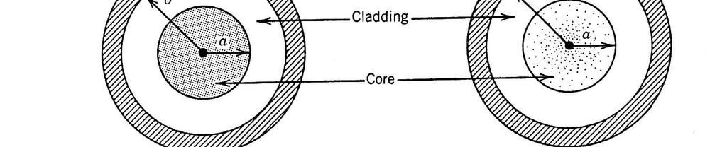
10 Structure of Optical Fiber Coating Clad Core Coating Clad Core Optical Fiber Core Clad Coating Material Germanium doped Silica Glass Pure Silica Glass Acrylate Purpose Guiding the light (High-index region) Supporting the light (Low-index region) Protecting the glass region
11


12
13 Propagation of Light Total internal reflection Input Signal Coating Clad Core Output Signal Light Source Receiver Optical Fiber The signal light is guided within the core of the optical fibe r by the total internal reflection.
14
15 For a fiber with a V nu mber of 4.367, it can support 4 modes as illustrated by the graph V- number Vs propagation constant (Fig 7). Fig 7: V-number Vs Propagation constant ( _) The modes allowed are shown in figure below ( Fig 8). Fig 8: Modes in a slightly multi mode fiber Srikrishna Bhashyam,
16 Modal Dispersion
17 Modal Dispersion
18
19
20 Graded-Index Fiber
21
22 Fiber Attenuation
23

24 Harnessing Optical Fiber Bandwidth C L
25 Power Budget Length = = Plaser " Pdec " PowerPenalty " Potherloss Fiber _ Loss "7dBm " ("35dBm) "10dB 0.2dB /km = 90km! Low insertion loss is very important for all the components along the link.! Power penalty = increase of minimum receiver power for a given SNR (bit error rate) due to the components in the comm. Channel! Caused by dispersion, fiber nonlinearity, etc.! Other power loss: due to multiplexer, connectors, etc.
26 Power Budget Length = P laser! P dec! PowerPenalty Fiber _ Loss! P otherloss =! 7dBm! (! 35dBm) 0.2dB / km! 10dB = 90km! Low insertion loss is very important for all the components along the link.! Power penalty = increase of minimum receiver power for a given SNR (bit error rate) due to the components in the comm. Channel! Caused by dispersion, fiber nonlinearity, etc.! Other power loss: due to multiplexer, connectors, etc.
27 Topics of Interest Fundamental limitations Distance Bandwidth Wavelength range Crosstalk Noise Distance Loss-limit Dispersion-limit Bit rate
28 Fiber Manufacture
29 Geometry of Preform vs. SMF 1/2 After drawing Core diameter of Fiber ~ 9 µm Clad diameter of Preform ~ 80mm Clad diameter of Fiber ~ 125 µm Core diameter of Preform ~ 5.8mm Core Coating diameter ~ 250 µm Clad Coating Clad Core Clad Core Cross-section of Preform Cross-section of Fiber
30 Manufacturing of Optical Fiber Growth of preform with specific doping and index profile
 22mm")
 Moving Core rod 2 nd Pure Silica glass tube")
31 Preform Fabrication (MCVD & OJ processes) 36mm 1 st Pure Silica glass tube 27mm Traveling Deposition MCVD Machine (Modified Chemical Vapor Deposition) 22mm Moving Collapsing & Closing (Core rod) 80mm OJ tube Core rod Core Round torch Clad OJ Machine (Over Jacketing) Moving Core rod 2 nd Pure Silica glass tube Preform
32 Other Manufacturing Processes of Optical Fiber Preform OVD (Outside Vapor Deposition) Deposition VAD (Vapor Axial Deposition) Deposition Seed rod Porous Core (Germanium doped region) Moving Seed rod Traveling Vapors inlet Porous Preform Porous Clad (Pure Silica region) Core soot Clad soot Clad deposition burner Traveling Vapors inlet Core deposition burner Vapors inlet
33 Fiber Drawing (Draw Tower) Preform Furnace (2200~2300 C) Preform diameter : larger than 80 mm Drawing temperature : 2200~2300 C Fiber diameter measurement Cooler Coater UV lamp Fiber diameter : 125 µm Coated fiber diameter : 245 µm Drawing speed : 1200~2100 m/min Fiber length / preform : 360 km Coated fiber diameter measurement Capstan Fiber take-up
34 Manufacturing of Optical Fiber Pulling the fiber from a given preform
35
36 Optical Fiber Typical Dimension for Silica Fibers: SMF: 8 um core, 125 um cladding MMF: 50, 62.5, 100 um core, 125 um cladding Index profile: Step vs. Graded vs. multi-step
37
38
39 Dispersion Different components of transmitted signal travel at different velocities in the fiber and arrive at different times at the receiver Modal dispersion: different modal components of a pulse travel at different velocities Chromatic dispersion: different spectral components of a pulse travel at different velocities Material dispersion: due to!-dependence in doped silica (or any other core material) Waveguide dispersion: due to waveguide design Polarization dispersion: different polarization components of a pulse travel at different velocities
40 Single Mode Fiber Define group velocity dispersion (GVD) parameter " 2 and Dispersion parameter D Intersymbol interference (ISI): pulse broadening effect of chromatic dispersion causes the signal of adjacent bit periods to overlap " Cause power penalty W M g g D D c v d d D d d DL L c v d d L d dt T + = =! " " # $ % % & ' = = ( = ( =! ( " " # $ % % & ' = ( = ( ) * + *, ) ) * * ) * + * * * *
41 Origin of Dispersion and Nonlinearities
42 Polarization Mode Dispersion
43 Geometry of Preform vs. SMF 2/2 Cross-section of Preform Perfect circle of Preform After Drawing Cross-section of Fiber Perfect circle of fiber Non-circular core of Preform Non-circular core of Fiber Non-circular clad of Preform Non-circular clad of Fiber

44
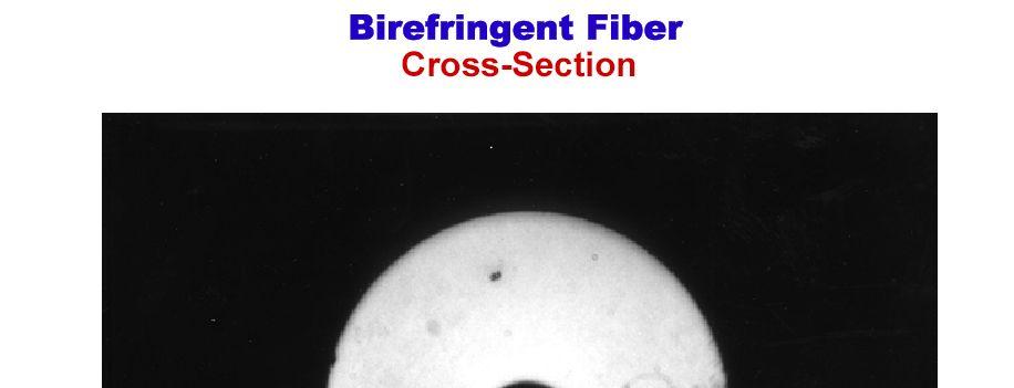
45 Origins of PMD in single-mode fiber (SMF) Intrinsic birefringence Ideal Oval Core Slow axis Form birefringence, characteristic of a non-circular waveguide. Stress birefringence, due to forces acting on a non-circular core. For simple birefringence, fiber PMD is proportional to length. In practice, mode coupling destroys this simple relationship.
46
47
48
49
50 POINCARE SPHERE FROM KRAUS AND FLEISCH
51
52 Origin of Dispersion and Nonlinearities
53 Chromatic Dispersion
54 Group Velocity # / p, N = "! N! ( # ) 1 $ = d" g, N d N /
55 Ramo, Whinnery & Van Duzer
56
57
58
59
60
61
62
63
64
65 Types of dispersion in optical fiber Optical frequencies # 1 # 2 Chromatic dispersion Dispersion in Polarization-mode dispersion pulse Polarization modes arrival times Input pulse Output pulse
66 Chromatic dispersion can be fully compensated Transmission Compensation Input bits Output bits Into receiver Standard fiber: fiber: Dispersion= ps/nmkm Maximum length length without compensation ~ 1/(D 1/(D x Bitrate Bitrate 2 2 )) For For Gb/s Gb/s => => 1000km, for for Gb/s=> km km Methods of of compensation: Fiber Fiber with with inverse dispersion Dispersive filters filters Problems with with compensation: Needs Needs to to be be engineered for for each each link link varies varies with with wavelength (( ~ 1ps/nm 2 2 km) km)

67 Dispersion Engineering For single mode fiber, chromatic dispersion is the dominant dispersion factor
68 Dispersion Engineering

69

70 (Std SMF) (NZDS Fiber) TrueWave Fiber: Conceived in 1992 Commercially available in 1993 TLI: Dec
71
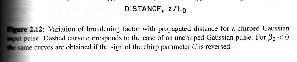
72 Dispersion Management Technique Dispersion-compensating fiber TX RX Transmission fiber Total accumulated dispersion, ps/nm Distance, km Accumulated dispersion at the receiver is close to zero ofcshortcourse.ts.degradation_effects.12
73 FIBER DISPERSION Profile control allows crafting of fiber dispersion Nominal Disp. (ps/nm/km) C-Band Wavelength (nm) L-Band USF Large Area TrueWave+ Reduced Slope DSF SMF-LS
74
75
76
77
78
79 Nonlinear Index Impairments n = n 0 + n 2 (P/A eff ) SPM = self-phase modulation XPM = cross-phase modulation FWM = four-wave mixing
80
81

82 Self and Cross Phase Modulation


83
84 Four Wave Mixing
85
86

87 TLI: Dec
88 Stimulated Raman Scattering and Stimulated Brillouin Scattering
89 Spontaneous and stimulated emission! Einstein!s principle of spontaneous and stimulated emission in LASER media Energy pump absorption fast decay fast decay slow decay phonon phonon 2 1 atomic levels noise photon sustained pumping instant decay signal photon emission atom random noise photon OUT spontaneous emission signal photon signal photons IN OUT stimulated emission Desurvire -Campinas
90 Spontaneous and stimulated scattering! Spontaneous and stimulated scattering are similar processes spontaneous (single) pump photon absorption instant decay fast decay phonon 2 noise photon 1 virtual level sustained pump photon absorption instant decay signal photon emission molecule random noise photon OUT spontaneous scattering signal photon IN stimulated scattering signal photons OUT Desurvire -Campinas
91 Spontaneous/stimulated emission vs. scattering! Both generate (spontaneous) noise photons and (stimulated) coherent signal photons. More to come next.! Both processes act as laser systems, the first with rare-earth ions as fiber dopants (e.g. erbium, tullium, praseodymium), the second with molecules forming the glass fiber host (e.g. Si-O-Si, or P-O-P), with is the Raman effect.! Both stimulated-emission processes (RE doping and Raman) clone input signal photons (same output polarization and phase); the avalanche effect generates coherent signal wave with power amplified by gain factors between 10 and 10 4 (10dB to 40dB)! With RE-doped amplifiers, the energy levels are fixed, thus determining fixed pump (absorption) and fixed signal (emission) bands; with Raman amplifiers, only the frequency difference between pump and signal is fixed, making the signal band tunable. DesurvireCampinas
92
93
94 The End
95
Guided Propagation Along the Optical Fiber. Xavier Fernando Ryerson Comm. Lab
 Guided Propagation Along the Optical Fiber Xavier Fernando Ryerson Comm. Lab The Nature of Light Quantum Theory Light consists of small particles (photons) Wave Theory Light travels as a transverse electromagnetic
The absorption of the light may be intrinsic or extrinsic
 Attenuation Fiber Attenuation Types 1- Material Absorption losses 2- Intrinsic Absorption 3- Extrinsic Absorption 4- Scattering losses (Linear and nonlinear) 5- Bending Losses (Micro & Macro) Material
Fiber Amplifiers. Fiber Lasers. 1*5 World Scientific. Niloy K nulla. University ofconnecticut, USA HONG KONG NEW JERSEY LONDON
 LONDON Fiber Amplifiers Fiber Lasers Niloy K nulla University ofconnecticut, USA 1*5 World Scientific NEW JERSEY SINGAPORE BEIJING SHANGHAI HONG KONG TAIPEI CHENNAI Contents Preface v 1. Introduction 1
Optical Amplifiers Photonics and Integrated Optics (ELEC-E3240) Zhipei Sun Photonics Group Department of Micro- and Nanosciences Aalto University
 Zhipei Sun Photonics Group Department of Micro- and Nanosciences Aalto University") Photonics Group Department of Micro- and Nanosciences Aalto University Optical Amplifiers Photonics and Integrated Optics (ELEC-E3240) Zhipei Sun Last Lecture Topics Course introduction Ray optics & optical
Photonics Group Department of Micro- and Nanosciences Aalto University Optical Amplifiers Photonics and Integrated Optics (ELEC-E3240) Zhipei Sun Last Lecture Topics Course introduction Ray optics & optical
Performance Analysis of Designing a Hybrid Optical Amplifier (HOA) for 32 DWDM Channels in L-band by using EDFA and Raman Amplifier
 for 32 DWDM Channels in L-band by using EDFA and Raman Amplifier") Performance Analysis of Designing a Hybrid Optical Amplifier (HOA) for 32 DWDM Channels in L-band by using EDFA and Raman Amplifier Aied K. Mohammed, PhD Department of Electrical Engineering, University
Performance Analysis of Designing a Hybrid Optical Amplifier (HOA) for 32 DWDM Channels in L-band by using EDFA and Raman Amplifier Aied K. Mohammed, PhD Department of Electrical Engineering, University
UNIT-II : SIGNAL DEGRADATION IN OPTICAL FIBERS
 UNIT-II : SIGNAL DEGRADATION IN OPTICAL FIBERS The Signal Transmitting through the fiber is degraded by two mechanisms. i) Attenuation ii) Dispersion Both are important to determine the transmission characteristics
DIELECTRIC WAVEGUIDES and OPTICAL FIBERS
 DIELECTRIC WAVEGUIDES and OPTICAL FIBERS Light Light Light n 2 n 2 Light n 1 > n 2 A planar dielectric waveguide has a central rectangular region of higher refractive index n 1 than the surrounding region
Guided Propagation Along the Optical Fiber. Xavier Fernando Ryerson University
 Guided Propagation Along the Optical Fiber Xavier Fernando Ryerson University The Nature of Light Quantum Theory Light consists of small particles (photons) Wave Theory Light travels as a transverse electromagnetic
Optical Fiber Technology. Photonic Network By Dr. M H Zaidi
 Optical Fiber Technology Numerical Aperture (NA) What is numerical aperture (NA)? Numerical aperture is the measure of the light gathering ability of optical fiber The higher the NA, the larger the core
Dr. Monir Hossen ECE, KUET
 Dr. Monir Hossen ECE, KUET 1 Outlines of the Class Principles of WDM DWDM, CWDM, Bidirectional WDM Components of WDM AWG, filter Problems with WDM Four-wave mixing Stimulated Brillouin scattering WDM Network
τ mod = T modal = longest ray path shortest ray path n 1 L 1 = L n 2 1
 S. Blair February 15, 2012 23 2.2. Pulse dispersion Pulse dispersion is the spreading of a pulse as it propagates down an optical fiber. Pulse spreading is an obvious detrimental effect that limits the
Types of losses in optical fiber cable are: Due to attenuation, the power of light wave decreases exponentially with distance.
 UNIT-II TRANSMISSION CHARACTERISTICS OF OPTICAL FIBERS SIGNAL ATTENUATION: Signal attenuation in an optical fiber is defined as the decrease in light power during light propagation along an optical fiber.
Guided Propagation Along the Optical Fiber
 Guided Propagation Along the Optical Fiber The Nature of Light Quantum Theory Light consists of small particles (photons) Wave Theory Light travels as a transverse electromagnetic wave Ray Theory Light
Total care for networks. Introduction to Dispersion
 Introduction to Dispersion Introduction to PMD Version1.0- June 01, 2000 Copyright GN Nettest 2000 Introduction To Dispersion Contents Definition of Dispersion Chromatic Dispersion Polarization Mode Dispersion
OPTI510R: Photonics. Khanh Kieu College of Optical Sciences, University of Arizona Meinel building R.626
 OPTI510R: Photonics Khanh Kieu College of Optical Sciences, University of Arizona kkieu@optics.arizona.edu Meinel building R.626 Announcements HW #5 is assigned (due April 9) April 9 th class will be in
Optical Transport Tutorial
 Optical Transport Tutorial 4 February 2015 2015 OpticalCloudInfra Proprietary 1 Content Optical Transport Basics Assessment of Optical Communication Quality Bit Error Rate and Q Factor Wavelength Division
Impact of Fiber Non-Linearities in Performance of Optical Communication
 Impact of Fiber Non-Linearities in Performance of Optical Communication Narender Kumar Sihval 1, Vivek Kumar Malik 2 M. Tech Students in ECE Department, DCRUST-Murthal, Sonipat, India Abstract: Non-linearity
Performance Evaluation of 32 Channel DWDM System Using Dispersion Compensation Unit at Different Bit Rates
 Performance Evaluation of 32 Channel DWDM System Using Dispersion Compensation Unit at Different Bit Rates Simarpreet Kaur Gill 1, Gurinder Kaur 2 1Mtech Student, ECE Department, Rayat- Bahra University,
Optical Fibre Amplifiers Continued
 1 Optical Fibre Amplifiers Continued Stavros Iezekiel Department of Electrical and Computer Engineering University of Cyprus ECE 445 Lecture 09 Fall Semester 2016 2 ERBIUM-DOPED FIBRE AMPLIFIERS BASIC
Signal Conditioning Parameters for OOFDM System
 Chapter 4 Signal Conditioning Parameters for OOFDM System 4.1 Introduction The idea of SDR has been proposed for wireless transmission in 1980. Instead of relying on dedicated hardware, the network has
Chapter 8. Wavelength-Division Multiplexing (WDM) Part II: Amplifiers
 Part II: Amplifiers") Chapter 8 Wavelength-Division Multiplexing (WDM) Part II: Amplifiers Introduction Traditionally, when setting up an optical link, one formulates a power budget and adds repeaters when the path loss exceeds
Chapter 8 Wavelength-Division Multiplexing (WDM) Part II: Amplifiers Introduction Traditionally, when setting up an optical link, one formulates a power budget and adds repeaters when the path loss exceeds
Chapter 12: Optical Amplifiers: Erbium Doped Fiber Amplifiers (EDFAs)
") Chapter 12: Optical Amplifiers: Erbium Doped Fiber Amplifiers (EDFAs) Prof. Dr. Yaocheng SHI ( 时尧成 ) yaocheng@zju.edu.cn http://mypage.zju.edu.cn/yaocheng 1 Traditional Optical Communication System Loss
Chapter 12: Optical Amplifiers: Erbium Doped Fiber Amplifiers (EDFAs) Prof. Dr. Yaocheng SHI ( 时尧成 ) yaocheng@zju.edu.cn http://mypage.zju.edu.cn/yaocheng 1 Traditional Optical Communication System Loss
High Performance Dispersion and Dispersion Slope Compensating Fiber Modules for Non-zero Dispersion Shifted Fibers
 High Performance Dispersion and Dispersion Slope Compensating Fiber Modules for Non-zero Dispersion Shifted Fibers Kazuhiko Aikawa, Ryuji Suzuki, Shogo Shimizu, Kazunari Suzuki, Masato Kenmotsu, Masakazu
Analysis of Self Phase Modulation Fiber nonlinearity in Optical Transmission System with Dispersion
 36 Analysis of Self Phase Modulation Fiber nonlinearity in Optical Transmission System with Dispersion Supreet Singh 1, Kulwinder Singh 2 1 Department of Electronics and Communication Engineering, Punjabi
Elements of Optical Networking
 Bruckner Elements of Optical Networking Basics and practice of optical data communication With 217 Figures, 13 Tables and 93 Exercises Translated by Patricia Joliet VIEWEG+ TEUBNER VII Content Preface
ANALYSIS OF DISPERSION COMPENSATION IN A SINGLE MODE OPTICAL FIBER COMMUNICATION SYSTEM
 ANAYSIS OF DISPERSION COMPENSATION IN A SINGE MODE OPTICA FIBER COMMUNICATION SYSTEM Sani Abdullahi Mohammed 1, Engr. Yahya Adamu and Engr. Matthew Kwatri uka 3 1,,3 Department of Electrical and Electronics
Photonics and Optical Communication Spring 2005
 Photonics and Optical Communication Spring 2005 Final Exam Instructor: Dr. Dietmar Knipp, Assistant Professor of Electrical Engineering Name: Mat. -Nr.: Guidelines: Duration of the Final Exam: 2 hour You
8 10 Gbps optical system with DCF and EDFA for different channel spacing
 Research Article International Journal of Advanced Computer Research, Vol 6(24) ISSN (Print): 2249-7277 ISSN (Online): 2277-7970 http://dx.doi.org/10.19101/ijacr.2016.624002 8 10 Gbps optical system with
Dispersion Measurements of High-Speed Lightwave Systems
 Lightwave Symposium Dispersion Measurements of Presented by Johann L. Fernando, Product Manager 3-1 Topics Chromatic dispersion concepts Agilent 86037C Chromatic Dispersion Measurement System Polarization
Optical systems have carrier frequencies of ~100 THz. This corresponds to wavelengths from µm.
 Introduction A communication system transmits information form one place to another. This could be from one building to another or across the ocean(s). Many systems use an EM carrier wave to transmit information.
Unit-5. Lecture -4. Power Penalties,
 Unit-5 Lecture -4 Power Penalties, Power Penalties When any signal impairments are present, a lower optical power level arrives at the receiver compared to the ideal reception case. This lower power results
Fiber-Optic Communication Systems
 Fiber-Optic Communication Systems Second Edition GOVIND P. AGRAWAL The Institute of Optics University of Rochester Rochester, NY A WILEY-iNTERSCIENCE PUBLICATION JOHN WILEY & SONS, INC. NEW YORK / CHICHESTER
Lecture 3 Fiber Optical Communication Lecture 3, Slide 1
 Lecture 3 Dispersion in single-mode fibers Material dispersion Waveguide dispersion Limitations from dispersion Propagation equations Gaussian pulse broadening Bit-rate limitations Fiber losses Fiber Optical
DWDM Theory. ZTE Corporation Transmission Course Team. ZTE University
 DWDM Theory ZTE Corporation Transmission Course Team DWDM Overview Multiplexing Technology WDM TDM SDM What is DWDM? Gas Station High Way Prowl Car Definition l 1 l 2 l N l 1 l 2 l 1 l 2 l N OA l N OMU
Chapter 2: Fiber Optics as a communication medium
 Chapter 2: Fiber Optics as a communication medium 2.1 Fiber Fabrication: Basically, fiber manufacturers use two methods to fabricate multimode and single mode glass fibers. One method is vapor phase oxidation,
Section B Lecture 5 FIBER CHARACTERISTICS
 Section B Lecture 5 FIBER CHARACTERISTICS Material absorption Losses Material absorption is a loss mechanism related to material composition and fabrication process for the fiber. This results in dissipation
Analyzing the Non-Linear Effects in DWDM Optical Network Using MDRZ Modulation Format
 Analyzing the Non-Linear Effects in DWDM Optical Network Using MDRZ Modulation Format Ami R. Lavingia Electronics & Communication Dept. SAL Institute of Technology & Engineering Research Gujarat Technological
DISPERSION COMPENSATING FIBER
 DISPERSION COMPENSATING FIBER Dispersion-Compensating SM Fiber for Telecom Wavelengths (1520-1625 nm) DCF38 is Specifically Designed to Compensate Corning SMF-28e+ Fiber Short Pulse Broad Pulse due to
Mixing TrueWave RS Fiber with Other Single-Mode Fiber Designs Within a Network
 Mixing TrueWave RS Fiber with Other Single-Mode Fiber Designs Within a Network INTRODUCTION A variety of single-mode fiber types can be found in today s installed networks. Standards bodies, such as the
Advanced Fibre Testing: Paving the Way for High-Speed Networks. Trevor Nord Application Specialist JDSU (UK) Ltd
 Ltd") Advanced Fibre Testing: Paving the Way for High-Speed Networks Trevor Nord Application Specialist JDSU (UK) Ltd Fibre Review Singlemode Optical Fibre Elements of Loss Fibre Attenuation - Caused by scattering
Advanced Fibre Testing: Paving the Way for High-Speed Networks Trevor Nord Application Specialist JDSU (UK) Ltd Fibre Review Singlemode Optical Fibre Elements of Loss Fibre Attenuation - Caused by scattering
Lecture 10. Dielectric Waveguides and Optical Fibers
 Lecture 10 Dielectric Waveguides and Optical Fibers Slab Waveguide, Modes, V-Number Modal, Material, and Waveguide Dispersions Step-Index Fiber, Multimode and Single Mode Fibers Numerical Aperture, Coupling
MAHALAKSHMI ENGINEERING COLLEGE TIRUCHIRAPALLI
 MAHALAKSHMI ENGINEERING COLLEGE TIRUCHIRAPALLI - 621213 DEPARTMENT : ECE SUBJECT NAME : OPTICAL COMMUNICATION & NETWORKS SUBJECT CODE : EC 2402 UNIT II: TRANSMISSION CHARACTERISTICS OF OPTICAL FIBERS PART
Optical Communications and Networking 朱祖勍. Oct. 9, 2017
 Optical Communications and Networking Oct. 9, 2017 1 Optical Amplifiers In optical communication systems, the optical signal from the transmitter are attenuated by the fiber and other passive components
Performance Limitations of WDM Optical Transmission System Due to Cross-Phase Modulation in Presence of Chromatic Dispersion
 Performance Limitations of WDM Optical Transmission System Due to Cross-Phase Modulation in Presence of Chromatic Dispersion M. A. Khayer Azad and M. S. Islam Institute of Information and Communication
Available online at ScienceDirect. Procedia Computer Science 93 (2016 )
") Available online at www.sciencedirect.com ScienceDirect Procedia Computer Science 93 (016 ) 647 654 6th International Conference On Advances In Computing & Communications, ICACC 016, 6-8 September 016,
Available online at www.sciencedirect.com ScienceDirect Procedia Computer Science 93 (016 ) 647 654 6th International Conference On Advances In Computing & Communications, ICACC 016, 6-8 September 016,
Optical Digital Transmission Systems. Xavier Fernando ADROIT Lab Ryerson University
 Optical Digital Transmission Systems Xavier Fernando ADROIT Lab Ryerson University Overview In this section we cover point-to-point digital transmission link design issues (Ch8): Link power budget calculations
Enabling technology for suppressing nonlinear interchannel crosstalk in DWDM transoceanic systems
 1/13 Enabling technology for suppressing nonlinear interchannel crosstalk in DWDM transoceanic systems H. Zhang R.B. Jander C. Davidson D. Kovsh, L. Liu A. Pilipetskii and N. Bergano April 2005 1/12 Main
International Journal Of Scientific Research And Education Volume 3 Issue 4 Pages April-2015 ISSN (e): Website:
: Website:") International Journal Of Scientific Research And Education Volume 3 Issue 4 Pages-3183-3188 April-2015 ISSN (e): 2321-7545 Website: http://ijsae.in Effects of Four Wave Mixing (FWM) on Optical Fiber in
International Journal Of Scientific Research And Education Volume 3 Issue 4 Pages-3183-3188 April-2015 ISSN (e): 2321-7545 Website: http://ijsae.in Effects of Four Wave Mixing (FWM) on Optical Fiber in
RZ BASED DISPERSION COMPENSATION TECHNIQUE IN DWDM SYSTEM FOR BROADBAND SPECTRUM
 RZ BASED DISPERSION COMPENSATION TECHNIQUE IN DWDM SYSTEM FOR BROADBAND SPECTRUM Prof. Muthumani 1, Mr. Ayyanar 2 1 Professor and HOD, 2 UG Student, Department of Electronics and Communication Engineering,
FIBER OPTICS. Prof. R.K. Shevgaonkar. Department of Electrical Engineering. Indian Institute of Technology, Bombay. Lecture: 37
 FIBER OPTICS Prof. R.K. Shevgaonkar Department of Electrical Engineering Indian Institute of Technology, Bombay Lecture: 37 Introduction to Raman Amplifiers Fiber Optics, Prof. R.K. Shevgaonkar, Dept.
Practical Aspects of Raman Amplifier
 Practical Aspects of Raman Amplifier Contents Introduction Background Information Common Types of Raman Amplifiers Principle Theory of Raman Gain Noise Sources Related Information Introduction This document
EKT 465 OPTICAL COMMUNICATION SYSTEM. Chapter 2 OPTICAL FIBER COMMUNICATIONS
 EKT 465 OPTICAL COMMUNICATION SYSTEM Chapter 2 OPTICAL FIBER COMMUNICATIONS SEMESTER 1-2017/18 3 Credit Hours 222.3 Gbps pada 2017, daripada 6.4Gbps pada 2012 10/3/2017 2 Light Propagation & Transmission
Passive Fibre Components
 SMR 1829-16 Winter College on Fibre Optics, Fibre Lasers and Sensors 12-23 February 2007 Passive Fibre Components (PART 2) Walter Margulis Acreo, Stockholm Sweden Passive Fibre Components W. Margulis walter.margulis@acreo.se
SIMULATION OF PHOTONIC DEVICES OPTICAL FIBRES
 Journal of Optoelectronics and Advanced Materials Vol. 3, No. 4, December 2001, p. 925-931 SIMULATION OF PHOTONIC DEVICES OPTICAL FIBRES Nortel Networks Montigny Le Bretonneux 6, rue de Viel Etang 78928
Development of Highly Nonlinear Fibers for Optical Signal Processing
 Development of Highly Nonlinear Fibers for Optical Signal Processing by Jiro Hiroishi *, Ryuichi Sugizaki *, Osamu so *2, Masateru Tadakuma *2 and Taeko Shibuta *3 Nonlinear optical phenomena occurring
S Optical Networks Course Lecture 4: Transmission System Engineering
 S-72.3340 Optical Networks Course Lecture 4: Transmission System Engineering Edward Mutafungwa Communications Laboratory, Helsinki University of Technology, P. O. Box 2300, FIN-02015 TKK, Finland Tel:
Chapter 3 Signal Degradation in Optical Fibers
 What about the loss in optical fiber? Why and to what degree do optical signals gets distorted as they propagate along a fiber? Fiber links are limited by in path length by attenuation and pulse distortion.
There are lots of problems or challenges with fiber, Attenuation, Reflections, Dispersion and so on. So here we will look at these problems.
 The Hard theory The Hard Theory An introduction to fiber, should also include a section with some of the difficult theory. So if everything else in the book was very easily understood, then this section
Examination Optoelectronic Communication Technology. April 11, Name: Student ID number: OCT1 1: OCT 2: OCT 3: OCT 4: Total: Grade:
 Examination Optoelectronic Communication Technology April, 26 Name: Student ID number: OCT : OCT 2: OCT 3: OCT 4: Total: Grade: Declaration of Consent I hereby agree to have my exam results published on
Chapter 8. Digital Links
 Chapter 8 Digital Links Point-to-point Links Link Power Budget Rise-time Budget Power Penalties Dispersions Noise Content Photonic Digital Link Analysis & Design Point-to-Point Link Requirement: - Data
Current Trends in Unrepeatered Systems
 Current Trends in Unrepeatered Systems Wayne Pelouch (Xtera, Inc.) Email: wayne.pelouch@xtera.com Xtera, Inc. 500 W. Bethany Drive, suite 100, Allen, TX 75013, USA. Abstract: The current trends in unrepeatered
Fiberoptic Communication Systems By Dr. M H Zaidi. Optical Amplifiers
 Optical Amplifiers Optical Amplifiers Optical signal propagating in fiber suffers attenuation Optical power level of a signal must be periodically conditioned Optical amplifiers are a key component in
Photonics and Optical Communication
 Photonics and Optical Communication (Course Number 300352) Spring 2007 Dr. Dietmar Knipp Assistant Professor of Electrical Engineering http://www.faculty.iu-bremen.de/dknipp/ 1 Photonics and Optical Communication
Optimization of supercontinuum generation in photonic crystal fibers for pulse compression
 Optimization of supercontinuum generation in photonic crystal fibers for pulse compression Noah Chang Herbert Winful,Ted Norris Center for Ultrafast Optical Science University of Michigan What is Photonic
Multi-wavelength laser generation with Bismuthbased Erbium-doped fiber
 Multi-wavelength laser generation with Bismuthbased Erbium-doped fiber H. Ahmad 1, S. Shahi 1 and S. W. Harun 1,2* 1 Photonics Research Center, University of Malaya, 50603 Kuala Lumpur, Malaysia 2 Department
UNIT - 7 WDM CONCEPTS AND COMPONENTS
 UNIT - 7 LECTURE-1 WDM CONCEPTS AND COMPONENTS WDM concepts, overview of WDM operation principles, WDM standards, Mach-Zehender interferometer, multiplexer, Isolators and circulators, direct thin film
Performance of A Multicast DWDM Network Applied to the Yemen Universities Network using Quality Check Algorithm
 Performance of A Multicast DWDM Network Applied to the Yemen Universities Network using Quality Check Algorithm Khaled O. Basulaim, Samah Ali Al-Azani Dept. of Information Technology Faculty of Engineering,
Performance analysis of Erbium Doped Fiber Amplifier at different pumping configurations
 Performance analysis of Erbium Doped Fiber Amplifier at different pumping configurations Mayur Date M.E. Scholar Department of Electronics and Communication Ujjain Engineering College, Ujjain (M.P.) datemayur3@gmail.com
SCTE. San Diego Chapter March 19, 2014
 SCTE San Diego Chapter March 19, 2014 RFOG WHAT IS RFOG? WHY AND WHERE IS THIS TECHNOLOGY A CONSIDERATION? RFoG could be considered the deepest fiber version of HFC RFoG pushes fiber to the side of the
OPTI510R: Photonics. Khanh Kieu College of Optical Sciences, University of Arizona Meinel building R.626
 OPTI510R: Photonics Khanh Kieu College of Optical Sciences, University of Arizona kkieu@optics.arizona.edu Meinel building R.626 Announcements Homework #4 is due today, HW #5 is assigned (due April 8)
Photonics (OPTI 510R 2017) - Final exam. (May 8, 10:30am-12:30pm, R307)
 - Final exam. (May 8, 10:30am-12:30pm, R307)") Photonics (OPTI 510R 2017) - Final exam (May 8, 10:30am-12:30pm, R307) Problem 1: (30pts) You are tasked with building a high speed fiber communication link between San Francisco and Tokyo (Japan) which
Photonics (OPTI 510R 2017) - Final exam (May 8, 10:30am-12:30pm, R307) Problem 1: (30pts) You are tasked with building a high speed fiber communication link between San Francisco and Tokyo (Japan) which
Lecture 8 Fiber Optical Communication Lecture 8, Slide 1
 Lecture 8 Bit error rate The Q value Receiver sensitivity Sensitivity degradation Extinction ratio RIN Timing jitter Chirp Forward error correction Fiber Optical Communication Lecture 8, Slide Bit error
Bragg and fiber gratings. Mikko Saarinen
 Bragg and fiber gratings Mikko Saarinen 27.10.2009 Bragg grating - Bragg gratings are periodic perturbations in the propagating medium, usually periodic variation of the refractive index - like diffraction
Chapter 9 GUIDED WAVE OPTICS
 [Reading Assignment, Hecht 5.6] Chapter 9 GUIDED WAVE OPTICS Optical fibers The step index circular waveguide is the most common fiber design for optical communications plastic coating (sheath) core cladding
CONTENTS. Chapter 1 Wave Nature of Light 19
 CONTENTS Chapter 1 Wave Nature of Light 19 1.1 Light Waves in a Homogeneous Medium 19 A. Plane Electromagnetic Wave 19 B. Maxwell's Wave Equation and Diverging Waves 22 Example 1.1.1 A diverging laser
Optimisation of DSF and SOA based Phase Conjugators. by Incorporating Noise-Suppressing Fibre Gratings
 Optimisation of DSF and SOA based Phase Conjugators by Incorporating Noise-Suppressing Fibre Gratings Paper no: 1471 S. Y. Set, H. Geiger, R. I. Laming, M. J. Cole and L. Reekie Optoelectronics Research
Emerging Subsea Networks
 EVALUATION OF NONLINEAR IMPAIRMENT FROM NARROW- BAND UNPOLARIZED IDLERS IN COHERENT TRANSMISSION ON DISPERSION-MANAGED SUBMARINE CABLE SYSTEMS Masashi Binkai, Keisuke Matsuda, Tsuyoshi Yoshida, Naoki Suzuki,
Optical Fiber Amplifiers
 Optical Fiber Amplifiers Yousif Ahmed Omer 1 and Dr. Hala Eldaw Idris 2 1,2 Department of communication Faculty of Engineering, AL-Neelain University, Khartoum, Sudan Publishing Date: June 15, 2016 Abstract
Introduction Fundamental of optical amplifiers Types of optical amplifiers
 ECE 6323 Introduction Fundamental of optical amplifiers Types of optical amplifiers Erbium-doped fiber amplifiers Semiconductor optical amplifier Others: stimulated Raman, optical parametric Advanced application:
OPTICAL NETWORKS. Building Blocks. A. Gençata İTÜ, Dept. Computer Engineering 2005
 OPTICAL NETWORKS Building Blocks A. Gençata İTÜ, Dept. Computer Engineering 2005 Introduction An introduction to WDM devices. optical fiber optical couplers optical receivers optical filters optical amplifiers
Four wave mixing and parametric amplification in Si-nano waveguides using reverse biased pnjunctions
 Four wave mixing and parametric amplification in Si-nano waveguides using reverse biased pnjunctions for carrier removal E-Mail: petermann@tu-berlin.de Acknowledgements A.Gajda 1, G.Winzer 1, L.Zimmermann
2 in the multipath dispersion of the optical fibre. (b) Discuss the merits and drawbacks of cut bouls method of measurement of alternation.
 Discuss the merits and drawbacks of cut bouls method of measurement of alternation.") B.TECH IV Year I Semester (R09) Regular Examinations, November 2012 1 (a) Derive an expression for multiple time difference tt 2 in the multipath dispersion of the optical fibre. (b) Discuss the merits
B.TECH IV Year I Semester (R09) Regular Examinations, November 2012 1 (a) Derive an expression for multiple time difference tt 2 in the multipath dispersion of the optical fibre. (b) Discuss the merits
DESIGN TEMPLATE ISSUES ANALYSIS FOR ROBUST DESIGN OUTPUT. performance, yield, reliability
 DESIGN TEMPLATE ISSUES performance, yield, reliability ANALYSIS FOR ROBUST DESIGN properties, figure-of-merit thermodynamics, kinetics, process margins process control OUTPUT models, options Optical Amplification
Performance Analysis Of Hybrid Optical OFDM System With High Order Dispersion Compensation
 Performance Analysis Of Hybrid Optical OFDM System With High Order Dispersion Compensation Manpreet Singh Student, University College of Engineering, Punjabi University, Patiala, India. Abstract Orthogonal
UNIT List the requirements that be satisfied by materials used to manufacture optical fiber? ANS: Fiber Materials
 UNIT- 2 1. List the requirements that be satisfied by materials used to manufacture optical fiber? ANS: Fiber Materials Most of the fibers are made up of glass consisting of either Silica (SiO 2 ) or.silicate.
Polarization Mode Dispersion compensation in WDM system using dispersion compensating fibre
 Polarization Mode Dispersion compensation in WDM system using dispersion compensating fibre AMANDEEP KAUR (Assist. Prof.) ECE department GIMET Amritsar Abstract: In this paper, the polarization mode dispersion
SPECIFICATION. FOR SINGLE-MODE OPTICAL FIBER (FutureGuide -SR15E)
") Fujikura DATE Aug. 18, 2008 NO. JFS-00052A Supersedes JFS-00052 Messrs. SPECIFICATION FOR SINGLE-MODE OPTICAL FIBER (FutureGuide -SR15E) Prepared by H. KIKUCHI Manager Optical Fiber and Cable Dept. Global
Fujikura DATE Aug. 18, 2008 NO. JFS-00052A Supersedes JFS-00052 Messrs. SPECIFICATION FOR SINGLE-MODE OPTICAL FIBER (FutureGuide -SR15E) Prepared by H. KIKUCHI Manager Optical Fiber and Cable Dept. Global
UNIT I INTRODUCTION TO OPTICAL FIBERS
 UNIT I INTRODUCTION TO OPTICAL FIBERS 9 Evolution of fiber optic system Element of an Optical Fiber Transmission link Total internal reflection Acceptance angle Numerical aperture Skew rays Ray Optics
Nonlinear Effect of Four Wave Mixing for WDM in Radio-over-Fiber Systems
 Quest Journals Journal of Electronics and Communication Engineering Research Volume ~ Issue 4 (014) pp: 01-06 ISSN(Online) : 31-5941 www.questjournals.org Research Paper Nonlinear Effect of Four Wave Mixing
ABSTRACT NONLINEAR EQUALIZATION BASED ON DECISION FEEDBACK EQUALIZER FOR OPTICAL COMMUNICATION SYSTEM. by Xiaoqi Han
 ABSTRACT NONLINEAR EQUALIZATION BASED ON DECISION FEEDBACK EQUALIZER FOR OPTICAL COMMUNICATION SYSTEM by Xiaoqi Han Nonlinear impairments in optical communication systems have become the major performance
Fundamentals of Electromagnetics With Engineering Applications by Stuart M. Wentworth Copyright 2005 by John Wiley & Sons. All rights reserved.
 Figure 7-1 (p. 339) Non-TEM mmode waveguide structures include (a) rectangular waveguide, (b) circular waveguide., (c) dielectric slab waveguide, and (d) fiber optic waveguide. Figure 7-2 (p. 340) Cross
Network Challenges for Coherent Systems. Mike Harrop Technical Sales Engineering, EXFO
 Network Challenges for Coherent Systems Mike Harrop Technical Sales Engineering, EXFO Agenda 1. 100G Transmission Technology 2. Non Linear effects 3. RAMAN Amplification 1. Optimsing gain 2. Keeping It
NEW YORK CITY COLLEGE of TECHNOLOGY
 NEW YORK CITY COLLEGE of TECHNOLOGY THE CITY UNIVERSITY OF NEW YORK DEPARTMENT OF ELECTRICAL AND TELECOMMUNICATIONS ENGINEERING TECHNOLOGY Course : Prepared by: TCET 4102 Fiber-optic communications Module
CHAPTER 1 INTRODUCTION
 1 CHAPTER 1 INTRODUCTION 1.1 MOTIVATION With the ever-expanding growth of Internet traffic, we are witnessing a new era in telecommunications. This era was ushered when data traffic began to exceed the
EC Optical Communication And Networking TWO MARKS QUESTION AND ANSWERS UNIT -1 INTRODUCTION
 EC6702 - Optical Communication And Networking TWO MARKS QUESTION AND ANSWERS UNIT -1 INTRODUCTION Ray Theory Transmission 1. Write short notes on ray optics theory. Laws governing the nature of light are
Faculty of Science, Art and Heritage, Universiti Tun Hussein Onn Malaysia, Batu Pahat, Johor, Malaysia.
 An All-Optical Frequency Up/Down-Converter Utilizing Stimulated Brillouin Scattering In A Trf And Dcf For Rof Application N. A. Awang 1,2, H. Ahmad 2, S. F. Norizan 2, M.Z. Zulkifli 2, Z.A.Ghani 4 and
Fiber Optic Communications Communication Systems
 INTRODUCTION TO FIBER-OPTIC COMMUNICATIONS A fiber-optic system is similar to the copper wire system in many respects. The difference is that fiber-optics use light pulses to transmit information down
Fiber Optic Principles. Oct-09 1
 Fiber Optic Principles Oct-09 1 Fiber Optic Basics Optical fiber Active components Attenuation Power budget Bandwidth Oct-09 2 Reference www.flukenetworks.com/fiber Handbook Fiber Optic Technologies (Vivec
Optical Communications and Networking 朱祖勍. Sept. 25, 2017
 Optical Communications and Networking Sept. 25, 2017 Lecture 4: Signal Propagation in Fiber 1 Nonlinear Effects The assumption of linearity may not always be valid. Nonlinear effects are all related to
Dispersion in Optical Fibers
 Dispersion in Optical Fibers By Gildas Chauvel Anritsu Corporation TABLE OF CONTENTS Introduction Chromatic Dispersion (CD): Definition and Origin; Limit and Compensation; and Measurement Methods Polarization