Lecture 10. Dielectric Waveguides and Optical Fibers
|
|
|
- Kory Hodge
- 6 years ago
- Views:
Transcription
1 Lecture 10 Dielectric Waveguides and Optical Fibers Slab Waveguide, Modes, V-Number Modal, Material, and Waveguide Dispersions Step-Index Fiber, Multimode and Single Mode Fibers Numerical Aperture, Coupling Loss Bit-Rate, dispersion and optical bandwidth Graded-index fibers Absorption and Scattering
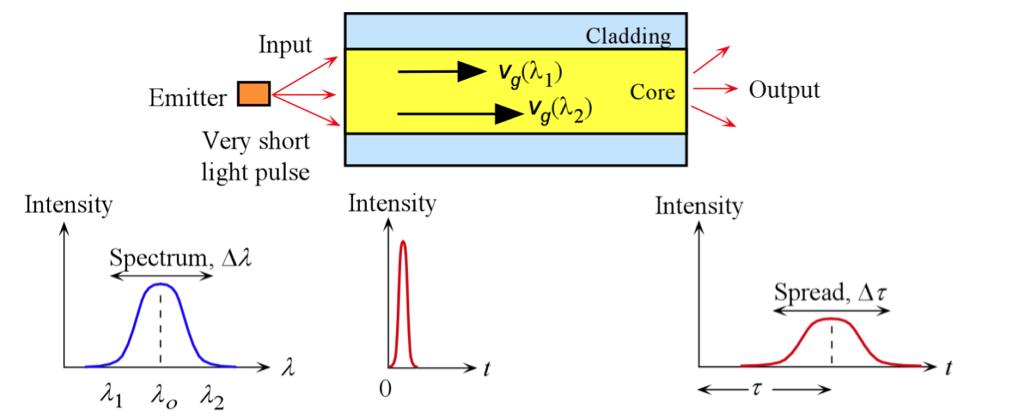
2 Dispersion! Intermode (Intermodal) Dispersion: Multimode fibers only! Materials Dispersion Group velocity depends on N g and hence on λ! Waveguide Dispersion Group velocity depends on waveguide structure! Chromatic Dispersion Material dispersion + Waveguide Dispersion! Profile Dispersion! Polarization Dispersion Intramodal Dispersion
3 Dispersion! Intermode (Intermodal) Dispersion: Multimode fibers only! Materials Dispersion Group velocity depends on N g and hence on λ! Waveguide Dispersion Group velocity depends on waveguide structure! Chromatic Dispersion Material dispersion + Waveguide Dispersion! Profile Dispersion! Polarization Dispersion
4 Intermode Dispersion (MMF)
5 Dispersion! Intermode (Intermodal) Dispersion: Multimode fibers only! Materials Dispersion Group velocity depends on N g and hence on λ! Waveguide Dispersion Group velocity depends on waveguide structure! Chromatic Dispersion Material dispersion + Waveguide Dispersion! Profile Dispersion! Polarization Dispersion
 Group")
6 Material Dispersion (SMF) Group Velocity
7 Material Dispersion (SMF)
8 Material Dispersion (SMF)
9 Dispersion! Intermode (Intermodal) Dispersion: Multimode fibers only! Materials Dispersion Group velocity depends on N g and hence on λ! Waveguide Dispersion Group velocity depends on waveguide structure! Chromatic Dispersion Material dispersion + Waveguide Dispersion! Profile Dispersion! Polarization Dispersion
10 Waveguide Dispersion (SMF) Wavelength Dependent!!
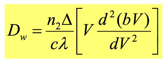
11 Waveguide Dispersion (SMF)
12 Intramodal Dispersions (SMF)
13 Chromatic Dispersion (SMF)
14 Dispersion! Intermode (Intermodal) Dispersion: Multimode fibers only! Materials Dispersion Group velocity depends on N g and hence on λ! Waveguide Dispersion Group velocity depends on waveguide structure! Chromatic Dispersion Material dispersion + Waveguide Dispersion! Profile Dispersion! Polarization Dispersion
15 Intramode Dispersion (SMF) The electric field of TE 0 mode extends more into the cladding as the wavelength increases. As more of the field is carried by the cladding, the group velocity increases.
 1 ( + Mode Field Width w o Mode Field Width w")
16 a V n n n n n i = = 1/ 1 1/ 1 cladding ) ( 1 sin λ π θ λ π α V V a w o ) 1 ( + Mode Field Width w o Mode Field Width w 0

17 Gaussian Beam Profile

18 Mode Field Diameter

19 Profile Dispersion

20 ! Materials Dispersion Intramode Dispersion! Waveguide Dispersion! Profile Dispersion

21 Dispersion! Intermode (Intermodal) Dispersion: Multimode fibers only! Materials Dispersion Group velocity depends on N g and hence on λ! Waveguide Dispersion Group velocity depends on waveguide structure! Chromatic Dispersion Material dispersion + Waveguide Dispersion! Profile Dispersion! Polarization Dispersion Intramodal Dispersion

22 Polarization Dispersion
23 Dispersion Modified Fibers & Compensation
24 Nonzero Dispersion Shifted Fiber
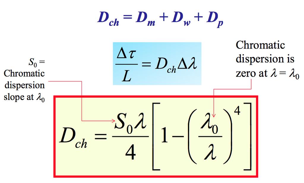
25 Chromatic Dispersion
26 Dispersion Flattened Fiber Fiber with flattened dispersion slope (schematic) (Corning)
27 Commercial Fibers
28 Dispersion Compensation
29 Dispersion Compensation
30 Dispersion and Maximum Bit Rate BIT RATE CAPACITY (bits per second) B 0.5 Δτ 1/ ( bits/sec) FWHM or FWHP FWHM: Full Width at Half Maximum FWHP: Full Width at Half Power
31 NRZ and RTZ T Information NRZ RZ Return-to-zero (RTZ) bit rate or data rate. Nonreturn to zero (NRZ) bit rate = RTZ bitrate
32 Maximum Bit Rate B Δτ 1 σ is Root Mean Square (RMS) deviation σ = 0.45 τ 1 Full Width Root Mean Square (rms) spread is Δt rms = σ. (The RTZ case)
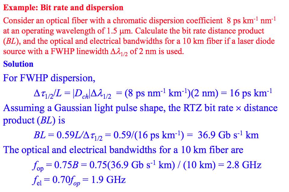
33 Bit Rate & Bit Rate Product Maximum Bit Rate Dispersion B 0.5 σ = 0.59 Δτ 1/ Δτ 1/ L = D ch Δλ 1/ BL 0.5L σ = 0.5 D ch σ λ = 0.59 D ch Δλ 1/ ( Gb s 1 km) Bit Rate Distance BL is: inversely proportional to dispersion inversely proportional to line width of laser (so, we need narrow frequency lasers!)
34 Intramodal & Intermodal Dispersion B 0.5 σ = 0.59 Δτ 1/ Maximum Bit Rate σ = + σ intermodal σ intramodal ) ( ) ( ) 1 / 1/ intermodal 1/ intramodal ( Δτ = Δτ + Δτ
35 Optical & Electrical Bandwidth An optical fiber link for transmitting analog signals and the effect of dispersion in the fiber on the bandwidth, f op. f op 0.75B 0.19 σ f el 0.71 f op

36 Pulse Shape and Maximum Bit Rate
37
38 Intermode Dispersion (MMF)
 Fiber")
39 Graded Index (GRIN) Fiber
40 Graded Index (GRIN) Fiber B' n c c B θ B' c/n b θ B' Ray A B'' n b b O 1 θ B c/n a θ A M Ray 1 n a a O' Which ray reaches O faster??

41 Graded Index (GRIN) Fiber! A ray in thinly stratifed medium becomes refracted as it passes from one layer to the next upper layer with lower n and eventually its angle satisfies TIR.! In a medium where n decreases continuously the path of the ray bends continuously.
 + δ Δ 5 + δ Profile Dispersion Parameter δ = n λ 1 dδ N g1δ dλ Minimum Intermodal Dispersion σ intermode L σ = σ intermodal Step Index Fiber n 1 0 3c Δ +σ")
42 Graded Index (GRIN) Fiber n(r) = n 1 1 Δ r γ a for ρ < a n(r) = n 1 1 Δ = n for ρ > a for γ = a " parabolic profile" Minimum Intermodal Dispersion γ o (4 + δ )(3 + δ ) + δ Δ 5 + δ Profile Dispersion Parameter δ = n λ 1 dδ N g1δ dλ Minimum Intermodal Dispersion σ intermode L σ = σ intermodal Step Index Fiber n 1 0 3c Δ +σ intramodal

43 GRIN FIBERS Commercial Fibers SMF FIBERS
![Graded Index (GRIN) Fiber & Rod Lenses NA = NA( r) = [ n( r) n ] 1/ Number of modes in a graded index fiber](/docs-images/72/66268675/images/44-0.jpg "Effective numerical aperture for GRIN fibers NA 1/ 1/ GRIN (1/ )( n1 n ) γ V M γ + GRIN Rod Lenses Point O is")

44 Graded Index (GRIN) Fiber & Rod Lenses NA = NA( r) = [ n( r) n ] 1/ Number of modes in a graded index fiber Effective numerical aperture for GRIN fibers NA 1/ 1/ GRIN (1/ )( n1 n ) γ V M γ + GRIN Rod Lenses Point O is on the rod face center and the lens focuses the rays onto O' on to the center of the opposite face. The rays from O on the rod face center are collimated out. O is slightly away from the rod face and the rays are collimated out.
Guided Propagation Along the Optical Fiber. Xavier Fernando Ryerson Comm. Lab
 Guided Propagation Along the Optical Fiber Xavier Fernando Ryerson Comm. Lab The Nature of Light Quantum Theory Light consists of small particles (photons) Wave Theory Light travels as a transverse electromagnetic
Waveguides and Optical Fibers
 Waveguides and Optical Fibers Dielectric Waveguides Light Light Light n n Light n > n A planar dielectric waveguide has a central rectangular region of higher refractive index n than the surrounding region
Fiber Optic Communication Systems. Unit-05: Types of Fibers. https://sites.google.com/a/faculty.muet.edu.pk/abdullatif
 Unit-05: Types of Fibers https://sites.google.com/a/faculty.muet.edu.pk/abdullatif Department of Telecommunication, MUET UET Jamshoro 1 Optical Fiber Department of Telecommunication, MUET UET Jamshoro
DIELECTRIC WAVEGUIDES and OPTICAL FIBERS
 DIELECTRIC WAVEGUIDES and OPTICAL FIBERS Light Light Light n 2 n 2 Light n 1 > n 2 A planar dielectric waveguide has a central rectangular region of higher refractive index n 1 than the surrounding region
Guided Propagation Along the Optical Fiber
 Guided Propagation Along the Optical Fiber The Nature of Light Quantum Theory Light consists of small particles (photons) Wave Theory Light travels as a transverse electromagnetic wave Ray Theory Light
Chapter 3 Signal Degradation in Optical Fibers
 What about the loss in optical fiber? Why and to what degree do optical signals gets distorted as they propagate along a fiber? Fiber links are limited by in path length by attenuation and pulse distortion.
Guided Propagation Along the Optical Fiber. Xavier Fernando Ryerson University
 Guided Propagation Along the Optical Fiber Xavier Fernando Ryerson University The Nature of Light Quantum Theory Light consists of small particles (photons) Wave Theory Light travels as a transverse electromagnetic
τ mod = T modal = longest ray path shortest ray path n 1 L 1 = L n 2 1
 S. Blair February 15, 2012 23 2.2. Pulse dispersion Pulse dispersion is the spreading of a pulse as it propagates down an optical fiber. Pulse spreading is an obvious detrimental effect that limits the
SIGNAL DEGRADATION IN OPTICAL FIBERS
 Volume Issue January 04, ISSN 348 8050 SIGNAL DEGRADATION IN OPTICAL FIBERS Gyan Prakash Pal, Manishankar Gupta,,, Assistant Professor, Electronics & Communication Engineering Department, Shanti Institute
UNIT-II : SIGNAL DEGRADATION IN OPTICAL FIBERS
 UNIT-II : SIGNAL DEGRADATION IN OPTICAL FIBERS The Signal Transmitting through the fiber is degraded by two mechanisms. i) Attenuation ii) Dispersion Both are important to determine the transmission characteristics
The absorption of the light may be intrinsic or extrinsic
 Attenuation Fiber Attenuation Types 1- Material Absorption losses 2- Intrinsic Absorption 3- Extrinsic Absorption 4- Scattering losses (Linear and nonlinear) 5- Bending Losses (Micro & Macro) Material
Lectureo5 FIBRE OPTICS. Unit-03
 Lectureo5 FIBRE OPTICS Unit-03 INTRODUCTION FUNDAMENTAL IDEAS ABOUT OPTICAL FIBRE Multimode Fibres Multimode Step Index Fibres Multimode Graded Index Fibres INTRODUCTION In communication systems, there
Section B Lecture 5 FIBER CHARACTERISTICS
 Section B Lecture 5 FIBER CHARACTERISTICS Material absorption Losses Material absorption is a loss mechanism related to material composition and fabrication process for the fiber. This results in dissipation
1. Evolution Of Fiber Optic Systems
 OPTICAL FIBER COMMUNICATION UNIT-I : OPTICAL FIBERS STRUCTURE: 1. Evolution Of Fiber Optic Systems The operating range of optical fiber system term and the characteristics of the four key components of
Optical Fiber Technology. Photonic Network By Dr. M H Zaidi
 Optical Fiber Technology Numerical Aperture (NA) What is numerical aperture (NA)? Numerical aperture is the measure of the light gathering ability of optical fiber The higher the NA, the larger the core
FIBER OPTICS. Prof. R.K. Shevgaonkar. Department of Electrical Engineering. Indian Institute of Technology, Bombay. Lecture: 4
 FIBER OPTICS Prof. R.K. Shevgaonkar Department of Electrical Engineering Indian Institute of Technology, Bombay Lecture: 4 Modal Propagation of Light in an Optical Fiber Fiber Optics, Prof. R.K. Shevgaonkar,
UNIT Write notes on broadening of pulse in the fiber dispersion?
 UNIT 3 1. Write notes on broadening of pulse in the fiber dispersion? Ans: The dispersion of the transmitted optical signal causes distortion for both digital and analog transmission along optical fibers.
Optical Fiber. n 2. n 1. θ 2. θ 1. Critical Angle According to Snell s Law
 ECE 271 Week 10 Critical Angle According to Snell s Law n 1 sin θ 1 = n 1 sin θ 2 θ 1 and θ 2 are angle of incidences The angle of incidence is measured with respect to the normal at the refractive boundary
ECEN689: Special Topics in Optical Interconnects Circuits and Systems Spring 2016
 ECEN689: Special Topics in Optical Interconnects Circuits and Systems Spring 016 Lecture 7: Transmitter Analysis Sam Palermo Analog & Mixed-Signal Center Texas A&M University Optical Modulation Techniques
Fiber Optic Communications
 Fiber Optic Communications ( Chapter 2: Optics Review ) presented by Prof. Kwang-Chun Ho 1 Section 2.4: Numerical Aperture Consider an optical receiver: where the diameter of photodetector surface area
EXPRIMENT 3 COUPLING FIBERS TO SEMICONDUCTOR SOURCES
 EXPRIMENT 3 COUPLING FIBERS TO SEMICONDUCTOR SOURCES OBJECTIVES In this lab, firstly you will learn to couple semiconductor sources, i.e., lightemitting diodes (LED's), to optical fibers. The coupling
There are lots of problems or challenges with fiber, Attenuation, Reflections, Dispersion and so on. So here we will look at these problems.
 The Hard theory The Hard Theory An introduction to fiber, should also include a section with some of the difficult theory. So if everything else in the book was very easily understood, then this section
Geometrical Optics Fiber optics The eye
 Phys 322 Lecture 16 Chapter 5 Geometrical Optics Fiber optics The eye First optical communication Alexander Graham Bell 1847-1922 1880: photophone 4 years after inventing a telephone! Fiberoptics: first
Total care for networks. Introduction to Dispersion
 Introduction to Dispersion Introduction to PMD Version1.0- June 01, 2000 Copyright GN Nettest 2000 Introduction To Dispersion Contents Definition of Dispersion Chromatic Dispersion Polarization Mode Dispersion
Fiber Optic Communications Communication Systems
 INTRODUCTION TO FIBER-OPTIC COMMUNICATIONS A fiber-optic system is similar to the copper wire system in many respects. The difference is that fiber-optics use light pulses to transmit information down
Department of Electrical Engineering and Computer Science
 MASSACHUSETTS INSTITUTE of TECHNOLOGY Department of Electrical Engineering and Computer Science 6.161/6637 Practice Quiz 2 Issued X:XXpm 4/XX/2004 Spring Term, 2004 Due X:XX+1:30pm 4/XX/2004 Please utilize
SYLLABUS Optical Fiber Communication
 SYLLABUS Optical Fiber Communication Subject Code : IA Marks : 25 No. of Lecture Hrs/Week : 04 Exam Hours : 03 Total no. of Lecture Hrs. : 52 Exam Marks : 100 UNIT - 1 PART - A OVERVIEW OF OPTICAL FIBER
Study of Optical Fiber Design Parameters in Fiber Optics Communications
 Kurdistan Journal of Applied Research (KJAR) Print-ISSN: 2411-7684 Electronic-ISSN: 2411-7706 kjar.spu.edu.iq Volume 2 Issue 3 August 2017 DOI: 10.24017/science.2017.3.52 Study of Optical Fiber Design
Chapter 8. Digital Links
 Chapter 8 Digital Links Point-to-point Links Link Power Budget Rise-time Budget Power Penalties Dispersions Noise Content Photonic Digital Link Analysis & Design Point-to-Point Link Requirement: - Data
Photonics and Optical Communication
 Photonics and Optical Communication (Course Number 300352) Spring 2007 Dr. Dietmar Knipp Assistant Professor of Electrical Engineering http://www.faculty.iu-bremen.de/dknipp/ 1 Photonics and Optical Communication
Optical systems have carrier frequencies of ~100 THz. This corresponds to wavelengths from µm.
 Introduction A communication system transmits information form one place to another. This could be from one building to another or across the ocean(s). Many systems use an EM carrier wave to transmit information.
Optical Digital Transmission Systems. Xavier Fernando ADROIT Lab Ryerson University
 Optical Digital Transmission Systems Xavier Fernando ADROIT Lab Ryerson University Overview In this section we cover point-to-point digital transmission link design issues (Ch8): Link power budget calculations
2 in the multipath dispersion of the optical fibre. (b) Discuss the merits and drawbacks of cut bouls method of measurement of alternation.
 Discuss the merits and drawbacks of cut bouls method of measurement of alternation.") B.TECH IV Year I Semester (R09) Regular Examinations, November 2012 1 (a) Derive an expression for multiple time difference tt 2 in the multipath dispersion of the optical fibre. (b) Discuss the merits
B.TECH IV Year I Semester (R09) Regular Examinations, November 2012 1 (a) Derive an expression for multiple time difference tt 2 in the multipath dispersion of the optical fibre. (b) Discuss the merits
Examination Optoelectronic Communication Technology. April 11, Name: Student ID number: OCT1 1: OCT 2: OCT 3: OCT 4: Total: Grade:
 Examination Optoelectronic Communication Technology April, 26 Name: Student ID number: OCT : OCT 2: OCT 3: OCT 4: Total: Grade: Declaration of Consent I hereby agree to have my exam results published on
UNIT I INTRODUCTION TO OPTICAL FIBERS
 UNIT I INTRODUCTION TO OPTICAL FIBERS 9 Evolution of fiber optic system Element of an Optical Fiber Transmission link Total internal reflection Acceptance angle Numerical aperture Skew rays Ray Optics
Fiber Optic Communication Link Design
 Fiber Optic Communication Link Design By Michael J. Fujita, S.K. Ramesh, PhD, Russell L. Tatro Abstract The fundamental building blocks of an optical fiber transmission link are the optical source, the
Comparison of FRD (Focal Ratio Degradation) for Optical Fibres with Different Core Sizes By Neil Barrie
 for Optical Fibres with Different Core Sizes By Neil Barrie") Comparison of FRD (Focal Ratio Degradation) for Optical Fibres with Different Core Sizes By Neil Barrie Introduction The purpose of this experimental investigation was to determine whether there is a dependence
Comparison of FRD (Focal Ratio Degradation) for Optical Fibres with Different Core Sizes By Neil Barrie Introduction The purpose of this experimental investigation was to determine whether there is a dependence
Bragg and fiber gratings. Mikko Saarinen
 Bragg and fiber gratings Mikko Saarinen 27.10.2009 Bragg grating - Bragg gratings are periodic perturbations in the propagating medium, usually periodic variation of the refractive index - like diffraction
EE 233. LIGHTWAVE. Chapter 2. Optical Fibers. Instructor: Ivan P. Kaminow
 EE 233. LIGHTWAVE SYSTEMS Chapter 2. Optical Fibers Instructor: Ivan P. Kaminow PLANAR WAVEGUIDE (RAY PICTURE) Agrawal (2004) Kogelnik PLANAR WAVEGUIDE a = (n s 2 - n c2 )/ (n f 2 - n s2 ) = asymmetry;
2. The Basic principle of optical fibre (Or) Working principle of optical fibre (or) Total internal reflection
 Working principle of optical fibre (or) Total internal reflection") Introduction Fibre optics deals with the light propagation through thin glass fibres. Fibre optics plays an important role in the field of communication to transmit voice, television and digital data signals
Introduction Fibre optics deals with the light propagation through thin glass fibres. Fibre optics plays an important role in the field of communication to transmit voice, television and digital data signals
Index of refraction varies significantly for broadband pulses
 Index of refraction varies significantly for broadband pulses Δt=10 fs Δλ =90nm index of refraction may vary by nearly 1% phase speed depends on n v φ (λ) = c n(λ) n phase relations will be lost as pulse
Chapter 18: Fiber Optic and Laser Technology
 Chapter 18: Fiber Optic and Laser Technology Chapter 18 Objectives At the conclusion of this chapter, the reader will be able to: Describe the construction of fiber optic cable. Describe the propagation
Lecture 8 Fiber Optical Communication Lecture 8, Slide 1
 Lecture 8 Bit error rate The Q value Receiver sensitivity Sensitivity degradation Extinction ratio RIN Timing jitter Chirp Forward error correction Fiber Optical Communication Lecture 8, Slide Bit error
Multimode Optical Fiber
 Multimode Optical Fiber 1 OBJECTIVE Determine the optical modes that exist for multimode step index fibers and investigate their performance on optical systems. 2 PRE-LAB The backbone of optical systems
The electric field for the wave sketched in Fig. 3-1 can be written as
 ELECTROMAGNETIC WAVES Light consists of an electric field and a magnetic field that oscillate at very high rates, of the order of 10 14 Hz. These fields travel in wavelike fashion at very high speeds.
CONTENTS. Chapter 1 Wave Nature of Light 19
 CONTENTS Chapter 1 Wave Nature of Light 19 1.1 Light Waves in a Homogeneous Medium 19 A. Plane Electromagnetic Wave 19 B. Maxwell's Wave Equation and Diverging Waves 22 Example 1.1.1 A diverging laser
Light Sources, Modulation, Transmitters and Receivers
 Optical Fibres and Telecommunications Light Sources, Modulation, Transmitters and Receivers Introduction Previous section looked at Fibres. How is light generated in the first place? How is light modulated?
NEW YORK CITY COLLEGE of TECHNOLOGY
 NEW YORK CITY COLLEGE of TECHNOLOGY THE CITY UNIVERSITY OF NEW YORK DEPARTMENT OF ELECTRICAL AND TELECOMMUNICATIONS ENGINEERING TECHNOLOGY Course : Prepared by: TCET 4102 Fiber-optic communications Module
Chapter 9 GUIDED WAVE OPTICS
 [Reading Assignment, Hecht 5.6] Chapter 9 GUIDED WAVE OPTICS Optical fibers The step index circular waveguide is the most common fiber design for optical communications plastic coating (sheath) core cladding
GRINTECH GmbH. product information.
 GRINTECH GmbH product information www.grintech.de GRIN rod lenses Gradient index lenses for fiber coupling and beam shaping of laser diodes z l d s f Order example: GT-LFRL-100-025-50-CC (670) Design wavelength
Lecture 3 Fiber Optical Communication Lecture 3, Slide 1
 Lecture 3 Dispersion in single-mode fibers Material dispersion Waveguide dispersion Limitations from dispersion Propagation equations Gaussian pulse broadening Bit-rate limitations Fiber losses Fiber Optical
FIBER OPTICS. Dr D. Arun Kumar Assistant Professor Department of Physical Sciences Bannari Amman Institute of Technology Sathyamangalam
 FIBER OPTICS Dr D. Arun Kumar Assistant Professor Department of Physical Sciences Bannari Amman Institute of Technology Sathyamangalam General Objective To understand the propagation of light through optical
SKP Engineering College
 SKP Engineering College Tiruvannamalai 606611 A Course Material on Optical Communication and Networks By M.Mageshbabu Assistant Professor Electronics and Communication Engineering Department Electronics
for SWL and LWL Fiber Systems Chromatic Dispersion Limited Link Lengths David Cunningham, Leonid Kazovsky* and M. Nowell
 Chromatic Dispersion Limited Link Lengths for SWL and LWL Fiber Systems IEEE 802 Plenary Meeting Vancouver, BC November 11-15, 1996 David Cunningham, Leonid Kazovsky* and M. Nowell Hewlett-Packard Laboratories
EC Optical Communication And Networking TWO MARKS QUESTION AND ANSWERS UNIT -1 INTRODUCTION
 EC6702 - Optical Communication And Networking TWO MARKS QUESTION AND ANSWERS UNIT -1 INTRODUCTION Ray Theory Transmission 1. Write short notes on ray optics theory. Laws governing the nature of light are
Lecture 12: Curvature and Refraction Radar Equation for Point Targets (Rinehart Ch3-4)
") MET 4410 Remote Sensing: Radar and Satellite Meteorology MET 5412 Remote Sensing in Meteorology Lecture 12: Curvature and Refraction Radar Equation for Point Targets (Rinehart Ch3-4) Radar Wave Propagation
MET 4410 Remote Sensing: Radar and Satellite Meteorology MET 5412 Remote Sensing in Meteorology Lecture 12: Curvature and Refraction Radar Equation for Point Targets (Rinehart Ch3-4) Radar Wave Propagation
Chromatic Dispersion Compensation in Optical Fiber Communication System and its Simulation
 Indian Journal of Science and Technology Supplementary Article Chromatic Dispersion Compensation in Optical Fiber Communication System and its Simulation R. Udayakumar 1 *, V. Khanaa 2 and T. Saravanan
Analysis of Self Phase Modulation Fiber nonlinearity in Optical Transmission System with Dispersion
 36 Analysis of Self Phase Modulation Fiber nonlinearity in Optical Transmission System with Dispersion Supreet Singh 1, Kulwinder Singh 2 1 Department of Electronics and Communication Engineering, Punjabi
Fiber Optics Dr. Vipul Rastogi Department of Physics Indian Institute of Technology, Roorkee. Lecture - 04 Salient features of optical fiber II
 Fiber Optics Dr. Vipul Rastogi Department of Physics Indian Institute of Technology, Roorkee Lecture - 04 Salient features of optical fiber II In the last lecture we had understood the propagation characteristics
Using Stock Optics. ECE 5616 Curtis
 Using Stock Optics What shape to use X & Y parameters Please use achromatics Please use camera lens Please use 4F imaging systems Others things Data link Stock Optics Some comments Advantages Time and
SYLLABUS. Optical Fiber Communication
 SYLLABUS Optical Fiber Communication Subject Code : IA Marks : 25 No. of Lecture Hrs/Week : 04 Exam Hours : 03 Total no. of Lecture Hrs. : 52 Exam Marks : 100 UNIT - 1 PART - A OVERVIEW OF OPTICAL FIBER
Unit-5. Lecture -4. Power Penalties,
 Unit-5 Lecture -4 Power Penalties, Power Penalties When any signal impairments are present, a lower optical power level arrives at the receiver compared to the ideal reception case. This lower power results
WHITE PAPER LINK LOSS BUDGET ANALYSIS TAP APPLICATION NOTE LINK LOSS BUDGET ANALYSIS
 TAP APPLICATION NOTE LINK LOSS BUDGET ANALYSIS WHITE PAPER JULY 2017 1 Table of Contents Basic Information... 3 Link Loss Budget Analysis... 3 Singlemode vs. Multimode... 3 Dispersion vs. Attenuation...
Optical Components for Laser Applications. Günter Toesko - Laserseminar BLZ im Dezember
 Günter Toesko - Laserseminar BLZ im Dezember 2009 1 Aberrations An optical aberration is a distortion in the image formed by an optical system compared to the original. It can arise for a number of reasons
Analysis of Dispersion of Single Mode Optical Fiber
 Daffodil International University Institutional Repository Proceedings of NCCIS November 007 007-11-4 Analysis of Dispersion of Single Mode Optical Fiber Hossen, Monir Daffodil International University
Lecture 2 Fiber Optical Communication Lecture 2, Slide 1
 Lecture General concepts Digital modulation in general Optical modulation Direct modulation External modulation Modulation formats Differential detection Coherent detection Fiber Optical Communication
Fundamentals of Electromagnetics With Engineering Applications by Stuart M. Wentworth Copyright 2005 by John Wiley & Sons. All rights reserved.
 Figure 7-1 (p. 339) Non-TEM mmode waveguide structures include (a) rectangular waveguide, (b) circular waveguide., (c) dielectric slab waveguide, and (d) fiber optic waveguide. Figure 7-2 (p. 340) Cross
Optical Communications and Networking 朱祖勍. Sept. 25, 2017
 Optical Communications and Networking Sept. 25, 2017 Lecture 4: Signal Propagation in Fiber 1 Nonlinear Effects The assumption of linearity may not always be valid. Nonlinear effects are all related to
Dr. Monir Hossen ECE, KUET
 Dr. Monir Hossen ECE, KUET 1 Outlines of the Class Principles of WDM DWDM, CWDM, Bidirectional WDM Components of WDM AWG, filter Problems with WDM Four-wave mixing Stimulated Brillouin scattering WDM Network
Concepts of optical signal processing and optical communications
 Concepts of optical signal processing and optical communications Electronic components allowing to control electric currents with electric currents (or voltages) and integration of a large number of such
Applied Optics. , Physics Department (Room #36-401) , ,
 , ,") Applied Optics Professor, Physics Department (Room #36-401) 2290-0923, 019-539-0923, shsong@hanyang.ac.kr Office Hours Mondays 15:00-16:30, Wednesdays 15:00-16:30 TA (Ph.D. student, Room #36-415) 2290-0921,
Applied Optics Professor, Physics Department (Room #36-401) 2290-0923, 019-539-0923, shsong@hanyang.ac.kr Office Hours Mondays 15:00-16:30, Wednesdays 15:00-16:30 TA (Ph.D. student, Room #36-415) 2290-0921,
Virtually Imaged Phased Array
 UDC 621.3.32.26:621.391.6 Virtually Imaged Phased Array VMasataka Shirasaki (Manuscript received March 11, 1999) A Virtually Imaged Phased Array (VIPA) is a simple design of an optical element which shows
Attenuation and Time Dispersion Measurements of Graded Index Polymer Optical Fiber for. Indoor Cellular Coverage
 Contemporary Engineering Sciences, Vol. 2, 2009, no. 2, 47-58 Attenuation and Time Dispersion Measurements of Graded Index Polymer Optical Fiber for Indoor Cellular Coverage S. Louvros and I. E. Kougias
Polarization Mode Dispersion compensation in WDM system using dispersion compensating fibre
 Polarization Mode Dispersion compensation in WDM system using dispersion compensating fibre AMANDEEP KAUR (Assist. Prof.) ECE department GIMET Amritsar Abstract: In this paper, the polarization mode dispersion
Performance Evaluation of 32 Channel DWDM System Using Dispersion Compensation Unit at Different Bit Rates
 Performance Evaluation of 32 Channel DWDM System Using Dispersion Compensation Unit at Different Bit Rates Simarpreet Kaur Gill 1, Gurinder Kaur 2 1Mtech Student, ECE Department, Rayat- Bahra University,
APPLICATION NOTE
 THE PHYSICS BEHIND TAG OPTICS TECHNOLOGY AND THE MECHANISM OF ACTION OF APPLICATION NOTE 12-001 USING SOUND TO SHAPE LIGHT Page 1 of 6 Tutorial on How the TAG Lens Works This brief tutorial explains the
Fiberoptic and Waveguide Sensors
 Fiberoptic and Waveguide Sensors Wei-Chih Wang Department of Mecahnical Engineering University of Washington Optical sensors Advantages: -immune from electromagnetic field interference (EMI) - extreme
 VALLIAMMAI ENGINEERING COLLEGE SRM Nagar, Kattankulathur 603 203. DEPARTMENT OF ELECTRONICS & COMMUNICATION ENGINEERING EC6702 OPTICAL COMMUNICATION AND NETWORKS QUESTION BANK IV YEAR VII SEM ACDEMIC YEAR:
Module 12 : System Degradation and Power Penalty
 Module 12 : System Degradation and Power Penalty Lecture : System Degradation and Power Penalty Objectives In this lecture you will learn the following Degradation during Propagation Modal Noise Dispersion
Introduction to Fiber Optics
 Introduction to Fiber Optics Dr. Anurag Srivastava Atal Bihari Vajpayee Indian Institute of Information Technology and Manegement, Gwalior Milestones in Electrical Communication 1838 Samuel F.B. Morse
EKT 465 OPTICAL COMMUNICATION SYSTEM. Chapter 2 OPTICAL FIBER COMMUNICATIONS
 EKT 465 OPTICAL COMMUNICATION SYSTEM Chapter 2 OPTICAL FIBER COMMUNICATIONS SEMESTER 1-2017/18 3 Credit Hours 222.3 Gbps pada 2017, daripada 6.4Gbps pada 2012 10/3/2017 2 Light Propagation & Transmission
Absorption: in an OF, the loss of Optical power, resulting from conversion of that power into heat.
 Absorption: in an OF, the loss of Optical power, resulting from conversion of that power into heat. Scattering: The changes in direction of light confined within an OF, occurring due to imperfection in
Teaching fiber-optic communications in engineering technology programs by virtual collaboration with industry
 Teaching fiber-optic communications in engineering technology programs by virtual collaboration with industry Djafar K. Mynbaev New York City College of Technology of the City University of New York, 300
MAHALAKSHMI ENGINEERING COLLEGE TIRUCHIRAPALLI
 MAHALAKSHMI ENGINEERING COLLEGE TIRUCHIRAPALLI - 621213 DEPARTMENT : ECE SUBJECT NAME : OPTICAL COMMUNICATION & NETWORKS SUBJECT CODE : EC 2402 UNIT II: TRANSMISSION CHARACTERISTICS OF OPTICAL FIBERS PART
OPTICAL NETWORKS. Building Blocks. A. Gençata İTÜ, Dept. Computer Engineering 2005
 OPTICAL NETWORKS Building Blocks A. Gençata İTÜ, Dept. Computer Engineering 2005 Introduction An introduction to WDM devices. optical fiber optical couplers optical receivers optical filters optical amplifiers
Speckle free laser projection
 Speckle free laser projection With Optotune s Laser Speckle Reducer October 2013 Dr. Selina Casutt, Application Engineer Bernstrasse 388 CH-8953 Dietikon Switzerland Phone +41 58 856 3011 www.optotune.com
Broadcast and distribution networks
 4/7/06 SYSTEM ARCHITECTURES Point-to-point links Point-to-point links constitute the simplest kind of lightwave systems The link length can vary from less than a kilometer (short haul) to thousands of
Lecture 2: Geometrical Optics. Geometrical Approximation. Lenses. Mirrors. Optical Systems. Images and Pupils. Aberrations.
 Lecture 2: Geometrical Optics Outline 1 Geometrical Approximation 2 Lenses 3 Mirrors 4 Optical Systems 5 Images and Pupils 6 Aberrations Christoph U. Keller, Leiden Observatory, keller@strw.leidenuniv.nl
Fiber Optics IV - Testing
 PDHonline Course E311 (3 PDH) Fiber Optics IV - Testing Instructor: Lee Layton, PE 2012 PDH Online PDH Center 5272 Meadow Estates Drive Fairfax, VA 22030-6658 Phone & Fax: 703-988-0088 www.pdhonline.org
Use of Statistical Moments for Evaluation of Far-Field Patterns
 Use of Statistical Moments for Evaluation of Far-Field Patterns Robert P. Dahlgren, Jacob A. Wysocki, and Kenneth D. Pedrotti Department of Electrical Engineering University of California Santa Cruz, CA
LECTURE NOTES OPTICAL FIBER COMMUNICATION (15A04701) IV B. Tech I Semester (JNTUA-R15) Mrs. N.Pranavi, Assistant Professor
 IV B. Tech I Semester (JNTUA-R15) Mrs. N.Pranavi, Assistant Professor") LECTURE NOTES ON OPTICAL FIBER COMMUNICATION (15A04701) 2018 2019 IV B. Tech I Semester (JNTUA-R15) Mrs. N.Pranavi, Assistant Professor CHADALAWADA RAMANAMMA ENGINEERING COLLEGE (AUTONOMOUS) Chadalawada
LECTURE NOTES ON OPTICAL FIBER COMMUNICATION (15A04701) 2018 2019 IV B. Tech I Semester (JNTUA-R15) Mrs. N.Pranavi, Assistant Professor CHADALAWADA RAMANAMMA ENGINEERING COLLEGE (AUTONOMOUS) Chadalawada
NETW 701: Wireless Communications. Lecture 5. Small Scale Fading
 NETW 701: Wireless Communications Lecture 5 Small Scale Fading Small Scale Fading Most mobile communication systems are used in and around center of population. The transmitting antenna or Base Station
HCS 50W, 60W & 80W. Data Sheet. Housed Collimated High Power Laser Diode Bar
 HCS 50W, 60W & 80W Housed Collimated High Power Laser Diode Bar Features: The II-VI Laser Enterprise HCS series of hard soldered collimated laser diode bars offer superior optical beam parameters with
Intensity Modulation. Wei-Chih Wang Department of Mechanical Engineering University of Washington. W. Wang
 Intensity Modulation Wei-Chih Wang Department of Mechanical Engineering University of Washington Why Intensity Modulation Simple optical setup Broadband or mono-chormatic light source Less sensitive but
Dispersion Measurements of High-Speed Lightwave Systems
 Lightwave Symposium Dispersion Measurements of Presented by Johann L. Fernando, Product Manager 3-1 Topics Chromatic dispersion concepts Agilent 86037C Chromatic Dispersion Measurement System Polarization
Parity and Plane Mirrors. Invert Image flip about a horizontal line. Revert Image flip about a vertical line.
 Optical Systems 37 Parity and Plane Mirrors In addition to bending or folding the light path, reflection from a plane mirror introduces a parity change in the image. Invert Image flip about a horizontal
High-Power, Passively Q-switched Microlaser - Power Amplifier System
 High-Power, Passively Q-switched Microlaser - Power Amplifier System Yelena Isyanova Q-Peak, Inc.,135 South Road, Bedford, MA 01730 isyanova@qpeak.com Jeff G. Manni JGM Associates, 6 New England Executive
End Capped High Power Assemblies
 Fiberguide s end capped fiber optic assemblies allow the user to achieve higher coupled power into a fiber core by reducing the power density at the air/ silica interface, commonly the point of laser damage.
Lecture 2: Geometrical Optics. Geometrical Approximation. Lenses. Mirrors. Optical Systems. Images and Pupils. Aberrations.
 Lecture 2: Geometrical Optics Outline 1 Geometrical Approximation 2 Lenses 3 Mirrors 4 Optical Systems 5 Images and Pupils 6 Aberrations Christoph U. Keller, Leiden Observatory, keller@strw.leidenuniv.nl
DEPARTMENT OF CSE QUESTION BANK
 DEPARTMENT OF CSE QUESTION BANK SUBJECT CODE: CS6304 SUBJECT NAME: ANALOG AND DIGITAL COMMUNICATION Part-A UNIT-I ANALOG COMMUNICATION 1.Define modulation? Modulation is a process by which some characteristics