Instructions MODIFICATION KIT MODEL SBM - 1O2-1 INTRODUCTION PARTS LIST FOR THE
|
|
|
- Dennis Thomas
- 5 years ago
- Views:
Transcription
1 Instructions FOR THE MODIFICATION KIT MODEL SBM - 1O2-1 INTRODUCTION This modification Kit applies to the following Heath Transceivers: 1. All Models HW-100, SB-100, SB-101 and SB-101W. 2. Any Model SB-102 that has a number lower than 5446 as the last four digits of the Series Number (on the blue and white label). The plate tank circuit of V6, the second transmitter mixer, is used in the receive mode as the plate circuit of V10, RF Amplifier. Due to tube Miller effects, additional capacity is required when receiving to permit the driver preselector to peak at the same dial setting in both transmit and receive modes. This modification uses automatic diode switching to add the required compensating capacity. PARTS LIST PART No QUAN- DESCRIPTION TITY k 1/2-watt resistor (brown-black-yellow) 1 1 M 1/2-watt resistor (brown-black-green) pf disc capacitor 1 1N4149 diode (cathode end marked with a band) 1 Black hookup wire 1 Blue and white identification label 1 3-lug terminal strip Instruction sheet Solder Since the 100 K resistor, under certain conditions, is dissipating around 0.9 watts (P=E^2/R), I replaced the ½ watt resistor that was originally installed in my HW-101 with a 100K, 2 watt resistor. I also replaced the 1N4149, which has a PRV of 75 VDC, with a 400 VDC rectifier diode which appears to work just as well for switching in this circuit PRINTED IN U.S.A.
 If you wish, temporarily remove the support rail which holds one end of the switch boards.")
 Solder the foot on the resistor lead directly to the foil at point 11 on the RF driver circuit board.")
2 Page 2 ( ) Remove the cabinet from the transceiver and turn the chassis bottom side up. ( ) Remove the coil cover. MODIFICATION PROCEDURE ( ) If you wish, temporarily remove the support rail which holds one end of the switch boards. ( ) Refer to Figure 1 and bend a small foot on the end of one lead of the 100 k (brownblack-yellow) resistor. ( ) Coat the foot with a liberal amount of solder. Figure 1 Figure 2 Refer to Figure 2 for the next three steps. ( ) Solder the foot on the resistor lead directly to the foil at point 11 on the RF driver circuit board. NOTE: A white-red-red wire (and possibly other components) are already soldered to this foil. ( ) Cut the leads of the 3.3 pf disc capacitor to 5/8. ( ) Bend a 1/8 foot on the end of one lead of the disc capacitor and solder this foot directly to the foil on the RF driver circuit board at point X as shown. Make sure the solder does not short circuit the foil to the switch shield.
. ( ) Connect the 1 M (brown-black-green) resistor from lug 1 (NS) to lug 3 (NS) of the terminal strip.")

3 Page 3 Figure 3 Figure 4 Refer to Figure 3 for the next two steps. ( ) Connect the cathode (banded) end of the 1N4149 diode to lug 2 of the 3-lug terminal strip (S-1). Connect the other lead to lug 1 of the terminal strip (NS). ( ) Connect the 1 M (brown-black-green) resistor from lug 1 (NS) to lug 3 (NS) of the terminal strip. ( ) Coat the terminal strip foot with solder. ( ) Refer to Figure 4 and solder the 3-lug terminal strip directly to the rear side (driver grid switch board side) of the front switch shield. Follow the dimensions given. Melt some solder on the switch shield at the point to which the terminal strip will be mounted. Then remelt the solder and hold the terminal strip foot snugly against the switch shield until the solder cools. ( ) Connect the free load of the 3.3 pf disc capacitor to lug 1 of the terminal strip (NS).
4 Page 4
 Prepare a 16 black hookup wire by removing 1/4 of insulation from each end of the wire. ( ) Connect one end of the black hookup wire to lug 3 of the terminal strip (S2).")
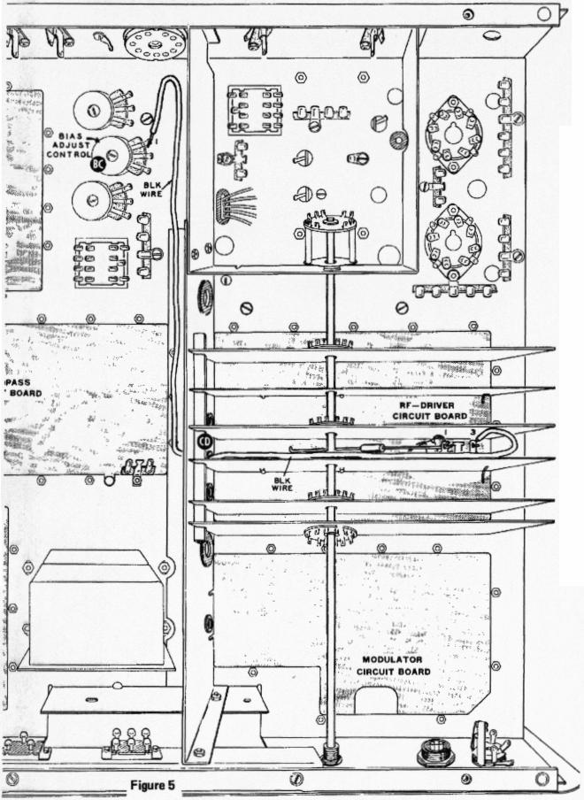
5 ( ) Connect the free end of the 100 k resistor to lug 1 of the terminal strip (S- 4). Make sure the capacitor and resistor leads do not touch any other wires or components. ( ) Prepare a 16 black hookup wire by removing 1/4 of insulation from each end of the wire. ( ) Connect one end of the black hookup wire to lug 3 of the terminal strip (S2). NOTE: Two sets of steps follow. Use only those steps applying to your transceiver. MODELS WITH "SB-" PREFIX: ( ) Refer to Figure 5 and route the black hookup wire over the bandswitch shaft, as shown, down through grommet CD, and back along the wiring harness to lug 1 of the Bias Adjust control Position the wire against the switch shield. ( ) Melt the solder on lug 1 of the Bias Adjust control and push the bare end of the black hookup wire through the opening in the lug. After the solder has cooled, tug on the wire to make sure it is securely connected. Proceed to the Final Assembly. Page 5
6 Page 6

7 Page 7
 melt the solder on lug 1 of control CT and push the bare end of the hookup wire through the opening in the lug. After the solder has cooled, tug on the wire to make sure it is securely connected.")
 If it was removed, replace the support rail and secure it with the hardware previously removed. Make sure all switch boards and shields fit into the proper slots in the comb on the support rail.")
8 MODEL HW-100: ( ) Refer to Figure 6 and route the hookup wire over the switch shaft, through grommet CD, and along the wiring harness to Bias control CT. ( ) melt the solder on lug 1 of control CT and push the bare end of the hookup wire through the opening in the lug. After the solder has cooled, tug on the wire to make sure it is securely connected. FINAL ASSEMBLY Figure 7 NOTE: You can secure the hookup wire to the wiring harness with electrical tape or with short pieces of hookup wire a shown in Figure 7. ( ) If it was removed, replace the support rail and secure it with the hardware previously removed. Make sure all switch boards and shields fit into the proper slots in the comb on the support rail. ( ) Replace the coil cover. Make sure the grounding clips on the under side of the cover fit over the switch shields. ( ) Refer to the alignment section of your assembly manual and peak the driver grid and driver plate coils. ( ) Replace the transceiver cabinet. ( ) Carefully peel away the backing paper from the blue and white identification label. Then press the label onto the rear of the cabinet. Be sure to refer to the numbers on this label in any communications you have with the Heath Company about this kit.. ( ) Copy the heavy, dark lines from the schematic on Page 8 onto the schematic diagram in your transceiver manual. This completes the modification. Page 8

9 CIRCUIT DESCRIPTION A negative voltage is always applied to the anode of D907 from the Bias Adjust control through resistor R954. When receiving, a higher positive voltage is applied to the anode of D907 from the screen circuit of V11 through resistor R955. As its anode is now positive, the diode conducts and acts as a closed switch to supply a ground to C955. This action places the capacitor in parallel with C421B and adds capacity to the plate tuned circuit. In the transmit mode, the positive voltage is removed by the opening of contacts 3 and 11 of RL2. The remaining negative voltage prevents D907 from conducting and it consequently acts as an open switch, removing the ground from C955. The capacitance of C955 is therefore removed from the plate circuit of V6.
sb401-eco.txt Engineering change orders or Service Bulletions (all) [No date on fiche] LMO Change
![sb401-eco.txt Engineering change orders or Service Bulletions (all) [No date on fiche] LMO Change](/thumbs/95/124083994.jpg "sb401-eco.txt Engineering change orders or Service Bulletions (all) [No date on fiche] LMO Change") Engineering change orders or Service Bulletions (all) [No date on fiche] LMO Change -1D The [PN 110-32] is no longer available. In order to use [PN 100-40-LMO] it is necessary to add decoupling capacitors
Engineering change orders or Service Bulletions (all) [No date on fiche] LMO Change -1D The [PN 110-32] is no longer available. In order to use [PN 100-40-LMO] it is necessary to add decoupling capacitors
Modifying The Heath HA-14 For 6 Meters Greg Chartrand - W7MY 4/22/07
 Introduction The Heathkit HA-14 was one of the few electron tube linear amplifiers intended for mobile use but few were purchased with the 12 volt mobile power supply. Most hams bought the HA-14 for base
A 75-Watt Transmitter for 3 Bands Simplified Shielding and Filtering for TVI BY DONALD H. MIX, W1TS ARRL Handbook 1953 and QST, October 1951
 A 75-Watt Transmitter for 3 Bands Simplified Shielding and Filtering for TVI BY DONALD H. MIX, W1TS ARRL Handbook 1953 and QST, October 1951 The transmitter shown in the photographs is a 3-stage 75-watt
Hot Water for the K2. K1RFD Building the K2 More K2 Photos. Using an HW-101 as a 100-watt PA. Hot Water for the K2. EchoStation
 Page 1 of 5 K1RFD Building the K2 More K2 Photos EchoStation Using an HW-101 as a 100-watt PA When I was a young ham in 1977, I saved money to buy and build a Heathkit HW-101. The rig has served me well
The Wave (K-MOD103) GUITAR DWELL REVERB REVERB SWITCH ON OUT OFF
 GUITAR DWELL REVERB REVERB SWITCH ON OUT OFF") The Wave (K-MOD103) OUT IN GUITAR IN DWELL REVERB REVERB SWITCH ON GUITAR OUT POWER ON OFF OFF Please note, there are no labels for this kit. The controls, switches and connectors have only been labeled
The Wave (K-MOD103) OUT IN GUITAR IN DWELL REVERB REVERB SWITCH ON GUITAR OUT POWER ON OFF OFF Please note, there are no labels for this kit. The controls, switches and connectors have only been labeled
May 23, Diode Leakage In The SB-100, SB-101, HW-100
 May 23, 1974 Diode Leakage In The, SB-101, HW-100-1 The silicon diodes used in the SB100 & SB101 are standard power diodes rated at 500PIV & 750MA. For each condition described, the diodes should be replaced
Assembly Instructions for the 1.5 Watt Amplifier Kit
 Assembly Instructions for the 1.5 Watt Amplifier Kit 1.) All of the small parts are attached to a sheet of paper indicating both their value and id. 2.) Leave the parts affixed to the paper until you are
NERVE TESTER KIT MODEL K-20. Assembly and Instruction Manual. Elenco Electronics, Inc.
 NERVE TESTER KIT MODEL K-20 Assembly and Instruction Manual Elenco Electronics, Inc. Copyright 1989 Elenco Electronics, Inc. Revised 2002 REV-E 753220 PARTS LIST If you are a student, and any parts are
D. Gillespie Designs. SCA-35 Capacitor Board. Installation Manual. D. Gillespie Designs with EFB TM
 D. Gillespie Designs SCA-5 Capacitor Board with EFB TM Installation Manual D. Gillespie Designs www.tronola.com Thank you for choosing our SCA-5 Capacitor Board with *EFB. We feel it is the single most
DIODE / TRANSISTOR TESTER KIT
 DIODE / TRANSISTOR TESTER KIT MODEL DT-100K Assembly and Instruction Manual Elenco Electronics, Inc. Copyright 1988 Elenco Electronics, Inc. Revised 2002 REV-K 753110 DT-100 PARTS LIST If you are a student,
Manual AMERITRON QSK-5PC T/R SWITCH PC BOARD INTRODUCTION
 Manual Instruction AMERITRON QSK-5PC T/R SWITCH PC BOARD INTRODUCTION The Ameritron QSK-5PC is a PIN diode QSK circuit board designed for use in Ameritron's AL-80A, AL-80B, AL-82, AL-1500 and AL- 1200
HW-8-TR V3 PARTS LIST
 HW-8-TR V3 PARTS LIST Qty Ref Description Markings 4C2 C3 C4 C5 Capacitor Disc.1ls.1uF 104 1 C1 Capacitor Disc.2ls.1uF 100V 104 1 QSKMOD-C92 Capacitor Electrolytic 1uF 50V 1 QSKMOD Capacitor Mylar.47uF
A 100-Watt Transmitter Using a Pair of VT1625s
 12/16/2007 6:00 PM VT1625 100 Watt Transmitter A 100-Watt Transmitter Using a Pair of VT1625s FIG. 10.6 A 100-watt transmitter for five bands, using salvaged TV power transformer and surplus 1625 amplifier
BEST BMET CBET STUDY GUIDE MODULE ONE
 BEST BMET CBET STUDY GUIDE MODULE ONE 1 OCTOBER, 2008 1. The phase relation for pure capacitance is a. current leads voltage by 90 degrees b. current leads voltage by 180 degrees c. current lags voltage
Building the Sawdust Regenerative Receiver
 Building the Sawdust Regenerative Receiver Introduction The Sawdust is a super regenerative receiver using the basic Armstrong design architecture. The receiver uses one toroidal transformer to provide
CONSTRUCTION. Refer to schematic and component location diagrams during assembly
 HAMTRONICS VHF RECEIVING CONVERTERS CONSTRUCTION, ALIGNMENT, & INSTALLATION INSTRUCTIONS GENERAL DESCRIPTION. The CA( ) series of VHF Receiving Converter modules are designed to amplify and convert the
Some KWM-2/2A Tricks. January By Georges, F6CER CCAE# 098. Some KWM-2/2A Tricks -
 Some KWM-2/2A Tricks January 2016 By Georges, F6CER CCAE# 098 Some KWM-2/2A Tricks Most of the KWM-2 transceivers that can be found in Europe belong to the first generation manufactured at the beginning
Find a place where you can work through completion, without disturbing your
 Scan by Manual Manor ARIES SYSTEM 300 MUSIC SYNTHESIZER Page I of 4 MODULE AR-334 SEQUENCER ASSEMBLY INSTRUCTIONS It is recommended that you do the following before you proceed: Find a place where you
DIODE / TRANSISTOR TESTER KIT
 DIODE / TRANSISTOR TESTER KIT MODEL DT-100K 99 Washington Street Melrose, MA 02176 Phone 781-665-1400 Toll Free 1-800-517-8431 Visit us at www.testequipmentdepot.com Assembly and Instruction Manual Elenco
AM RADIO KIT MODEL AM-780K. Assembly and Instruction Manual
 AM RADIO KIT MODEL AM-780K Assembly and Instruction Manual Elenco Electronics, Inc. Copyright 2007, 1999 by Elenco Electronics, Inc. All rights reserved. Revised 2007 REV-F 753108 No part of this book
Building the Sawdust Regenerative Receiver
 Building the Sawdust Regenerative Receiver Introduction The Sawdust is a super regenerative receiver using the basic Armstrong design architecture. The receiver uses one toroidal transformer to provide
Telecaster Wiring Kits Please Read All Instructions Before Beginning. Tools you will need: Soldering tips: Removing Current Wiring: Step 1. Step 2.
 Telecaster Wiring Kits Please Read All Instructions Before Beginning. Tools you will need: Soldering Iron (35 watt preferably) Solder Wet Sponge Wire Clippers Wire Strippers 3/8 Drill Bit 5/32 Drill Bit
Some hints/tips on how to assemble nice COAX TRAPS!
 Some hints/tips on how to assemble nice COAX TRAPS! Before we start to assemble our traps, here some general info as introduction : Coax traps are cheap, easy to assemble in a reproducible manner, very
Pacific Antenna Field Strength Indicator Kit
 Pacific Antenna Field Strength Indicator Kit Description The Field Strength Indicator kit from Pacific Antenna provides a visual way to monitor the presence and relative strength RF fields through the
Hendricks QRP Kits The Twofer Rev
 Hendricks QRP Kits The Twofer Rev 1 11-15-06 1. Description The Twofer is a classic QRP transmitter that s easy to assemble and operate. It uses a JFET VXO (variable crystal oscillator), driver stage and
Building a Bitx20 Version 3
 Building a Bitx20 Version 3 The board can be broken into sections and then built and tested one section at a time. This will make troubleshooting easier as any problems will be confined to one small section.
MINI FM PHONE TRANSMITTER KIT
 MINI FM PHONE TRANSMITTER KIT Description: This is a subminiature FM telephone transmitter capable of transmitting both sides of a telephone conversation to most any FM receiver up to 1/4 mile away. When
LED ROBOT BLINKER KIT
 LED ROBOT BLINKER KIT MODEL K-17 Assembly and Instruction Manual Elenco Electronics, Inc. Copyright 1989, 1998 Elenco Electronics, Inc. Revised 2001 REV-J 753217 PARTS LIST If any parts are missing or
THE RING RESONATOR (K-975)
") THE RING RESONATOR (K-975) OUTPUT BOOST The Ring Resonator An Octave Up Fuzz Modkitsdiy.com 9 VDC CENTER (-) ADAPTER TO AMP IN FROM GUITAR OUT Unplug when not in use to save battery life. Use these instructions
THE RING RESONATOR (K-975) OUTPUT BOOST The Ring Resonator An Octave Up Fuzz Modkitsdiy.com 9 VDC CENTER (-) ADAPTER TO AMP IN FROM GUITAR OUT Unplug when not in use to save battery life. Use these instructions
Mapletree Audio Design SR70A Special Red Driver Module for Dynaco ST-70
 Mapletree Audio Design S70A Special ed Driver Module for Dynaco ST-70 Installation instructions ev. Jan. 9/ The Special ed S70A driver module is a drop in replacement for the original driver board of the
The Tellun Corporation. TLN-861 Dunsel. User Guide, Rev Scott Juskiw The Tellun Corporation
 The Tellun Corporation TLN-861 Dunsel User Guide, Rev. 1.0 Scott Juskiw The Tellun Corporation scott@tellun.com TLN-861 User Guide Revision 1.0 August 31, 2006 1. Introduction The TLN-861 Dunsel is a collection
SPACE WAR GUN KIT MODEL K-10. Assembly and Instruction Manual. Elenco Electronics, Inc.
 SPACE WAR GUN KIT MODEL K-10 Assembly and Instruction Manual Elenco Electronics, Inc. Copyright 1989 Elenco Electronics, Inc. Revised 2001 REV-H 753210A PARTS LIST Contact Elenco Electronics (address/phone/e-mail
The ETO-Alpha 89 ETO-Alpha 89
 ETO-Alpha 89 The 89 was produced from 12/92 to 9/2000, 408 units were built during this time. These units were much like the 86, but with many updates and refinements. The 89 uses a pair of 3CX800A7 triodes
LBI-4938C. Mobile Communications MASTR II POWER AMPLIFIER MODELS 4EF4A1,2,3. Printed in U.S.A. Maintenance Manual
 C Mobile Communications MASTR II POWER AMPLIFIER MODELS 4EF4A1,2,3 Printed in U.S.A. Maintenance Manual TABLE OF CONTENTS DESCRIPTION.................................................... 1 CIRCUIT ANALYSIS.................................................
REPAIRING THE RM KL400 LINEAR AMPLIFIER.
 REPAIRING THE RM KL400 LINEAR AMPLIFIER. Les Carpenter G4CNH December 2012 Page 1 of 20 The following is a step by step guide to fixing your KL400 amplifier. Each part will be individually tested up to
Copyright 2012, R. Eckweiler & OCARC, Inc. Page 1 of 8
 HOM rev. new Heathkit of the Month #36: by Bob Eckweiler, AF6C Heathkit of the Month #36 - SB-301 HF Ham Band Receiver Heathkit SB-301 HF Ham Band Receiver Introduction: Shortly after graduating from college
Fig. 1 The SB-51 as supplied.
 The SB-51 SSB adapter (Fig. 1) from is designed specifically as an accessory for the Collins R-388 and 51J series receivers. It provides enhanced performance in SSB and CW modes. Performance in AM mode
TEN-TEc INSTRUCTION SHEET MODEL KRS-A
 3-75 TEN-TEc NSTRUCTON SHEET MODEL KRS-A, GENERAL The KRS-A is a solid state, integrated circuit electronic keyer incorporating a reed relay as the actual keying component. t can be used to key all gridblocked
HAMTRONICS LPA 2-25R REPEATER POWER AMPLIFIER: ASSEMBLY, INSTALLATION, & MAINTENANCE
 HAMTRONICS LPA 2-25R REPEATER POWER AMPLIFIER: ASSEMBLY, INSTALLATION, & MAINTENANCE GENERAL INFORMATION. The Power Amplifier is a class C device designed to be installed as an integral part of a transmitter
UNITED MOTORS SERVICE AUTO RADIO BULLETIN
 UNITED MOTORS SERVICE DIVISION OF GENERAL MOTORS CORPORATION General Offices - Detroit AUTO RADIO BULLETIN Bulletin 6D-854 Date 11-1-54 Page 1 FIRST ISSUE GENERAL SUBJECT: SERVICE INSTRUCTIONS - 12V CHEVROLET
HOM rev. new Heathkit of the Month #79: by Bob Eckweiler, AF6C. Heath of the Month #79 - VF-1 VFO AMATEUR RADIO - SWL
 Heathkit of the Month #79: by Bob Eckweiler, AF6C AMATEUR RADIO - SWL Heathkit VF-1 External VFO (Variable Frequency Oscillator). Introduction: In 1951 the FCC totally revamped the license classes for
You Just Brought an Old Radio Home: Now What Do You Do?
 You Just Brought an Old Radio Home: Now What Do You Do? Raymond Cady goldenageradiorestoration.com Whether you are just beginning to collect antique radios or you have been at it for a number of years,
PM24 Installation Instructions
 Marchand Electronics Inc. PO Box 473, Webster, NY 14580 Tel:(716) 872-0980 Fax:(716) 872-1960 info@marchandelec.com http://www.marchandelec.com (c)1997 Marchand Electronics Inc. PM24 Installation Instructions
IPR LA-3 KIT last update 15 march 06
 IPR LA-3 KIT last update 15 march 06 PART-2: Audio Circuitry CIRCUIT BOARD LAYOUT: Power and Ground Distribution Now that your power supply is functional, it s time to think about how that power will be
Copyright 2016, R. Eckweiler & OCARC, Inc. Page 1 of 7
 Heathkit of the Month: by Bob Eckweiler, AF6C ELECTRONIC TEST EQUIPMENT Heathkit IM-38 AC Vacuum Tube Voltmeter (VTVM). Introduction: Back in March of 2013 Heathkit of the Month #47 discussed the Heathkit
! February 9, 1970 GR-78!! Bulletin No: Transistor General Coverage Rcvr!
 ! February 9, 1970 GR-78-1! Rocker Switches [PN 60-45] S.P.S.T. switch is being replaced by [PN 60-48] D.P.D.T. switch with improved contacts. Four of the six lugs are removed when it is used as a S.P.S.T.
LED Field Strength Indicator Kit
 LED Field Strength Indicator Kit Description The Field Strength Indicator kit from Qrpkits.com provides a visual way to monitor RF fields through the brightness of an LED. It will respond to RF fields
MODEL 1215 ANTENNA TUNER KIT ASSEMBLY & OPERATIONAL MANUAL
 MODEL 1215 ANTENNA TUNER KIT ASSEMBLY & OPERATIONAL MANUAL Release B 6/28/11 1 1215 Antenna Tuner Manual Part # 74449 2 1215 Antenna Tuner Manual Part # 74449 TABLE OF CONTENTS NOTE: This manual is divided
& ' (wire, inches) 16 black Tef-Flex 16 Black Lex 32 Red Lex 48 Blue Tef-Flex 32 White Tef-Flex
 16 black Tef-Flex 16 Black Lex 32 Red Lex 48 Blue Tef-Flex 32 White Tef-Flex") ! " # $! " % Qty Part (woofer) 1 4.40mH 16 AWG inductor 1 10.0uF Yellow film capacitor 1 5.62 Ohm NORTH resistor (tweeter) 1 8uF Yellow film capacitor 1 0.56mH 16 AWG inductor 1 3.32 Ohm NORTH resistor
! " # $! " % Qty Part (woofer) 1 4.40mH 16 AWG inductor 1 10.0uF Yellow film capacitor 1 5.62 Ohm NORTH resistor (tweeter) 1 8uF Yellow film capacitor 1 0.56mH 16 AWG inductor 1 3.32 Ohm NORTH resistor
Assembly Instructions for the FRB FET FM 70 Watt Amp
 Assembly Instructions for the FRB FET FM 70 Watt Amp 1.) Orient the circuit board with the diagram 2.) Use a narrow chisel tip 25-30 watt soldering iron for assembly 3.) All the small parts are taped onto
Specimen Products Single Ended Stereo Amp Instruction Book
 Specimen Products Single Ended Stereo Amp Instruction Book Specimen tube amplifier designs are informed by decades of servicing and building musical instrument amps. As a result of being subjected to the
TELEPHONE BUG KIT MODEL K-35. Assembly and Instruction Manual
 TELEPHONE BUG KIT MODEL K-35 Assembly and Instruction Manual Elenco Electronics, Inc. Copyright 2010, 1989 by Elenco Electronics, Inc. All rights reserved. Revised 2010 REV-L 753235 No part of this book
 KILOWATT GROUNDED-GRID LINEAR AMPLIFIER (Radiotron HB) Grounded-grid amplifiers The input voltage is applied to the cathode, the grid is earthed, and the output is taken from the plate, being in phase
ig-5282 spec.txt IG-5282 Audio Generator
 IG-5282 Audio Generator ig-5282 spec.txt The Heathkit IG-5282 Audio Generator is an audio frequency signal generator. It provides sine wave and square wave signals that may be used as a signal source for
1.1 Original Amplifier Professional construction well made. No markings. Based on R&H Feb Watt Amplifier.
 4/03/2018 Australian 5W Combo Page 1 of 6 1. Summary Combo 5W Valve Amplifier and 8 Rola speaker. Unknown maker., Dec 2017. 1.1 Original Amplifier Professional construction well made. No markings. Based
THE AGGRESSOR (K-995)
") THE AGGRESSOR (K-99) TONE VOLUME DISTORTION MID-SHIFT SWITCH LED The Aggressor Distortion Pedal Modkitsdiy.com 9 VDC CENTER (-) ADAPTER TO AMP IN FROM GUITAR OUT Unplug when not in use to save battery
THE AGGRESSOR (K-99) TONE VOLUME DISTORTION MID-SHIFT SWITCH LED The Aggressor Distortion Pedal Modkitsdiy.com 9 VDC CENTER (-) ADAPTER TO AMP IN FROM GUITAR OUT Unplug when not in use to save battery
IC-765: Installing the Inrad Roofing Filter Mod
 IC-765: Installing the Inrad Roofing Filter Mod The Icom IC-765 roofing filter mod consists of a 6-pole, 4 khz wide filter followed by a high dynamic range, feedback amplifier. The amplifier provides enough
WA3RNC 30 METER CRYSTALPLEXER TRANSMITTER KIT ASSEMBLY INSTRUCTIONS
 WA3RNC 30 METER CRYSTALPLEXER TRANSMITTER KIT ASSEMBLY INSTRUCTIONS Description The WA3RNC 30 Meter Crystalplexer is a low power crystal controlled QRP transmitter offering a significantly improved tuning
HANDS-ON LAB INSTRUCTION SHEETS MODULE
 HANDS-ON LAB INSTRUCTION SHEETS MODULE 1 MEASURING RESISTANCE AND VOLTAGE NOTES: 1) Each student will be assigned to a unique Lab Equipment number MS01-MS30 which will match to a Tool Kit and a Radio Shack
NOTE: The relay coil is polarity sensitive
 External QSK T/R Switch for HF Amplifiers Phil Salas AD5X Like many HF amplifiers, my Ameritron ALS-600 uses a power relay for T/R switching. The long 15-20ms enable/release time of this relay makes the
HALLICRAFTERS SERVICE HINT NO. 21 October 20, Production Run Identification (Refer Service Policy Letter #9, dated Nov.
 HALLICRAFTERS SERVICE HINT NO. 21 October 20, 1947 SUBJECT: DISCUSSION: Model SX-42 Receiver Production Run Identification (Refer Service Policy Letter #9, dated Nov. 14, 1946) * * * * * * * * * * * *
Step by Step Building PJ meter ARDF Receiver Kit. CRKITS.COM August 5, 2013
 Step by Step Building PJ-80 80-meter ARDF Receiver Kit CRKITS.COM August 5, 2013 What is ARDF? ARDF is the abbreviation of Amateur Radio Direction Finding, or so called Fox Hunting. If you are looking
Technical Application Note #5
 CRC CACTUS Radio Club, Inc. This Technical Application Note describes modifications, duplexing and tuning instructions to the Motorola Mitrek 406-420 MHz mobile radio. The following instructions are individually
LESLIE CONSOLE CONNECTOR KIT 8400 INSTALLATION INSTRUCTIONS
 LESLIE CONSOLE CONNECTOR KIT 8400 INSTALLATION INSTRUCTIONS FOR USE WITH: LESLIE Speaker Models: 122, 122RV, 222, or 222RV in conjunction with HAMMOND Speaker HAMMOND Organ Models: A, B, C, D, E, RT, BV,
The 15 meter section was moved
 After 2 years or so making various adjustments to the original LPF filter configuration, and noting some of the changes which could be made to the board to make it easier to construct, tune, and reconfigure
THE THUNDERDRIVE (K-950)
") THE THUNDERDRIVE (K-950) OUTPUT DISTORTION Unplug when not in use to save battery life. TO AMP IN The Thunderdrive Modkitsdiy.com FROM GUITAR OUT Use these instructions to learn: How to build an effects
THE THUNDERDRIVE (K-950) OUTPUT DISTORTION Unplug when not in use to save battery life. TO AMP IN The Thunderdrive Modkitsdiy.com FROM GUITAR OUT Use these instructions to learn: How to build an effects
Assembly Instructions
 Assembly Instructions for the PA3 v2.0 Amplifier Kit PA3 Amplifier shown mounted on HS2 Heat Sink (The HS2 shown here is not included with this kit.) 27 February 2016 2013-2016 by Ralph Hartwell Spectrotek
4X150A/7034 Radial Beam Power Tetrode
 4X15A/734 Radial Beam Power Tetrode T The Svetlana 4X15A/734 is a compact radial beam tetrode. The 4X15A is intended for Class AB SSB linear RF amplifier service. It is intended for stationary and mobile
PL8877/ 3CX1500A7 High-Mu Power Triode
 PL8877/ 3CX1500A7 High-Mu Power Triode The Penta Laboratories PL8877/3CX1500A7 is a rugged ceramic and metal power triode designed for use as cathode driven Class AB2 or Class B amplifi er in audio or
Line-Following Robot
 1 Line-Following Robot Printed Circuit Board Assembly Jeffrey La Favre October 5, 2014 After you have learned to solder, you are ready to start the assembly of your robot. The assembly will be divided
Spectrian 2304 MHz SSPA. Garry C. Hess, K3SIW June 11, 2004
 Spectrian 2304 MHz SSPA Garry C. Hess, K3SIW June 11, 2004 A solid-state power amplifier (SSPA) manufactured by Spectrian can produce on the order of 200 W linear output 1 at 2304 MHz with little modification.
PM124 Installation Instructions. See important note about revisions of this board on the last page.
 Marchand Electronics Inc. PO Box 473, Webster, NY 14580 Tel:(716) 872-0980 Fax:(716) 872-1960 info@marchandelec.com http://www.marchandelec.com (c)1997 Marchand Electronics Inc. PM124 Installation Instructions
NEW DESIGN***DEM Part Number FRS***NEW DESIGN Low power 144 MHz Transverter for the Flex Radio System SDR-1000 Operating Specifications:
 NEW DESIGN***DEM Part Number 144-28FRS***NEW DESIGN Low power 144 MHz Transverter for the Flex Radio System SDR-1000 Operating Specifications: Operating Voltage: 12.0-15.5 VDC, 13.8 nominal Current Drain:
Assembly Instructions for B7971 Smart Socket
 Assembly Instructions for B7971 Smart Socket Identification and installation of the resistors, Fig1 Segment 1,R1, 22k Segment 4, R4, 22k Segment 2, R2, 27k Segment 3, R3, 27k Segment 5, R5, 27k Segment
A Transmatch for Balanced or Unbalanced Lines
 A Transmatch for Balanced or Unbalanced Lines Most modern transmitters are designed to operate into loads of approximately 50 Ω. Solid-state transmitters produce progressively lower output power as the
Transistors As RF Power Amplifiers
 A PUBLICATION OF THE RCA ELECTRON TUBE DIVISION VOL. 21, NO. 4 1961, RADIO CORPORATION OF AMERICA DECEMBER, 1961 Transistors As RF Power Amplifiers By J. B. Fisher, WA2CMR/6 Field Sales Engineering RCA
DEM Part Number L144-28INTCK 144 MHz Transverter Kit and complete kit
 DEM Part Number L144-28INTCK 144 MHz Transverter Kit and complete kit Power Out: Noise Figure and Gain: DC Power Requirement: 50 mw linear minimum 3.5 db NF nominal, 5 dbg maximum 12-15.5 VDC, 13.8 nominal
AM RADIO KIT MODEL AM-780K. Assembly and Instruction Manual ELENCO
 AM-780K_REV-K_050416.qxp_AM-780K_REV-K_050416 5/10/16 8:13 AM Page 1 AM RADIO KIT MODEL AM-780K Assembly and Instruction Manual ELENCO Copyright 2016, 1999 by Elenco Electronics, Inc. All rights reserved.
Progeny Integrated Mobile Unit Unpacking/Assembly Guide
 Summary: The following instruction will guide you through the unpacking and installation of the Progeny Mobile Unit. Any question or concerns or suggestions should be directed to Progeny Technical Support
Hoffman AB763-2 Channel BOM
 Updated 5/21/2018 Item Component Wattage Notes R1 1m 1/2 watt R2 1m 1/2 watt R3 33k 1/2 watt Single input jack R3 68k 1/2 watt Dual input jacks R4 33k 1/2 watt Single input jack R4 68k 1/2 watt Dual input
The Electro-Magnetic Spectrum
 The Electro-Magnetic Spectrum Part Three In This Issue: All about Tubes How a diode rectifier works How a triode amplifier works How the mixer in your receiver works Dear Friends: For quite some time I
INTERNATIONAL RADIO CORP
 I N R A D INTERNATIONAL RADIO CORP 13620 Tyee Road Umpqua, OR 97486 (541) 459-5623 fax (541) 459 5632 E-mail: inrad@rosenet.net www.qth.com/inrad IC-775 ROOFING FILTER INSTALLATION INSTRUCTIONS The IC-775
Blue Ring Tester Kit Assembly & User Manual
 Blue Ring Tester Kit Assembly & User Manual Alltronics LLC/AnaTek Instruments 2761 Scott Blvd, Santa Clara, CA, 95050, USA March 2015 Edition Tel: 408-778-3868, Fax: 408-778-2558, E mail : tech@alltronics.com
TS-930: Installing the Inrad Roofing Filter Mod
 TS-930: Installing the Inrad Roofing Filter Mod The TS-930 roofing filter mod consists of a 6 pole, 4 to 5 khz wide filter followed by a high dynamic range, feedback amplifier. The amplifier provides enough
Easy Transmitter. Support ETX_REV5_Manual V2.7 Revised
 Easy Transmitter Introduction The Easy Transmitter kit from qrpkits.com provides a basic, crystal controlled transmitter with VXO tuning to provide a small tuning range around the crystal frequency. It
KWM-2/2A Transceiver THE COLLINS KWM-2/2A TRANSCEIVER
 KWM-2/2A Transceiver Click the photo to see a larger photo Click "Back" button on browser to return Courtesy of Norm - WA3KEY THE COLLINS KWM-2/2A TRANSCEIVER Unmatched for versatility, dependability and
Treetop Circuits Owner s Manual for SB-SB-600 Adapter Version 1
 The SB-600 SSB adapter from Treetop Circuits (Fig. 1) is designed specifically as an accessory to the Hammarlund SP-600 series of receivers. It provides enhanced performance on SSB and CW signals, using
About Q. About Q, Xtal Set Society, Inc
 About Q, Xtal Set Society, Inc In the crystal radio hobby and in electronics in general Q can refer to a number of things: the Q of a coil, the Q of a circuit, the quality factor of some item, or the label
Reconstructing my Hallicrafters SX-28A. John Staples, W6BM
 February 2017 Reconstructing my Hallicrafters SX-28A John Staples, W6BM I say reconstructing instead of recapping because in my youthful ignorance, I took a perfectly good receiver, stripped it and rebuilt
HEATH COMPANY PHONE DIRECTORY YOUR HEATHKIT 90-DAY FULL WARRANTY. Numérisation, Pascal Chour, 01/2004 et 11/2005.
 HEATH COMPANY PHONE DIRECTORY The following telephone number are direct lines into departments listed : Kit order and delivery information (616)982-3411 Credit (616)982-3561 Replacement part (616)982-3571
ALX-SSB 5 Band Filter Assembly Manual 19 November 2018
 ALX-SSB 5 Band Filter Assembly Manual 19 November 2018 Contents Theory of Operation:... 1 Figure 1... 2 Parts Included:... 4 Board Overview:... 5 Figure 2... 5 Figure 3... 5 Board Assembly:... 6 Cable
Never power this piano with anything other than a standard 9V battery!
 Welcome to the exciting world of Digital Electronics! Who is this kit intended for? This kit is intended for anyone from ages 13 and above and assumes no previous knowledge in the field of hobby electronics.
The Switched Longwire Tuner SLT
 The Switched Longwire Tuner SLT Thank you for purchasing the SLT kit from Hendricks QRP Kits. This kit is a very high quality kit that you will find easy to build, yet when you finish, you will have a
Ozark Patrol Assembly Manual
 Ozark Patrol Assembly Manual Copyright 2014 David Cripe NM0S The 4 State QRP Group Thank you for purchasing a Ozark Patrol kit. We hope you will enjoy building it and and find it a fun addition to your
Pacific Antenna Easy Transmitter Kit
 Pacific Antenna Easy Transmitter Kit Introduction The Easy Transmitter kit from qrpkits.com provides a crystal controlled transmitter with VXO tuning. The circuit consists of a N3904 based crystal oscillator
8791/V1 Power Tube. VHF-TV Amplifier Tube
 8791/1 Power Tube HF-T Amplifier Tube CERMOLOX Ruggedized, Reliable Matrix Oxide Cathode Full Input to 400 MHz 1000 Peak Sync Output in HF-T Service The BURLE 8791/1 is designed specifically to meet the
A IVE-BAND, TWO-ELEMENT H QUAD
 A IVE-BAND, TWO-ELEMENT H QUAD Two quad designs are described in this article, both nearly identical. One was constructed by KC6T from scratch, and the other was built by Al Doig, W6NBH, using modified
Treetop Circuits Owner s Manual for SB-390 SSB Adapter Version 3
 The SB-390 SSB adapter (Fig. 1) from Treetop Circuits is designed specifically as an accessory for the R-390 and R-390A receivers. It provides enhanced performance on SSB and CW signals, using a product
The 6LE8 One Tube Broadcaster
 The 6LE8 One Tube Broadcaster Introduction The purpose of this broadcaster is to transmit your favorite music to every AM radio in your home. The transmitting power is so low that it should not bother
Confident proficiency to accomplish this task is MADNITORY, DO NOT ATTEMPT & get help from someone else if you are unsure of your abilities.
 1 Yaesu DR1X easy remote reset modification DE- K5BLS Supplies: Commspec TS-64 CTCSS or DCS-23 *DCS Decoder board SPDT 12 Automotive relay 30A SPDT Relay Harness Heat shrink tubing Wire ties 3M Automotive