The 15 meter section was moved
|
|
|
- Kathryn Newman
- 6 years ago
- Views:
Transcription
1 After 2 years or so making various adjustments to the original LPF filter configuration, and noting some of the changes which could be made to the board to make it easier to construct, tune, and reconfigure (if necessary), I decided to modify the board layout itself. Here are all the changes made since the original generation 1 filter: All filter sections are now 7-pole Chebyshev, providing steep cut-off skirts and additional harmonic suppression. The 15 meter section was moved from the original meter segment to the meter segment. This made it easier to filter 20 and 17, so now these segments are 20-17, and Larger ferrite cores are used in the and meter segments the pc board markings have been revised The core material used in the meter segments was changed to type 6 The 6m filter section elements were changed to air-core inductors (ferrite is not necessary due to shorter wire lengths) all the chip capacitors are now mounted to the foil side of the PCB so one can make changes or correct installation errors without having to remove the inductors. extra space was allowed for mounting the capacitors; 160m uses a lot of them, and space was limited on generation 1 (they fit, but it was crowded). Provision was made for allowing either capacitive input or inductive input filters (first component), all 7-pole Chebyshev types. This would be important if one band was low in output due to interference from reflected harmonic energy, while the others were OK (keep in mind I m attempting to make the filter universally useful with all the various RF deck designs out there) It is now even possible to have 5 of the 6 filter segments as 9-pole filters, though this is certainly overkill; harmonic suppression is more than enough with 7-pole filter segments for even the neediest RF decks. It is now possible to install segment-specific delay lines, should they be necessary, at the front of 5 of the 6 segments to minimize interference from reflected harmonic power coming back to the rf deck(s). This was useful in my own unit on 75m. The configurations I ll be listing here are the ones I m using in my own single and dual-deck amplifiers, but many more are possible I stopped experimenting when I grew weary of trying to squeeze the last few watts out the amplifiers, but if you have the energy to continue experimenting, you may be able to discover even more efficient set-ups. If using this filter for the W6PQL single amplifier pallet, 3rd harmonic levels returned to the rf deck by this type of filter can be 100 watts or more at 1kw output, and will interfere with proper operation. Optimum performance is achieved with a stand-off cable length of 34 inches; this is the recommended total coax length from the output of the rf deck to the input of the filter, and will minimize the interference caused by reflected power. For this RF deck, there was no need to individualize segment-specific delay lines, so jumper wires should be installed at the segment-leadins. If using this filter for the W6PQL 2-pallet amplifier, the 80m and 40m filter sections are handled differently; and this is the configuration that produced the best results: 27 RG402 from output of each rf deck to inputs of combiner 30 RG402 from output of combiner to input of filter

 160m 1600 80m 1600 40m 1800 20m 2000 17m 1800 15m 1800 12m 1750 10m 1600 6m 1700 The following are")
2 2 KW Low Pass Filter for Meters 31 RG402 inserted ahead of the 80m filter bank on the LPF board (see photos below) LPF sections are all 7-pole Chebychev configured c-l-c-l-c-l-c ; however, 40m is configured as l-c-l-c-l-c-l The following table lists the 2-pallet amplifier performance using a power supply with a 60-amp limitation. All bands could achieve a minimum of 1500w. band Output power (60a max from 50v PSU) 160m m m m m m m m m 1700 The following are recommended configurations for each type of amplifier deck
3
4
5
6
7
8
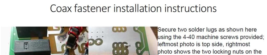
9


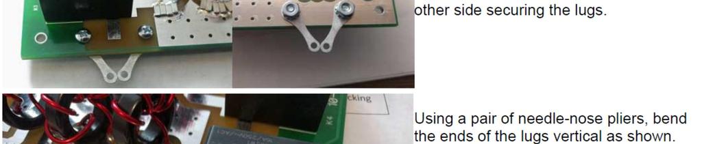
10 Begin construction of your filter by installing the diodes first. This will prevent soldering iron damage to the plastic relay cases (which can get in the way of diode installation if done later). Now it s safe to install the relays.

11 Turn the board over and install the chip capacitors. The 6m segment is on the left, 160m on the right. The example shown below is for the single-pallet configuration; filter segment 4 will have a different pattern installed for the 2-pallet set-up.

12 Wind the inductors and Install them. Jumpers will be used at lpf 2,3,4,5 and 6 when filtering for a single pallet rf deck.

13 When filtering for the 2-pallet rf deck, lpf 2,3 and 6 will have the jumpers, lpf 4 will have an inductor installed at the jumper location, and lpf 5 will have a delay line installed on the foil side of the board (see next photo).

14 For the W6PQL dual-pallet deck, install a 31 rg402 delay line in place of the jumper at lpf5 on the foil side of the board. It can be neatly coiled and secured with cable ties as shown. Note the shield of the cable at both ends is soldered to the ground foil. The RG402 is not supplied in the kit. RG142 may also be used, but is more difficult to work with than RG402.


15
16 Bill of Materials # 16 tinned wire, bare 5 turns ID # 16 tinned wire, bare 6 turns ID #16 magnet wire, 200C, 9" 2 6 turns #16 magnet wire, 200C, 10" 1 7 turns #16 magnet wire, 200C, 11" 2 8 turns #16 magnet wire, 200C, 12" 1 9 turns #16 magnet wire, 200C, 13" 2 10 turns #16 magnet wire, 200C, 15" 2 11 turns #16 magnet wire, 200C, 16" 1 12 turns #16 magnet wire, 200C, 18" 2 14 turns #16 magnet wire, 200C, 20" 2 16 turns #16 magnet wire, 200C, 22" 1 18 turns #16 magnet wire, 200C, 29" 2 18 turns #16 magnet wire, 200C, 30" 1 19 turns 2kv ceramic 330pf pf pf 6 150pf 4 120pf 6 100pf 12 3kv ceramic 68pf 14 47pf 4 39pf 6 33pf 8 22pf 14 15pf 2 10pf 8 G2RL-1-E-12V Relay 10 GF1M Rectifier General Purpose 5 #6 long solder lug k/l x.25 4 PC Board 1 T106-2 toroid core 3 T94-2 toroid core 3 T94-6 toroid core 10
17
The 15 meter section was moved
 2-device amplifier pallets are offered by several makers, and gaining popularity as legal-limit amplifiers with ample headroom; this filter configuration accommodates the higher power levels and elevated
Low Pass Filter (rev 5) for single and 2-Pallet HF Amplifiers The filter sections on this board differ from the web article, and offer some
 for single and 2-Pallet HF Amplifiers The filter sections on this board differ from the web article, and offer some") The filter sections on this board differ from the web article, and offer some improvement in performance, including raising the maximum power handling capacity. The most significant changes were to the
The filter sections on this board differ from the web article, and offer some improvement in performance, including raising the maximum power handling capacity. The most significant changes were to the
Assembly Instructions for the FRB FET FM 70 Watt Amp
 Assembly Instructions for the FRB FET FM 70 Watt Amp 1.) Orient the circuit board with the diagram 2.) Use a narrow chisel tip 25-30 watt soldering iron for assembly 3.) All the small parts are taped onto
Building and Operating: LF Converter An SA612 based LF up-converter from Jackson Harbor Press
 Introduction: Building and Operating: LF Converter An SA612 based LF up-converter from Jackson Harbor Press The frequencies below the broadcast band are covered by few receivers on the market - those that
Assembly Instructions for the 1.5 Watt Amplifier Kit
 Assembly Instructions for the 1.5 Watt Amplifier Kit 1.) All of the small parts are attached to a sheet of paper indicating both their value and id. 2.) Leave the parts affixed to the paper until you are
An Application of Bandpass Filters. Jeff Crawford - K ZR October 15, 2016
 An Application of Bandpass Filters Jeff Crawford - K ZR October 15, 2016 1 Goals for this Discussion: Cover some general filter theory Apply this theory to an amateur radio need SO2R (Single Operator 2
WA3RNC 30 METER CRYSTALPLEXER TRANSMITTER KIT ASSEMBLY INSTRUCTIONS
 WA3RNC 30 METER CRYSTALPLEXER TRANSMITTER KIT ASSEMBLY INSTRUCTIONS Description The WA3RNC 30 Meter Crystalplexer is a low power crystal controlled QRP transmitter offering a significantly improved tuning
SoftRock v6.0 Builder s Notes. May 22, 2006
 SoftRock v6.0 Builder s Notes May 22, 2006 Be sure to use a grounded tip soldering iron in building the v6.0 SoftRock circuit board. The soldering iron needs to have a small tip, (0.05-0.1 inch diameter),
Pacific Antenna 20 and 40M Lightweight Dipole Kit
 Pacific Antenna 20 and 40M Lightweight Dipole Kit Antenna diagram showing configuration and lengths when assembled 7 8 16 9 16 9 Description The Pacific Antenna lightweight dual band dipole kit provides
Using Ferrite Beads Keep RF Out of TV Sets, Telephones, VCR's Burglar Alarms and other Electronic Equipment
 Using Ferrite Beads Keep RF Out of TV Sets, Telephones, VCR's Burglar Alarms and other Electronic Equipment RFI and TVI have been with us for a long time. Now we have microwave ovens, VCR's and many other
Read This Page First
 Pacific Antenna 0 Watt HF Amplifier Kit Manual This is Version 5.5 dated 060505 Read This Page First If you are reading this you know the manuals are always available at QRPKITS.com. If you have questions
G11+ GSDR quick start assembly manual [Part 2]
![G11+ GSDR quick start assembly manual [Part 2]](/thumbs/94/119194661.jpg "G11+ GSDR quick start assembly manual [Part 2]") G11+ GSDR quick start assembly manual [Part 2] January 31, 2012 Ver 1.1 Tasa, YU1LM and Nick, VK2DX Overview G11 quick start assembly manual Part 2 covers assembly of the TX components. There are two chapters
G11+ GSDR quick start assembly manual [Part 2] January 31, 2012 Ver 1.1 Tasa, YU1LM and Nick, VK2DX Overview G11 quick start assembly manual Part 2 covers assembly of the TX components. There are two chapters
Pacific Antenna Low Pass Filter Kit
 Pacific Antenna Low Pass Filter Kit Description Many basic transmitter and/or transceiver designs have minimal filtering on their output and frequently have significant harmonic content in their signals.
HAMTRONICS LPA 2-25R REPEATER POWER AMPLIFIER: ASSEMBLY, INSTALLATION, & MAINTENANCE
 HAMTRONICS LPA 2-25R REPEATER POWER AMPLIFIER: ASSEMBLY, INSTALLATION, & MAINTENANCE GENERAL INFORMATION. The Power Amplifier is a class C device designed to be installed as an integral part of a transmitter
Easy Transmitter. Support ETX_REV5_Manual V2.7 Revised
 Easy Transmitter Introduction The Easy Transmitter kit from qrpkits.com provides a basic, crystal controlled transmitter with VXO tuning to provide a small tuning range around the crystal frequency. It
Pacific Antenna 10 Watt HF Amplifier Kit
 Pacific Antenna 0 Watt HF Amplifier Kit Description Our 0 watt Linear, HF amplifier kit is designed to increase the power output of low power transmitters. Gives up to 5dB gain and includes an input attenuator
Transmission Line Signal Sampling By Don Steinbach, AE6PM
 Transmission Line Signal Sampling By Don Steinbach, AE6PM When I was finalizing the mechanical layout of my remotely-operated 3-position coaxial antenna switch (Fig. 1), I wanted to include a way to bring
10 2 2,13,15,16,46 27, non-inductive ,26,
 HANDS-ON RADIO PARTS LIST (Thanks, John AF4WM and Steve AD7KR) Updated through Experiment 129 Quantities assume all parts available for re-use MAX QTY EXPERIMENT NOTES 1/4 WATT RESISTOR (All values are
Read This Page First
 Read This Page First If you are reading this you know the manuals are always available at QRPKITS.com. If you have questions contact qrpkits.com@gmail.com There is no need to print out the whole assembly
Dual Band Filter Assembly Manual
 Dual Band Filter Assembly Manual 12 January 2018 Rev D Version Theory of Operation: The purpose of a Bandpass Filter is to filter out or reject all unwanted signals. The original KN-Q7A Receive Filter
A Transmatch for Balanced or Unbalanced Lines
 A Transmatch for Balanced or Unbalanced Lines Most modern transmitters are designed to operate into loads of approximately 50 Ω. Solid-state transmitters produce progressively lower output power as the
Building the Sawdust Regenerative Receiver
 Building the Sawdust Regenerative Receiver Introduction The Sawdust is a super regenerative receiver using the basic Armstrong design architecture. The receiver uses one toroidal transformer to provide
KN-Q10 Assembly Manual
 KN-Q10 Assembly Manual Translated by Adam Rong, BD6CR/4 with permission from Ke Shi, BA6BF Edited by Stephen, VK2RH Revision B, Oct 14, 2010 Thank you for purchasing the KN-Q10 4 Band SSB/CW Dual Mode
DEM Part Number L144-28INTCK 144 MHz Transverter Kit and complete kit
 DEM Part Number L144-28INTCK 144 MHz Transverter Kit and complete kit Power Out: Noise Figure and Gain: DC Power Requirement: 50 mw linear minimum 3.5 db NF nominal, 5 dbg maximum 12-15.5 VDC, 13.8 nominal
ALX-SSB 5 Band Filter Assembly Manual 19 November 2018
 ALX-SSB 5 Band Filter Assembly Manual 19 November 2018 Contents Theory of Operation:... 1 Figure 1... 2 Parts Included:... 4 Board Overview:... 5 Figure 2... 5 Figure 3... 5 Board Assembly:... 6 Cable
SoftRock v5.0 Builder s Notes. December 12, Building a QSD Kit
 SoftRock v5.0 Builder s Notes December 12, 2005 Building a QSD Kit Be sure to use a grounded tip soldering iron in building the QSD board. The soldering iron needs to have a small tip, (0.05-0.1 inch diameter),
QRPme.com Kits. Tx/Tuna Topper. Assembly and Operation Guide. Kits for the QRP and Electronics Hobbyist. Heatsink left off for better assembly viewing
 QRPme.com Kits Kits for the QRP and Electronics Hobbyist Tx/Tuna Topper Heatsink left off for better assembly viewing QRMme.com Kits Tx/Tuna Topper Contents Figures and Illustrations...............................
Modifying The Heath HA-14 For 6 Meters Greg Chartrand - W7MY 4/22/07
 Introduction The Heathkit HA-14 was one of the few electron tube linear amplifiers intended for mobile use but few were purchased with the 12 volt mobile power supply. Most hams bought the HA-14 for base
APPLICATION NOTE. System Design for RF Immunity
 APPLICATION NOTE System Design for RF Immunity Audio Codec Application Note Rev1.0 Page 1 of 6 March 2008 With the growth of the portable electronic devices industry, radiated RF fields and potential interference
SPECIFICATIONS: Subcarrier Frequency 5.5MHz adjustable, FM Modulated +/- 50KHz. 2nd 11MHz >40dB down from 5.5MHz
 Mini-kits AUDIO / SUBCARRIER KIT EME75 Version4 SPECIFICATIONS: Subcarrier Frequency 5.5MHz adjustable, FM Modulated +/- 50KHz Subcarrier Output 1.5v p-p Output @ 5.5MHz DESCRIPTION & FEATURES: The Notes
Step by Step Building PJ meter ARDF Receiver Kit. CRKITS.COM August 5, 2013
 Step by Step Building PJ-80 80-meter ARDF Receiver Kit CRKITS.COM August 5, 2013 What is ARDF? ARDF is the abbreviation of Amateur Radio Direction Finding, or so called Fox Hunting. If you are looking
ARNSW Balun Day. Balun construction
 ARNSW Balun Day Balun construction Typical Baluns All built from locally available components. Balun uses Most baluns are used to match the 50Ω output of a transceiver to an antenna. A centre fed dipole
Modifying the Larcan VHF Lo/Hi 1.5KW Amplifier for 144MHz. by Corey Abercrombie, N4NGZ May 2015
 Modifying the Larcan VHF Lo/Hi 1.5KW Amplifier for 144MHz. by Corey Abercrombie, N4NGZ May 2015 This document details the steps I took to modify the Larcan VHF Lo/Hi 1.5KW Amplifier for 144MHz. With a
Building the Sawdust Regenerative Receiver
 Building the Sawdust Regenerative Receiver Introduction The Sawdust is a super regenerative receiver using the basic Armstrong design architecture. The receiver uses one toroidal transformer to provide
Pacific Antenna 20 and 40M Lightweight Dipole Kit
 Pacific Antenna 20 and 40M Lightweight Dipole Kit Diagram showing configuration and approximate lengths 8 6 16 9 16 9 8 6 Description The Pacific Antenna lightweight dual band, trap dipole kit provides
TS-930: Installing the Inrad Roofing Filter Mod
 TS-930: Installing the Inrad Roofing Filter Mod The TS-930 roofing filter mod consists of a 6 pole, 4 to 5 khz wide filter followed by a high dynamic range, feedback amplifier. The amplifier provides enough
Antenna Matching Within an Enclosure Part II: Practical Techniques and Guidelines
 Antenna Matching Within an Enclosure Part II: Practical Techniques and Guidelines By Johnny Lienau, RF Engineer June 2012 Antenna selection and placement can be a difficult task, and the challenges of
SoftRock v6.0 Builder s Notes. April 6, 2006
 SoftRock v6.0 Builder s Notes April 6, 006 Be sure to use a grounded tip soldering iron in building the v6.0 SoftRock circuit board. The soldering iron needs to have a small tip, (0.05-0. inch diameter),
A short, off-center fed dipole for 40 m and 20 m by Daniel Marks, KW4TI
 A short, off-center fed dipole for 40 m and 20 m by Daniel Marks, KW4TI Version 2017-Nov-7 Abstract: This antenna is a 20 to 25 foot long (6.0 m to 7.6 m) off-center fed dipole antenna for the 20 m and
HF SuperPacker Pro 100W Amp Low Pass Filter Module LPF-100 R3B. Construction Manual for Model LPF-100 R3B June 22, 2013
 HF SuperPacker Pro W Amp Low Pass Filter Module LPF- RB Construction Manual for Model LPF- RB June, LPF RB TOP LPF RB BOTTOM The LPF- RB design is electrically the same as RA but has been changed for improved
Compact 50 MHz High Power Solid State Amplifier using MRFE6VP61K25H
 Compact 50 MHz High Power Solid State Amplifier using MRFE6VP61K25H By F5FLN Michel ROUSSELET and F1TE Lucien SERRANO, F6BKI Jacques RAMBAUD November 2011 Rev1 This Article deals with RF amplifier design
20 meter bandstop filter notes
 1 Introduction 20 meter bandstop filter notes Kevin E. Schmidt, W9CF 6510 S. Roosevelt St. Tempe, AZ 85283 USA A shorted half-wavelength stub cut for 20 meters acts as a bandstop filter for 10 and 20 meters,
LC31L-BAT Link Coupler
 Instruction Manual For the LC31L-BAT Link Coupler 09 March 2018 2012-2018 by Ralph Hartwell Spectrotek Services All rights reserved 2 RADIO FREQUENCY WARNING NOTICE If the LC31L-BAT is installed incorrectly
Pacific Antenna Easy Transmitter Kit
 Pacific Antenna Easy Transmitter Kit Introduction The Easy Transmitter kit from qrpkits.com provides a crystal controlled transmitter with VXO tuning. The circuit consists of a N3904 based crystal oscillator
Practical Tricks with Transformers. Larry Weinstein K0NA
 Practical Tricks with Transformers Larry Weinstein K0NA Practical Tricks with Transformers Quick review of inductance and magnetics Switching inductive loads How many voltages can we get out of a $10 Home
QRP to 30-35W HF Packer Amp minihfpa Edition. Beat the downturn in HF conditions! Make your SOTA/NPOTA/WWF activations a success every time!
 QRP to 30-35W HF Packer Amp minihfpa Edition Beat the downturn in HF conditions! Make your SOTA/NPOTA/WWF activations a success every time! The minihfpa is a 5th generation HF PackerAmp optimized for your
G6ALU 20W FET PA Construction Information
 G6ALU 20W FET PA Construction Information The requirement This amplifier was designed specifically to complement the Pic-A-Star transceiver developed by Peter Rhodes G3XJP. From the band pass filter an
Pacific Antenna 20 and 40M Lightweight Dipole Kit
 Pacific Antenna 20 and 40M Lightweight Dipole Kit Diagram showing configuration and approximate lengths 8 3 16 9 16 9 8 3 Description The Pacific Antenna lightweight dual band, trap dipole kit provides
SSPA Construction Techniques
 SSPA Construction Techniques 6m, 2m, 222MHz, 70cm 23cm and above 1.8 54MHz digressed a bit at mentioning 1.8-54, didn t I? September 2016 Austin BBQ, 2016 1 But Wait Let s examine how to build that SSPA
Some hints/tips on how to assemble nice COAX TRAPS!
 Some hints/tips on how to assemble nice COAX TRAPS! Before we start to assemble our traps, here some general info as introduction : Coax traps are cheap, easy to assemble in a reproducible manner, very
Properties of Inductor and Applications
 LABORATORY Experiment 3 Properties of Inductor and Applications 1. Objectives To investigate the properties of inductor for different types of magnetic material To calculate the resonant frequency of a
LPF-9B Nine band low pass filter module kit ( meters)
") LPF-9B Nine band low pass filter module kit (80-60-40-30-20-17-15-12-10 meters) Assembly manual Last update: March 1, 2018 ea3gcy@gmail.com Most recent updates and news at: www.ea3gcy.com Thanks for constructing
LPF-9B Nine band low pass filter module kit (80-60-40-30-20-17-15-12-10 meters) Assembly manual Last update: March 1, 2018 ea3gcy@gmail.com Most recent updates and news at: www.ea3gcy.com Thanks for constructing
End Fed Half Wave Antenna Coupler
 End Fed Half Wave Antenna Coupler The finished End Fed Half Wave antenna coupler. Centre fed half wave dipoles make great, simple and effective antennas for the HF bands. Sometimes however, the centre
Low-Pass Filter Designs
 Low-Pass Filter Designs es: These filters have been designed to allow WSPRlite units to meet regulatory requirements for spurious emissions. The filters are seven-element Chebyshev designs. The filters
Build this Direct Digital Synthesizer "Development Kit" By: Diz Gentzow, W8DIZ
 Build this Direct Digital Synthesizer "Development Kit" By: Diz Gentzow, W8DIZ A great tutorial for adding a keypad to the DDS Kit by Bruce, W8BH This manual has been prepared to be read directly on screen.
Pacific Antenna Easy TR Switch
 Pacific Antenna Easy TR Switch Kit Description The Easy TR Switch is an RF sensing circuit with a double pole double throw relay that can be used to automatically switch an antenna between a separate receiver
C.M.HOWES COMMUNICATIONS CTU150 Instructions
 CTU150 Instructions The HOWES CTU150 is an antenna matching unit for use with shortwave transmitters and receivers. A novel constructional method is used - all parts being mounted on a Printed Circuit
QRPme.com Kits. Tx/Tuna Topper. Assembly and Operation Guide. Kits for the QRP and Electronics Hobbyist. Heatsink left off for better assembly viewing
 QRPme.com Kits Kits for the QRP and Electronics Hobbyist Tx/Tuna Topper Heatsink left off for better assembly viewing Contents Figures and Illustrations............................... 3 Jumpers............................................
Instructions MODIFICATION KIT MODEL SBM - 1O2-1 INTRODUCTION PARTS LIST FOR THE
 Instructions FOR THE MODIFICATION KIT MODEL SBM - 1O2-1 INTRODUCTION This modification Kit applies to the following Heath Transceivers: 1. All Models HW-100, SB-100, SB-101 and SB-101W. 2. Any Model SB-102
VCO Design Project ECE218B Winter 2011
 VCO Design Project ECE218B Winter 2011 Report due 2/18/2011 VCO DESIGN GOALS. Design, build, and test a voltage-controlled oscillator (VCO). 1. Design VCO for highest center frequency (< 400 MHz). 2. At
About LC Meter This is one of the most accurate and simplest LC inductance / capacitance Meters that one can find, yet one that you can easily build y
 Home Electronic Store Electronic Blog Electronic Schematics Tutorials Downloads Lin Very Accurate LC Meter based on PIC16F84A IC. LC Meter Part's List: 2x 1K 2x 6.8K 1x 47K 3x 100K 1x 10K POT 2x 10pF 1x
V6.2 SoftRock Lite Builder s Notes. November 17, 2006
 V6.2 SoftRock Lite Builder s Notes November 17, 2006 Be sure to use a grounded tip soldering iron in building the v6.2 SoftRock circuit board. The soldering iron needs to have a small tip, (0.05-0.1 inch
Homebrew and Experimenters Group HF Inductance Bridge (Compiled by VK2TOX)
") Homebrew and Experimenters Group HF Inductance Bridge (Compiled by VK2TOX) There are a number of ways to measure inductances used in construction of RF equipment. One of the most versatile ways is with
Homebrew and Experimenters Group HF Inductance Bridge (Compiled by VK2TOX) There are a number of ways to measure inductances used in construction of RF equipment. One of the most versatile ways is with
Entry Level Assessment Blueprint Electronics Technology
 Blueprint Test Code: 4135 / Version: 01 Specific Competencies and Skills Tested in this Assessment: Safety Practices Demonstrate safe working procedures Explain the purpose of OSHA and how it promotes
Hendricks QRP Kits The Twofer Rev
 Hendricks QRP Kits The Twofer Rev 1 11-15-06 1. Description The Twofer is a classic QRP transmitter that s easy to assemble and operate. It uses a JFET VXO (variable crystal oscillator), driver stage and
12kHz LIF Converter V2.43 9Mhz version
 12kHz LIF Converter V2.43 9Mhz version Please Note: This document supersedes all previously released documents and drawings on the LIF subject. This is the latest and most up-to-date document at this time.
tuning and RF circuits wireless automotive inductors inductance (L). Now frequencies
. Now frequencies") RF Chip Inductor Applications December 2011 Application Note RF chip are an integral part of many tuning and filtering circuits and are mainly used in the RF circuits in electronics systems. With a small
RF Chip Inductor Applications December 2011 Application Note RF chip are an integral part of many tuning and filtering circuits and are mainly used in the RF circuits in electronics systems. With a small
A 100-Watt Transmitter Using a Pair of VT1625s
 12/16/2007 6:00 PM VT1625 100 Watt Transmitter A 100-Watt Transmitter Using a Pair of VT1625s FIG. 10.6 A 100-watt transmitter for five bands, using salvaged TV power transformer and surplus 1625 amplifier
Pacific Antenna Easy SWR Indicator Kit
 Pacific Antenna Easy SWR Indicator Kit Description Monitoring the match of an antenna to your transmitter or adjusting an antenna tuner for best match requires an indicator of the reflected power as an
Pacific Antenna - Easy TR Switch
 Pacific Antenna - Easy TR Switch Kit Description The Easy TR Switch is an RF sensing switch that can be used to switch an antenna between a receiver and transmitter. It also has a second switched pair
S-Pixie QRP Kit. Student Manual. Revision V 1-0
 S-Pixie QRP Kit Student Manual Revision V 1-0 Introduction The Pixie 2 is a small, versatile radio transceiver that is very popular with QRP (low power) amateur radio operators the world over. It reflects
Electromagnetic Compatibility
 Electromagnetic Compatibility Introduction to EMC International Standards Measurement Setups Emissions Applications for Switch-Mode Power Supplies Filters 1 What is EMC? A system is electromagnetic compatible
CONSTRUCTION. Refer to schematic and component location diagrams during assembly
 HAMTRONICS VHF RECEIVING CONVERTERS CONSTRUCTION, ALIGNMENT, & INSTALLATION INSTRUCTIONS GENERAL DESCRIPTION. The CA( ) series of VHF Receiving Converter modules are designed to amplify and convert the
Rx antennas at IV3PRK: the 4-Square Rx Vertical Array
 Rx antennas at IV3PRK: the 4-Square Rx Vertical Array Part 2: putting all stuff together and construction details Calculating the cable lengths by Pierluigi Luis Mansutti IV3PRK The most difficult choice,
Ameritron ALS-600 Retrofit ALS-600-LPF Assembly Manual
 Ameritron ALS-600 Retrofit ALS-600-LPF Assembly Manual FEATURES Automatic band change based on TX frequency. PIN diode QSK RX/TX switch. Temperature controlled FAN for quiet operation. RS-232 serial port
160- and 80-Meter Matching Networks for your 43-foot Vertical Phil Salas AD5X
 160- and 80-Meter Matching Networks for your 43-foot Vertical Phil Salas AD5X 43-foot verticals have become popular as they can be self supporting, are not too obtrusive, and have higher radiation resistance
HF Amateur SSB Receiver
 HF Amateur SSB Receiver PCB Set for radio club project http://rhelectronics.net PCB for DIY HF Amateur SSB Receiver 20M The receiver is a simple syperheterodyne type with quartz crystal filter. The circuit
Connecting the FCC-2 to the Hendricks DC Kits Bob Okas, W3CD
 Connecting the FCC-2 to the Hendricks DC Kits Bob Okas, W3CD This is an application note that describes how you can connect the NorCal FCC-1/2 combination to the DC kits. It involves a few extra components
C99-20LL System Cable P/N 40935G-06 INSTALLATION SHEET
 C99-20LL System Cable P/N 40935G-06 INSTALLATION SHEET The C99-20LL Interface cable connects a Universal Gateway Wireless System with the David Clark Series 9500 Marine Intercom System, and allows the
Name. Part A (25 Points) Complete on Blackboard. A. (25 Pts) Part B (75 Points) 1. (12 Pts) 2. (12 Pts) 3. (10 Pts) 4. (8 Pts) 5. (11 Pts) 6.
 Complete on Blackboard. A. (25 Pts) Part B (75 Points) 1. (12 Pts) 2. (12 Pts) 3. (10 Pts) 4. (8 Pts) 5. (11 Pts) 6.") Name Part A (25 Points) Complete on Blackboard A. (25 Pts) Part B (75 Points) 1. (12 Pts) 2. (12 Pts) 3. (10 Pts) 4. (8 Pts) 5. (11 Pts) 6. (6 Pts) 7. (13 Pts) 8. (3 Pts) Total Annotate the circuit diagrams
Name Part A (25 Points) Complete on Blackboard A. (25 Pts) Part B (75 Points) 1. (12 Pts) 2. (12 Pts) 3. (10 Pts) 4. (8 Pts) 5. (11 Pts) 6. (6 Pts) 7. (13 Pts) 8. (3 Pts) Total Annotate the circuit diagrams
SD4933. HF/VHF/UHF RF power N-channel MOSFET. Features. Description
 HF/VHF/UHF RF power N-channel MOSFET Features Datasheet - production data Improved ruggedness V (BR)DSS > 200 V Excellent thermal stability 20:1 all phases load mismatch capability P OUT = 300 W min. with
EH-20 20m antenna. By VE3RGW
 EH-20 20m antenna By VE3RGW Equivalent circuit of EH-20 antenna system. Upper cylinder Lower cylinder Phasing coil Common mode radiator Tune coil RF choke or 14MHz trap 50ohm coaxial cable 0-150pF (case
G3EJS 2-Tuner. Having recently bought an FT-817, and immediately missing the internal tuner my IC-703 has, I started looking for an answer.
 G3EJS 2-Tuner Having recently bought an FT-817, and immediately missing the internal tuner my IC-703 has, I started looking for an answer. There are tuners around, but everything I saw was just about as
How to use your antenna tuner.
 How to use your antenna tuner. There's more to it than what is in your manual or on most how to do it websites! http://www.arrl.org/tis/info/ant-tuner-op.html Here is a neat site with a "T" network simulator.
Technical Info Doc: Galileo2 A simple Direct Conversion Receiver for 20.1MHZ
 Fox Delta Amateur Radio Projects & Kits FD Galileo2 Technical Info Doc: Galileo2 A simple Direct Conversion Receiver for 20.1MHZ This Project is dedicated to our beloved scientist Galileo: Galileo was
Array Solutions Four Square Array Manual and User s Guide
 Array Solutions Four Square Array Manual and User s Guide Array Solutions Four Square Array Pattern Steering System Congratulations! You have selected one of the finest phased array steering systems made.
Electrical Fundamentals and Basic Components Chapters T2, T3, G4
 Electrical Fundamentals and Basic Components Chapters T2, T3, G4 Some Basic Math, Electrical Fundamentals, AC Power, The Basics of Basic Components, A Little More Component Detail, Reactance and Impedance
IC-765: Installing the Inrad Roofing Filter Mod
 IC-765: Installing the Inrad Roofing Filter Mod The Icom IC-765 roofing filter mod consists of a 6-pole, 4 khz wide filter followed by a high dynamic range, feedback amplifier. The amplifier provides enough
Spiderbeam Balun Construction Guide
 BALUN CONSTRUCTION GUIDE Ver. 1.0 1 The components of the Balun Kit are in a plastic bag. Most of the components are inside the plastic case of the balun. The aluminum U-profile and the RG-142 Teflon Coax
50 V moisture resistant DMOS transistor for ISM applications. Features. Description. Table 1. Device summary
 50 V moisture resistant DMOS transistor for ISM applications Features Datasheet - production data M177MR Epoxy sealed Figure 1. Pin connection 3 4 1 2 5 Improved ruggedness V (BR)DSS > 200 V Excellent
JC-5 4KW PEP, 1KW RMS AUTO ANTENNA COUPLER
 JC-5 4KW PEP, 1KW RMS AUTO ANTENNA COUPLER 1) DIRECTLY CONTROLLED BY ICOM, ALINCO & KENWOOD. 2) INDEPENDENT CAPACITOR INPUT AND OUTPUT BLOCKS! 3) 3 mm COIL WIRE & INTERNAL FAN FOR THE BIG COILS! 4) DIPPED
Pacific Antenna SLT+ Switched Long wire Tuner
 Pacific Antenna SLT+ Switched Long wire Tuner The SLT+ is designed to match the high impedance load of an end feed, half wave antenna wire to a 50 ohm transmitter using manually switched inductors and
Electro-Magnetic Interference and Electro-Magnetic Compatibility (EMI/EMC)
") INTROUCTION Manufacturers of electrical and electronic equipment regularly submit their products for EMI/EMC testing to ensure regulations on electromagnetic compatibility are met. Inevitably, some equipment
INTROUCTION Manufacturers of electrical and electronic equipment regularly submit their products for EMI/EMC testing to ensure regulations on electromagnetic compatibility are met. Inevitably, some equipment
QRPme.com Kits. Tx/Tuna Topper. Assembly and Operation Guide. Kits for the QRP and Electronics Hobbyist. Heatsink left off for better assembly viewing
 QRPme.com Kits Kits for the QRP and Electronics Hobbyist Tx/Tuna Topper Heatsink left off for better assembly viewing Contents Figures and Illustrations............................... 3 Jumpers............................................
1) Transmission Line Transformer a. First appeared on the scene in 1944 in a paper by George Guanella as a transmission line transformer, the 1:1
 Transmission Line Transformer a. First appeared on the scene in 1944 in a paper by George Guanella as a transmission line transformer, the 1:1") 1) Transmission Line Transformer a. First appeared on the scene in 1944 in a paper by George Guanella as a transmission line transformer, the 1:1 Guanella Balun is the basic building Balun building block.
1) Transmission Line Transformer a. First appeared on the scene in 1944 in a paper by George Guanella as a transmission line transformer, the 1:1 Guanella Balun is the basic building Balun building block.
Lesson 3: Electronics & Circuits
 Lesson 3: Electronics & Circuits Preparation for Amateur Radio Technician Class Exam Topics Review Ohm s Law Energy & Power Circuits Inductors & Inductance Capacitors & Capacitance Analog vs Digital Exam
Ferrites for High Frequency Noise Suppression Chapter 9
 TMPST ngineering and Hardware Design Dr. Bruce C. abrielson, NC 1998 Ferrites for High Frequency Noise Suppression Chapter 9 Introduction The drive for higher speed devices and the proliferation of widespread
Read This Page First
 Read This Page First If you are reading this you know the manuals are always available at QRPKITS.com. This is version 8.0 of the manual dated 4/27/2016. There is no need to print out the whole assembly
MFJ-203 Bandswitched Dip Meter
 MFJ-203 Bandswitched Dip Meter Thank you for purchasing the MFJ-203 Bandswitched Dip Meter. The MFJ-203 Bandswitched Dip Meter is a solid state bandswitched adaptation of the traditional grid dip meter.
Using Ferrites for High Frequency Noise Suppression
 Using Ferrites for High Frequency Noise Suppression Bruce C. abrielson, PhD Security ngineering Services PO Box 550, Chesapeake Beach, Maryland 20732 Introduction The drive for higher speed devices and