The Tellun Corporation. TLN-861 Dunsel. User Guide, Rev Scott Juskiw The Tellun Corporation
|
|
|
- Brett Scott
- 5 years ago
- Views:
Transcription
1 The Tellun Corporation TLN-861 Dunsel User Guide, Rev. 1.0 Scott Juskiw The Tellun Corporation TLN-861 User Guide Revision 1.0 August 31, 2006
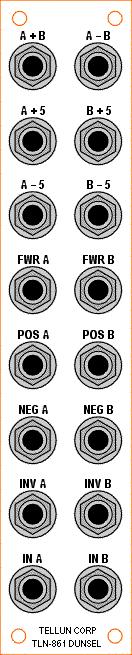
2 1. Introduction The TLN-861 Dunsel is a collection of utility circuits for a modular synthesizer. These circuits are all quite simple and can all be found in Jung s Op-Amp cookbook. The Dunsel has two channels, A and B, with one input for each channel and the following independent outputs: INV: an inverted version of the input signal. NEG: the negative portion of the input signal. For voltages less than zero, the output follows the input. For voltages greater than zero, the output is zero. POS: the positive portion of the input signal. For voltages greater than zero, the output follows the input. For voltages less than zero, the output is zero. FWR: a full wave rectified version of the input signal: the absolute value of the input signal. 5V: the input signal offset down by 5 volts. +5V: the input signal offset up by 5 volts. The Dunsel also provides the following two dependent outputs: A+B: the sum of the A and B input signals. A-B: the difference of the A and B input signals. All outputs are capable of driving an oscillator s V/OCT input without any voltage drop across the output stage. 2. Circuit Description Page 1 of the schematic shows all the circuitry for the A channel. The input signal is buffered by U1a and provides a high input impedance so as not to load down whatever module is driving the input. The output from this buffer (A+) is a non-inverted version of the input and drives a number of the other circuits. The A+ signal is inverted by U1b, to create the A- signal, which also drives a number of the other circuits. U2b provides the inverted A output (INV A). C31 is used to keep spurious oscillations in check when using long cables. Note that R8, the output protection resistor, is included in the feedback loop with R7. This prevents a voltage drop in the output stage when fed to the V/OCT input of an oscillator. This output stage is used many times in the Dunsel. The A+ signal is fed to U3a where it is half wave rectified and inverted (the A HW+ signal). This signal is then inverted by U3b to provide the positive A output (POS A). U4a performs a similar function on the inverted version of the input signal. The output from this stage (A HW-) is already the correct polarity so it is simply buffered by U4b to provide the negative A output (NEG A). This output stage, using C27, C28, R25, and R26, can be used to drive the V/OCT input of an oscillator without incurring a voltage drop at the output. 1
3 The A HW+ and A HW- signals are summed and inverted by U2a to create the full wave rectified signal (FWR A). The offset signals are provided by U5a (A+5) and U5b (A-5) by simply adding an offset to the A- signal and then inverting. Page 2 of the schematic shows all the circuitry for the B channel which is identical to that used for the A channel. Page 3 of the schematic shows the circuits for the A+B and A-B outputs. These are simply inverting summers with the appropriate inputs applied; the A-, B+, and B- signals are shown on pages 1 and 2 of the schematic. 3. Construction Tips Use 1% resistors wherever they are shown in the schematic. Use coax cable for the jack connections. The TLN-861 can be used with audio signals, so it s a good idea to use coax cable to keep noise out of the circuit. For coax connections between the panel jacks and PCBs, connect the coax shield to ground at both ends of the coax (at the ground lug of the jack and to the square hole on the PCB). When making coax connections between two PCBs, connect the coax shield to ground at one end only. Clip the coax shield from the other end and cover with a piece of heat shrink tubing to prevent any stray strands from coming into contact with anything. At this clipped end, connect only the core (inside) conductor. signal RG174/U heat shrink tubing signal ground 4. Modifications You can substitute LT1013 op-amps if you want the best DC performance. But LT1013s are slow for audio signals. You can substitute OP275 op-amps if you want the best audio performance, but they have poorer DC performance. I used TL072 op-amps throughout since they are a good compromise between the LT1013 and OP275 and give good results for both DC and audio signals. 2
4 5. Building the Dunsel with MUUBs Be sure to check out the construction pictures on the website. Most of what I try to describe below can best be understood just by looking at the pictures. You ll need four MUUB-4 and three MUUB-2 to build the TLN-861. These boards are designated: 1A, 2A, 3A, 1B, 2B, 3B, and 4. If you look at the pictures on the website, you ll see the seven boards stacked on the Stooge brackets in the following manner: Board 4 Board 1B Board 2B Board 3A Board 3B Board 1A Board 2A Boards 2B, 3B, and 2A are on the first layer, nearest the Stooge flat plate modular bracket. Boards 1B, 3A, and 1A are on the second layer (mounted above the first layer). Board 4 is mounted above board 3A on the third layer. I built the TLN-861 with Stooge modular brackets and a Stooge compatible 1U wide panel (a prototype panel made from plexiglass). Prepare your panel and Stooge brackets before you do any soldering. Get all the mechanical issues dealt with first. You ll need two of the Stooge 2 jack modular bracket and one of the Stooge flat plate modular bracket. Once you get the three bracket parts bolted together (use ¼ #6 screws) and attached to the panel, you should have enough space to mount the first layer of boards (2B, 3B, and 2A) to the bracket using ¼ spacers and #6 screws. Make sure you leave enough space for the Switchcraft 112A jacks so that they don t interfere with the MUUB-4 boards. Use 3/8 spacers to mount the second layer of boards (1B, 3A, and 1A) above the first layer of boards. Use 3/8 spacers to mount board 4 above board 3A on the third layer. I recommend getting some ¼ and 3/8 spacers, a wide selection of #6 screws in different lengths (from ¼ to 1-1/4 ), and some extra #6 nuts. Before beginning the soldering, note the following labeling conventions used in this document for these components. 1. Diodes: banded end is cathode, other end is anode. 3
5 5.1. Building Board 1A (MUUB-4) Use the following table to place components from the TLN-861 schematic onto a MUUB-4 board. For short s, use a scrap resistor lead. For longer s, use a piece of #22 wire. Note that R1 must be placed in an upright position so that it will fit into the holes. Check the website pictures. Schematic MUUB-4 Location (board 1A) R1-10K CA2, middle and bottom holes, resistor stands upright R2-470K RA6 R3-100K RB1 R4-100K RB9 R5-49K9 RB13 R6-100K RD1 R7-100K RD10 R8-100 RD14 R9-49K9 RD13 R10-100K RC1 R11-100K RC2 R12-100K RC10 R RC14 R14-33K RC13 C1-100N C5 (bypass cap for U1) C2-100N C6 (bypass cap for U1) C3-100N C3 (bypass cap for U2) C4-100N C4 (bypass cap for U2) C23-22M C1 (power supply bypass cap) C25-22M C2 (power supply bypass cap) C31-33P CD3, top and bottom holes C32-33P CC3, top and bottom holes RA1 RA5 RA14 CA1, middle and bottom holes CA3, middle and bottom holes RB7 RB8 RB14 CB4 top hole to CB2 middle hole CB1, middle and top holes TB2, middle to ground hole (at immediate left) CC1, middle and bottom holes TC2, middle to ground hole (at immediate left) CD1, middle and top holes TD2, middle to ground hole (at immediate left) This board contains two electrolytic caps for power supply bypassing, but it does not include the two ferrite beads nor the MTA-156 connector (those items will be installed on board 1B). 4
6 Two additional wires are required. Use the following table to make these connections. The wire length and colour (as seen in the website pictures) is also given. From To Length (inches) RA3 (right hole) JD1 (right hole) 3 (blue) RA2 (right hole) JB1 (right hole) 1.5 (blue) Note that a number of s are used to create additional outputs for U1a and U1b from unused pads. These additional outputs are needed so that the A+ and A- signals can be fed to other parts of the circuit Building Board 1B (MUUB-4) Use the following table to place components from the TLN-861 schematic onto a MUUB-4 board. For short s, use a scrap resistor lead. For longer s, use a piece of #22 wire. Note that R37 must be placed in an upright position so that it will fit into the holes. Check the website pictures. Schematic MUUB-4 Location (board 1B) R37-10K CA2, middle and bottom holes, resistor stands upright R38-470K RA6 R39-100K RB1 R40-100K RB9 R41-49K9 RB13 R42-100K RD1 R43-100K RD10 R RD14 R45-49K9 RD13 R46-100K RC1 R47-100K RC2 R48-100K RC10 R RC14 R50-33K RC13 C11-100N C5 (bypass cap for U6) C12-100N C6 (bypass cap for U6) C13-100N C3 (bypass cap for U7) C14-100N C4 (bypass cap for U7) C24-22M C1 (power supply bypass cap) C26-22M C2 (power supply bypass cap) C36-33P CD3, top and bottom holes C37-33P CC3, top and bottom holes L1 L1 (ferrite bead) L2 L2 (ferrite bead) JP1 MTA-156 power connector RA1 RA5 RA14 CA1, middle and bottom holes CA3, middle and bottom holes RB7 RB8 5
7 RB14 CB4 top hole to CB2 middle hole CB1, middle and top holes TB2, middle to ground hole (at immediate left) CC1, middle and bottom holes TC2, middle to ground hole (at immediate left) CD1, middle and top holes TD2, middle to ground hole (at immediate left) Two additional wires are required. Use the following table to make these connections. The wire length and colour (as seen in the website pictures) is also given From To Length (inches) RA3 (right hole) JD1 (right hole) 3 (blue) RA2 (right hole) JB1 (right hole) 1.5 (blue) Note that a number of s are used to create additional outputs for U6a and U6b from unused pads. These additional outputs are needed so that the B+ and B- signals can be fed to other parts of the circuit Building Board 2A (MUUB-4) Use the following table to place components from the TLN-861 schematic onto a MUUB-4 board. For short s, use a scrap resistor lead. For longer s, use a piece of #22 wire. Check the website pictures. Schematic MUUB-4 Location (board 2A) R15-100K RA1 R16-100K RA10 R17-49K9 RA13 R18-100K RB1 R19-100K RB10 R RB14 R21-49K9 RB13 R22-100K RC1 R23-100K RC10 R24-49K9 RC13 R RD14 R26-47K RD10 D RA9 (cathode to left) D RA14 (cathode to right) D RC9 (cathode to left) D RC14 (cathode to right) C5-100N C5 (bypass cap for U3) C6-100N C6 (bypass cap for U3) C7-100N C3 (bypass cap for U4) C8-100N C4 (bypass cap for U4) C27-1N CD3, top and bottom holes C28-1N CD4, top and bottom holes C33-33P CB3, top and bottom holes CA1, middle and bottom holes 6
8 TA2, middle to ground hole (at immediate left) CB1, middle and top holes TB2, middle to ground hole (at immediate left) CC1, middle and bottom holes TC2, middle to ground hole (at immediate left) Two additional wires are required. Use the following table to make these connections. The wire length and colour (as seen in the website pictures) is also given. From To Length (inches) CA4 (bottom hole) JB1 (right hole) 2 (blue) CC4 (bottom hole) RD12 (left hole) 2 (blue) 5.4. Building Board 2B (MUUB-4) Use the following table to place components from the TLN-861 schematic onto a MUUB-4 board. For short s, use a scrap resistor lead. For longer s, use a piece of #22 wire. Check the website pictures. Schematic MUUB-4 Location (board 2B) R51-100K RA1 R52-100K RA10 R53-49K9 RA13 R54-100K RB1 R55-100K RB10 R RB14 R57-49K9 RB13 R58-100K RC1 R59-100K RC10 R60-49K9 RC13 R RD14 R62-47K RD10 D RA9 (cathode to left) D RA14 (cathode to right) D RC9 (cathode to left) D RC14 (cathode to right) C15-100N C5 (bypass cap for U8) C16-100N C6 (bypass cap for U8) C17-100N C3 (bypass cap for U9) C18-100N C4 (bypass cap for U9) C29-1N CD3, top and bottom holes C30-1N CD4, top and bottom holes C38-33P CB3, top and bottom holes CA1, middle and bottom holes TA2, middle to ground hole (at immediate left) CB1, middle and top holes TB2, middle to ground hole (at immediate left) CC1, middle and bottom holes TC2, middle to ground hole (at immediate left) 7
9 Two additional wires are required. Use the following table to make these connections. The wire length and colour (as seen in the website pictures) is also given. From To Length (inches) CA4 (bottom hole) JB1 (right hole) 2 (blue) CC4 (bottom hole) RD12 (left hole) 2 (blue) 5.5. Building Board 3A (MUUB-2) Use the following table to place components from the TLN-861 schematic onto a MUUB-2 board. For short s, use a scrap resistor lead. For longer s, use a piece of #22 wire. Check the website pictures. Schematic MUUB-2 Location (board 3A) R27-300K RA11 R28-100K RA1 R29-100K RA10 R RA14 R31-44K2 RA13 R32-300K RB11 R33-100K RB1 R34-100K RB10 R RB14 R36-44K2 RB13 C9-100N C3 (bypass cap for U5) C10-100N C4 (bypass cap for U5) C34-33P CA3, top and bottom holes C35-33P CB3, top and bottom holes CA1, middle and bottom holes TA1, middle to bottom hole (-) TA2, middle to ground hole (at immediate left) CB1, middle and top holes TB1, middle to bottom hole (+) TB2, middle to ground hole (at immediate left) One additional wire is required on this board. This wire runs from JA2 to JB1 (right holes) but also connects to the right hole of JA1 underneath the PCB. Leave a long enough piece of wire exposed so you can bend it on the underside of the PCB to connect the right holes of JA1 and JA2 together. Later, you will attach another wire to the right hole of JA1 on the topside, so don t fill that hole with solder yet. From To Length (inches) JA2 (right hole) JB1 (right hole) 1 (blue) 5.6. Building Board 3B (MUUB-2) Use the following table to place components from the TLN-861 schematic onto a MUUB-2 board. For short s, use a scrap resistor lead. For longer s, use a piece of #22 wire. Check the website pictures. 8
10 Schematic MUUB-2 Location (board 3B) R63-300K RA11 R64-100K RA1 R65-100K RA10 R RA14 R67-44K2 RA13 R68-300K RB11 R69-100K RB1 R70-100K RB10 R RB14 R72-44K2 RB13 C19-100N C3 (bypass cap for U10) C20-100N C4 (bypass cap for U10) C39-33P CA3, top and bottom holes C40-33P CB3, top and bottom holes CA1, middle and bottom holes TA1, middle to bottom hole (-) TA2, middle to ground hole (at immediate left) CB1, middle and top holes TB1, middle to bottom hole (+) TB2, middle to ground hole (at immediate left) One additional wire is required on this board. This wire runs from JA2 to JB1 (right holes) but also connects to the right hole of JA1 underneath the PCB. Leave a long enough piece of wire exposed so you can bend it on the underside of the PCB to connect the right holes of JA1 and JA2 together. Later, you will attach another wire to the right hole of JA1 on the topside, so don t fill that hole with solder yet. From To Length (inches) JA2 (right hole) JB1 (right hole) 1 (blue) 5.7. Building Board 4 (MUUB-2) Use the following table to place components from the TLN-861 schematic onto a MUUB-2 board. For short s, use a scrap resistor lead. For longer s, use a piece of #22 wire. Check the website pictures. Schematic MUUB-2 Location (board 4) R73-100K RA2 R74-100K RA1 R75-100K RA10 R RA14 R77-33K RA13 R78-100K RB1 R79-100K RB2 R80-100K RB10 R RB14 R82-33K RB13 C21-100N C3 (bypass cap for U11) C22-100N C4 (bypass cap for U11) C41-33P CA3, top and bottom holes 9
11 C42-33P CB3, top and bottom holes CA1, middle and bottom holes TA2, middle to ground hole (at immediate left) CB1, middle and top holes TB2, middle to ground hole (at immediate left) One additional wire is required on this board. This wire runs from JA3 to JB1 (right holes) but also connects to the right hole of JA2 underneath the PCB. Leave a long enough piece of wire exposed so you can bend it on the underside of the PCB to connect the right holes of JA2 and JA3 together. Later, you will attach another wire to the right hole of JA2 on the topside, so don t fill that hole with solder yet. From To Length (inches) JA3 (right hole) JB1 (right hole) 1 (blue) 5.8. Power Considerations The seven MUUB boards all require +/-15V and ground. An MTA-156 connector and ferrite beads are installed on board 1B, along with two 22 uf capacitors. Another two 22 uf capacitors are installed on board 1A. Follow the diagram below to daisy chain the three power supply wires between all seven boards. U means make the connections on the underside of the board. T means make the connections on the topside of the board. Make sure you tap the +/-15V lines from board 1B at the locations marked V+ and V- (three holes each, to the right of L1). On the remaining boards, connect these +/-15V lines to the V+ and V- locations or to the (unused) right holes for L1 and L2. For the ground line, there are lots of unused ground connections on the MUUB boards (e.g. the square holes for JA1-8, JB1-8, JC1-8, JD1-8). Pick ones that are close to the power supply connection. Board 1B U T U U Board 2B Board 3B T U Board 3A T U Board 4 T U Board 1A U T Board 2A Future versions of the MUUB boards will have larger holes specifically for chaining power supply connections between boards. 10
12 5.9. Board to Board Wiring I recommend using coax cable for all wires going between boards. Connect the coax ground at one side of the cable only (as shown earlier in this document). Connect the wires to the topside or underside of the PCB as indicated in the table below. From To Length (inches) Board 1A, JA1 underside Board 2A, JA1 topside 4 Board 1A, JB7 underside Board 2A, JC1 topside 3 Board 1A, JC2 underside Board 2A, JA9 topside 4 Board 1A, JC1 underside Board 2A, JC9 topside 2.5 Board 1A, JB8 topside Board 3A, JA1 topside 4.5 Board 1B, JA1 underside Board 2B, JA1 topside 4 Board 1B, JB7 underside Board 2B, JC1 topside 3 Board 1B, JC2 underside Board 2B, JA9 topside 4 Board 1B, JC1 underside Board 2B, JC9 topside 2.5 Board 1B, JB8 underside Board 3B, JA1 topside 3 Board 1A, JB9 topside Board 4, JA2 topside 5 Board 1B, JB9 topside Board 4, JA1 topside 3.5 Board 1B, JA9 topside Board 4, JB2 topside 5 There should already be a wire in JA2 (right hole) on boards 3A and 3B. Make sure this wire connects to JA1 (right hole) on the underside of each PCB. Similarly, there should already be a wire in JA3 (right hole) on board 4. Make sure this wire connects to JA2 (right hole) on the underside of the PCB Board to Panel Wiring Use coaxial cable to hook up the jacks. The shield for these wires is connected to ground at both the jack and on the PCB. The square holes on the PCB indicate the ground connections for JA1-9, JB1-9, JC1-9, and JD1-9. All board connections are made on the topside of the PCB. Panel Item PCB Connection Length (inches) IN A Board 1A, JA5 4.5 INV A Board 1A, JD9 4.5 NEG A Board 2A, JD9 5 POS A Board 2A, JB9 4.5 FWR A Board 1A, JC9 5 A 5 Board 3A, JB9 5 A + 5 Board 3A, JA9 5 IN B Board 1B, JA5 8 INV B Board 1B, JD9 6.5 NEG B Board 2B, JD9 5.5 POS B Board 2B, JB9 4 FWR B Board 1B, JC9 5 B 5 Board 3B, JB9 5.5 B + 5 Board 3B, JA9 5 A B Board 4, JB9 6 A + 5 Board 4, JA9 5 11
13 6. Testing This circuit requires no calibration and is very simple to test. With no input signals applied, the A+5 and B+5 outputs should measure +5V DC, and the A-5 and B-5 outputs should measure 5V DC. All other outputs should measure 0V DC. Apply a 10Vpp sine wave from an oscillator to the IN A jack and check all the A channel outputs with a scope (make sure nothing is connected to the IN B jack). You should see inverted, negative half, positive half, full wave rectified, and level shifted versions of the input signal at the respective jacks. At the A+B and A-B outputs you should see the input signal unchanged. If you don t have a scope, you can simply listen to the A channel outputs (make sure the oscillator is set to an audible frequency). Or, apply a low frequency oscillator to IN A jack and plug the various outputs into the FM input of an oscillator and listen to that oscillator instead. Similarly, apply a 10Vpp sine wave from an oscillator to the IN B jack and check all the B channel outputs with a scope (make sure nothing is connected to the IN A jack). You should see inverted, negative half, positive half, full wave rectified, and level shifted versions of the input signal at the respective jacks. At the A+B output you should see the input signal unchanged. At the A-B output you should see an inverted version of the input signal. If any of the outputs are not working, check the outputs of each of the op-amp sections starting from the input buffer (U1a for channel A) to determine where the signal stops. Most likely there is a wiring error. The Dunsel is a collection of simple op-amp circuits, but there is a fair amount of manual wiring that can result in bad connections or shorted wires. Check your wiring carefully. Check the input signals to each op-amp stage, and check the output from each op-amp. 12
14 TLN-861 Parts List Resistors (82) Quantity Description Part No. Notes 2 10K R1, R37 5% or better, Mouser #291-10K K R2, R38 5% or better, Mouser # K R8, R13, R20, R30, R35, R44, 1%, Mouser # F49, F56, F66, R71, R76, R R25, R61 1%, Mouser # K R14, R50, R77, R82 1%, Mouser #271-33K K R31, R36, R67, R72 1%, Mouser # K 2 47 K R26, R62 1%, Mouser #271-47K K R5, R9, R17, R21, R24, R41, 1%, Mouser # K R45, R53, R57, R K R3, R4, R6, R7, R10, R11, R12, 1%, Mouser # K R15, R16, R18, R19, R22, R23, R28, R29, R33, R34, R39, R40, R42, R43, R46, R47, R48. R51. R52. R54. R55. R58. R59. R64. R65. R69. R70, R73, R74, R75, R78, R79, R K R27, R32, R63, R68 1%, Mouser # K Capacitors (42) Quantity Description Part No. Notes 4 1N poly C27 C30 Mouser #581-BF014D0102J N ceramic C1 C22 Mouser # Mouser #581-SA105E104M 4 22 uf 35V elec. C23 C26 Mouser #140-XRL35V22 (35V) pf ceramic C31 C42 Mouser #140-50N5-330J Semiconductors (17) Quantity Description Part No. Notes 11 TL072 dual op amp U1 U11 Allied # Mouser #595-TL072CP Digikey # ND 8 1N4148 diode (can substitute 1N914) D1 D8 Allied # Mouser #512-1N4148 Digkey #1N4148FS-ND Miscellaneous Quantity Description Part No. Notes 16 phone jack Switchcraft 112A J1 J16 Allied # Mouser # A 11 8 pin DIP socket for U1 U11 2 axial ferrite bead L1, L2 Active #MURJP2141 Mouser # MTA pin header JP1 Mouser # Digikey #A1973-ND 13
15 Hardware Quantity Description Notes 1 TLN-861 panel front panel 4 MUUB-4 printed circuit board 3 MUUB-2 printed circuit board 2 2 jack modular bracket Stooge bracket 1 flat plate modular bracket Stooge bracket #6-32 screws (1/4, ½, ¾, 1, 1-1/4 ) spacers (1/4, 3/8 ) #6-32 nuts #6-32 lock washers Mouser part numbers: , (spacers) /4, /2, /4 (screws) (nuts), 5721-LWI-6 (lockwashers) (for mounting main circuit boards to Stooge bracket) 1 MTA-156 power cable Mouser # (connector) Mouser # (dust cover) 4 #8-32 black screw (for mounting module to cabinet) cable ties coax cable (RG174/U) hookup wire solder Mouser # (100 foot spool) both organic and no clean 14
16
The Tellun Corporation. TLN-863 Max Min Generator. User Guide, Rev Scott Juskiw The Tellun Corporation
 The Tellun Corporation TLN-863 Max Min Generator User Guide, Rev. 1.1 Scott Juskiw The Tellun Corporation scott@tellun.com TLN-863 User Guide Revision 1.1 May 26, 2008 1. Introduction The TLN-863 Max Min
The Tellun Corporation. TLN-442 Voltage Controlled Lowpass Filter. User Guide, Rev Scott Juskiw The Tellun Corporation
 The Tellun Corporation TLN-442 Voltage Controlled Lowpass Filter User Guide, Rev. 1.1 Scott Juskiw The Tellun Corporation scott@tellun.com TLN-442 User Guide Revision 1.1 March 15, 2003 Introduction The
TLN-428 Voltage Controlled State Variable Filter
 The Tellun Corporation TLN-428 Voltage Controlled State Variable Filter User Guide, Rev. 1.1 Scott Juskiw The Tellun Corporation scott@tellun.com TLN-428 User Guide Revision 1.1 March 16, 2003 Introduction
PM124 Installation Instructions. See important note about revisions of this board on the last page.
 Marchand Electronics Inc. PO Box 473, Webster, NY 14580 Tel:(716) 872-0980 Fax:(716) 872-1960 info@marchandelec.com http://www.marchandelec.com (c)1997 Marchand Electronics Inc. PM124 Installation Instructions
BMC017. 2LFOSH Last updated I Features II Schematics III Construction
 BMC017. 2LFOSH Last updated 12-3-2013 I Features II Schematics III Construction I. Features The 2LFOSH module is a combination of three different modules on one board, designed to be easy to be easy to
PM24 Installation Instructions
 Marchand Electronics Inc. PO Box 473, Webster, NY 14580 Tel:(716) 872-0980 Fax:(716) 872-1960 info@marchandelec.com http://www.marchandelec.com (c)1997 Marchand Electronics Inc. PM24 Installation Instructions
SoftRock v6.0 Builder s Notes. May 22, 2006
 SoftRock v6.0 Builder s Notes May 22, 2006 Be sure to use a grounded tip soldering iron in building the v6.0 SoftRock circuit board. The soldering iron needs to have a small tip, (0.05-0.1 inch diameter),
Manual Version July 2007
 Manual Version 1.2 - July 2007 Page 1 Table of Contents Section1: M3 Phono Board Build...3 Phono Board Parts List...3 Preparation...4 Fitting the Valve Bases...6 Installing the Resistors...7 Starting the
Simple LFO Features. 2. Application. 3. Description. Simple and easy to build LFO module for Analog Synthesizers.
 Simple LFO. Simple and easy to build LFO module for Analog Synthesizers.. Features Square and Triangle waveforms (90 phase shifted) Dual range frequencies Frequency ranges from under Hz up to several khz
Assembly Instructions for the 1.5 Watt Amplifier Kit
 Assembly Instructions for the 1.5 Watt Amplifier Kit 1.) All of the small parts are attached to a sheet of paper indicating both their value and id. 2.) Leave the parts affixed to the paper until you are
SoftRock v5.0 Builder s Notes. December 12, Building a QSD Kit
 SoftRock v5.0 Builder s Notes December 12, 2005 Building a QSD Kit Be sure to use a grounded tip soldering iron in building the QSD board. The soldering iron needs to have a small tip, (0.05-0.1 inch diameter),
CV Arpeggiator Rev 1. Last updated
 CV Arpeggiator Rev Last updated 6--20 The CV Arpeggiator is a modular synth project used for creating arpeggios of control voltage. It utilizes a custom programmed PIC 6F685 micro controller. It includes
SoftRock v6.0 Builder s Notes. April 6, 2006
 SoftRock v6.0 Builder s Notes April 6, 006 Be sure to use a grounded tip soldering iron in building the v6.0 SoftRock circuit board. The soldering iron needs to have a small tip, (0.05-0. inch diameter),
Balanced Modulator. Model 9748 Assembly and Using Manual PAiA Corporation
 Balanced Modulator Model 9748 Assembly and Using Manual This second-generation 9700-series processing element for modular sound synthesizers is designed to provide great sound and excellent value. Audio
Assembly Instructions for the FRB FET FM 70 Watt Amp
 Assembly Instructions for the FRB FET FM 70 Watt Amp 1.) Orient the circuit board with the diagram 2.) Use a narrow chisel tip 25-30 watt soldering iron for assembly 3.) All the small parts are taped onto
How to build a Cracklebox. Red Wierenga Brooklyn College Center for Computer Music October 13, 2015
 How to build a Cracklebox Red Wierenga Brooklyn College Center for Computer Music October 13, 2015 What s a Cracklebox? What s a Cracklebox? The Cracklebox was developed by Michel Waisvisz and others at
BMC011. Wave Animator Written April 8, 2013 Last Editted April 8, 2013
 BMC011. Wave Animator Written April 8, 2013 Last Editted April 8, 2013 I. What is a Wave Animator?/Demos II. Circuit Description/Schematics III. Construction A. Parts List B. PCB Information I.What Is
5U Oakley Modular Series. Dual Comparator and Gate Delay CV and Audio Processor
 Oakley Sound Systems 5U Oakley Modular Series Dual Comparator and Gate Delay CV and Audio Processor PCB Issue 2 Builder s Guide V2.1 Tony Allgood Oakley Sound Systems CARLISLE United Kingdom The suggested
The 6LE8 One Tube Broadcaster
 The 6LE8 One Tube Broadcaster Introduction The purpose of this broadcaster is to transmit your favorite music to every AM radio in your home. The transmitting power is so low that it should not bother
Penrose Quantizer Assembly Guide
 Penrose Quantizer Assembly Guide Schematic and BOM The schematic can be found here: www.sonic-potions.com/public/penrosequantizerschematic.pdf The BOM is available at google docs: Link to BOM Prepare the
Build Your Own Clone Chancellor Kit Instructions
 Build Your Own Clone Chancellor Kit Instructions Warranty: BYOC, Inc. guarantees that your kit will be complete and that all parts and components will arrive as described, functioning and free of defect.
FM RADIO KIT ESSENTIAL INFORMATION. Version 2.0 GET IN TUNE WITH THIS
 ESSENTIAL INFORMATION BUILD INSTRUCTIONS CHECKING YOUR PCB & FAULT-FINDING MECHANICAL DETAILS HOW THE KIT WORKS GET IN TUNE WITH THIS FM RADIO KIT Version 2.0 Build Instructions Before you start, take
Jason Stull. Physics 498 (Physics of Music) Valve Junior Modification 5/13/2010
 Valve Junior Modification 5/13/2010") Jason Stull Physics 498 (Physics of Music) Valve Junior Modification 5/13/2010 1 Introduction My original idea for a class project was to build a tube guitar amplifier. I have wanted a tube amp for some
Jason Stull Physics 498 (Physics of Music) Valve Junior Modification 5/13/2010 1 Introduction My original idea for a class project was to build a tube guitar amplifier. I have wanted a tube amp for some
SPECIFICATIONS: Subcarrier Frequency 5.5MHz adjustable, FM Modulated +/- 50KHz. 2nd 11MHz >40dB down from 5.5MHz
 Mini-kits AUDIO / SUBCARRIER KIT EME75 Version4 SPECIFICATIONS: Subcarrier Frequency 5.5MHz adjustable, FM Modulated +/- 50KHz Subcarrier Output 1.5v p-p Output @ 5.5MHz DESCRIPTION & FEATURES: The Notes
Multi-Window Comparator documentation. Written November 15, 2012 Last edited November 15, 2012
 Multi-Window Comparator documentation. Written November 15, 2012 Last edited November 15, 2012 I. What is a Multi-Window Comparator? A. A "regular" window comparator is this. B. A Multi-Window Comparator
DIGITAL / ANALOG TRAINER
 DIGITAL / ANALOG TRAINER MODEL XK-150 A COMPLETE MINI-LAB FOR BUILDING, TESTING AND PROTOTYPING ANALOG AND DIGITAL CIRCUITS Instruction Manual ELENCO Copyright 2016, 1998 by ELENCO Electronics, Inc. All
DRTXM2 TRANSMITTER BILL OF MATERIAL IDENT QTY PART NUMBER DESCRIPTION
 DRTXM2 TRANSMITTER BILL OF MATERIAL H1 C1-5,7,10-11,15,17-18,20, 22-28,34,38, 43-46,49-53,1A,2A 8 Right Angle LED Mount 0 0.01uf 50V Ceramic Disc Capacitor 31 0.1 UF/50V Decoupling Capacitors C13,14,39-42
AMSynths AM8044 VCF & VCA. Project Notes V2.0
 AMSynths AM8044 VCF & VCA Project Notes V2.0 AMSynths 2013 Rob Keeble Contact: sales@amsynths.co.uk Web Site: www.amsynths.co.uk 18 May 2013 1 Module Description This module is designed around the SSM2044
RBS RADIO BATTERY SWITCH CONSTRUCTION MANUAL. RBS Construction Manual Issue 1 Page 1
 RBS RADIO BATTERY SWITCH CONSTRUCTION MANUAL RBS Construction Manual Issue 1 Page 1 CONTENTS 1 Introduction... 4 1.1 RBS features... 4 2 Batteries... 5 3 RBS specifications... 6 4 Circuit Description...
QLG1 GPS Receiver kit
 QLG1 GPS Receiver kit 1. Introduction Thank you for purchasing the QRP Labs QLG1 GPS Receiver kit. This kit will provide a highly sensitive, highly accurate GPS receiver module, using the popular MediaTek
Dual Digital Build Manual
 Dual Digital Build Manual Introduction This document is meant to aid you in assembling your Dual Digital Oscillator (DDO from now on). Some instructions may be a bit basic for advanced builders but I hope
AMSynths. AM8040 Voltage Controlled Low Pass Filter. Project Notes V2.2
 AMSynths AM8040 Voltage Controlled Low Pass Filter Project Notes V2.2 AMSynths 2013 Rob Keeble Contact: sales@amsynths.co.uk Web Site: www.amsynths.co.uk 29 June 2013 1 Module Description This module is
Maintenance Manual ERICSSONZ LBI-31552E
 E Maintenance Manual TONE REMOTE CONTROL BOARD 19A704686P4 (1-Frequency Transmit Receive with Channel Guard) 19A704686P6 (4-Frequency Transmit Receive with Channel Guard) ERICSSONZ Ericsson Inc. Private
10 2 2,13,15,16,46 27, non-inductive ,26,
 HANDS-ON RADIO PARTS LIST (Thanks, John AF4WM and Steve AD7KR) Updated through Experiment 129 Quantities assume all parts available for re-use MAX QTY EXPERIMENT NOTES 1/4 WATT RESISTOR (All values are
IPR LA-3 KIT last update 15 march 06
 IPR LA-3 KIT last update 15 march 06 PART-2: Audio Circuitry CIRCUIT BOARD LAYOUT: Power and Ground Distribution Now that your power supply is functional, it s time to think about how that power will be
Build Your Own Clone Li l Echo Kit Instructions
 Build Your Own Clone Li l Echo Kit Instructions Warranty: BYOC, Inc. guarantees that your kit will be complete and that all parts and components will arrive as described, functioning and free of defect.
Build Your Own Clone Mouse Kit Instructions
 Build Your Own Clone Mouse Kit Instructions Warranty: BYOC, Inc. guarantees that your kit will be complete and that all parts and components will arrive as described, functioning and free of defect. Soldering,
Classic VCA. Builder's Guide. Oakley Sound Systems. 5U Oakley Modular Series. Discrete VCA PCB Issue 1 V1.0.1
 Oakley Sound Systems 5U Oakley Modular Series Classic VCA Discrete VCA PCB Issue 1 Builder's Guide V1.0.1 Tony Allgood Oakley Sound Systems CARLISLE United Kingdom Introduction This is the Project Builder's
V6.2 SoftRock Lite Builder s Notes. November 17, 2006
 V6.2 SoftRock Lite Builder s Notes November 17, 2006 Be sure to use a grounded tip soldering iron in building the v6.2 SoftRock circuit board. The soldering iron needs to have a small tip, (0.05-0.1 inch
TS500 Assembly guide. Soldering. TS500 Assembly guide Main PCB 1. Diodes. Document revision 1.2 Last modification : 17/12/16
 TS500 Assembly guide Safety warning The kits are main powered and use potentially lethal voltages. Under no circumstance should someone undertake the realisation of a kit unless he has full knowledge about
Ten Tec DDS Board Assembly Procedure
 05 May 2014 Ten Tec DDS Board Assembly Procedure You will find a photo of a completed board at the end of these instructions. Refer it whenever clarification is required. 1. AD9835 Attachment If you purchased
LA502 Assembly guide Main PCB Resistors - (2)
") LA502 Assembly guide Safety warning The kits are main powered and use potentially lethal voltages. Under no circumstance should someone undertake the realisation of a kit unless he has full knowledge about
LA502 Assembly guide Safety warning The kits are main powered and use potentially lethal voltages. Under no circumstance should someone undertake the realisation of a kit unless he has full knowledge about
NEW DESIGN***DEM Part Number FRS***NEW DESIGN Low power 144 MHz Transverter for the Flex Radio System SDR-1000 Operating Specifications:
 NEW DESIGN***DEM Part Number 144-28FRS***NEW DESIGN Low power 144 MHz Transverter for the Flex Radio System SDR-1000 Operating Specifications: Operating Voltage: 12.0-15.5 VDC, 13.8 nominal Current Drain:
Building and Operating: LF Converter An SA612 based LF up-converter from Jackson Harbor Press
 Introduction: Building and Operating: LF Converter An SA612 based LF up-converter from Jackson Harbor Press The frequencies below the broadcast band are covered by few receivers on the market - those that
Build Your Own Clone Li l Reverb Kit Instructions
 Build Your Own Clone Li l Reverb Kit Instructions Warranty: BYOC, Inc. guarantees that your kit will be complete and that all parts and components will arrive as described, functioning and free of defect.
Build Your Own Clone Tremolo Kit Instructions
 Build Your Own Clone Tremolo Kit Instructions Warranty: BYOC, LLC guarantees that your kit will be complete and that all parts and components will arrive as described, functioning and free of defect. Soldering,
Treetop Circuits Owner s Manual for SB-390 SSB Adapter Version 3
 The SB-390 SSB adapter (Fig. 1) from Treetop Circuits is designed specifically as an accessory for the R-390 and R-390A receivers. It provides enhanced performance on SSB and CW signals, using a product
Build Your Own Clone Kuzco Jr. Kit Instructions
 Build Your Own Clone Kuzco Jr. Kit Instructions Warranty: BYOC, Inc. guarantees that your kit will be complete and that all parts and components will arrive as described, functioning and free of defect.
Construction Guide European Version
 Construction Guide European Version PCB This section describes how to build up the DRO-350 printed circuit board (PCB). The bare PCB is available for purchase on the order page. Static Protection Bare
Build Your Own Clone Crown Jewel Kit Instructions
 Build Your Own Clone Crown Jewel Kit Instructions Warranty: BYOC, Inc. guarantees that your kit will be complete and that all parts and components will arrive as described, functioning and free of defect.
BMC055. Sallen-Key Voltage Controlled Filter Last updated
 BMC055. Sallen-Key Voltage Controlled Filter Last updated 0-6-208 If you have any questions, or need help trouble shooting, please e-mail Michael@Bartonmusicalcircuits.com I What The Knobs And Jacks Do
Introduction. State Variable VCF 12dB/Octave With VC Resonance (+/-9V to +/-15V)
") State Variable VCF 12dB/Octave With VC Resonance (+/-9V to +/-15V) Article by Ray Wilson This is an intermediate to advanced project and I do not recommend it as a first project if you are just getting
State Variable VCF 12dB/Octave With VC Resonance (+/-9V to +/-15V) Article by Ray Wilson This is an intermediate to advanced project and I do not recommend it as a first project if you are just getting
Build Your Own Clone 27V Boost Kit Instructions
 Build Your Own Clone 27V Boost Kit Instructions Warranty: BYOC, Inc. guarantees that your kit will be complete and that all parts and components will arrive as described, functioning and free of defect.
The Wave (K-MOD103) GUITAR DWELL REVERB REVERB SWITCH ON OUT OFF
 GUITAR DWELL REVERB REVERB SWITCH ON OUT OFF") The Wave (K-MOD103) OUT IN GUITAR IN DWELL REVERB REVERB SWITCH ON GUITAR OUT POWER ON OFF OFF Please note, there are no labels for this kit. The controls, switches and connectors have only been labeled
The Wave (K-MOD103) OUT IN GUITAR IN DWELL REVERB REVERB SWITCH ON GUITAR OUT POWER ON OFF OFF Please note, there are no labels for this kit. The controls, switches and connectors have only been labeled
NOTE: The relay coil is polarity sensitive
 External QSK T/R Switch for HF Amplifiers Phil Salas AD5X Like many HF amplifiers, my Ameritron ALS-600 uses a power relay for T/R switching. The long 15-20ms enable/release time of this relay makes the
Instructions MODIFICATION KIT MODEL SBM - 1O2-1 INTRODUCTION PARTS LIST FOR THE
 Instructions FOR THE MODIFICATION KIT MODEL SBM - 1O2-1 INTRODUCTION This modification Kit applies to the following Heath Transceivers: 1. All Models HW-100, SB-100, SB-101 and SB-101W. 2. Any Model SB-102
BMC040. Dual Logic. Last updated
 BMC040. Dual Logic. Last updated 2-1-2016 If you have any questions, or need help trouble shooting, please e-mail Michael@Bartonmusicalcircuits.com I Overview/Features II Schematic III Construction A.Parts
Opamp Based Power Amplifier
 Introduction Opamp Based Power Amplifier Rohit Balkishan This is a contributed project from Rohit Balkishan, who has built it, and thought that it would make a nice simple project for others. This is a
LAYOUTS. Thomas Henry SSM2164 VCF/VCA v1. Adapter PCB top view (Panel side) Main PCB. Adapter PCB bottom view. 9/13/2016
 Main PCB. Adapter PCB bottom view. 9/13/2016") Thomas Henry SSM VCF/VCA v LAYOUTS The PCB/Panel combo is comprised of one main PCB, an adapter PCB, and an Eurorack format panel. Nevertheless, one can always use just the main PCB to build a module in
Thomas Henry SSM VCF/VCA v LAYOUTS The PCB/Panel combo is comprised of one main PCB, an adapter PCB, and an Eurorack format panel. Nevertheless, one can always use just the main PCB to build a module in
Cable Tray Kit: - Cable Tray - Cable Tray Cover - Power Block Support (x2) Top Support Kit: (x2) - 2 Top Supports. Quantities are per bench
 Top Support Kit: (x2) - 2 Top Supports. Quantities are per bench") Parts Included (per back to back bench) Column Kit: (x2) - 1 LH & 1 RH Column - Control Box - Hand Switch Cable Tray Kit: - Cable Tray - Cable Tray Cover - Power Block Support (x2) Depth Support Kit: -
Parts Included (per back to back bench) Column Kit: (x2) - 1 LH & 1 RH Column - Control Box - Hand Switch Cable Tray Kit: - Cable Tray - Cable Tray Cover - Power Block Support (x2) Depth Support Kit: -
D. Gillespie Designs. SCA-35 Capacitor Board. Installation Manual. D. Gillespie Designs with EFB TM
 D. Gillespie Designs SCA-5 Capacitor Board with EFB TM Installation Manual D. Gillespie Designs www.tronola.com Thank you for choosing our SCA-5 Capacitor Board with *EFB. We feel it is the single most
ABC V1.0 ASSEMBLY IMPORTANT!
 ABC V1.0 ASSEMBLY Before starting this kit, prepare the following tools: Soldering iron (15-20W will do), flush cutters, no.2 hex screwdriver or allen key and phillips screwdriver. Also briefly go through
5U Oakley Modular Series
 Oakley Sound Systems 5U Oakley Modular Series VC-LFO Low Frequency Oscillator PCB Issue 2 Builder s Guide V2.0.05 Tony Allgood B.Eng PGCE Oakley Sound Systems CARLISLE United Kingdom The suggested panel
Build Your Own Clone Classic Overdrive Kit Instructions
 Build Your Own Clone Classic Overdrive Kit Instructions Warranty: BYOC, LLC guarantees that your kit will be complete and that all parts and components will arrive as described, functioning and free of
Build Your Own Clone Spring Reverb Kit Instructions
 Build Your Own Clone Spring Reverb Kit Instructions Warranty: BYOC, Inc. guarantees that your kit will be complete and that all parts and components will arrive as described, functioning and free of defect.
Bill of Materials: PWM Stepper Motor Driver PART NO
 PWM Stepper Motor Driver PART NO. 2183816 Control a stepper motor using this circuit and a servo PWM signal from an R/C controller, arduino, or microcontroller. Onboard circuitry limits winding current,
Beta-test ED1 PCB installed in I0CG s K1
 K1 SSB Modification (Ed.2) This description provides the receiver (RX) modifications, assembly, alignment and operation as a first step. In a second step you can add the remaining transmitter (TX) modifications,
DC Injector (Bias Tee) kit. Technical Manual
 kit. Technical Manual") DC Injector (Bias Tee) kit Technical Manual Document Author Dave Powis, G4HUP Date 7 Jan 2017 Version Issue 2_0 Document Ref HUP-05-020 http://huprf.com Tel +44 (0)1473 737717 g4hup@outlook.com Contents
DC Injector (Bias Tee) kit Technical Manual Document Author Dave Powis, G4HUP Date 7 Jan 2017 Version Issue 2_0 Document Ref HUP-05-020 http://huprf.com Tel +44 (0)1473 737717 g4hup@outlook.com Contents
Modification of USB Sound Card for Asterisk app_rpt Use
 Modification of USB Sound Card for Asterisk app_rpt Use First off a huge thank you to Steve for providing the original notes on how to modify a USB sound card. (http://images.qrvc.com/usbfob.pdf) These
Marchand Electronics Inc
 . PO Box 8099, Rochester NY 8 Tel:(8) 0 Fax:(8) 97 info@marchandelec.com www.marchandelec.com (c)00, 00. LN Phono Preamp REV 070 Parts List R R R R R R R7 R8 R9 R0 R R R R R R R7 R8 R9 R0 R R 9K9 K00 00
Polyphase network kit
 Polyphase network kit 1. Introduction This polyphase network module is designed to be used with the QRP Labs receiver module kit. It takes as inputs, four phase audio from the Quadrature Sampling Detector
EZ1290 Assembly Guide
 EZ190 Assembly Guide Capacitors This picture shows the different types of capacitors used and how they are symbolized and mounted on the PCB. Don t mess this up or bad things will happen!!! Electrolytic
BMC018. Analog Drum. Last updated
 BMC018. Analog Drum. Last updated 11-26-2013 I Features II Schematics A.Master Schematic. B.Input/Decay C.VCO D.VCA E.Power Connections. III Construction A.Parts List B.The Board I. Features This module
Build Your Own Clone Silver Pony 2 Kit Instructions
 Build Your Own Clone Silver Pony 2 Kit Instructions Warranty: BYOC, Inc. guarantees that your kit will be complete and that all parts and components will arrive as described, functioning and free of defect.
HAMTRONICS TB901 FM EXCITER INSTALLATION, OPERATION, & MAINTENANCE
 HAMTRONICS TB901 FM EXCITER INSTALLATION, OPERATION, & MAINTENANCE GENERAL INFORMATION. The TB901 is a single-channel low power fm transmitter (exciter) designed to provide 300-600 milliwatts continuous
Build Your Own Clone Li l Analog Chorus Kit Instructions
 Build Your Own Clone Li l Analog Chorus Kit Instructions Warranty: BYOC, Inc. guarantees that your kit will be complete and that all parts and components will arrive as described, functioning and free
Single Ended Linear DC Servo Amplifier
 Service Data Vickers Servo Valves Single Ended Linear DC Servo Amplifier EM-A-0 Revised 09/0/ I-0-S General This manual is written primarily to establish a logical troubleshooting procedure for the solid
Build Your Own Clone Silver Pony Kit Instructions
 Build Your Own Clone Silver Pony Kit Instructions Warranty: BYOC, Inc. guarantees that your kit will be complete and that all parts and components will arrive as described, functioning and free of defect.
Analog Effect Pedals. EE333 Project 1. Francisco Alegria and Josh Rolles
 Analog Effect Pedals EE333 Project 1 Francisco Alegria and Josh Rolles Introduction For the first project, we ve chosen to design two analog guitar effect pedals. This report will discuss the schematic
Guitarpedalkits.com Overdrive Pedal Build Instructions
 Page 1 Guitarpedalkits.com Overdrive Pedal Build Instructions Follow the instructions in this guide to build your very own DIY overdrive pedal from GuitarPedalKits.com. If you re a first time builder,
Pacific Antenna Easy Transmitter Kit
 Pacific Antenna Easy Transmitter Kit Introduction The Easy Transmitter kit from qrpkits.com provides a crystal controlled transmitter with VXO tuning. The circuit consists of a N3904 based crystal oscillator
EFM electronics for music. EFM 4600 Series. Febuary 2007
 EFM 4600 Series Febuary 2007 500 series 544 High stability, high scale saw tri pulse sine VCO 4600 series 4602 /- 2V Regulated Power Supply 464 Low Parts count, high quality VCO 462 OB Sem Type 2P LP/HP/BP/Notch
Sweep / Function Generator User Guide
 I. Overview Sweep / Function Generator User Guide The Sweep/Function Generator as developed by L. J. Haskell was designed and built as a multi-functional test device to help radio hobbyists align antique
Construction notes for the symmetrical 400 watt amplifier
 Construction notes for the symmetrical 400 watt amplifier Introduction The symmetrical amplifier is an update of one of my designs, which appeared in the Australian electronics magazine Silicon Chip in
Instructions for Building the Pulsed Width Modulation Circuit. MC-12 (DC Motor Controller or PWM) From Electronic Light Inc. (revised kit 10/03/08)
 From Electronic Light Inc. (revised kit 10/03/08)") Instructions for Building the Pulsed Width Modulation Circuit MC-12 (DC Motor Controller or PWM) From Electronic Light Inc. (revised kit 10/03/08) Congratulations on your purchase of the MC-12 DC Motor
Instructions for Building the Pulsed Width Modulation Circuit MC-12 (DC Motor Controller or PWM) From Electronic Light Inc. (revised kit 10/03/08) Congratulations on your purchase of the MC-12 DC Motor
IR add-on module circuit board assembly - Jeffrey La Favre January 27, 2015
 IR add-on module circuit board assembly - Jeffrey La Favre January 27, 2015 1 2 For the main circuits of the line following robot you soldered electronic components on a printed circuit board (PCB). The
SSRP LTC1746 Assembly Manual V0.1 Check the most recent version
 SSRP LTC1746 Assembly Manual V0.1 Check the most recent version http://oscar.dcarr.org/ssrp/hardware/ltc1746/ltc1746.php Introduction This manual details the general assembly process for the SSRP LTC1746
Auto-Seq Documentation Written April 6th, 2014
 Auto-Seq Documentation Written April 6th, 2014 I. Using The Module A. What is Auto-Seq? B. Controls/Inputs/Outputs C. Sample Patches II. Schematics A.Chip Pinout B.Inputs 1.Analog Inputs 2.Digital Inputs
Marchand Electronics Inc.
 Marchand Electronics Inc. Rochester, NY. TEL:(585) 423 0462 www.marchandelec.com Electronic Crossover XM1 XM1 ELECTRONIC CROSSOVER NETWORK In many high performance loudspeaker systems the individual loudspeaker
12kHz LIF Converter V2.43 9Mhz version
 12kHz LIF Converter V2.43 9Mhz version Please Note: This document supersedes all previously released documents and drawings on the LIF subject. This is the latest and most up-to-date document at this time.
MP573 Assembly guide. Soldering. MP573 Assembly guide PCB split PCB split. Document revision 2.2 Last modification : 22/08/17
 MP573 Assembly guide Safety warning The kits are main powered and use potentially lethal voltages. Under no circumstance should someone undertake the realisation of a kit unless he has full knowledge about
N3ZI Kits General Coverage Receiver, Assembly & Operations Manual (For Jun 2011 PCB ) Version 3.33, Jan 2012
 Version 3.33, Jan 2012") N3ZI Kits General Coverage Receiver, Assembly & Operations Manual (For Jun 2011 PCB ) Version 3.33, Jan 2012 Thank you for purchasing my general coverage receiver kit. You can use the photo above as a
N3ZI Kits General Coverage Receiver, Assembly & Operations Manual (For Jun 2011 PCB ) Version 3.33, Jan 2012 Thank you for purchasing my general coverage receiver kit. You can use the photo above as a
Connecting the FCC-2 to the Hendricks DC Kits Bob Okas, W3CD
 Connecting the FCC-2 to the Hendricks DC Kits Bob Okas, W3CD This is an application note that describes how you can connect the NorCal FCC-1/2 combination to the DC kits. It involves a few extra components
Dual CV Source + Attenuator/Mixer
 Dual CV Source + Attenuator/Mixer Model 9744 Assembly and Using Manual This second-generation 9700-series processing element for modular sound synthesizers is designed to provide great sound and excellent
POWER SUPPLY MODEL XP-720. Instruction Manual ELENCO
 POWER SUPPLY MODEL XP-720 Instruction Manual ELENCO Copyright 2016, 1997 by ELENCO Electronics, Inc. All rights reserved. Revised 2016 REV-H 753270 No part of this book shall be reproduced by any means;
MONO AMPLIFIER KIT ESSENTIAL INFORMATION. Version 3.0 CREATE YOUR OWN SPEAKER DOCK WITH THIS
 ESSENTIAL INFORMATION BUILD INSTRUCTIONS CHECKING YOUR PCB & FAULT-FINDING MECHANICAL DETAILS HOW THE KIT WORKS CREATE YOUR OWN SPEAKER DOCK WITH THIS MONO AMPLIFIER KIT Version 3.0 Build Instructions
R*S Stereo Mixer V1.2
 R*S Stereo Mixer V1.2 The Random*Source Equal Power Stereo-Mixer is a voltage controlled stereo mixer / panner / VCA based on 4 high-end THAT2180 blackmer VCAs, designed to emulate the behavior of Serge
LDB-1 Kit Instructions Page 1 of 8
 LDB-1 Kit Instructions Page 1 of 8 Important Information Congratulations and thank you for your purchase of the LDB-1 Little Drummer Boy Analog Drum Machine Kit! Before you start, please read the enclosed
ECE 203 LAB 6: INVERTED PENDULUM
 Version 1.1 1 of 15 BEFORE YOU BEGIN EXPECTED KNOWLEDGE Basic Circuit Analysis EQUIPMENT AFG Oscilloscope Programmable Power Supply MATERIALS Three 741 Opamps TIP41 NPN power transistor TIP42 PNP power
Build Your Own Clone The Swede Kit Instructions
 Build Your Own Clone The Swede Kit Instructions Warranty: BYOC, Inc. guarantees that your kit will be complete and that all parts and components will arrive as described, functioning and free of defect.