ig-5282 spec.txt IG-5282 Audio Generator
|
|
|
- Vivian Spencer
- 5 years ago
- Views:
Transcription
1
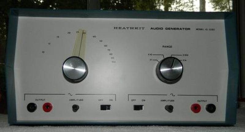
2 IG-5282 Audio Generator ig-5282 spec.txt The Heathkit IG-5282 Audio Generator is an audio frequency signal generator. It provides sine wave and square wave signals that may be used as a signal source for harmonic distortion measurements, as an external modulator for an RF signal generator, or in tests of audio amplifiers for gain or frequency response. The square wave signals can also be used to trigger digital instruments SPECIFICATIONS Frequency Output Hz to 100 khz in four ranges Sine Wave Output Voltage volts peak Square Wave Output Voltage volts peak Power Supply (2) 9-volt batteries or IPA Power Supply Dimensions /4 high, 11 wide, 7-3/4 deep Net Weight /2 lbs. Page 1
3 ig-5282 alignment instructions.txt Heathkit Information Page Heathkit Model IG-5282 Audio Generator Calibration Procedure If using the unit as a portable instrument, install a fresh set of 9-volt batteries and set the SOURCE switch (on rear of unit) to the BATT position. If powered using the IPA AC Power Supply, set the SOURCE switch (on rear of unit) to the LINE position. Disconnect all external components from the front panel terminals. Ancillary Equipment Needed Oscilloscope VTVM RESISTANCE CHECKS Refer to Pictorial 18 Illustration Booklet page 3 ( ) Temporarily remove the 9-volt batteries if installed. ( ) Set the SOURCE switch [on rear of unit] to the BATT position if connected to an IPA ( ) Set both POWER switches (sine and square waves) to the OFF positions. ( ) Set the VTVM FUNCTION switch to the OHMS position. ( ) Set the VTVM RANGE switch to the R x 100 position. ( ) Connect the VTVM common lead to the chassis. ( ) Touch the ohmmeter probe to the collector of transistor Q4. [Toward the front panel side of the SYM control on the circuit board] ( ) Meter indication should be 1000 W or higher when the pointer stops. ( ) Set the VTVM RANGE switch to the R x 10K position. ( ) Touch the ohmmeter probe to the collector of transistor Q5. [Left side of the BIAS ADJ control facing the tuning capacitor on the circuit board] ( ) Meter indication should be 100K W or higher. ( ) Set both POWER switches to the OFF positions. INITIAL CIRCUIT BOARD ADJUSTMENTS ( ) Install fresh batteries (if using them) and set the SOURCE switch to the BATT position. Page 1
4 ig-5282 alignment instructions.txt ( ) If the unit is powered using a IPA , set the SOURCE switch to the LINE position. ( ) Remove the upper ground shield (see Detail 20A). ( ) Set the FLATNESS ADJ control trimmer screw clockwise until snug. [Right side the tuning capacitor on the circuit board] ( ) Set the FLATNESS ADJ control trimmer screw one turn counter-clockwise. ( ) Set the sine wave AMPLITUDE control to maximum clockwise. ( ) Set the square wave AMPLITUDE control to maximum clockwise. ( ) Set the RANGE switch to the X 100 position. ( ) Set the DIAL FREQUENCY control to maximum counter-clockwise. INITIAL ADJUSTMENTS WITHOUT THE UPPER GROUND SHIELD Refer to Pictorial 10 Manual, page 20 ( ) Connect the common (ground) lead of the VTVM to the chassis. ( ) Set the VTVM FUNCTION switch to the DC+ position. ( ) Set the VTVM RANGE switch to the 15V position. ( ) Connect the VTVM probe to test point A. [White wire from bottom lug on terminal strip to connection B on the circuit board] ( ) Adjust the BIAS ADJ control for a zero volt meter indication. ( ) Set the RANGE switch to the X1 position. Adjust the FEEDBACK ADJ control at the lower frequency end of the band and the FLATNESS ADJ control at the higher frequency and of the band. No point across the band should exceed a 3 V indication. ( )* Set the DIAL FREQUENCY control to maximum counter-clockwise. ( )* Set the FEEDBACK ADJ control until a 3 V meter indication. [Behind the large tuning capacitor] ( )* Set the DIAL FREQUENCY control to maximum clockwise. ( )* Adjust the FLATNESS ADJ control trimmer screw until a 3 V meter indication. [Near right front of tuning capacitor on the circuit board] ( )* Adjust the DIAL FREQUENCY control through each frequency band. ( )* Note the highest meter indication and the frequency on each band. ( )* Set the DIAL FREQUENCY control to highest meter indication. ( )* Adjust the FEEDBACK ADJ control for a 3 V meter indication. Page 2
5 ig-5282 alignment instructions.txt ( ) Repeat the above eight steps* on all four frequency range bands. FINAL ADJUSTMENTS WITH THE UPPER GROUND SHIELD ( ) Set the RANGE switch to the X1k position. ( ) Set the DIAL FREQUENCY control to maximum clockwise. ( )* Set the upper ground shield in place and note the decrease in the meter indication. ( )* Remove the upper ground shield. ( )* Adjust the FLATNESS ADJ control trimmer for an increase in output voltage to compensate for the loss causes by the shield cover. ( )* Set the upper ground shield back in place and check for a 3 V meter indication. ( ) Repeat the above four steps* until a 3 V meter indication with the shield in place. ( ) Connect the meter probe to the positive (red) square wave output terminal. ( ) Set the VTVM FUNCTION input to the DC+ position. SQUARE WAVE SYMETRY ADJUSTMENT Adjustment without an oscilloscope option ( ) Adjust the SYM control for the largest meter indication. ( ) Adjust the SYM control for half the highest meter indication. ( ) Disconnect the VTVM leads from the generator. Adjustment with an oscilloscope option ( ) Connect an oscilloscope to the square wave output terminals. ( ) Set the vertical gain to 1 volt per centimeter. ( ) Set the sweep rate for a screen display of five cycles (see schematic trace D). ( ) Adjust the SYM control for the largest vertical trace. ( ) Adjust the vertical gain to keep the trace on the screen. ( ) Adjust the SYM control for a 50% duty cycle. ( ) Disconnect the oscilloscope from the generator. FINAL ADJUSTMENTS ( ) Install the upper ground shield. Page 3
6 ig-5282 alignment instructions.txt ( ) Set the sine wave AMPLITUDE control to maximum counter-clockwise. ( ) Set the square wave AMPLITUDE control to maximum counter-clockwise. ( ) Set the RANGE switch to the X1 position. ( ) Set the DIAL FREQUENCY control to maximum counter-clockwise. ( ) Set both POWER switches (sine and square waves) to the OFF positions. ( ) Calibration procedure is complete. Page 4
7
8
E-200D ALIGNMENT. See the end of the procedure for the location of the calibration points. EQUIPMENT REQUIRED
 E-200D ALIGNMENT NOTE: This is not an official B&K alignment procedure. This procedure was created by experimenting with an E-200D. However when this procedure is followed, the resulting calibration should
FMR622S DUAL NARROW BAND SLIDING DE-EMPHASIS DEMODULATOR INSTRUCTION BOOK IB
 FMR622S DUAL NARROW BAND SLIDING DE-EMPHASIS DEMODULATOR INSTRUCTION BOOK IB 1222-22 TABLE OF CONTENTS SECTION 1.0 INTRODUCTION 2.0 INSTALLATION & OPERATING INSTRUCTIONS 3.0 SPECIFICATIONS 4.0 FUNCTIONAL
Model 4402B. Ultra-Pure Sinewave Oscillator 1Hz to 110kHz Typical Distortion of % Serial No. Operating Manual
 Model 4402B Ultra-Pure Sinewave Oscillator 1Hz to 110kHz Typical Distortion of 0.0005% Serial No. Operating Manual 15 Jonathan Drive, Unit 4, Brockton, MA 02301 U.S.A. Tel: (508) 580-1660; Fax: (508) 583-8989
Laboratory 3 (drawn from lab text by Alciatore)
") Laboratory 3 (drawn from lab text by Alciatore) The Oscilloscope Required Components: 1 10 resistor 2 100 resistors 2 lk resistors 1 2k resistor 2 4.7M resistors 1 0.F capacitor 1 0.1 F capacitor 1 1.0uF
Laboratory 3 (drawn from lab text by Alciatore) The Oscilloscope Required Components: 1 10 resistor 2 100 resistors 2 lk resistors 1 2k resistor 2 4.7M resistors 1 0.F capacitor 1 0.1 F capacitor 1 1.0uF
The University of Jordan Mechatronics Engineering Department Electronics Lab.( ) Experiment 1: Lab Equipment Familiarization
 Experiment 1: Lab Equipment Familiarization") The University of Jordan Mechatronics Engineering Department Electronics Lab.(0908322) Experiment 1: Lab Equipment Familiarization Objectives To be familiar with the main blocks of the oscilloscope and
The University of Jordan Mechatronics Engineering Department Electronics Lab.(0908322) Experiment 1: Lab Equipment Familiarization Objectives To be familiar with the main blocks of the oscilloscope and
WESTREX RA-1712 PHOTOGRAPHIC SOUND RECORD ELECTRONICS
 INTRODUCTION The RA-1712 solid state Record Electronics is an integrated system for recording photographic sound tracks on a Westrex photographic sound recorder. It accepts a 600Ω input signal level from
EXPERIMENT 1 PRELIMINARY MATERIAL
 EXPERIMENT 1 PRELIMINARY MATERIAL BREADBOARD A solderless breadboard, like the basic model in Figure 1, consists of a series of square holes, and those columns of holes are connected to each other via
A Simple Notch Type Harmonic Distortion Analyzer
 by Kenneth A. Kuhn Nov. 28, 2009, rev. Nov. 29, 2009 Introduction This note describes a simple notch type harmonic distortion analyzer that can be constructed with basic parts. It is intended for use in
Exercise 1: AC Waveform Generator Familiarization
 Exercise 1: AC Waveform Generator Familiarization EXERCISE OBJECTIVE When you have completed this exercise, you will be able to operate an ac waveform generator by using equipment provided. You will verify
THE 1956 ZENITH ROYAL 500 TRANSISTOR OWL S EYES RADIO.
 THE 1956 ZENITH ROYAL 500 TRANSISTOR OWL S EYES RADIO. Dr. H. Holden. Feb. 2018. Introduction: The Zenith Royal 500 radio appeared in 1956, two years later than the Regency TR1 which was the first commercial
Instruction Manual. SSQ-2F Controller Board. For the. v1.41 For Rife Plasma Tube Systems. Manual v by Ralph Hartwell Spectrotek Services
 Instruction Manual For the SSQ-2F Controller Board v1.41 For Rife Plasma Tube Systems Manual v1.00 2012 by Ralph Hartwell Spectrotek Services This page intentionally blank. 2 Index and Table of Contents
RITEK RIT for Collins KWM-2/2A 10/01/2002
 RITEK RIT for Collins KWM-2/2A 10/01/2002 The RITEK RIT (receiver incremental tuning) control was developed for KWM-2/2A in 1992 to "clarify" received signals differing from the transmit frequency indicated
Using Circuits, Signals and Instruments
 Using Circuits, Signals and Instruments To be ignorant of one s ignorance is the malady of the ignorant. A. B. Alcott (1799-1888) Some knowledge of electrical and electronic technology is essential for
Building a Bitx20 Version 3
 Building a Bitx20 Version 3 The board can be broken into sections and then built and tested one section at a time. This will make troubleshooting easier as any problems will be confined to one small section.
MASTR II AUXILIARY RECEIVER 19D417546G7 & G8 & ANTENNA MATCHING UNITS 19C321150G1-G2. Maintenance Manual LBI-30766L. Mobile Communications
 L Mobile Communications MASTR II AUXILIARY RECEIVER 19D417546G7 & G8 & ANTENNA MATCHING UNITS 19C321150G1-G2 Printed in U.S.A Maintenance Manual TABLE OF CONTENTS Page SPECIFICATIONS.....................................................
FREQUENCY AGILE FM MODULATOR INSTRUCTION BOOK IB
 FMT615C FREQUENCY AGILE FM MODULATOR INSTRUCTION BOOK IB1215-02 TABLE OF CONTENTS SECTION SUBJECT 1.0 Introduction 2.0 Installation & Operating Instructions 3.0 Specification 4.0 Functional Description
Instrument Usage in Circuits Lab
 Instrument Usage in Circuits Lab This document contains descriptions of the various components and instruments that will be used in Circuit Analysis laboratory. Descriptions currently exist for the following
May 23, Diode Leakage In The SB-100, SB-101, HW-100
 May 23, 1974 Diode Leakage In The, SB-101, HW-100-1 The silicon diodes used in the SB100 & SB101 are standard power diodes rated at 500PIV & 750MA. For each condition described, the diodes should be replaced
Operation Manual. Model SG Elenco Precision Wide Band Signal Generator
 99 Washington Street Melrose, MA 02176 Phone 781-665-1400 Toll Free 1-800-517-8431 Visit us at www.testequipmentdepot.com Elenco Precision Wide Band Signal Generator Model SG-9000 Operation Manual CONTENTS
MFJ-752C SIGNAL ENHANCER II
 MFJ-752C SIGNAL ENHANCER II INTRODUCTION The improved MFJ-752C SIGNAL ENHANCER II is comprised of two tunable audio filtering systems designed to clarity and remove interfering signals from both voice
LBI-30398N. MAINTENANCE MANUAL MHz PHASE LOCK LOOP EXCITER 19D423249G1 & G2 DESCRIPTION TABLE OF CONTENTS. Page. DESCRIPTION...
 MAINTENANCE MANUAL 138-174 MHz PHASE LOCK LOOP EXCITER 19D423249G1 & G2 LBI-30398N TABLE OF CONTENTS DESCRIPTION...Front Cover CIRCUIT ANALYSIS... 1 MODIFICATION INSTRUCTIONS... 4 PARTS LIST AND PRODUCTION
Model Operating Manual
 Model 7500 DC to 1MHz Wideband Power Amplifier Operating Manual Copyright 2004. All rights reserved. Contents of this publication may not be reproduced in any form without the written permission of Krohn-Hite
ERICSSONZ LBI-30398P. MAINTENANCE MANUAL MHz PHASE LOCKED LOOP EXCITER 19D423249G1 & G2 DESCRIPTION TABLE OF CONTENTS
 MAINTENANCE MANUAL 138-174 MHz PHASE LOCKED LOOP EXCITER 19D423249G1 & G2 TABLE OF CONTENTS Page DESCRIPTION... Front Cover CIRCUIT ANALYSIS...1 MODIFICATION INSTRUCTIONS...4 PARTS LIST...5 PRODUCTION
DIGIT & POINTER MULTIMETER
 CONTENTS DIGIT & POINTER MULTIMETER OPERATOR S MANUAL 1. SAFETY INFORMATION 1 1.1 PRELIMINARY 1 1.2 DURING USE 2 1.3 SYMBOLS 3 1.4 MAINTENANCE 3 2. DESCRIPTION 4 2.1 NAMES OF COMPONENTS 4 2.2 FUNCTION
Exam Booklet. Pulse Circuits
 Exam Booklet Pulse Circuits Pulse Circuits STUDY ASSIGNMENT This booklet contains two examinations for the six lessons entitled Pulse Circuits. The material is intended to provide the last training sought
PHYSICS 171 UNIVERSITY PHYSICS LAB II. Experiment 4. Alternating Current Measurement
 PHYSICS 171 UNIVERSITY PHYSICS LAB II Experiment 4 Alternating Current Measurement Equipment: Supplies: Oscilloscope, Function Generator. Filament Transformer. A sine wave A.C. signal has three basic properties:
Keysight Measuring High Impedance Sources Using the U8903B Audio Analyzer. Application Note
 Keysight Measuring High Impedance Sources Using the U8903B Audio Analyzer Application Note Introduction This note details the input impedance of the U8903B Audio Analyzer, and shows that this needs to
EXPERIMENT 10: Power Amplifiers
 EXPERIMENT 10: Power Amplifiers 10.1 Examination Of Class A Amplifier 10.2 Examination Of Class B Amplifier 10.3 Examination Of Class C Amplifier BASIC ELECTRONICS set 15.1 INTRODUCTION There are classes
University of Jordan School of Engineering Electrical Engineering Department. EE 204 Electrical Engineering Lab
 University of Jordan School of Engineering Electrical Engineering Department EE 204 Electrical Engineering Lab EXPERIMENT 1 MEASUREMENT DEVICES Prepared by: Prof. Mohammed Hawa EXPERIMENT 1 MEASUREMENT
The Aleph 5 is a stereo 60 watt audio power amplifier which operates in single-ended class A mode.
 Pass Laboratories Aleph 5 Service Manual Rev 0 9/20/96 Aleph 5 Service Manual. The Aleph 5 is a stereo 60 watt audio power amplifier which operates in single-ended class A mode. The Aleph 5 has only two
Lab 1: Basic Lab Equipment and Measurements
 Abstract: Lab 1: Basic Lab Equipment and Measurements This lab exercise introduces the basic measurement instruments that will be used throughout the course. These instruments include multimeters, oscilloscopes,
When you have completed this exercise, you will be able to determine the frequency response of an
 RC Coupling When you have completed this exercise, you will be able to determine the frequency response of an oscilloscope. The way in which the gain varies with frequency is called the frequency response.
Exercise 2: FM Detection With a PLL
 Phase-Locked Loop Analog Communications Exercise 2: FM Detection With a PLL EXERCISE OBJECTIVE When you have completed this exercise, you will be able to explain how the phase detector s input frequencies
May 20, Transistor Socket Problem
 HD-10 May 20, 1971 Transistor Socket Problem HD-10-1F A vender change on this four-pin socket makes it unusable. All units in stock are being corrected - - but a run of HD-10 units has been shipped with
TMP-100 Turbine Meter Pulse Divider Circuit
 NUFLO TM TMP-100 Turbine Meter Pulse Divider Circuit User Manual Manual No. 9A-100080245, Rev. 01 2008 Cameron International Corporation ( Cameron). All information contained in this publication is confidential
ECE 480: SENIOR DESIGN LABORATORY
 ECE 480: SENIOR DESIGN LABORATORY DEPARTMENT OF ELECTRICAL AND COMPUTER ENGINEERING MICHIGAN STATE UNIVERSITY I. TITLE: Lab I - Introduction to the Oscilloscope, Function Generator, Digital Multimeter
Boonton 202E set to 200 mc, frequency modulated by HP 200 CD AUDIO oscillator, feeding a 10 u-v signal to the HI band receiver
 SRR-5 System Test Procedure w X J»"«". Tgra^^i nnnrww ini in m 1.0 HEADSET AUDIO Receiver Control Settings; Band: HI, set to 200 mc Function: FM Boonton 202E set to 200 mc, frequency modulated by HP 200
Chino Scientific Instruments Manufacturing
 DIGITAL MICRO OHM METER Chino s made DIGITAL MICRO OHM METER is a compact high reliability 3 ½ digit instrument suitable for measurement of resistivity of copper wires from 70 SWG to 50 SWG resistance
Experiment No. 9 DESIGN AND CHARACTERISTICS OF COMMON BASE AND COMMON COLLECTOR AMPLIFIERS
 Experiment No. 9 DESIGN AND CHARACTERISTICS OF COMMON BASE AND COMMON COLLECTOR AMPLIFIERS 1. Objective: The objective of this experiment is to explore the basic applications of the bipolar junction transistor
THE HONG KONG POLYTECHNIC UNIVERSITY EN107/1 Department of Electronic and Information Engineering. EN107: OCL Class AB Power Amplifier Objective
 THE HONG KONG POLYTECHNIC UNIVERSITY EN107/1 EN107: OCL Class AB Power Amplifier Objective 1. To study the circuit performance of an OCL amplifier. 2. To study the effects of biasing on cross-over distortion
APPENDIX D DISCUSSION OF ELECTRONIC INSTRUMENTS
 APPENDIX D DISCUSSION OF ELECTRONIC INSTRUMENTS DC POWER SUPPLIES We will discuss these instruments one at a time, starting with the DC power supply. The simplest DC power supplies are batteries which
HOM rev. new Heathkit of the Month #78: by Bob Eckweiler, AF6C. Heath of the Month #78 - IM-17 Utility Solid-State Voltmeter ELECTRONIC TEST EQUIPMENT
 Heathkit of the Month #78: by Bob Eckweiler, AF6C ELECTRONIC TEST EQUIPMENT HEATHKIT IM-17 Utility Solid-State Voltmeter Introduction: Over its history Heathkit sold many voltmeters. Probably most famous
MC2301. Features and Benefits. Promotional Highlights TUBE POWER AMPLIFIER MCINTOSH LABORATORY INC., 2 CHAMBERS STREET, BINGHAMTON, NEW YORK 13903
 MC2301 Product Preview Page 1 McIntosh Laboratory, Inc., Binghamton, NY 13903 Design Engineering Department PRODUCT PREVIEW MC2301 TUBE POWER AMPLIFIER Project 1336 Promotional Highlights 300 Watts Mono
UNITED MOTORS SERVICE D IV ISIO N OF GENERAL M O TO RS C O R P O R A T IO N. General Offices - Detroit AUTO RADIO BULLETIN
 UNITED MOTORS SERVICE D IV ISIO N OF GENERAL M O TO RS C O R P O R A T IO N General Offices - Detroit AUTO RADIO BULLETIN Bulletin 6D-855 Date 11-1-54 Page 1 FIRST ISSUE SUBJECT: SERVICE INSTRUCTIONS -
VCA. Voltage Controlled Amplifier.
 VCA Voltage Controlled Amplifier www.tiptopaudio.com Tiptop Audio VCA User Manual The Tiptop Audio VCA is a single-channel variable-slope voltage-controlled amplifier in Eurorack format. It has the following
FMR611S SUBCARRIER DEMODULATOR
 ALL ENGINEERING DESIGNS, DRAWINGS AND DATA CONTAINED HEREIN ARE PROPRIETARY AND MAY NOT BE REPRODUCED, COPIED OR OTHERWISE USED WITHOUT WRITTEN AUTHORIZATION FMR611S SUBCARRIER DEMODULATOR INSTRUCTION
Figure 2 shows the actual schematic for the power supply and one channel.
 Pass Laboratories Aleph 3 Service Manual rev 0 2/1/96 Aleph 3 Service Manual. The Aleph 3 is a stereo 30 watt per channel audio power amplifier which operates in single-ended class A mode. The Aleph 3
DISCRETE DIFFERENTIAL AMPLIFIER
 DISCRETE DIFFERENTIAL AMPLIFIER This differential amplifier was specially designed for use in my VK-1 audio oscillator and VK-2 distortion meter where the requirements of ultra-low distortion and ultra-low
Instructions MODIFICATION KIT MODEL SBM - 1O2-1 INTRODUCTION PARTS LIST FOR THE
 Instructions FOR THE MODIFICATION KIT MODEL SBM - 1O2-1 INTRODUCTION This modification Kit applies to the following Heath Transceivers: 1. All Models HW-100, SB-100, SB-101 and SB-101W. 2. Any Model SB-102
Heathkit of the Month #64 - VC-3 Voltage Calibrator
 Heathkit of the Month: by Bob Eckweiler, AF6C Heathkit VC-3 Voltage Calibrator. Introduction: The August 2013 Heathkit of the Month (#51) covered the IG-4505 Deluxe Oscilloscope Calibrator. It also briefly
The Aleph 2 is a monoblock 100 watt audio power amplifier which operates in single-ended class A mode.
 Pass Laboratories Aleph 2 Service Manual Rev 0 2/1/96 Aleph 2 Service Manual. The Aleph 2 is a monoblock 100 watt audio power amplifier which operates in single-ended class A mode. The Aleph 2 has only
DEPARTMENT OF THE ARMY TECHNICAL BULLETIN
 *TB 9-6625-1356-24 DEPARTMENT OF THE ARMY TECHNICAL BULLETIN CALIBRATION PROCEDURE FOR TEST OSCILLATOR, HEWLETT-PACKARD MODELS 651A, 651B AND 652A (SG-763/U) Headquarters Department of the Army, Washington,
MASSACHUSETTS INSTITUTE OF TECHNOLOGY
 Name: MASSACHUSETTS INSTITUTE OF TECHNOLOGY 6.091 Hands-On Introduction to EE Lab Skills Laboratory No. 1 Oscilloscopes, Multimeter, Function Generator IAP 2008 1 Objective In this laboratory, you will
Model Quality in Test and Measurement Since 1949 OUTSTANDING PERFORMANCE DESCRIPTION APPLICATIONS ADDITIONAL FEATURES
 Quality in Test and Measurement Since 1949 DC Source/Calibrators, Tunable Electronic Filters, Wideband Power Amplifiers Precision Phasemeters, Distortion Analyzers Function Generators, RC Oscillators Model
DIGITAL / ANALOG TRAINER
 DIGITAL / ANALOG TRAINER MODEL XK-150 A COMPLETE MINI-LAB FOR BUILDING, TESTING AND PROTOTYPING ANALOG AND DIGITAL CIRCUITS Instruction Manual ELENCO Copyright 2016, 1998 by ELENCO Electronics, Inc. All
Why Modern Servicing Requires Complete Waveform & Circuit Analyzing!
 Why Modern Servicing Requires Complete Waveform & Circuit Analyzing! DC Bias Voltages DC Currents Resistance AC Signals Of Various Waveshapes & Amplitudes Continuity Of Circuit Paths & Components If you
CON NEX HP. OWNER'S MANUAL Full Channel AM/FM Amateur Mobile Transceiver TABLE OF CONTENTS TUNING THE ANTENNA FOR OPTIMUM S.W.R..
 TABLE OF CONTENTS PAGE SPECIFICATIONS... 2 INSTALLATION... 3 LOCATION... 3 CON NEX - 4300HP MOUNTING THE RADIO... 3 IGNITION NOISE INTERFERENCE... 4 ANTENNA... 4 TUNING THE ANTENNA FOR OPTIMUM S.W.R..
 file:///c /BoatAnchors/Hammarlund/HQ170A/HQ170SVC.TXT Dear OM: This form is being prepared to provide prompt attention to a complaint as a result of trouble that may be experienced in the field. In addition
AC LAB ECE-D ecestudy.wordpress.com
 PART B EXPERIMENT NO: 1 AIM: PULSE AMPLITUDE MODULATION (PAM) & DEMODULATION DATE: To study Pulse Amplitude modulation and demodulation process with relevant waveforms. APPARATUS: 1. Pulse amplitude modulation
OBJECTIVES EQUIPMENT LIST
 1 Reception of Amplitude Modulated Signals AM Demodulation OBJECTIVES The purpose of this experiment is to show how the amplitude-modulated signals are demodulated to obtain the original signal. Also,
MFJ-208 VHF SWR Analyzer
 MFJ-208 VHF SWR Analyzer Thank you for purchasing the MFJ-208 VHF SWR Analyzer. The MFJ-208 gives you a direct readout of your antenna's SWR without the need for formulas or indirect readings. The MFJ-
D ELCO. electronic parts AUTO RADIO BULLETIN. Connect Signal Generator to
 D ELCO electronic parts AUTO RADIO BULLETIN Bulletin 6D-864 Date 10-15-56 Page 1 FIRST ISSUE SUBJECT: SERVICE INSTRUCTIONS - CHEVROLET CUSTOM DELUXE WITH PUSH BUTTON TUNING - MODEL 987575 GENERAL M O U
Receiver Adjustments
 ! -8-4!5 This Section details procedures for tuning and adjustment of T2000 series II radios. This is normally only required during product manufacture or after major servicing. The following topics are
ENGR 1110: Introduction to Engineering Lab 7 Pulse Width Modulation (PWM)
") ENGR 1110: Introduction to Engineering Lab 7 Pulse Width Modulation (PWM) Supplies Needed Motor control board, Transmitter (with good batteries), Receiver Equipment Used Oscilloscope, Function Generator,
ENGR 1110: Introduction to Engineering Lab 7 Pulse Width Modulation (PWM) Supplies Needed Motor control board, Transmitter (with good batteries), Receiver Equipment Used Oscilloscope, Function Generator,
Chapter 1: DC circuit basics
 Chapter 1: DC circuit basics Overview Electrical circuit design depends first and foremost on understanding the basic quantities used for describing electricity: Voltage, current, and power. In the simplest
EECS 318 Electronics Lab Laboratory #2 Electronic Test Equipment
 EECS 318 Electronics Lab Laboratory #2 Electronic Test Equipment Objectives: The purpose of this laboratory is to acquaint you with the electronic sources and measuring equipment you will be using throughout
TECHNICAL MANUAL ULTRASONIC TEST SET MODEL 42A12D JUNE 15, 1998 REV 00 SEACOM DIVISION
 TECHNICAL MANUAL ULTRASONIC TEST SET MODEL AD JUNE, 998 REV 00 SEACOM DIVISION DUKANE CORPORATION ST. CHARLES, ILLINOIS 607 PHONE: 60/8-00 FAX: 60/8- DOCUMENT NO. 0-TM-008 998 DUKANE CORPORATION 99806-08SC
When you have completed this exercise, you will be able to determine ac operating characteristics of a
 When you have completed this exercise, you will be able to determine ac operating characteristics of a multimeter and an oscilloscope. A sine wave generator connected between the transistor base and ground
ACCESSORY CIRCUITS ALIGNMENT
 UNIDEN 22 ACCESSOY CICUITS ALIGNMENT 1. NOISE BLANKE Adjustment 11. Test Equipment equired (1) DC Voltage Meter 12. Adjustment Procedures. (1) Set MODE SWITCH to USB, and recive 14.2 Mhz. (2) Activate
Copyright 2014, R. Eckweiler & OCARC, Inc. Page 1 of 6
 HOM rev. new Heathkit of the Month: by Bob Eckweiler, AF6C Heathkit of the Month #59 - IG-72 Audio Generator TEST EQUIPMENT Heathkit IG-72 Audio Generator. Introduction: The IG-72 Audio Oscillator is a
AME140 Lab #2 INTRODUCTION TO ELECTRONIC TEST EQUIPMENT AND BASIC ELECTRONICS MEASUREMENTS
 INTRODUCTION TO ELECTRONIC TEST EQUIPMENT AND BASIC ELECTRONICS MEASUREMENTS The purpose of this document is to guide students through a few simple activities to increase familiarity with basic electronics
LAB I. INTRODUCTION TO LAB EQUIPMENT
 1. OBJECTIVE LAB I. INTRODUCTION TO LAB EQUIPMENT In this lab you will learn how to properly operate the oscilloscope Agilent MSO6032A, the Keithley Source Measure Unit (SMU) 2430, the function generator
An Electronic Variable Load by Dave Chute, KG4BZW
 EDITOR: GEOFF HAINES, N1GY Published Quarterly N1GY@ARRL.NET Summer Edition FROM THE EDITOR: Once again I am happy to report that we have several great articles in the Summer Edition of The WCF Experimenter.
ASSEMBLY MANUAL FOR R3500D DIRECTION FINDING RECEIVER KIT
 SDR-Kits www.sdr-kits.net SDR-Kits is CRKITS Authorised Distributor for Europe ASSEMBLY MANUAL FOR R3500D DIRECTION FINDING RECEIVER KIT Rev. A May 24, 2015 Written by CRKITS http://www.crkits.com Thanks
MODEL FS-4 INSTRUCTION MANUAL R.L. DRAKE COMPANY, MIAMISBURG, OHIO, U.S.A.
 MODEL FS-4 F R E Q U E N C Y S Y N T H E S I Z E R INSTRUCTION MANUAL R.L. DRAKE COMPANY, MIAMISBURG, OHIO, U.S.A. LIMITED WARRANTY R. L. DRAKE COMPANY warrants to the original purchaser that this product
The Walford Electronics Ford Receiver Kit Project Construction Manual
 The Walford Electronics Ford Receiver Kit Project Construction Manual Walford Electronics Ford Receiver construction manual V1.5 Page 1 of 22 Introduction The Ford receiver has four stages: The first stage
VE7CNF - 630m Antenna Matching Measurements Using an Oscilloscope
 VE7CNF - 630m Antenna Matching Measurements Using an Oscilloscope Toby Haynes October, 2016 1 Contents VE7CNF - 630m Antenna Matching Measurements Using an Oscilloscope... 1 Introduction... 1 References...
Definitions. Spectrum Analyzer
 SIGNAL ANALYZERS Spectrum Analyzer Definitions A spectrum analyzer measures the magnitude of an input signal versus frequency within the full frequency range of the instrument. The primary use is to measure
KACHINA 1 SSB TRANSCEIVER
 KACHINA 1 SSB TRANSCEIVER THEORY OF OPERATION The Kachina 1 Amateur Band Transceiver is a highly sophisticated, state of the art, piece of communication equipment, housed in the smallest of packages. Yet,
Lab Equipment EECS 311 Fall 2009
 Lab Equipment EECS 311 Fall 2009 Contents Lab Equipment Overview pg. 1 Lab Components.. pg. 4 Probe Compensation... pg. 8 Finite Instrumentation Impedance. pg.10 Simulation Tools..... pg. 10 1 - Laboratory
EE431 Lab 1 Operational Amplifiers
 Feb. 10, 2015 Report all measured data and show all calculations Introduction The purpose of this laboratory exercise is for the student to gain experience with measuring and observing the effects of common
TM TECHNICAL MANUAL
 TECHNICAL MANUAL OPERATOR'S, ORGANIZATIONAL, DIRECT SUPPORT, AND GENERAL SUPPORT MAINTENANCE MANUAL VARIABLE FILTER, KROHN-HITE MODELS 3200(R) AND 3202(R) HEADQUARTERS, DEPARTMENT OF THE ARMY JULY 1972
Model 7000 Low Noise Differential Preamplifier
 Model 7000 Low Noise Differential Preamplifier Operating Manual Service and Warranty Krohn-Hite Instruments are designed and manufactured in accordance with sound engineering practices and should give
A 3-STAGE 5W AUDIO AMPLIFIER
 ECE 2201 PRELAB 7x BJT APPLICATIONS A 3-STAGE 5W AUDIO AMPLIFIER UTILIZING NEGATIVE FEEDBACK INTRODUCTION Figure P7-1 shows a simplified schematic of a 3-stage audio amplifier utilizing three BJT amplifier
Experiment 8 Frequency Response
 Experiment 8 Frequency Response W.T. Yeung, R.A. Cortina, and R.T. Howe UC Berkeley EE 105 Spring 2005 1.0 Objective This lab will introduce the student to frequency response of circuits. The student will
ENGR 210 Lab 6 Use of the Function Generator & Oscilloscope
 ENGR 210 Lab 6 Use of the Function Generator & Oscilloscope In this laboratory you will learn to use two additional instruments in the laboratory, namely the function/arbitrary waveform generator, which
Quadra 10 Available in Black and White
 S P E C I F I C A T I O N S Quadra 10 Available in Black and White Frequency response, 1 meter on-axis, swept-sine in anechoic environment: 74 Hz 18 khz (±3 db) Usable low frequency limit (-10 db point):
OPERATING AND MAINTENANCE MANUAL
 5Hz to 1MHz WIDE RANGE FULLY AUTOMATIC DISTORTION ANALYZER MODEL 6900B SERIAL NO. OPERATING AND MAINTENANCE MANUAL Unit 4, 15 Jonathan Drive, Brockton, MA 02301-5566 Tel: (508) 580-1660; Fax: (508) 583-8989
University of TN Chattanooga Physics1040L 8/29/2012 PHYSICS 1040L LAB LAB 6: USE OF THE OSCILLOSCOPE
 PHYSICS 1040L LAB LAB 6: USE OF THE OSCILLOSCOPE Object: To become familiar with the operation of the oscilloscope and be able to use an oscilloscope for: 1. Measuring the frequency of an oscillator, 2.
FIELD INTENSITY METER MODEL FIM-41 OPERATING INSTRUCTIONS
 FIELD INTENSITY METER MODEL FIM-41 OPERATING INSTRUCTIONS POTOMAC INSTRUMENTS, INC. 932 Philadelphia Ave. Silver Spring, MD 20910 Phone (301) 589-2662 Fax (301) 589-2665 www.pi-usa.com 2.1 General SECTION
Q106A Oscillator. Aug The Q106A Oscillator module is a combination of the Q106 Oscillator and the Q141 Aid module, all on a single panel.
 Aug 2017 The Q106A Oscillator module is a combination of the Q106 Oscillator and the Q141 Aid module, all on a single panel. The Q106A Oscillator is the foundation of any synthesizer providing the basic
CHAPTER 6. Motor Driver
 CHAPTER 6 Motor Driver In this lab, we will construct the circuitry that your robot uses to drive its motors. However, before testing the motor circuit we will begin by making sure that you are able to
How to make audio measurements on stereo receivers and amplifiers
 How to make audio measurements on stereo receivers and amplifiers HOW TO INCREASE YOUR SALES Many dealers are using performance tests on the sales floor to sell customers up to a more expensive item. Such
SoftRock v6.0 Builder s Notes. May 22, 2006
 SoftRock v6.0 Builder s Notes May 22, 2006 Be sure to use a grounded tip soldering iron in building the v6.0 SoftRock circuit board. The soldering iron needs to have a small tip, (0.05-0.1 inch diameter),
Ph 3455 The Franck-Hertz Experiment
 Ph 3455 The Franck-Hertz Experiment Required background reading Tipler, Llewellyn, section 4-5 Prelab Questions 1. In this experiment, we will be using neon rather than mercury as described in the textbook.
MFJ SIGNAL ENHANCER II
 MFJ SIGNAL ENHANCER II Model MFJ-752D INSTRUCTION MANUAL CAUTION: Read All Instruction Before Operating Equipment MFJ ENTERPRISES, INC. P.O. BOX 494, MISSISSIPPI STATE, MS 39762, USA 925-0037D-752D-REV
User Guide. Ring Modulator - Dual Sub Bass - Mixer
 sm User Guide Ring Modulator - Dual Sub Bass - Mixer Thank you for purchasing the AJH Synth Ring SM module, which like all AJH Synth Modules, has been designed and handbuilt in the UK from the very highest
EXAMPLE. Use this jack for the red test lead when measuring. current from 0 to 200mA. Figure P-1
 Digital Multimeters ON / OFF power switch Continuity / Diode Test Function Resistance Function Ranges from 200Ω to 200MΩ Transistor Test Function DC Current Function Ranges from 2mA to 20A. AC Current
CHANGE 1 DEPARTMENT OF THE ARMY TECHNICAL BULLETIN CALIBRATION PROCEDURE FOR RADIO TEST SET, AN/GRM-114A (IFR, MODEL FM/AM-1100S)
") CHANGE 1 DEPARTMENT OF THE ARMY TECHNICAL BULLETIN CALIBRATION PROCEDURE FOR RADIO TEST SET, AN/GRM-114A (IFR, MODEL FM/AM-1100S) Headquarters, Department of the Army, Washington, DC 24 September 2004
CHANGE 1 DEPARTMENT OF THE ARMY TECHNICAL BULLETIN CALIBRATION PROCEDURE FOR RADIO TEST SET, AN/GRM-114A (IFR, MODEL FM/AM-1100S) Headquarters, Department of the Army, Washington, DC 24 September 2004
Group: Names: (1) In this step you will examine the effects of AC coupling of an oscilloscope.
 In this step you will examine the effects of AC coupling of an oscilloscope.") 3.5 Laboratory Procedure / Summary Sheet Group: Names: (1) In this step you will examine the effects of AC coupling of an oscilloscope. Set the function generator to produce a 5 V pp 1kHz sinusoidal output.
3.5 Laboratory Procedure / Summary Sheet Group: Names: (1) In this step you will examine the effects of AC coupling of an oscilloscope. Set the function generator to produce a 5 V pp 1kHz sinusoidal output.