Reconstructing my Hallicrafters SX-28A. John Staples, W6BM
|
|
|
- Christopher White
- 5 years ago
- Views:
Transcription

1 February 2017 Reconstructing my Hallicrafters SX-28A John Staples, W6BM I say reconstructing instead of recapping because in my youthful ignorance, I took a perfectly good receiver, stripped it and rebuilt it to my fantasy. History I was gifted this receiver at the young age of ten by a friend of the family, hoping that it might lead me to get interested in radio. This gift could be the reason I am what I am today. Here is a youthful K9CPZ at my first station in 1956 comprising the SX-28A, a Heath AT-1 with a homebrew modulator, VFO and electronic keyer. Over the following years, in my exuberance, I continued to modify the receiver with all the latest gadgetry to improve its performance. Lately I recognized the error of my ways, and returned the receiver back to approximately its original configuration. The Modifications, or the horrors I inflicted on this receiver About the only area remaining relatively unmodified was the power supply and audio section. The entire RF/IF chain was replaced, a product detector included, along with a crystal calibrator and audio notch filter. The revised front-end included a hot 6EH7 frame-grid pentode and a 6X8 pentode mixer including a triode buffer stage isolating it from the 6C4 local oscillator. The six metal octal front-end and first two IF stages were replaced with 7 and 9-pin miniatures. The Lamb noise blanker was removed to make room for other circuits. The original and modified tube lineups give a good indication of what happened: Stage Original Modified First RF 6AB7 6EH7 Frame grid semi-remote cutoff pentode Second RF 6SK7 6BA6 Remote cutoff pentode Mixer 6SA7 6X8 Triode buffer, pentode mixer Oscillator 6SA7 6C4 Triode First AVC Amp 6B8 - Dual AVC system not used First IF 6L7 6BC5 Lamb noise circuit eliminated Second IF 6SK7 6AU6


2 Third IF - 6AC7 Added IF, detector driver Detector ½ 6B8 1N38A S-meter Amplifier ½ 6B8 6SJ7 BFO 6J5 - Product Detector - 6SA7 Includes BFO Noise Amplifier 6AB7 - Lamb noise circuit eliminated Noise Detector 6H6 - Lamb noise circuit eliminated Noise Limiter - 2 x 1N34 Simple series diode clipper First Audio 6SC7 6SC7 No change Audio Output 2 x 6V6 2 x 6V6 No change Voltage Regulator - VR-150 Added voltage regulation Rectifier 5Z3 5Z3 No change Crystal Calibrator - TTL ICs Audio Notch Filter - Analog Op amps The radio worked quite well! But it was no longer an SX-28A. Rebuild My preference now is to remove modifications, restore equipment to their original configuration and enjoy them as contemporary artifacts of their time. For the SX-28A, this meant stripping it down to bare chassis and rebuilding it from the ground up according to the original schematic. Fortunately, the IF transformers that had been removed decades ago were still in my possession, so the receiver could be approximately recreated as original, the largest difference being the wiring itself. Here is the receiver with all its added modifications. Note the six miniature tubes in the RF/IF section, new IF transformers in the upper right, near a voltage regulator (and some dirt).


3 The first task was to strip the receiver and remove and replace the incorrect tube sockets, all the RF modules and the incorrect IF transformers. The receiver was then built back up, starting with the power supply and audio stages. The electrolytic capacitors are replaced by units with high peak current rating on a newly-installed terminal strip to hold them. The audio stages are to the left with the 6SC7 first amplifier and phase splitter and the two 6V6 push-pull output amplifiers behind the output transformer. The next stages to be rebuilt start with the detector and work backwards in the IF amplifier chain up to the first IF stage. This way, each stage can be tested by injecting a suitable signal at each point and measuring the gain of each stage before the next stage is replaced.


4 Each IF transformer is uncased and capacitors replaced. New leads replace the original wire leads in all of the IF transformers. The second IF amplifier is the 6SK7 at the left behind the bandspread flywheel. Following it, to the right, are the 6B8 detector and the 6J5 BFO tube. These are connected to the 6SC7 first audio stage, seen at the right behind the main tuning flywheel. A 455 khz signal is injected into the grid of the 6SK7 to make sure that following stages are working correctly and have the correct gain. After these stages have been wired and checked, installation begins on the rest of the first IF amplifier and the rather complex Lamb noise blanker. The crystal filter and bandwidth switch are at the right.


5 The Lamb circuit detects large noise pulses, rectifies them, and then applies them to a grid of the 6L7 first IF amplifier, cutting the amplifier off. This circuit works very well on impulse noise and suppresses it before it is amplified by the narrow-selectivity IF chain, which broadens impulse noise. This circuit uses several tubes, and is not found in many receivers due to its added expense. These days, impulse noise from automobile ignition systems is largely gone, so the Lamb limiter is of less value in noise reduction. The rest of the IF strip and the Lamb noise limiter is shown here. Off to the right is the mode switch for the AVC and BFO. The original switch was lost, so a 2-wafer switch was configured to support the same functions. Note the tube suspended in air above the IF strip. This tube, a 6SK7 pentode, temporarily takes the place of the 6SA7 mixer, not yet installed, and loads and drives the primary of the first IF transformer with the correct driving impedance so that the IF gain can be measured and the primary of the transformer can be correctly tuned. The SX-28A uses an unusual dual AVC system. One system senses the signal strength right after the mixer, before the narrow-band IF and controls the gain of the RF amplifiers. This system starts to function significantly off frequency before any strong stations are within the narrow bandwidth of the IF strip. A second independent AVC system detects the signal strength at the end of the IF strip and controls the gain of the IF amplifier. This system helps to control RF overload and cross-modulation in the RF amplifiers by reducing the RF gain for strong off-frequency signals.


6 Finally, the modified RF modules are returned to their original configuration with octal tubes.


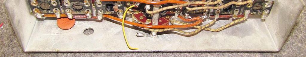
7 The miniature tube sockets are removed and the original octal sockets reinstalled. The original wafer switch at the front of the oscillator module has been lost. It controlled the IF gain separately for each band, as well as the RF AVC action for each band. New switch sections were found and configured to support these functions. The capacitors in each of the RF modules were replaced. The receiver is shown here without front panel with all controls temporarily hooked up, along with the S-meter for an initial checkout The audio volume and RF gain controls hang off to the left, the ANL control at the bottom, and the BFO variable capacitor at to near the 6V6 output tubes. The AVC/BFO switch hangs off at the lower left. After final assembly, the bottom of the receiver shows the RF/Mixer/Oscillator coil assembly. With smaller passive components and wire with thinner insulation, the receiver appears much roomier underneath than the original.


8 Looking down from the top, the receiver now looks more like the original, with the original IF transformers back in place. Some of the thinner wiring is evident. With the RF shield cover removed, the original metal octal tubes occupy the RF section, oscillator at the top, first RF stage at the bottom.

9 What parts came out of the receiver after the un-modification? Six miniature tubes and their hardware, many passive components, a pegboard with several components from the modified IF/audio sections, an op-amp audio notch filter, and an IC-based crystal calibrator giving 100 and 500 khz markers. The SX-28A now sits proudly next to my unmodified restored SX-28 (both out of their cases). Both receivers work very well and are fully competitive with other premium receivers of their vintage.
Copyright 2016, R. Eckweiler & OCARC, Inc. Page 1 of 8
 HOM rev. new Heathkit of the Month: by Bob Eckweiler, AF6C Heathkit of the Month #72 - HW-12/22/32 SSB Transceivers Pt. II AMATEUR RADIO - SWL Heathkit HW-12 / HW-22 / HW-32 Single-Bander SSB Transceivers
KWM-2/2A Transceiver THE COLLINS KWM-2/2A TRANSCEIVER
 KWM-2/2A Transceiver Click the photo to see a larger photo Click "Back" button on browser to return Courtesy of Norm - WA3KEY THE COLLINS KWM-2/2A TRANSCEIVER Unmatched for versatility, dependability and
Society of Wireless Pioneers - California Historical Radio Society
 Society of Wireless Pioneers - California Historical Radio Society RESISTOR VALUES ARE IN OHMS AND 1/2 WfcTT UNLESS OTHERWISE SPECIFIED CAPACITOR VALUES ARE IN MMF UNLESS OTHERWISE SPECIFIED. BANO SELECTOR
Copyright 2012, R. Eckweiler & OCARC, Inc. Page 1 of 8
 HOM rev. new Heathkit of the Month #36: by Bob Eckweiler, AF6C Heathkit of the Month #36 - SB-301 HF Ham Band Receiver Heathkit SB-301 HF Ham Band Receiver Introduction: Shortly after graduating from college
 file:///c /BoatAnchors/Hammarlund/HQ170A/HQ170SVC.TXT Dear OM: This form is being prepared to provide prompt attention to a complaint as a result of trouble that may be experienced in the field. In addition
Treetop Circuits Owner s Manual for SB-SB-600 Adapter Version 1
 The SB-600 SSB adapter from Treetop Circuits (Fig. 1) is designed specifically as an accessory to the Hammarlund SP-600 series of receivers. It provides enhanced performance on SSB and CW signals, using
HALLICRAFTERS SERVICE HINT NO. 21 October 20, Production Run Identification (Refer Service Policy Letter #9, dated Nov.
 HALLICRAFTERS SERVICE HINT NO. 21 October 20, 1947 SUBJECT: DISCUSSION: Model SX-42 Receiver Production Run Identification (Refer Service Policy Letter #9, dated Nov. 14, 1946) * * * * * * * * * * * *
The New England Radio Discussion Society electronics course (Phase 4, cont d) Introduction to receivers
 Introduction to receivers") The New England Radio Discussion Society electronics course (Phase 4, cont d) Introduction to receivers AI2Q April 2017 REVIEW: a VFO, phase-locked loop (PLL), or direct digital synthesizer (DDS), can
The New England Radio Discussion Society electronics course (Phase 4, cont d) Introduction to receivers AI2Q April 2017 REVIEW: a VFO, phase-locked loop (PLL), or direct digital synthesizer (DDS), can
UNITED MOTORS SERVICE AUTO RADIO BULLETIN
 UNITED MOTORS SERVICE DIVISION OF GENERAL MOTORS CORPORATION General Offices - Detroit AUTO RADIO BULLETIN Bulletin 6D-854 Date 11-1-54 Page 1 FIRST ISSUE GENERAL SUBJECT: SERVICE INSTRUCTIONS - 12V CHEVROLET
51J-4 COMMUNICATIONS RECEIVER
 51J-4 COMMUNICATIONS RECEIVER Transcribed from 520-5014-00 August 15, 1954 GENERAL DESCRIPTION The Collins 51J-4 Receiver is designed for communication applications where stability and dial accuracy of
Instructions MODIFICATION KIT MODEL SBM - 1O2-1 INTRODUCTION PARTS LIST FOR THE
 Instructions FOR THE MODIFICATION KIT MODEL SBM - 1O2-1 INTRODUCTION This modification Kit applies to the following Heath Transceivers: 1. All Models HW-100, SB-100, SB-101 and SB-101W. 2. Any Model SB-102
You Just Brought an Old Radio Home: Now What Do You Do?
 You Just Brought an Old Radio Home: Now What Do You Do? Raymond Cady goldenageradiorestoration.com Whether you are just beginning to collect antique radios or you have been at it for a number of years,
National HRO Receivers. Presented to the Ozaukee Radio Club May 10, 2017 Patrick Volkmann W9JI
 National HRO Receivers Presented to the Ozaukee Radio Club May 10, 2017 Patrick Volkmann W9JI Why the HRO? In the 1930 s a superhetrodyne receiver was considered almost useless for shortwave work. James
HF Receivers, Part 2
 HF Receivers, Part 2 Superhet building blocks: AM, SSB/CW, FM receivers Adam Farson VA7OJ View an excellent tutorial on receivers NSARC HF Operators HF Receivers 2 1 The RF Amplifier (Preamp)! Typical
1.0 General Description
 1.0 General Description Figure 1 - Plug-N-Play Noise Blanker for the Collins 75S-1 Series The Collins Noise Blanker is designed to be a Plug-N-Play accessory for the Collins 75S-1 series. The Noise Blanker
The Electro-Magnetic Spectrum
 The Electro-Magnetic Spectrum Part Three In This Issue: All about Tubes How a diode rectifier works How a triode amplifier works How the mixer in your receiver works Dear Friends: For quite some time I
Hallicrafters SX-88 Owners Manual
 Hallicrafters SX-88 Owners Manual Images and text excerpted from original Hallicrafters literature. Section 1. General Description The Hallicrafters SX-88 represents the ultimate in precision communications
UNITED MOTORS SERVICE D IV ISIO N OF GENERAL M O TO RS C O R P O R A T IO N. General Offices - Detroit AUTO RADIO BULLETIN
 UNITED MOTORS SERVICE D IV ISIO N OF GENERAL M O TO RS C O R P O R A T IO N General Offices - Detroit AUTO RADIO BULLETIN Bulletin 6D-855 Date 11-1-54 Page 1 FIRST ISSUE SUBJECT: SERVICE INSTRUCTIONS -
HOM rev. new Heathkit of the Month #77: by Bob Eckweiler, AF6C. Heath of the Month #77 - Hi Fi Broadcast Tuner AUDIO HI-FI EQUIPMENT
 Heathkit of the Month #77: by Bob Eckweiler, AF6C AUDIO HI-FI EQUIPMENT Heathkit BC-1A BROADCAST TUNER Introduction: In 1956 Heathkit had about a half-dozen Hi-Fi amplifiers in their stable. Many could
TS-930: Installing the Inrad Roofing Filter Mod
 TS-930: Installing the Inrad Roofing Filter Mod The TS-930 roofing filter mod consists of a 6 pole, 4 to 5 khz wide filter followed by a high dynamic range, feedback amplifier. The amplifier provides enough
CW-ADD. Universal CW Adapter for SSB Transceivers. Assembly manual. Last updated: October 1,
 CW-ADD Universal CW Adapter for SSB Transceivers Assembly manual Last updated: October 1, 2017 ea3gcy@gmail.com Updates and news at: www.ea3gcy.com Thanks for building the Universal CW Adapter kit CW-ADD
AS Electronics Project: 3-Channel Sound-to-Light Display
 : 3-Channel Sound-to-Light Display By 1. Contents 1. CONTENTS...2 2. AIM...3 3. SPECIFICATION...3 4. POSSIBLE SOLUTIONS...4 4.1. FILTERS...4 4.2. RECTIFIERS...4 5. CHOSEN SOLUTION...5 5.1. BUFFER...5 5.2.
12kHz LIF Converter V2.43 9Mhz version
 12kHz LIF Converter V2.43 9Mhz version Please Note: This document supersedes all previously released documents and drawings on the LIF subject. This is the latest and most up-to-date document at this time.
SECTION NEUTRALIZATION BELOW VHF NEUTRALIZATION
 SECTION 5 NEUTRALIZATION A completely neutralized amplifier must fulfill two conditions. The first is that the interelectrode capacitance between the input and output circuits be cancelled. The second
1.0 General Description
 1.0 General Description Figure 1 Plug-N-Play Noise Blanker for the Collins KWM-2/2A The Collins Noise Blanker is designed to be a Plug-N-Play accessory for the Collins KWM-2/2A transceivers. It plugs directly
Approximate Circuit Model for a Magnetic Pickup Piezoelectric Pickups Piezoelectric Pickup Analysis Guitar Volume and Tone Control
 Contents 1 Power Supplies... 1 Introduction... 1 A Simple Power Supply Circuit..... 1 The Transformer.............. 2 The Rectifier........................................................ 3 The Frequency
Maintenance Manual TRANSMITTER/RECEIVER BOARD CMN-233 FOR MLSH041
 Maintenance Manual TRANSMITTER/RECEIVER BOARD CMN-233 FOR MLSH041 TABLE OF CONTENTS Page DESCRIPTION... 2 CIRCUIT ANALYSIS... 2 Transmitter... 2 9-volt Regulator... 2 Exciter... 2 40-Watt PA... 2 Antenna
S-Pixie QRP Kit. Student Manual. Revision V 1-0
 S-Pixie QRP Kit Student Manual Revision V 1-0 Introduction The Pixie 2 is a small, versatile radio transceiver that is very popular with QRP (low power) amateur radio operators the world over. It reflects
MAINTENANCE MANUAL TRANSMITTER/RECEIVER BOARD CMN-234A/B FOR MLSU141 & MLSU241 UHF MOBILE RADIO TABLE OF CONTENTS
 MAINTENANCE MANUAL TRANSMITTER/RECEIVER BOARD CMN-234A/B FOR MLSU141 & MLSU241 UHF MOBILE RADIO TABLE OF CONTENTS DESCRIPTION... 2 CIRCUIT ANALYSIS... 2 TRANSMITTER... 2 9-Voft Regulator... 2 Exciter...
The G4EGQ RAE COURSE Lesson 9 Transmitters Lesson 8 looked at a simple transmitter exciter comprising of oscillator, buffer and multiplier stages.
 Lesson 8 looked at a simple transmitter exciter comprising of oscillator, buffer and multiplier stages. The power amplifier The output from the exciter is usually very low and it is necessary to amplify
Automatic Tracking Filter for DDS Generator
 Riccardo Gionetti, IØFDH Via S. Bernadette, 00 Roma RM, Italy: rgionetti@virgilio.it Automatic Tracking Filter for DDS Generator Reduce spurious responses from a digital synthesizer with this filter. The
The KW 76A MOBILE RECEIVER
 The KW 76A MOBILE RECEIVER The KW 76A Receiver is designed primarily for mobile operation. The compact layout makes it particularly suitable for under dash mounting in a vehicle. When used at a Home station
LBI-30398N. MAINTENANCE MANUAL MHz PHASE LOCK LOOP EXCITER 19D423249G1 & G2 DESCRIPTION TABLE OF CONTENTS. Page. DESCRIPTION...
 MAINTENANCE MANUAL 138-174 MHz PHASE LOCK LOOP EXCITER 19D423249G1 & G2 LBI-30398N TABLE OF CONTENTS DESCRIPTION...Front Cover CIRCUIT ANALYSIS... 1 MODIFICATION INSTRUCTIONS... 4 PARTS LIST AND PRODUCTION
HF Amateur SSB Receiver
 HF Amateur SSB Receiver PCB Set for radio club project http://rhelectronics.net PCB for DIY HF Amateur SSB Receiver 20M The receiver is a simple syperheterodyne type with quartz crystal filter. The circuit
N3ZI Kits General Coverage Receiver, Assembly & Operations Manual (For Jun 2011 PCB ) Version 3.33, Jan 2012
 Version 3.33, Jan 2012") N3ZI Kits General Coverage Receiver, Assembly & Operations Manual (For Jun 2011 PCB ) Version 3.33, Jan 2012 Thank you for purchasing my general coverage receiver kit. You can use the photo above as a
N3ZI Kits General Coverage Receiver, Assembly & Operations Manual (For Jun 2011 PCB ) Version 3.33, Jan 2012 Thank you for purchasing my general coverage receiver kit. You can use the photo above as a
IC-781: Installing the Inrad Roofing Filter Mod
 IC-781: Installing the Inrad Roofing Filter Mod The Icom IC-781 roofing filter mod consists of a 6-pole, 4 to 5 khz wide filter followed by a high dynamic range, feedback amplifier. The amplifier provides
TS-850: Installing the Inrad Roofing Filter Mod
 TS-850: Installing the Inrad Roofing Filter Mod The TS-850 Roofing Filter Mod consists of a 6 pole, 4 to 5 khz wide filter followed by a high dynamic range feedback amplifier. The amplifier provides enough
Knight Kit V44 VFO Stabilized by the Cumbria Design X-Lock 3.0
 Knight Kit V44 VFO Stabilized by the Cumbria Design X-Lock 3.0 The Knight V44 VFO has a place in history. It was designed in the late 1950 s as a self contained VFO intended to plug into the crystal socket
Technician License Course Chapter 3 Types of Radios and Radio Circuits. Module 7
 Technician License Course Chapter 3 Types of Radios and Radio Circuits Module 7 Radio Block Diagrams Radio Circuits can be shown as functional blocks connected together. Knowing the description of common
HOMEBREW Q-MULTIPLIER
 HOMEBREW Q-MULTIPLIER This circuit can boost the signal strength in your receiver by 1 or 2 S-units, giving approximately 10 db gain. A Q-multiplier amplifies the Q of the first IF transformer so that
ERICSSONZ LBI-30398P. MAINTENANCE MANUAL MHz PHASE LOCKED LOOP EXCITER 19D423249G1 & G2 DESCRIPTION TABLE OF CONTENTS
 MAINTENANCE MANUAL 138-174 MHz PHASE LOCKED LOOP EXCITER 19D423249G1 & G2 TABLE OF CONTENTS Page DESCRIPTION... Front Cover CIRCUIT ANALYSIS...1 MODIFICATION INSTRUCTIONS...4 PARTS LIST...5 PRODUCTION
IPR LA-3 KIT last update 15 march 06
 IPR LA-3 KIT last update 15 march 06 PART-2: Audio Circuitry CIRCUIT BOARD LAYOUT: Power and Ground Distribution Now that your power supply is functional, it s time to think about how that power will be
FREQUENCY AGILE FM MODULATOR INSTRUCTION BOOK IB
 FMT615C FREQUENCY AGILE FM MODULATOR INSTRUCTION BOOK IB1215-02 TABLE OF CONTENTS SECTION SUBJECT 1.0 Introduction 2.0 Installation & Operating Instructions 3.0 Specification 4.0 Functional Description
Overview of the MSA 12/30/10
 Overview of the MSA 12/30/10 Introduction The purpose of this document is to provide an overview of the capabilities and construction of the MSA to help potential builders get oriented. Much more detailed
Building a Bitx20 Version 3
 Building a Bitx20 Version 3 The board can be broken into sections and then built and tested one section at a time. This will make troubleshooting easier as any problems will be confined to one small section.
KACHINA 1 SSB TRANSCEIVER
 KACHINA 1 SSB TRANSCEIVER THEORY OF OPERATION The Kachina 1 Amateur Band Transceiver is a highly sophisticated, state of the art, piece of communication equipment, housed in the smallest of packages. Yet,
THE 1956 ZENITH ROYAL 500 TRANSISTOR OWL S EYES RADIO.
 THE 1956 ZENITH ROYAL 500 TRANSISTOR OWL S EYES RADIO. Dr. H. Holden. Feb. 2018. Introduction: The Zenith Royal 500 radio appeared in 1956, two years later than the Regency TR1 which was the first commercial
UNITED MOTORS SERVICE D IV ISIO N OF GENERAL M O TO RS C O R P O R A T IO N. General Offices - Detroit AUTO RADIO BULLETIN
 UNITED MOTORS SERVICE D IV ISIO N OF GENERAL M O TO RS C O R P O R A T IO N General Offices - Detroit AUTO RADIO BULLETIN Page 1 FIRST ISSUE SUBJECT: SERVICE INSTRUCTIONS - CHEVROLET TRUCK MODEL 987187
LINEAR IC APPLICATIONS
 1 B.Tech III Year I Semester (R09) Regular & Supplementary Examinations December/January 2013/14 1 (a) Why is R e in an emitter-coupled differential amplifier replaced by a constant current source? (b)
UNIT-3. Electronic Measurements & Instrumentation
 UNIT-3 1. Draw the Block Schematic of AF Wave analyzer and explain its principle and Working? ANS: The wave analyzer consists of a very narrow pass-band filter section which can Be tuned to a particular
ALM473 DUAL MONO \ STEREO AUDIO LEVEL MASTER OPERATION MANUAL IB
 ALM473 DUAL MONO \ STEREO AUDIO LEVEL MASTER OPERATION MANUAL IB6408-01 TABLE OF CONTENTS GENERAL DESCRIPTION 2 INSTALLATION 2,3,4 CONNECTION AND SETUP 4,5,6,7 FUNCTIONAL DESCRIPTION 8,9 MAINTENANCE 9
Super Stealth Monobloc Power Amplifier
 Super Stealth Monobloc Power Amplifier Special Edition Users' Manual Rev. Oct. /1 Mapletree Audio Design Lloyd Peppard R. R. 1, Seeley's Bay, Ontario, Canada, K0H N0 (61) -0 info@mapletreeaudio.com http://www.mapletreeaudio.com
AD8232 EVALUATION BOARD DOCUMENTATION
 One Technology Way P.O. Box 9106 Norwood, MA 02062-9106 Tel: 781.329.4700 Fax: 781.461.3113 www.analog.com AD8232 EVALUATION BOARD DOCUMENTATION FEATURES Ready to use Heart Rate Monitor (HRM) Front end
NEW. HANDMADE in Germany.
 NEW HANDMADE in Germany. Integrated amplifier Ti 100 Mk II The Lyric Ti 100 Mk II is a pure single-ended class A amplifier. Its subtlety, naturalness, charm and dynamics converge for a fantastic listening
HOM rev. new. Heath of the Month #80 - K-1 All-Wave Receiver. Heathkit of the Month #80: by Bob Eckweiler, AF6C AMATEUR RADIO - SWL
 Heathkit of the Month #80: by Bob Eckweiler, AF6C AMATEUR RADIO - SWL The Heathkit K-1 Three-Tube All-Wave Beginner s Receiver Some K-1 All-Wave Receiver History: The first piece of radio equipment using
Maintenance Manual ERICSSONZ LBI-31552E
 E Maintenance Manual TONE REMOTE CONTROL BOARD 19A704686P4 (1-Frequency Transmit Receive with Channel Guard) 19A704686P6 (4-Frequency Transmit Receive with Channel Guard) ERICSSONZ Ericsson Inc. Private
Sweep / Function Generator User Guide
 I. Overview Sweep / Function Generator User Guide The Sweep/Function Generator as developed by L. J. Haskell was designed and built as a multi-functional test device to help radio hobbyists align antique
Copyright 2016, R. Eckweiler & OCARC, Inc. Page 1 of 7
 Heathkit of the Month: by Bob Eckweiler, AF6C ELECTRONIC TEST EQUIPMENT Heathkit IM-38 AC Vacuum Tube Voltmeter (VTVM). Introduction: Back in March of 2013 Heathkit of the Month #47 discussed the Heathkit
SPECIFICATIONS: Subcarrier Frequency 5.5MHz adjustable, FM Modulated +/- 50KHz. 2nd 11MHz >40dB down from 5.5MHz
 Mini-kits AUDIO / SUBCARRIER KIT EME75 Version4 SPECIFICATIONS: Subcarrier Frequency 5.5MHz adjustable, FM Modulated +/- 50KHz Subcarrier Output 1.5v p-p Output @ 5.5MHz DESCRIPTION & FEATURES: The Notes
A 75-Watt Transmitter for 3 Bands Simplified Shielding and Filtering for TVI BY DONALD H. MIX, W1TS ARRL Handbook 1953 and QST, October 1951
 A 75-Watt Transmitter for 3 Bands Simplified Shielding and Filtering for TVI BY DONALD H. MIX, W1TS ARRL Handbook 1953 and QST, October 1951 The transmitter shown in the photographs is a 3-stage 75-watt
RF System: Baseband Application Note
 Jimmy Hua 997227433 EEC 134A/B RF System: Baseband Application Note Baseband Design and Implementation: The purpose of this app note is to detail the design of the baseband circuit and its PCB implementation
CX7 Troubleshooting Index
 CX7 Troubleshooting Index Modification S/1 Newsletter Guide Board Description A/TO A/TO MODE Intermod V1,12 P4.4 A11 Shut off one 35 MHz osc in receive, done sn 244 A/TO Spur V1,12 P1 Reduce A/TO spur,
Part I - Amplitude Modulation
 EE/CME 392 Laboratory 1-1 Part I - Amplitude Modulation Safety: In this lab, voltages are less than 15 volts and this is not normally dangerous to humans. However, you should assemble or modify a circuit
CompuLign User Guide - V2.0
 CompuLign User Guide - V2.0 I. Overview The CompuLign computer driven alignment tool as developed by L. J. Haskell was designed and built as a multi-functional test device to help radio hobbyists align
Radio Receivers. Al Penney VO1NO
 Radio Receivers Role of the Receiver The Antenna must capture the radio wave. The desired frequency must be selected from all the EM waves captured by the antenna. The selected signal is usually very weak
GRID CONTROLLED POWER SUPPLY IS A VERSATILE UNIT Uses Pair of RCA-2050 s for Wide Voltage Range
 10/30/07 11:55 PM Thyratrons GRID CONTROLLED POWER SUPPLY IS A VERSATILE UNIT Uses Pair of RCA-2050 s for Wide Voltage Range By J. H. OWENS, W2FTW and G. D. HANCHETT, W1AK/2 RCA Ham Tips Volume 6, Number
Radio Receivers. Al Penney VO1NO
 Radio Receivers Al Penney VO1NO Role of the Receiver The Antenna must capture the radio wave. The desired frequency must be selected from all the EM waves captured by the antenna. The selected signal is
TS-870: Installing the Inrad Roofing Filter Mod
 TS-870: Installing the Inrad Roofing Filter Mod The TS-870 roofing filter mod consists of a 6 pole, 4 to 5 khz wide filter followed by a high dynamic range feedback amplifier. The amplifier provides enough
ericssonz LBI-38640E MAINTENANCE MANUAL FOR VHF TRANSMITTER SYNTHESIZER MODULE 19D902780G1 DESCRIPTION
 MAINTENANCE MANUAL FOR VHF TRANSMITTER SYNTHESIZER MODULE 19D902780G1 TABLE OF CONTENTS Page DESCRIPTION........................................... Front Cover GENERAL SPECIFICATIONS...................................
Transceiver selection and Specs.
 Transceiver selection and Specs. Transceivers 1956-2018 From TUBES to SDR Covers 20-10 meters in 100Khz segments, 10 available, crystal needed for each. Plug in crystal holder. 100 Watts output, final
Ten-Tec Orion Synthesizer - Design Summary. Abstract
 Ten-Tec Orion Synthesizer - Design Summary Lee Jones 7/21/04 Abstract Design details of the low phase noise, synthesized, 1 st local oscillator of the Ten-Tec model 565 Orion transceiver are presented.
IC-756 Pro III vs. Pro II
 IC-756 Pro III vs. Pro II Improvements in the Pro III vs. the Pro II Adam Farson VA7OJ IC-756Pro3 Information & Links Copyright 2006 North Shore Amateur Radio Club NSARC HF Operators 756Pro3 vs. Pro2 1
IC-765: Installing the Inrad Roofing Filter Mod
 IC-765: Installing the Inrad Roofing Filter Mod The Icom IC-765 roofing filter mod consists of a 6-pole, 4 khz wide filter followed by a high dynamic range, feedback amplifier. The amplifier provides enough
TDA7000 for narrowband FM reception
 TDA7 for narrowband FM reception Author: Author: W.V. Dooremolen INTRODUCTION Today s cordless telephone sets make use of duplex communication with carrier frequencies of about.7mhz and 49MHz. In the base
ssb transceiver single-band using the LM373 communications IC
 single-band ssb transceiver using the LM373 communications IC How to use the versatile LM373 and several other ICs to build a compact ssb transceiver for 14 MHz About two years ago a new products announcement
UNITED MOTORS SERVICE. DIVISION OF GENERAL MOTORS CORPORATION General Offices - Detroit AUTO RADIO BULLETIN
 UNITED MOTORS SERVICE DIVISION OF GENERAL MOTORS CORPORATION General Offices - Detroit AUTO RADIO BULLETIN Bulletin 6D-848 Chevrolet 986515 Page 1 SUBJECT: SERVICE INSTRUCTIONS CHEVROLET CUSTOM DELUXE
Definitions. Spectrum Analyzer
 SIGNAL ANALYZERS Spectrum Analyzer Definitions A spectrum analyzer measures the magnitude of an input signal versus frequency within the full frequency range of the instrument. The primary use is to measure
RF/IF Terminology and Specs
 RF/IF Terminology and Specs Contributors: Brad Brannon John Greichen Leo McHugh Eamon Nash Eberhard Brunner 1 Terminology LNA - Low-Noise Amplifier. A specialized amplifier to boost the very small received
A NEW GENERATION PROGRAMMABLE PHASE/AMPLITUDE MEASUREMENT RECEIVER
 GENERAL A NEW GENERATION PROGRAMMABLE PHASE/AMPLITUDE MEASUREMENT RECEIVER by Charles H. Currie Scientific-Atlanta, Inc. 3845 Pleasantdale Road Atlanta, Georgia 30340 A new generation programmable, phase-amplitude
RF Generators. Requirements:
 Requirements: RF Generators to deliver a requested forward power (adjustable) level into an RF system power level is adjusted manually, or power level is controlled by a digital or analog input signal
Receiver Specification?
 Receiver Specification? What do they mean? Steve Finch AIØW What We re Doing Today Stage-by-stage receiver gain what do they mean? Specifications of interest why? Test equipment needed Learn about the
Heathkit of the Month #64 - VC-3 Voltage Calibrator
 Heathkit of the Month: by Bob Eckweiler, AF6C Heathkit VC-3 Voltage Calibrator. Introduction: The August 2013 Heathkit of the Month (#51) covered the IG-4505 Deluxe Oscilloscope Calibrator. It also briefly
4/30/2012. General Class Element 3 Course Presentation. Practical Circuits. Practical Circuits. Subelement G7. 2 Exam Questions, 2 Groups
 General Class Element 3 Course Presentation ti ELEMENT 3 SUB ELEMENTS General Licensing Class Subelement G7 2 Exam Questions, 2 Groups G1 Commission s Rules G2 Operating Procedures G3 Radio Wave Propagation
Custom Integrated Circuit (MSM9520RS) Replacement Module
 Replacement Module") FT-101Z/ FT-107/ FT-707/ FT-901,902 (later version) DISPLAY COUNTER UNIT (PB-2086A) Custom Integrated Circuit (MSM9520RS) Replacement Module Assembly and Installation Manual (v1.3e) STEP-BY-STEP PROCEDURES
FT-101Z/ FT-107/ FT-707/ FT-901,902 (later version) DISPLAY COUNTER UNIT (PB-2086A) Custom Integrated Circuit (MSM9520RS) Replacement Module Assembly and Installation Manual (v1.3e) STEP-BY-STEP PROCEDURES
EKB Shortwave Receiver made in GDR by VEB Funktechnik Dabendorf
 All pictures hb9aik - vk2ani EKB Shortwave Receiver made in GDR by VEB Funktechnik Dabendorf Restauration of the Czech Model R5 with AC P.S. Description & Picture Gallery Page 1/10 Preface: The Small Print
A Frequency Doubler and Distribution Amplifier for the Lucent KS GPS Disciplined Reference Generator
 Gerhard W. Hoffmann: A Frequency Doubler and Distribution Amplifier for the Lucent KS-24361 GPS Disciplined Reference Generator ghf@hoffmann-hochfrequenz.de Hoffmann RF & DSP Potsdamer Allee 26 D66606
Operation Manual. SlJPER ST AR Channel Mobile 5-Mode Transceiver -----~- --:.. KTSS200NXX ,, I
 Operation Manual!.,, SlJPER ST AR 2000 200 Channel Mobile 5-Mode Transceiver -----~- --:.. KTSS200NXX General Description l Frequency/Channel Chart The Super Star -2000 is a combination transmitter-receiver
1. General Outline Project Proposal April 9, 2014 Kayla Esquivel and Jason Yang
 1. General Outline 6.101 Project Proposal April 9, 2014 Kayla Esquivel and Jason Yang The invention and mass application of radio broadcast was triggered in the first decade of the nineteenth century by
PRACTICE. Amateur Radio Operator Certificate Examination. Advanced Qualification
 Amateur Radio Operator ertificate Examination Advanced Qualification 2019-04-03 To pass this exam, you must correctly answer 35 out of 50 questions Exam Number: 115916 1. (A-007-008-002) Why would one
Updating the RME-4300/4350/4350A Receiver
 Updating the RME-4300/4350/4350A Receiver By Dale Parfitt, W4OP P O BOX 645 Glenville, NC 28736 par@parelectronics.com Introduction As a young ham (1962 WV2YPY) with very little money, I was always lusting
GRID DIP METER DESIGN
 GRID DIP METER DESIGN BY G0CWA MAY 2013 This, my next offering of test equipment is an exceptionally useful item of test equipment with many uses, some are listed below. To coin a phrase given to me by
An Electronic Watt-Watt-Hour Meter
 An Electronic Watt-Watt-Hour Meter The continued emphasis on energy conservation has forced designers to consider the power consumption and efficiency of their products. While equipment for the industrial
Dual Band Filter Assembly Manual
 Dual Band Filter Assembly Manual 12 January 2018 Rev D Version Theory of Operation: The purpose of a Bandpass Filter is to filter out or reject all unwanted signals. The original KN-Q7A Receive Filter
Introduction Introduction to radio frequencies p. 3 What are the 'radio frequencies'? p. 3 Why are radio frequencies different? p.
 Foreword p. xi Preface p. xiii Introduction Introduction to radio frequencies p. 3 What are the 'radio frequencies'? p. 3 Why are radio frequencies different? p. 3 What this book covers p. 3 Signals and
THE AMAZING BARLOW WADLEY XCR-30 CRYSTAL CONTROLLED 30 BAND TRANSISTOR RADIO. (A method to set the AGC) H. Holden, 2018.
 H. Holden, 2018.") THE AMAZING BARLOW WADLEY XCR-30 CRYSTAL CONTROLLED 30 BAND TRANSISTOR RADIO. (A method to set the AGC) H. Holden, 2018. Introduction: The Barlow Wadley XCR-30 radio is well known to amateur radio enthusiasts
THE AMAZING BARLOW WADLEY XCR-30 CRYSTAL CONTROLLED 30 BAND TRANSISTOR RADIO. (A method to set the AGC) H. Holden, 2018. Introduction: The Barlow Wadley XCR-30 radio is well known to amateur radio enthusiasts
The 6LE8 One Tube Broadcaster
 The 6LE8 One Tube Broadcaster Introduction The purpose of this broadcaster is to transmit your favorite music to every AM radio in your home. The transmitting power is so low that it should not bother
The VMARS Newsletter Issue 32 The Yaesu FT200 Colin Guy G4DDI
 The Yaesu FT200 Colin Guy G4DDI The Yaesu FT200 is an SSB/CW transceiver that covers the pre-warc amateur bands from 80m to 10m. An almost all valve design that provides around 180watts PEP, good stability
Treetop Circuits Owner s Manual for SB-390 SSB Adapter Version 3
 The SB-390 SSB adapter (Fig. 1) from Treetop Circuits is designed specifically as an accessory for the R-390 and R-390A receivers. It provides enhanced performance on SSB and CW signals, using a product
E L E C R A F T K N B 1 N O I S E B L A N K E R
 Introduction E L E C R A F T K N B N O I S E B L A N K E R Assembly and Operating Instructions Revision C, Jan. 8, 200. Copyright 200, Elecraft; All Rights Reserved The KNB noise blanker can be used to
Information on small CW receivers can be found in the ARRL handbook, QRP handbooks and the Internet.
 The FOXFINDER-8 WEB UPDATE (DRAFT v2. SUBJECT TO CHANGE) A lot of modifications have occurred since the introduction of the original article. This update incorporates them and also corrects some errors