Blue Ring Tester Kit Assembly & User Manual
|
|
|
- Nathan Joseph
- 5 years ago
- Views:
Transcription

1 Blue Ring Tester Kit Assembly & User Manual Alltronics LLC/AnaTek Instruments 2761 Scott Blvd, Santa Clara, CA, 95050, USA March 2015 Edition Tel: , Fax: , E mail : tech@alltronics.com This Ring Tester is an inexpensive and effective way to test any high-q inductive component. It is especially useful for doing a quick check on flyback, line output transformers and other high frequency wound components like deflection yoke windings and SMPS transformers. The LEDs on the left side show the Q of the device being tested, the more lights = the higher Q: No Lights = Short Circuit, Red = Bad or Low Q, Yellow = Marginal/Medium Q, Green = Good or High Q. This document was written and edited by John Bachman, Ken Maybury and Andy Franklin at AnaTek. Last updated 3/10/2015
2

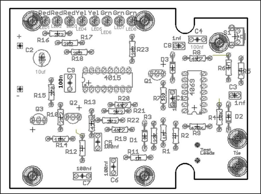
3 Parts List Resistors all 5% ¼ Watt Capacitors all 16 WV minimum 270 Ω, R15 Red-Blue-Brown 510 Ω, R7 Green-Brown-Brown 2.2 KΩ, R10, R16, R17, R18, R21, R22, R23 Red-Red-Red 4.7KΩ, R8, R19, R20 Yellow-Violet-Red 10 KΩ, R4, R14 Brown-Black-Orange 22 KΩ, R3 Red-Red-Orange 470 KΩ, R9, R13 Yellow-Violet-Yellow 1 MΩ, R1, R2, R5, R6, R11, R12 Brown-Black-Green Semiconductors 1 nf ceramic, C3, C8 1N4148, D1, D2, D3 100 nf ceramic, C1, C4, C5, C6 C7, C9 2N3904, Q1, Q2, Q3 10 uf electrolytic, C2 CD4069, IC1 CD4015, 1C2 Red LED, LED1, LED2, Yellow LED, LED4, LED5 Green LED, LED6, LED7, LED8 Miscellaneous Pushbutton switch with cap Blue Hammond enclosure Label Plastic shim Pair of test leads Pair of alligator clips with insulators 3 tie wrap 2 grommets printed circuit board ferrite core and wire
4 Construction As you can see in the photos, all the components are mounted on a single PC board which is then attached to the enclosure bottom. Even though the pc board is high-quality with solder-mask it is still wise to check it for defects. To do this, illuminate the component side with a bright light and examine the copper side very carefully preferably with a magnifier for any hairline fractures in the tracks. During assembly frequently check for any solder whiskers or bridges and pay particular attention to any tracks, which pass between IC pads, where such defects tend to congregate and hide. It is good practice to install 5 or 6 components and then check the soldering of them under a magnifier. Then move on and install 5 or 6 more. The PC board is tightly packed and the solder pads are quite small so be very careful with your soldering. Always lift the iron vertically from a just soldered joint and never wipe it sideways as so many constructors seem to do! Component Installation Sequence The kit package contains four plastic bags of components. Install them in the following order: 5% resistors Capacitors Semiconductors (See detailed description of LED installation) Miscellaneous parts The bag labeled Misc Parts contains an inductor that you will use after your unit is assembled. The inductor is not installed on the pc board. Installing components The construction sequence basically installs the smallest components first. The table of color codes above will help you select the resistor values prior to checking. Take care with the orientation of the polarized components: the electrolytic capacitor, diodes, LEDs and transistors. OPTION: Some kit builders are nervous about soldering directly to the integrated circuit pins and prefer to install sockets for that reason. Feel free to do so although sockets are not included in the kit. If you solder your integrated circuits and manage to damage them in doing so contact AnaTek. We will replace the integrated circuits for FREE!

 LED8 into")


5 Resistors Installed Semiconductors (NOT LEDs) Installed LED shim use Capacitors Installed See picture above for use of the plastic shim for aligning the LEDs. Put red LED1 in place and green (it looks clear) LED8 into place and slide the shim under them. Then put the other LEDs into place and press all of them against the shim. Bend the leads to hold them into place and solder. Then slide the shim out. This makes the LEDs the same height. Adjust to line them up in a line. Short leads go to the outside of the PCB. See the note on the noncomponent side of the board indicating the short lead position.


6 Test lead installation Strip approximately 1/8 (2 mm) from one end of the test leads and tin using rosin core solder. Install the grommets into the enclosure end panel as shown in the picture. Then push the test leads through the grommets. The outside of the panel is the finished side. Yes, the leads fit tightly in the grommets, they are supposed to. Then solder the test leads to the pc board and secure them with the tie wrap. Leave enough slack for the leads to clear around the pc board holes for the enclosure bosses. Strip approximately ¼ (4 mm) from the other end of the test leads, do not tin them. Push alligator clip insulators onto the leads first and then push the lead end into the center hole of the alligator clips as shown in the picture. Then solder the lead to the clip, trimming it so that the insulator can be slid over the clip. Use rosin core solder to make the soldering easier. Finished PCB Assembly

7 Battery connector When all the components are on the board, solder the battery snap connector to the battery pads on the PC board - red to + and black to -. Final Assembly The pc board sits snugly in the bottom enclosure. Fasten the board into place using the five selftapping screws. Remove the battery compartment door from the bottom of the enclosure and feed the battery leads through the opening and as shown in the picture.

8 Initial checks Connect a 9 volt battery to the battery connector and press the button switch once. One or two of the red LEDs should be flickering, that is the power on signal. If the leads are wrapped around each other more LED s will flicker. Press the button again to turn it off. Test inductor Wrap the enameled wire supplied into the center holes of the ferrite core supplied in the bag labeled Test over and over tightly to form a test coil as shown in the picture. Strip the enamel insulation off the ends of the wires for good contact to the copper wire. Heating the enamel over an open flame will make it easier to strip by scraping. Connect the ring tester clips to the two wires of your test inductor. All LEDs should be on solidly. You are done! That s it! Install the enclosure top and secure it with the four self-tapping screws. Push the battery into its compartment and install the battery compartment door. Then put the label on the front and start testing inductive components! How does the Ring Tester work? The components in many circuits including display drivers, SMPS and tuning circuits contain low loss (high Q) resonant circuits. The testing technique used in this design is based on the fact that many faults in magnetic components result in increased loss = reduced Q. Ring testing gets its name from the fact that a when fast voltage pulse is applied to a high Q circuit the tuned nature of the circuit will produce a decaying AC voltage of several cycles. More cycles, or rings, means higher Q. Few or no cycles indicates a problem in that component, a shorted winding or some other malady. This tester provides a quick and easy way to track down such problems. Send any questions to tech@alltronics.com.
9 Consider this set of waveforms from a flyback transformer, aka, LOPT. Waveform A shows the ring response to this tester s pulse for a good FBT/LOPT. Note several rings in a decaying fashion. This tester will count the rings that exceed its threshold and display them as lit LEDs as shown in the simulation to the right of waveform A. Waveform B is the response from the same FBT/LOPT with a shorted diode. The tester will show only one or two red LEDs lit (solidly as opposed to the blinking power on indication) as show in the simulation to the right of waveform B. A short anywhere in the circuit, such as the HOT, will show no rings at all. Different FBTs will exhibit a different ring response. Some will light all of the LEDs as shown above and others, while perfectly good, will light only five or six LEDs. It is wise to check a known good component for comparison before deciding good/bad. High voltage failures that occur only with power on may not be detected by this low voltage ring tester. Because this unit uses pulses of 600 millivolts or less it will not detect those failures. However the low voltage permits many in-circuit tests so making a happy compromise. While much of our discussion is directed at FBT/LOPT devices the ring tester is not limited to them. It will give a rough but useful indication of good/no good for many types of Hi-Q (low loss) inductive components.
STEADY HAND GAME WITH LATCHING LED
 ESSENTIAL INFORMATION BUILD INSTRUCTIONS CHECKING YOUR PCB & FAULT-FINDING MECHANICAL DETAILS HOW THE KIT WORKS TEST YOUR HAND-EYE COORDINATION WITH THIS STEADY HAND GAME WITH LATCHING LED Version 2.0
DIODE / TRANSISTOR TESTER KIT
 DIODE / TRANSISTOR TESTER KIT MODEL DT-100K Assembly and Instruction Manual Elenco Electronics, Inc. Copyright 1988 Elenco Electronics, Inc. Revised 2002 REV-K 753110 DT-100 PARTS LIST If you are a student,
DIODE / TRANSISTOR TESTER KIT
 DIODE / TRANSISTOR TESTER KIT MODEL DT-100K 99 Washington Street Melrose, MA 02176 Phone 781-665-1400 Toll Free 1-800-517-8431 Visit us at www.testequipmentdepot.com Assembly and Instruction Manual Elenco
Build this Direct Digital Synthesizer "Development Kit" By: Diz Gentzow, W8DIZ
 Build this Direct Digital Synthesizer "Development Kit" By: Diz Gentzow, W8DIZ A great tutorial for adding a keypad to the DDS Kit by Bruce, W8BH This manual has been prepared to be read directly on screen.
SoftRock v6.0 Builder s Notes. May 22, 2006
 SoftRock v6.0 Builder s Notes May 22, 2006 Be sure to use a grounded tip soldering iron in building the v6.0 SoftRock circuit board. The soldering iron needs to have a small tip, (0.05-0.1 inch diameter),
12V Dimmer Kit, version 2
 12V Dimmer Kit, version 2 User Manual Description The 12V Dimmer Kit V2 is an especially efficient PWM (pulse-width modulation) controller for 12V loads up to 60 watts. It features a single dial control
WA3RNC 30 METER CRYSTALPLEXER TRANSMITTER KIT ASSEMBLY INSTRUCTIONS
 WA3RNC 30 METER CRYSTALPLEXER TRANSMITTER KIT ASSEMBLY INSTRUCTIONS Description The WA3RNC 30 Meter Crystalplexer is a low power crystal controlled QRP transmitter offering a significantly improved tuning
SPACE WAR GUN KIT MODEL K-10. Assembly and Instruction Manual. Elenco Electronics, Inc.
 SPACE WAR GUN KIT MODEL K-10 Assembly and Instruction Manual Elenco Electronics, Inc. Copyright 1989 Elenco Electronics, Inc. Revised 2001 REV-H 753210A PARTS LIST Contact Elenco Electronics (address/phone/e-mail
SoftRock v6.0 Builder s Notes. April 6, 2006
 SoftRock v6.0 Builder s Notes April 6, 006 Be sure to use a grounded tip soldering iron in building the v6.0 SoftRock circuit board. The soldering iron needs to have a small tip, (0.05-0. inch diameter),
LED ROBOT BLINKER KIT
 LED ROBOT BLINKER KIT MODEL K-17 Assembly and Instruction Manual Elenco Electronics, Inc. Copyright 1989, 1998 Elenco Electronics, Inc. Revised 2001 REV-J 753217 PARTS LIST If any parts are missing or
Easy Transmitter. Support ETX_REV5_Manual V2.7 Revised
 Easy Transmitter Introduction The Easy Transmitter kit from qrpkits.com provides a basic, crystal controlled transmitter with VXO tuning to provide a small tuning range around the crystal frequency. It
TELEPHONE BUG KIT MODEL K-35. Assembly and Instruction Manual
 TELEPHONE BUG KIT MODEL K-35 Assembly and Instruction Manual Elenco Electronics, Inc. Copyright 2010, 1989 by Elenco Electronics, Inc. All rights reserved. Revised 2010 REV-L 753235 No part of this book
Elektor Construction Guide TAPIR
 Elektor Construction Guide TAPIR The TAPIR is a three-dimensional assembly. To ensure good access to all soldering points, we recommend assembling the kit exactly according to the described sequence. 1
Pacific Antenna Easy TR Switch
 Pacific Antenna Easy TR Switch Kit Description The Easy TR Switch is an RF sensing circuit with a double pole double throw relay that can be used to automatically switch an antenna between a separate receiver
SoftRock v5.0 Builder s Notes. December 12, Building a QSD Kit
 SoftRock v5.0 Builder s Notes December 12, 2005 Building a QSD Kit Be sure to use a grounded tip soldering iron in building the QSD board. The soldering iron needs to have a small tip, (0.05-0.1 inch diameter),
Electronics Merit Badge Class 4. 12/30/2010 Electronics Merit Badge Class 4 1
 Electronics Merit Badge Class 4 12/30/2010 Electronics Merit Badge Class 4 1 Soldering Safety Note: A Soldering Iron gets hotter than 374 F. Do not touch the soldering iron s metal parts or you will receive
Assembly Instructions for the FRB FET FM 70 Watt Amp
 Assembly Instructions for the FRB FET FM 70 Watt Amp 1.) Orient the circuit board with the diagram 2.) Use a narrow chisel tip 25-30 watt soldering iron for assembly 3.) All the small parts are taped onto
Pacific Antenna Low Pass Filter Kit
 Pacific Antenna Low Pass Filter Kit Description Many basic transmitter and/or transceiver designs have minimal filtering on their output and frequently have significant harmonic content in their signals.
AM RADIO KIT MODEL AM-780K. Assembly and Instruction Manual
 AM RADIO KIT MODEL AM-780K Assembly and Instruction Manual Elenco Electronics, Inc. Copyright 2007, 1999 by Elenco Electronics, Inc. All rights reserved. Revised 2007 REV-F 753108 No part of this book
Pacific Antenna Wall Wart Tamer 2.0 Kit
 Pacific Antenna Wall Wart Tamer 2.0 Kit Description The Wall Wart Tamer lets you utilize those surplus computer and wall pack power supplies as a clean, adjustable voltage, DC power source for radios and
DuoDrive Nixie Bargraph Kit
 Assembly Instructions And User Guide Nixie Bargraph Kit - 1 - REVISION HISTORY Issue Date Reason for Issue Number 1 12 December 2017 New document - 2 - 1. INTRODUCTION 1.1 About Nixie Bargraph Driver IN-9
Gat ew ay T o S pace AS EN / AS TR Class # 07. Colorado S pace Grant Consortium
 Gat ew ay T o S pace AS EN / AS TR 2500 Class # 07 Colorado S pace Grant Consortium One Minute Reports: - Can we have two data loggers? - Do you provide us with cameras? {Hardware Checkout after proposal}
Pacific Antenna Easy Transmitter Kit
 Pacific Antenna Easy Transmitter Kit Introduction The Easy Transmitter kit from qrpkits.com provides a crystal controlled transmitter with VXO tuning. The circuit consists of a N3904 based crystal oscillator
HW-8-TR V3 PARTS LIST
 HW-8-TR V3 PARTS LIST Qty Ref Description Markings 4C2 C3 C4 C5 Capacitor Disc.1ls.1uF 104 1 C1 Capacitor Disc.2ls.1uF 100V 104 1 QSKMOD-C92 Capacitor Electrolytic 1uF 50V 1 QSKMOD Capacitor Mylar.47uF
Building the Sawdust Regenerative Receiver
 Building the Sawdust Regenerative Receiver Introduction The Sawdust is a super regenerative receiver using the basic Armstrong design architecture. The receiver uses one toroidal transformer to provide
IR add-on module circuit board assembly - Jeffrey La Favre January 27, 2015
 IR add-on module circuit board assembly - Jeffrey La Favre January 27, 2015 1 2 For the main circuits of the line following robot you soldered electronic components on a printed circuit board (PCB). The
V6.2 SoftRock Lite Builder s Notes. November 17, 2006
 V6.2 SoftRock Lite Builder s Notes November 17, 2006 Be sure to use a grounded tip soldering iron in building the v6.2 SoftRock circuit board. The soldering iron needs to have a small tip, (0.05-0.1 inch
LDB-1 Kit Instructions Page 1 of 8
 LDB-1 Kit Instructions Page 1 of 8 Important Information Congratulations and thank you for your purchase of the LDB-1 Little Drummer Boy Analog Drum Machine Kit! Before you start, please read the enclosed
Pacific Antenna - Easy TR Switch
 Pacific Antenna - Easy TR Switch Kit Description The Easy TR Switch is an RF sensing switch that can be used to switch an antenna between a receiver and transmitter. It also has a second switched pair
Executive Decision Maker Pro Assembly Guide
 Assembly Guide 1 Introduction Congratulations with acquiring your Executive Decision Make Pro. This guide attempts to follow you through the entire assembly process and should give you help to find order
MONO AMPLIFIER KIT ESSENTIAL INFORMATION. Version 3.0 CREATE YOUR OWN SPEAKER DOCK WITH THIS
 ESSENTIAL INFORMATION BUILD INSTRUCTIONS CHECKING YOUR PCB & FAULT-FINDING MECHANICAL DETAILS HOW THE KIT WORKS CREATE YOUR OWN SPEAKER DOCK WITH THIS MONO AMPLIFIER KIT Version 3.0 Build Instructions
FM RADIO KIT ESSENTIAL INFORMATION. Version 2.0 GET IN TUNE WITH THIS
 ESSENTIAL INFORMATION BUILD INSTRUCTIONS CHECKING YOUR PCB & FAULT-FINDING MECHANICAL DETAILS HOW THE KIT WORKS GET IN TUNE WITH THIS FM RADIO KIT Version 2.0 Build Instructions Before you start, take
YAP BOX KIT MODEL K-22A YAP BOX SIX EXCITING SOUNDS. Assembly and Instruction Manual
 YAP BOX KIT MODEL K-22A YAP BOX SIX EXCITING SOUNDS Assembly and Instruction Manual Elenco Electronics, Inc. Copyright 2009, 1989 by Elenco Electronics, Inc. All rights reserved. Revised 2009 REV-H 753222
METAL DETECTOR KIT MODEL K-26. Assembly and Instruction Manual ELENCO
 METAL DETECTOR KIT MODEL K-26 Assembly and Instruction Manual ELENCO Copyright 2012, 1989 by Elenco Electronics, Inc. All rights reserved. Revised 2012 REV-F 753226 No part of this book shall be reproduced
Switcher Assembly guide. Switcher Assembly guide 1. Soldering. 2. Switcher3 vs Switcher2. 3. PCB split.
 Safety warning The kits are main powered and use potentially lethal voltages. Under no circumstance should someone undertake the realisation of a kit unless he has full knowledge about safely handling
NERVE TESTER KIT MODEL K-20. Assembly and Instruction Manual. Elenco Electronics, Inc.
 NERVE TESTER KIT MODEL K-20 Assembly and Instruction Manual Elenco Electronics, Inc. Copyright 1989 Elenco Electronics, Inc. Revised 2002 REV-E 753220 PARTS LIST If you are a student, and any parts are
BP-1A. Band-Pass variable filter continuous tuning from 3 to 30MHz. For analogue or software-defined receivers (SDR) Assembly manual
 Assembly manual") BP-1A Band-Pass variable filter continuous tuning from 3 to 30MHz. For analogue or software-defined receivers (SDR) Assembly manual Last updated: December 1, 2017 ea3gcy@gmail.com Updates and news at:
BP-1A Band-Pass variable filter continuous tuning from 3 to 30MHz. For analogue or software-defined receivers (SDR) Assembly manual Last updated: December 1, 2017 ea3gcy@gmail.com Updates and news at:
Programmable Timer Teaching Notes Issue 1.2
 Teaching Notes Issue 1.2 Product information: www.kitronik.co.uk/quicklinks/2121/ TEACHER Programmable Timer Index of sheets Introduction Schemes of work Answers The Design Process The Design Brief Investigation
RF Current Meter Kit
 Kit When assembled, this kit provides you with a simple but effective means of measuring the current in antenna wires, and of looking for braid currents on coax feeders. The more current you can get flowing
EASY BUILD TIMER KIT TEACHING RESOURCES. Version 2.0 LEARN ABOUT SIMPLE TIMING CIRCUITS WITH THIS
 TEACHING RESOURCES SCHEMES OF WORK DEVELOPING A SPECIFICATION COMPONENT FACTSHEETS HOW TO SOLDER GUIDE LEARN ABOUT SIMPLE TIMING CIRCUITS WITH THIS EASY BUILD TIMER KIT Version 2.0 Index of Sheets TEACHING
Tuna Tunah. Switched Inductor Antenna Tuner. Builder's Guide by Kevin Gilot NZ1I & Rex Harper W1REX. version 1.2
 Tuna Tunah Switched Inductor Antenna Tuner Builder's Guide by Kevin Gilot NZ1I & Rex Harper W1REX version 1.2 Tuna Tunah List of Materials Qty Description PCB Location ( ) 1-.22uH Inductor (Red-Red-Silver).22
HEAT ACTIVATED SWITCH KIT
 TEACHING RESOURCES SCHEMES OF WORK DEVELOPING A SPECIFICATION COMPONENT FACTSHEETS HOW TO SOLDER GUIDE REACT TO THE TEMPERATURE WITH THIS HEAT ACTIVATED SWITCH KIT Version 2.1 Heat Activated Switch Teaching
Circuit Board Assembly Instructions for Babuinobot 1.0
 Circuit Board Assembly Instructions for Babuinobot 1.0 Brett Nelson January 2010 1 Features Sensor4 input Sensor3 input Sensor2 input 5v power bus Sensor1 input Do not exceed 5v Ground power bus Programming
Pacific Antenna Field Strength Indicator Kit
 Pacific Antenna Field Strength Indicator Kit Description The Field Strength Indicator kit from Pacific Antenna provides a visual way to monitor the presence and relative strength RF fields through the
Building the Sawdust Regenerative Receiver
 Building the Sawdust Regenerative Receiver Introduction The Sawdust is a super regenerative receiver using the basic Armstrong design architecture. The receiver uses one toroidal transformer to provide
Assembly Instructions
 Assembly Instructions For the SSQ-2F 3.1 MHz Rife Controller Board Kit v1.41 Manual v1.00 2012 by Ralph Hartwell Spectrotek Services GENERAL ASSEMBLY INSTRUCTIONS Arrange for a clean work surface with
Micro USB Lamp Kit TEACHING RESOURCES. Version 2.1 DESIGN A STYLISH LAMP WITH THIS
 TEACHING RESOURCES SCHEMES OF WORK DEVELOPING A SPECIFICATION COMPONENT FACTSHEETS HOW TO SOLDER GUIDE DESIGN A STYLISH LAMP WITH THIS Micro USB Lamp Kit Version 2.1 Index of Sheets TEACHING RESOURCES
Ozark Patrol Assembly Manual
 Ozark Patrol Assembly Manual Copyright 2014 David Cripe NM0S The 4 State QRP Group Thank you for purchasing a Ozark Patrol kit. We hope you will enjoy building it and and find it a fun addition to your
5W Mono Amplifier Kit
 5W Mono Amplifier Kit Kit Construction Before you start assembling your kit there are a couple of important things you must do. FIRST read through these instructions entirely before you start construction
LOGIC PROBE KIT MODEL LP-525K. Assembly and Instruction Manual ELENCO
 LOGIC PROBE KIT MODEL LP-525K Assembly and Instruction Manual ELENCO Copyright 2013, 1994 by Elenco Electronics, Inc. All rights reserved. Revised 2013 REV-J 753241 No part of this book shall be reproduced
INSPIRE VLF-3 Rev #1C Receiver Kit ASSEMBLY INSTRUCTIONS
 INSPIRE VLF-3 Rev #1C Receiver Kit ASSEMBLY INSTRUCTIONS The following assembly instructions should be followed carefully. The INSPIRE VLF-3 receiver kit is NOT a simple electronic assembly. If you follow
Hendricks QRP Kits The Twofer Rev
 Hendricks QRP Kits The Twofer Rev 1 11-15-06 1. Description The Twofer is a classic QRP transmitter that s easy to assemble and operate. It uses a JFET VXO (variable crystal oscillator), driver stage and
Introduction 1. Download socket (the cable plugs in here so that the GENIE microcontroller can talk to the computer)
") Introduction 1 Welcome to the magical world of GENIE! The project board is ideal when you want to add intelligence to other design or electronics projects. Simply wire up your inputs and outputs and away
Introduction 1 Welcome to the magical world of GENIE! The project board is ideal when you want to add intelligence to other design or electronics projects. Simply wire up your inputs and outputs and away
Assembly Instructions for the 1.5 Watt Amplifier Kit
 Assembly Instructions for the 1.5 Watt Amplifier Kit 1.) All of the small parts are attached to a sheet of paper indicating both their value and id. 2.) Leave the parts affixed to the paper until you are
The Walford Electronics Ford Receiver Kit Project Construction Manual
 The Walford Electronics Ford Receiver Kit Project Construction Manual Walford Electronics Ford Receiver construction manual V1.5 Page 1 of 22 Introduction The Ford receiver has four stages: The first stage
Balanced Modulator. Model 9748 Assembly and Using Manual PAiA Corporation
 Balanced Modulator Model 9748 Assembly and Using Manual This second-generation 9700-series processing element for modular sound synthesizers is designed to provide great sound and excellent value. Audio
THE RING RESONATOR (K-975)
") THE RING RESONATOR (K-975) OUTPUT BOOST The Ring Resonator An Octave Up Fuzz Modkitsdiy.com 9 VDC CENTER (-) ADAPTER TO AMP IN FROM GUITAR OUT Unplug when not in use to save battery life. Use these instructions
THE RING RESONATOR (K-975) OUTPUT BOOST The Ring Resonator An Octave Up Fuzz Modkitsdiy.com 9 VDC CENTER (-) ADAPTER TO AMP IN FROM GUITAR OUT Unplug when not in use to save battery life. Use these instructions
AC/DC POWER SUPPLY KIT
 AC/DC POWER SUPPLY KIT MODEL K-11 Assembly and Instruction Manual ELENCO Copyright 2016, 1989 by ELENCO All rights reserved. Revised 2016 REV-O 753211 No part of this book shall be reproduced by any means;
3. Assembly manual ANALYZING THE PCB'S LCD PCB. Component side: Solder side:
 3. Assembly manual ANALYZING THE PCB'S LCD PCB Component side: Solder side: MAIN PCB Component side: Solder side: ASSEMBLGING THE LCD PCB 1. Resistor R1: 33 Ohm (orange, black, black) 2. 6 Pin female header
DEM ABPM KIT All Band Power Meter Assembly Notes and Pictures
 DEM ABPM KIT All Band Power Meter Assembly Notes and Pictures Paul Wade W1GHZ w1ghz@arrl.net Down East Microwave has kindly agreed to make kits available for my All Band Power Meter (Note: I receive no
How To Scan For Bad Components/Section Before You Start To Repair
 How To Scan For Bad Components/Section Before You Start To Repair For every electronics repairer especially the beginners, I m sure you will be very excited to start troubleshooting when you have learned
Pacific Antenna 20 and 40M Lightweight Dipole Kit
 Pacific Antenna 20 and 40M Lightweight Dipole Kit Diagram showing configuration and approximate lengths 8 6 16 9 16 9 8 6 Description The Pacific Antenna lightweight dual band, trap dipole kit provides
Instructions for building the PGA432 70cm preamplifier
 Instructions for building the PGA432 70cm preamplifier Issue 0.2 17/11/16 First step Carefully place the PCB, track side up, inside the lid of the tinplate box. Ensure that the PCB is centrally located.
Assembly Instructions
 Assembly Instructions for the PA3 v2.0 Amplifier Kit PA3 Amplifier shown mounted on HS2 Heat Sink (The HS2 shown here is not included with this kit.) 27 February 2016 2013-2016 by Ralph Hartwell Spectrotek
Ten Tec DDS Board Assembly Procedure
 05 May 2014 Ten Tec DDS Board Assembly Procedure You will find a photo of a completed board at the end of these instructions. Refer it whenever clarification is required. 1. AD9835 Attachment If you purchased
LITTLE NERD v1.1 Assembly Guide
 last update: 9. 3. 2016 LITTLE NERD v1.1 Assembly Guide bastl instruments.com INTRODUCTION This guide is for building Little Nerd module from Bastl Instruments. It is good to have basic soldering skills
MINI FM PHONE TRANSMITTER KIT
 MINI FM PHONE TRANSMITTER KIT Description: This is a subminiature FM telephone transmitter capable of transmitting both sides of a telephone conversation to most any FM receiver up to 1/4 mile away. When
Building the Toothpick Audio CW Filter
 Building the Toothpick Audio CW Filter Introduction The toothpick is a simple variable bandpass audio filter designed to compliment the Splinter QRPp Trans-Receiver. The filter also contains an audio amplifier
LED Field Strength Indicator Kit
 LED Field Strength Indicator Kit Description The Field Strength Indicator kit from Qrpkits.com provides a visual way to monitor RF fields through the brightness of an LED. It will respond to RF fields
KN-Q10 Assembly Manual
 KN-Q10 Assembly Manual Translated by Adam Rong, BD6CR/4 with permission from Ke Shi, BA6BF Edited by Stephen, VK2RH Revision B, Oct 14, 2010 Thank you for purchasing the KN-Q10 4 Band SSB/CW Dual Mode
BAT DETECTOR A project of the Service Kring JOTA-JOTI.
 Manual Bat Detector kit Page 1 of 12 A project of the. Do you like the Bat Detector, do you have great ideas? Tell us, please see how on the last page. Manual Bat Detector kit... 1 Remarks... 2 Introduction...
Never power this piano with anything other than a standard 9V battery!
 Welcome to the exciting world of Digital Electronics! Who is this kit intended for? This kit is intended for anyone from ages 13 and above and assumes no previous knowledge in the field of hobby electronics.
Temperature activated switch
 Build instructions, circuit explanation and example applications Issue 1.5 Product information: www.kitronik.co.uk/quicklinks/2113/ TEACHER Temperature activated switch Introduction About the project kit
MICROGRANNY v2.1 - Assembly Guide
 last update: 9. 5. 2017 MICROGRANNY v2.1 - Assembly Guide bastl-instruments.com INTRODUCTION Welcome to the assembly guide for the MicroGranny kit. MicroGranny is a monophonic granular sampler by Bastl
Penrose Quantizer Assembly Guide
 Penrose Quantizer Assembly Guide Schematic and BOM The schematic can be found here: www.sonic-potions.com/public/penrosequantizerschematic.pdf The BOM is available at google docs: Link to BOM Prepare the
Assembly Instructions for B7971 Smart Socket
 Assembly Instructions for B7971 Smart Socket Identification and installation of the resistors, Fig1 Segment 1,R1, 22k Segment 4, R4, 22k Segment 2, R2, 27k Segment 3, R3, 27k Segment 5, R5, 27k Segment
Main improvements are increased number of LEDs and therefore better temperature indication with one Celsius degree increments.
 LED Thermometer V2 (Fahrenheit/Celsius/±1 ) PART NO. 2244754 After completing this great starter kit, users will have a nice interactive LED thermometer. You will learn one principle how temperature can
Pacific Antenna Code Practice Oscillator Kit
 Pacific Antenna Code Practice Oscillator Kit This kit is offered to initiate the first time builder in the various techniques of mechanical and electronic kit construction. At the end of the approximately
DARK ACTIVATED COLOUR CHANGING NIGHT LIGHT KIT
 TEACHING RESOURCES SCHEMES OF WORK DEVELOPING A SPECIFICATION COMPONENT FACTSHEETS HOW TO SOLDER GUIDE CREATE SOOTHING LIGHTING EFFECTS WITH THIS DARK ACTIVATED COLOUR CHANGING NIGHT LIGHT KIT Version
THE TRILL TREMOLO (K-960)
") THE TRILL TREMOLO (K-60) DEPTH SPEED The Trill Tremolo Modkitsdiy.com Unplug when not in use to save battery life. TO AMP IN FROM GUITAR OUT Use these instructions to learn: How to build an effects pedal
THE TRILL TREMOLO (K-60) DEPTH SPEED The Trill Tremolo Modkitsdiy.com Unplug when not in use to save battery life. TO AMP IN FROM GUITAR OUT Use these instructions to learn: How to build an effects pedal
Guitarpedalkits.com Overdrive Pedal Build Instructions
 Page 1 Guitarpedalkits.com Overdrive Pedal Build Instructions Follow the instructions in this guide to build your very own DIY overdrive pedal from GuitarPedalKits.com. If you re a first time builder,
Find a place where you can work through completion, without disturbing your
 Scan by Manual Manor ARIES SYSTEM 300 MUSIC SYNTHESIZER Page I of 4 MODULE AR-334 SEQUENCER ASSEMBLY INSTRUCTIONS It is recommended that you do the following before you proceed: Find a place where you
QLG1 GPS Receiver kit
 QLG1 GPS Receiver kit 1. Introduction Thank you for purchasing the QRP Labs QLG1 GPS Receiver kit. This kit will provide a highly sensitive, highly accurate GPS receiver module, using the popular MediaTek
Bill of Materials: PWM Stepper Motor Driver PART NO
 PWM Stepper Motor Driver PART NO. 2183816 Control a stepper motor using this circuit and a servo PWM signal from an R/C controller, arduino, or microcontroller. Onboard circuitry limits winding current,
Read This Page First
 Read This Page First If you are reading this you know the manuals are always available at QRPKITS.com. This is version 8.0 of the manual dated 4/27/2016. There is no need to print out the whole assembly
LED ROBOT BLINKER KIT
 LED ROBOT BLINKER KIT MODEL K-17 Assembly and Instruction Manual ELENCO Copyright 2016, 1998 by ELENCO Electronics, Inc. All rights reserved. Revised 2013 REV-P 753217 No part of this book shall be reproduced
ABC V1.0 ASSEMBLY IMPORTANT!
 ABC V1.0 ASSEMBLY Before starting this kit, prepare the following tools: Soldering iron (15-20W will do), flush cutters, no.2 hex screwdriver or allen key and phillips screwdriver. Also briefly go through
AM RADIO KIT MODEL AM-780K. Assembly and Instruction Manual ELENCO
 AM-780K_REV-K_050416.qxp_AM-780K_REV-K_050416 5/10/16 8:13 AM Page 1 AM RADIO KIT MODEL AM-780K Assembly and Instruction Manual ELENCO Copyright 2016, 1999 by Elenco Electronics, Inc. All rights reserved.
Pacific Antenna 20 and 40M Lightweight Dipole Kit
 Pacific Antenna 20 and 40M Lightweight Dipole Kit Antenna diagram showing configuration and lengths when assembled 7 8 16 9 16 9 Description The Pacific Antenna lightweight dual band dipole kit provides
10W HF Linear PA. A low-cost, high-performance HF Linear PA covering 2-30MHz. 10W HF Linear Power Amplifier kit assembly manual
 10W HF Linear PA 10W HF Linear Power Amplifier kit assembly manual A low-cost, high-performance HF Linear PA covering 2-30MHz Designed and produced by QRP Labs, 2018 10W HF Linear PA kit assembly 1.01
Xylophone Teaching Notes Issue 1.3
 Teaching Notes Issue 1.3 Product information: www.kitronik.co.uk/quicklinks/2105/ TEACHER Xylophone Index of sheets Introduction Schemes of work Answers The Design Process The Design Brief Investigation
The Switched Longwire Tuner SLT
 The Switched Longwire Tuner SLT Thank you for purchasing the SLT kit from Hendricks QRP Kits. This kit is a very high quality kit that you will find easy to build, yet when you finish, you will have a
Lighthouse Beginner s soldering kit
 Lighthouse Beginner s soldering kit Kit contains: 1 x 220 ohm resistor (Red, Red, Black) 1 x 82k ohm resistor (Grey, Red, Orange) 2 x 220k ohm resistors (Red, Red, Yellow) 2 x Diodes 1 x Power switch 1
Step by Step Building PJ meter ARDF Receiver Kit. CRKITS.COM August 5, 2013
 Step by Step Building PJ-80 80-meter ARDF Receiver Kit CRKITS.COM August 5, 2013 What is ARDF? ARDF is the abbreviation of Amateur Radio Direction Finding, or so called Fox Hunting. If you are looking
Building The DC Beeper from Jackson Harbor Press A Morse code voltmeter / DC switch
 Building The DC Beeper and from Jackson Harbor Press Operating A Morse code voltmeter / DC switch The DC Beeper kit is a combination of a Morse code voltmeter with 20 mv resolution and a DC switch. The
D.I.Y L.E.D CUBE 4X4X4. Level: Intermediate
 EN D.I.Y L.E.D CUBE 4X4X4 Level: Intermediate AK-125 TABLE OF CONTENTS Parts List... 2 Soldering Guide (Part A)... 3 Soldering Guide (Part B)... 5 Soldering Guide Without Recommend Products... 8 Appendix...
PSU for LawMate 500mW Transmitters. Assembly and Operation Manual
 PSU for LawMate 500mW Transmitters Assembly and Operation Manual Introduction Thank you for purchasing LawMate 500mW Power Supply. This power supply was specifically designed for the 500mW LawMate transmitter
Pacific Antenna 20 and 40M Lightweight Dipole Kit
 Pacific Antenna 20 and 40M Lightweight Dipole Kit Diagram showing configuration and approximate lengths 8 3 16 9 16 9 8 3 Description The Pacific Antenna lightweight dual band, trap dipole kit provides
Application Note. Atlas B23-7 Tsunami Digital Sound Decoder Installation Notes
 Application Note Atlas B23-7 Tsunami Digital Sound Decoder Installation Notes Overview This application note describes how to install a TSU-1000 digital sound decoder into an Atlas B23-7. Skill Level 2:
Solder Practice Kit MODEL AK-100. Elenco Electronics, Inc. Lesson Manual. Elenco Electronics, Inc.
 Solder Practice Kit MODEL AK-100 Elenco Electronics, Inc. 150 W. Carpenter Avenue Wheeling, IL 60090 (847) 541-3800 http://www.elenco.com e-mail: elenco@elenco.com Lesson Manual Elenco Electronics, Inc.