Build this Direct Digital Synthesizer "Development Kit" By: Diz Gentzow, W8DIZ
|
|
|
- Christopher Campbell
- 6 years ago
- Views:
Transcription
1 Build this Direct Digital Synthesizer "Development Kit" By: Diz Gentzow, W8DIZ A great tutorial for adding a keypad to the DDS Kit by Bruce, W8BH This manual has been prepared to be read directly on screen. (Use CTRL+L on Acroread or similar command in other PDF readers for full-screen ). If you want to print it, please use Multiple page option to save resources. Thank you.
2
3
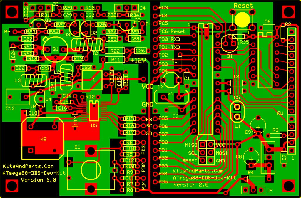
4 General Notes: The DDS Development Kit is fully functional as a Sig_Gen/VFO (once built). the internal firmware currently displays: line1: "DDS Dev Kit V2.0" - (Your callsign can be custom programmed upon request) line2: "nn,nnn.nnn Hz " - (where nn,nnn.nnn is the Frequency) Programmed Frequency range is 1 Hz up to 29,999 khz Operates from 12 VDC at about 110 milliamps Two channels RF output (control line selectable) milliwatts output into a 50 Ω load from 1,800 KHz to 29,999 khz, respectively. Freq range can be changed in firmware. This DDS kit was designed to be a VFO source for NE602A and/or Diode Ring mixers Fully expandable using 20 CPU I/O lines to control other transceiver function. Open Source code available under the GNU General Public License.
5 Quick user manual: Supply power to the DDS using VDC at 120 milliamps current draw. On power-up, the Red LED blinks twice and then the LCD displays 10,000,000 Hz Note there is a cursor under the 1 MHz position on the LCD. Press the encoder and the cursor moves to the 100 KHz position. Each press of the encoder will move the cursor to the right. Pressing the encoder when the cursor is at the 1 Hz position causes the cursor to move to the 10 MHz position. Default Freq is 10 MHz; software programmable. IF OFFSET, both +/-, and band selection via pre-programmed memories will be available soon. 100 MHz CLOCK calibration is available through a special program:
6 Building Instructions: 1. Inventory all Parts The Kit includes two plastic parts bags; one with all the resistors; the other with the remaining parts. The parts bags may contain extra resistors and capacitors that are not used. 1 - PCB manufactured by Resistors (1/4 W) 1-10 Ω R4 Brown - Black - Black - Gold 1-51 Ω R22 Green - Brown - Black - Gold Ω R11 Brown - Red - Brown - Gold Resistors (1/8 W) Ω R21 Orange - Orange - Gold - Gold 2-22 Ω R33,34 Red - Red - Black - Gold 1-51 Ω R20 Green - Brown - Black - Gold 2-75 Ω R31,32 Violet - Green - Black - Gold Ω R2,13,14,29,30 Brown - Black - Brown - Gold Ω R18 Orange - Orange - Gold - Gold
7 Resistors (1/8 W) (cont.) Ω R6,35 Blue - Red - Brown - Gold 4-1 kω R3,19,27,28 Brown - Black - Red - Gold kω R12 Red - Violet - Red - Gold kω R15,16,17 Yellow - Violet - Red - Gold kω R1,5,7,8,9,10,23,24,25,26 Brown - Black - Orange - Gold Capacitors 1-22 pf C3 1-30pF or 40pF - C2 trimmer (green or yellow, respectively) pf C20, pf C nf C10,11,12,27, nf C15,18,23,24,25,29, nf C1,4,5,6,7,14,16,17, nf C μF C8,9 Electrolytic 1 - jumper C19 (instead of a capacitor)
8 Crystal and oscillator MHz crystal X MHz oscillator X2 Semiconductors 1 - ATmega88PA-20 U1 1-74HC164 U U3 1-78L33 U4 1 - AD9834CRUZ U5 1-2N5109 transistor Q1 2-2N3904 transistor Q2,3 1 - red LED D1 2 - MPN3700 PIN diode D2,3 Ferrites 1 - BN L1 inductor/filter 4 turns 1 - BN T1 transformer 6 turn : 3 turn 1 - FT37-43 T2 transformer 8+8 turn (bifilar) 2 - T30-6 L2,3 filter cores 8 turn 16 inches of 26 gage magnet wire 16 inches of 30 gauge magnet wire (dual twisted wires)
9 Miscellaneous 1 - Rotary Encoder E1 1 - RESET pushbutton S pin socket 1-2x3 Program Header J1 3-3-pin power header J2,3, pin LCD socket 1-16-pin LCD header USER SUPPLIED PARTS: three (3) feet of hookup wire 3-pin female connector for power input connection 3-pin female connector for receive RF output connection 3-pin female connector for transmit RF output connection 2. Install all 1/4 Watt Resistors. Note: Bend the resistor leads a sharp 90 degrees from the body R4: 10 Ω Brown - Black - Black - Gold R11: 120 Ω Brown - Red - Brown - Gold R22: 51 Ω Green - Brown - Black - Gold
10 3. Install all 1/8 Watt Resistors. Note: Bend the resistor leads a sharp 90 degrees from the body R1,5,7,8,9,10,23,24,25,26: 10 kω Brown - Black - Orange - Gold R2,13,14: 100 Ω Brown - Black - Brown - Gold R3,19,27,28: 1 kω (1K0) Brown - Black - Red - Gold R6,35: 620 Ω Blue - Red - Brown - Gold R12: 2.7 kω (2K7) Red - Violet - Red - Gold R15,16,17: 4.7 kω (4K7) Yellow - Violet - Red - Gold R18: 330 Ω Orange - Orange - Brown - Gold R20: 51 Ω Green - Brown - Black - Gold R21: 3.3 Ω (3R3) Orange - Orange - Gold - Gold Note: If the DDS Receive output drives a +7dBM Diode Ring Mixer then place a jumper wire at R31 else if the DDS Receive output drives a 602 Gilbert Cell Mixer then install resistors R29,31,33 else design your own Receive output level resistor pad. R29: 100 Ω Brown - Black - Brown - Gold R31: 75 Ω Violet - Green - Black - Gold R33: 22 Ω Red - Red - Black - Gold
11 Note: If the DDS Transmit output drives a +7dBM Diode Ring Mixer then place a jumper wire at R32 else if the DDS Transmit output drives a 602 Gilbert Cell Mixer then install resistors R30,32,34 else design your own Transmit output level resistor pad. R30: 100 Ω Brown - Black - Brown - Gold R32: 75 Ω Violet - Green - Black - Gold R34: 22 Ω Red - Red - Black - Gold 4. Install three 14 pin DIP sockets. Position the socket notches at PIN-1/14 and solder. 5. Install the MHz Crystal about 1/32 inch above the PCB. Insert the Crystal in the PCB and tilt it; hold with one finger and solder. Straighten the XTAL. 6. Install the following capacitors on the digital side (right side) of the PCB. C1,4,5,6,7: 100n yellow axial lead bypass capacitors C2: 40p yellow trimmer capacitor; FLAT SIDE toward C1 (picture shows a green trimmer) C3: 22p NPO axial lead capacitor
12 7. Install type 43 ferrite binocular below C5. There are two binoculars in the parts kit; one has rounded corners and is shiny black, the other has sharp corners and is dull black. The shiny, rounded corners ferrite binocular is a type -43; the other is a type -61. Cut 4 inches of 30 GA green wire and insert 4 complete turns through the -43 binocular. One turn is defined are a wire running through BOTH HOLES of the binocular. Strip the insulation off the wires all the way down to the body of the binocular core. Tin the wires. L1: Insert the BN binocular filter inductor (standing up) and solder. 8. Install Red LED at. D1: Red LED; note polarity (flat side) and solder. 9. Install electrolytic capacitors. C8,9: 47uF; note polarity (+) and solder. 10. Install 4 pin reset push putton; note polaririty; only fints one way into the PCB RESET: Insert and solder. 11. Install the 6 pin programming header to the left of C8 Solder.

13 12. Install the 3 terminal voltage regulator in lower right corner of the PCB (not labeled). U3: LM7805AC; note polarity; Metal TAB toward C8; solder. 13. Install the 16-PIN female LCD header on the left side of the PCB Before installing the female LCD header, you might want to consider how and where you want the LCD to display. You may want to make an extension cable by soldering 16 wires between the PCB and the female header. Install and solder both male and female, header and socket. 14. Connect a 3-PIN header at J2 or connect power wires to J2; center pin is +12V (wires are not supplied) +12V + GND wires: solder.

14 15. Apply 12Vdc power to J2 Measure 5 volts across C7; if not 5V then fix the problem before proceeding.
15 16. Install the surface mount DDS chip (optionally installed by kitsandparts) *** Please be carefull installing the AD9834 *** Align the chip on the SMT pad, PIN-1 toward R12. Tack solder one corner of the DDS chip. Solder the remaining pins to the SMT pad. Use solder wick to remove solder shorts. Review soldering mess using high power magnifying glass, optionally check for shorts using ohm meter. AD9834CRUZ 17. Install type 61 ferrite binocular above R12. There are two binoculars in the parts kit; one has rounded corners and is shiny black, the other has sharp corners and is dull black. The shiny, rounded corners ferrite binocular is a type -43; the other is a type -61. Cut 8 inches of 30 GA red wire and insert 6 complete turns through the -61 binocular. The binocular holes are small so make sure the turns are tight to allow additional winding to be added. One turn is defined as one wire running through BOTH HOLES of the binocular in a U patern. Cut 4 inches of 30 GA green wire and insert 3 complete turns through the -61 binocular.

16 The completed transformer should have 2 red wires coming out one end of the binocular and 2 green wires on the other end. Strip the insulation off the wires all the way down to the body of the binocular core. Tin the wires. L1: Insert the BN binocular transformer (red wires toward R13), pull leads tight and solder. 18. Install the following capacitors on the DDS side (left side) of the PCB. Note that C15 is labeled twice (in error) on the PCB. C15 in the next step is between C14 and C16. C15,18,23,24,25,29,30: 47n yellow axial lead capacitors Install a jumper (discarded resistor lead) at location labeled C15 between R13 and R14 C14,16,17,26: 100n yellow axial lead capacitors C10,11,12,27,28: 10n yellow radial lead disk capacitors

17 19. Install T2, a bifilar wound transformer. Prepare 8 inches of 30 GA dual red/green magnet wire. Twist tightly to about 4 twists per inch. Wind 8 turns, evenly and tight through the body of the FT37-43 ferrite toroid. Trim leads to about half inch from the toroid body. Remove insulation up to the body of the ferrite. It is required that one colored wire is installed in the upper right corner connected to C25 and the other colored wire is connected in the lower left corner connected to the collector of Q1. The remaining red and green wires run through the holes connecting to R19 and the PIN diodes. FT37-43 Strip and Tin leads; and install. 20. Install two T30-6 yellow toroid inductors (low pass filter cores). Prepare 2 pieces of 7 inches of 26 GA red magnet wire. Wind 8 turns of the wire through one yellow toroid. Repeat for the other toroid. Strip the insulation off the wires all the way down to the body of the toroid cores. Tin the wires. L2,3: Install the T37-6 toroids (standing up) and solder.
18 21. Install large yellow capacitor and 3.3 volt regulator C13: 330n yellow radial lead capacitor U4: 78L33-3 terminal voltage regulator; observe polarity 22. Install low pass filter capacitors C20,22: 100p C21: 220p 23. Install semiconductors Q1: 2N install about 1/16 inch or 2 mm above the PCB. Q2,3: 2N install with about 1/4 inch or 6 mm leads above the PCB. Observe polarity and do not overheat. D2,3: MPN install the PIN diodes all the way against the PCB. Observe polarity and do not overheat. 24. Install the 100 MHz Clock X2: 100 MHz - observe polarity; Squared corner points toward the lower left corner of the PCB 25. Install the Rotary Mechanical Encoder, a pulled part recycled from a Panasonic AM/FM Auto Radio. E1: Solder
19 26. Install the power connection jumpers between the DDS and CPU sections of the PCB The following step installs jumpers but could be replaced with inductors to possibly reduce circuit noise. VCC: Install a jumper at VCC located in the center of the PCB and to the left of the trimmer capacitor. GND: Install a jumper at GND located at the lower left of the crystal. 27. Connect the DDS section to the CPU section (a total of six (6) wire jumpers) These connections are firmware dependent. Current firmware requires the following connections: PD4: Connect PD4 from the Encoder to PD4 on the ATmel CPU. PD2: Connect PD2 from the Encoder to PD2 on the ATmel CPU. PD3: Connect PD3 from the Encoder to PD3 on the ATmel CPU. PD5: Connect SD from the AD9834 to PD5 on the ATmel CPU. PD1: Connect SC from the AD9834 to PD1 on the ATmel CPU. PD0: Connect FS from the AD9834 to PD0 on the ATmel CPU. 28. Install the ICs; before inserting the ICs into their sockets, bend the IC pins so that they are at sharp right angles to the IC`s plastic body. The easiest way to bend all leads uniformly is to place the IC legs on a flat table and push/press the body of the IC against the table. DO both sides.
20 U1: ATmega88PA-20 - install observing PIN-1 polarity U2:74HC164 - install observing PIN-1 polarity 29. Connect the LCD to the PCB. OK 30. Momentarily connect 12 volt power to the PCB, observing current draw (if possible) Current consumption should be about 120 milliamps. When the DDS powes up, the LED should flash twice and then the LCD should display 10,000,000 Hz. If all is OK at this point, connect 12 volts to either the TRANSMIT or RECEIVE control lines and measure/view 10 MHz output from the corresponding TRANSMIT or RECEIVE outputs at J3/4. Output level into a 50 ohm dummy load should be about 4.8 volts Peak-to-Peak at 10 MHz, provided that there is no resistor pad in the output section on the PCB. OK

21 31. Assuming that all is OK to this point, the next step is to set up the DDS as a development platform. This step is optional; not required if you plan to use the DDS Kit as a Sig_Gen or VFO. Click on the Development Platform Link for information to update and/or modify the firmware.
Ten Tec DDS Board Assembly Procedure
 05 May 2014 Ten Tec DDS Board Assembly Procedure You will find a photo of a completed board at the end of these instructions. Refer it whenever clarification is required. 1. AD9835 Attachment If you purchased
N3ZI Kits General Coverage Receiver, Assembly & Operations Manual (For Jun 2011 PCB ) Version 3.33, Jan 2012
 Version 3.33, Jan 2012") N3ZI Kits General Coverage Receiver, Assembly & Operations Manual (For Jun 2011 PCB ) Version 3.33, Jan 2012 Thank you for purchasing my general coverage receiver kit. You can use the photo above as a
N3ZI Kits General Coverage Receiver, Assembly & Operations Manual (For Jun 2011 PCB ) Version 3.33, Jan 2012 Thank you for purchasing my general coverage receiver kit. You can use the photo above as a
SoftRock v6.0 Builder s Notes. May 22, 2006
 SoftRock v6.0 Builder s Notes May 22, 2006 Be sure to use a grounded tip soldering iron in building the v6.0 SoftRock circuit board. The soldering iron needs to have a small tip, (0.05-0.1 inch diameter),
SoftRock v6.0 Builder s Notes. April 6, 2006
 SoftRock v6.0 Builder s Notes April 6, 006 Be sure to use a grounded tip soldering iron in building the v6.0 SoftRock circuit board. The soldering iron needs to have a small tip, (0.05-0. inch diameter),
Kits and Parts dot Com Supplying Toroids, Electronic Parts and Kits to Engineers, Schools and Hobbyists
 Kits and Parts dot Com Supplying Toroids, Electronic Parts and Kits to Engineers, Schools and Hobbyists Home Capacitors PA3AKE Filters W3NQN Filters WA2EBY ToroidKit Inductors MagnetWire Information Parts
SoftRock v5.0 Builder s Notes. December 12, Building a QSD Kit
 SoftRock v5.0 Builder s Notes December 12, 2005 Building a QSD Kit Be sure to use a grounded tip soldering iron in building the QSD board. The soldering iron needs to have a small tip, (0.05-0.1 inch diameter),
WA3RNC 30 METER CRYSTALPLEXER TRANSMITTER KIT ASSEMBLY INSTRUCTIONS
 WA3RNC 30 METER CRYSTALPLEXER TRANSMITTER KIT ASSEMBLY INSTRUCTIONS Description The WA3RNC 30 Meter Crystalplexer is a low power crystal controlled QRP transmitter offering a significantly improved tuning
Stand Alone VXO (SAVXO) Assembly Manual Manual Version 1.0B_
 Assembly Manual Manual Version 1.0B_") Stand Alone VXO (SAVXO) Assembly Manual Manual Version.0B_0-6-0 Designed by: Jim Kortge, K8IQY Kitted & Sold by: 4 State QRP Group Copyright: 0 Forward Thank you for purchasing a 4 State QRP Group Stand
Stand Alone VXO (SAVXO) Assembly Manual Manual Version.0B_0-6-0 Designed by: Jim Kortge, K8IQY Kitted & Sold by: 4 State QRP Group Copyright: 0 Forward Thank you for purchasing a 4 State QRP Group Stand
Building a Bitx20 Version 3
 Building a Bitx20 Version 3 The board can be broken into sections and then built and tested one section at a time. This will make troubleshooting easier as any problems will be confined to one small section.
Hendricks QRP Kits The Twofer Rev
 Hendricks QRP Kits The Twofer Rev 1 11-15-06 1. Description The Twofer is a classic QRP transmitter that s easy to assemble and operate. It uses a JFET VXO (variable crystal oscillator), driver stage and
S-Pixie QRP Kit. Student Manual. Revision V 1-0
 S-Pixie QRP Kit Student Manual Revision V 1-0 Introduction The Pixie 2 is a small, versatile radio transceiver that is very popular with QRP (low power) amateur radio operators the world over. It reflects
Assembly Instructions for the 1.5 Watt Amplifier Kit
 Assembly Instructions for the 1.5 Watt Amplifier Kit 1.) All of the small parts are attached to a sheet of paper indicating both their value and id. 2.) Leave the parts affixed to the paper until you are
Building and Operating: LF Converter An SA612 based LF up-converter from Jackson Harbor Press
 Introduction: Building and Operating: LF Converter An SA612 based LF up-converter from Jackson Harbor Press The frequencies below the broadcast band are covered by few receivers on the market - those that
Assembly Manual for VFO Board 2 August 2018
 Assembly Manual for VFO Board 2 August 2018 Parts list (Preliminary) Arduino 1 Arduino Pre-programmed 1 Faceplate Assorted Header Pins Full Board Rev A 10 104 capacitors 1 Rotary encode with switch 1 5-volt
V6.2 SoftRock Lite Builder s Notes. November 17, 2006
 V6.2 SoftRock Lite Builder s Notes November 17, 2006 Be sure to use a grounded tip soldering iron in building the v6.2 SoftRock circuit board. The soldering iron needs to have a small tip, (0.05-0.1 inch
Read This Page First
 Read This Page First If you are reading this you know the manuals are always available at QRPKITS.com. This is version 8.0 of the manual dated 4/27/2016. There is no need to print out the whole assembly
Digital Electronics & Chip Design
 Digital Electronics & Chip Design Lab Manual I: The Utility Board 1999 David Harris The objective of this lab is to assemble your utility board. This board, containing LED displays, switches, and a clock,
HT-1A Dual Band CW QRP Transceiver. Kit Building Instructions
 HT-A Dual Band CW QRP Transceiver Kit Building Instructions Rev B, July 8, 08 Designed by BD4RG Exclusively distributed by CRKITS.COM and its worldwide distributors Join the group http://groups.io/g/crkits
DDS VFO 2 CONSTRUCTION MANUAL. DDS VFO 2 Construction Manual Issue 1 Page 1
 DDS VFO 2 CONSTRUCTION MANUAL DDS VFO 2 Construction Manual Issue 1 Page 1 Important Please read before starting assembly STATIC PRECAUTION The DDS VFO kit contains the following components which can be
KN-Q10 Assembly Manual
 KN-Q10 Assembly Manual Translated by Adam Rong, BD6CR/4 with permission from Ke Shi, BA6BF Edited by Stephen, VK2RH Revision B, Oct 14, 2010 Thank you for purchasing the KN-Q10 4 Band SSB/CW Dual Mode
Read This Page First
 Read This Page First If you are reading this you know the manuals are always available at QRPKITS.com. If you have questions contact qrpkits.com@gmail.com There is no need to print out the whole assembly
Easy Transmitter. Support ETX_REV5_Manual V2.7 Revised
 Easy Transmitter Introduction The Easy Transmitter kit from qrpkits.com provides a basic, crystal controlled transmitter with VXO tuning to provide a small tuning range around the crystal frequency. It
Blue Ring Tester Kit Assembly & User Manual
 Blue Ring Tester Kit Assembly & User Manual Alltronics LLC/AnaTek Instruments 2761 Scott Blvd, Santa Clara, CA, 95050, USA March 2015 Edition Tel: 408-778-3868, Fax: 408-778-2558, E mail : tech@alltronics.com
The Walford Electronics Ford Receiver Kit Project Construction Manual
 The Walford Electronics Ford Receiver Kit Project Construction Manual Walford Electronics Ford Receiver construction manual V1.5 Page 1 of 22 Introduction The Ford receiver has four stages: The first stage
Penrose Quantizer Assembly Guide
 Penrose Quantizer Assembly Guide Schematic and BOM The schematic can be found here: www.sonic-potions.com/public/penrosequantizerschematic.pdf The BOM is available at google docs: Link to BOM Prepare the
Pacific Antenna Easy TR Switch
 Pacific Antenna Easy TR Switch Kit Description The Easy TR Switch is an RF sensing circuit with a double pole double throw relay that can be used to automatically switch an antenna between a separate receiver
QRPGuys Michigan Mighty Might Plus 40M Transmitter
 QRPGuys Michigan Mighty Might Plus 40M Transmitter First, familiarize yourself with the parts and check for all the components. If a part is missing, please contact us and we will send one. You must use
PM24 Installation Instructions
 Marchand Electronics Inc. PO Box 473, Webster, NY 14580 Tel:(716) 872-0980 Fax:(716) 872-1960 info@marchandelec.com http://www.marchandelec.com (c)1997 Marchand Electronics Inc. PM24 Installation Instructions
Arizona ScQRPion QRP Club. Ft Tuthill w DC CW Transceiver for 80m Part 1 of 2. by Dan Tayloe, N7VE. Ft Tuthill Page 1 of 31
 Arizona ScQRPion QRP Club Ft Tuthill 80 2.5w DC CW Transceiver for 80m Part 1 of 2 by Dan Tayloe, N7VE Page 1 of 31 Table of Contents Specifications... 4 Specifications... 4 Receiver... 4 Transmitter...
IR add-on module circuit board assembly - Jeffrey La Favre January 27, 2015
 IR add-on module circuit board assembly - Jeffrey La Favre January 27, 2015 1 2 For the main circuits of the line following robot you soldered electronic components on a printed circuit board (PCB). The
Pacific Antenna Easy Transmitter Kit
 Pacific Antenna Easy Transmitter Kit Introduction The Easy Transmitter kit from qrpkits.com provides a crystal controlled transmitter with VXO tuning. The circuit consists of a N3904 based crystal oscillator
10W HF Linear PA. A low-cost, high-performance HF Linear PA covering 2-30MHz. 10W HF Linear Power Amplifier kit assembly manual
 10W HF Linear PA 10W HF Linear Power Amplifier kit assembly manual A low-cost, high-performance HF Linear PA covering 2-30MHz Designed and produced by QRP Labs, 2018 10W HF Linear PA kit assembly 1.01
Dual Band Filter Assembly Manual
 Dual Band Filter Assembly Manual 12 January 2018 Rev D Version Theory of Operation: The purpose of a Bandpass Filter is to filter out or reject all unwanted signals. The original KN-Q7A Receive Filter
16 Bit Micro Experimenter Assembly and Check out Instructions
 16 Bit Micro Experimenter Assembly and Check out Instructions The kit you purchased that includes PCB, schematic, complete parts list and these assembly instructions. A top picture of the complete assembly
PM124 Installation Instructions. See important note about revisions of this board on the last page.
 Marchand Electronics Inc. PO Box 473, Webster, NY 14580 Tel:(716) 872-0980 Fax:(716) 872-1960 info@marchandelec.com http://www.marchandelec.com (c)1997 Marchand Electronics Inc. PM124 Installation Instructions
ALX-SSB Transceiver Kit Assembly Manual
 ALX-SSB Transceiver Kit Assembly Manual 20 August 2018 REV A Transceiver This radio is based on the popular CS-Series SSB Transceiver Kit developed by Adam Rong, BD6CR/4 CRKITS.com. Thanks to B. Bartosh
LED Field Strength Indicator Kit
 LED Field Strength Indicator Kit Description The Field Strength Indicator kit from Qrpkits.com provides a visual way to monitor RF fields through the brightness of an LED. It will respond to RF fields
TekBot Remote Control Receiver Board Construction
 TekBot Remote Control Receiver Board Construction Purpose This tutorial illustrates the procedure for construction of the Receiver board for the TekBot. A Guide to Soldering Many of you have soldered once
Building the Sawdust Regenerative Receiver
 Building the Sawdust Regenerative Receiver Introduction The Sawdust is a super regenerative receiver using the basic Armstrong design architecture. The receiver uses one toroidal transformer to provide
Pacific Antenna - Easy TR Switch
 Pacific Antenna - Easy TR Switch Kit Description The Easy TR Switch is an RF sensing switch that can be used to switch an antenna between a receiver and transmitter. It also has a second switched pair
Simple LFO Features. 2. Application. 3. Description. Simple and easy to build LFO module for Analog Synthesizers.
 Simple LFO. Simple and easy to build LFO module for Analog Synthesizers.. Features Square and Triangle waveforms (90 phase shifted) Dual range frequencies Frequency ranges from under Hz up to several khz
Read This Page First
 Pacific Antenna 0 Watt HF Amplifier Kit Manual This is Version 5.5 dated 060505 Read This Page First If you are reading this you know the manuals are always available at QRPKITS.com. If you have questions
Bill of Materials: General Purpose Alarm, Pulsed PART NO
 General Purpose Alarm, Pulsed PART NO. 2190207 I hate alarms that sound continuously - unless they are smoke alarms. Smoke alarms should be annoying, but others should not. I wanted an alarm for a function
Assembly Instructions
 Assembly Instructions For the SSQ-2F 3.1 MHz Rife Controller Board Kit v1.41 Manual v1.00 2012 by Ralph Hartwell Spectrotek Services GENERAL ASSEMBLY INSTRUCTIONS Arrange for a clean work surface with
QRPGuys SMT Digital Dial/Frequency Counter
 QRPGuys SMT Digital Dial/Frequency Counter First, familiarize yourself with the parts and check for all the components. If a part is missing, please contact us and we will send one. You must use qrpguys.parts@gmail.com
Assembly Instructions for the FRB FET FM 70 Watt Amp
 Assembly Instructions for the FRB FET FM 70 Watt Amp 1.) Orient the circuit board with the diagram 2.) Use a narrow chisel tip 25-30 watt soldering iron for assembly 3.) All the small parts are taped onto
DEM Part Number L144-28INTCK 144 MHz Transverter Kit and complete kit
 DEM Part Number L144-28INTCK 144 MHz Transverter Kit and complete kit Power Out: Noise Figure and Gain: DC Power Requirement: 50 mw linear minimum 3.5 db NF nominal, 5 dbg maximum 12-15.5 VDC, 13.8 nominal
Assembly Manual V1R2B-Rev1.0D
 Assembly Manual V1R2B-Rev1.0D for 4 State QRP MagicBox - Solid State Transmit/Receive System Designed by: Jim Kortge, K8IQY Copyright 2009-2012 - All rights reserved This system is the result of some brainstorming
Wiring Manual NEScaf April 2010 (August 2006)
") Wiring Manual NEScaf April 2010 (August 2006) Switched Capacitor Audio Filter The NEScaf is a switched capacitor audio filter (acronym SCAF) built around a building-block type filter chip. The NEScaf will
Wiring Manual NEScaf April 2010 (August 2006) Switched Capacitor Audio Filter The NEScaf is a switched capacitor audio filter (acronym SCAF) built around a building-block type filter chip. The NEScaf will
FM Audio/Squelch Board by Steve Dold, W6KCS w6kcs (at) stevedold (dot) com
 stevedold (dot) com") FM Audio/Squelch Board by Steve Dold, W6KCS w6kcs at stevedold dot com Board hardware version 7-8 Firmware version 7.x This board connects to an FM receiver's discriminator/detector and provides squelched,
FM Audio/Squelch Board by Steve Dold, W6KCS w6kcs at stevedold dot com Board hardware version 7-8 Firmware version 7.x This board connects to an FM receiver's discriminator/detector and provides squelched,
Enhancing Your QRP Operating Enjoyment
 QRP-DWM Directional-Coupler Watt Meter Preliminary By: W5USJ CyM-Tech Documentation Services Enhancing Your QRP Operating Enjoyment PCB Assembly Top View Addendum: Correct missing toroid ground after installing
ALX-SSB 5 Band Filter Assembly Manual 19 November 2018
 ALX-SSB 5 Band Filter Assembly Manual 19 November 2018 Contents Theory of Operation:... 1 Figure 1... 2 Parts Included:... 4 Board Overview:... 5 Figure 2... 5 Figure 3... 5 Board Assembly:... 6 Cable
12V Dimmer Kit, version 2
 12V Dimmer Kit, version 2 User Manual Description The 12V Dimmer Kit V2 is an especially efficient PWM (pulse-width modulation) controller for 12V loads up to 60 watts. It features a single dial control
DIODE / TRANSISTOR TESTER KIT
 DIODE / TRANSISTOR TESTER KIT MODEL DT-100K 99 Washington Street Melrose, MA 02176 Phone 781-665-1400 Toll Free 1-800-517-8431 Visit us at www.testequipmentdepot.com Assembly and Instruction Manual Elenco
Building the Sawdust Regenerative Receiver
 Building the Sawdust Regenerative Receiver Introduction The Sawdust is a super regenerative receiver using the basic Armstrong design architecture. The receiver uses one toroidal transformer to provide
SUPER Tuna ][+ Builder s Guide
![SUPER Tuna ][+ Builder s Guide](/thumbs/72/66369453.jpg "SUPER Tuna ][+ Builder s Guide") SUPER Tuna ][+ Builder s Guide Ver2.3 Rex Harper W1REX 3/25/2015 The first thing you should do is to familiarize yourself with what you are going to build. The previous 3 pages are schematics of the
SUPER Tuna ][+ Builder s Guide Ver2.3 Rex Harper W1REX 3/25/2015 The first thing you should do is to familiarize yourself with what you are going to build. The previous 3 pages are schematics of the
Pacific Antenna Field Strength Indicator Kit
 Pacific Antenna Field Strength Indicator Kit Description The Field Strength Indicator kit from Pacific Antenna provides a visual way to monitor the presence and relative strength RF fields through the
LITTLE NERD v1.1 Assembly Guide
 last update: 9. 3. 2016 LITTLE NERD v1.1 Assembly Guide bastl instruments.com INTRODUCTION This guide is for building Little Nerd module from Bastl Instruments. It is good to have basic soldering skills
DIODE / TRANSISTOR TESTER KIT
 DIODE / TRANSISTOR TESTER KIT MODEL DT-100K Assembly and Instruction Manual Elenco Electronics, Inc. Copyright 1988 Elenco Electronics, Inc. Revised 2002 REV-K 753110 DT-100 PARTS LIST If you are a student,
Tek-Bot Remote Control Transmitter Board Construction
 Tek-Bot Remote Control Transmitter Board Construction Purpose This tutorial illustrates the procedure for construction of the Transmitter board for the Tek-bot. A Guide to Soldering Many of you have soldered
Circuit Board Assembly Instructions for Babuinobot 1.0
 Circuit Board Assembly Instructions for Babuinobot 1.0 Brett Nelson January 2010 1 Features Sensor4 input Sensor3 input Sensor2 input 5v power bus Sensor1 input Do not exceed 5v Ground power bus Programming
Building and Operating: Son of Zerobeat A PIC based CW zerobeat indicator from Jackson Harbor Press
 Building and Operating: Son of Zerobeat A PIC based CW zerobeat indicator from Jackson Harbor Press Ed Nisley, KE4ZNU, wrote an article published in the August, September and October of 1996 issues of
Building The DC Beeper from Jackson Harbor Press A Morse code voltmeter / DC switch
 Building The DC Beeper and from Jackson Harbor Press Operating A Morse code voltmeter / DC switch The DC Beeper kit is a combination of a Morse code voltmeter with 20 mv resolution and a DC switch. The
4ms SCM Breakout. Kit Builder's Guide for PCB v2.1 4mspedals.com
 4ms SCM Breakout Kit Builder's Guide for PCB v2.1 4mspedals.com Shuffling Clock Multiplier Breakout This guide is for building a Shuffling Clock Multiplier Breakout module (SCMBO) version 2.1 from the
Circuit Board Assembly Instructions
 Circuit Board Assembly Instructions This document walk you through the assembly of the Base4 Clock v1.2 - v1.3 circuit boards. Important note for kit buyers The color and appearance of the components may
Ultimate3S: Multi-mode QRSS/WSPR transmitter kit. PCB Revision: QCU Rev 3
 Ultimate3S: Multi-mode QRSS/WSPR transmitter kit 1. Introduction PCB Revision: QCU Rev 3 Thank you for purchasing this QRP Labs kit. You will also plug in other modules. You need to download assembly instructions
Bitx Version 3 Linear Amplifier Assembly
 Bitx Version 3 Linear Amplifier Assembly The power supply section has 2 options. 1 - AC input and a higher voltage on the IRF510 and +12 volts to the bitx. 2 - +12 volts applied to both the final and the
HW-8-TR V3 PARTS LIST
 HW-8-TR V3 PARTS LIST Qty Ref Description Markings 4C2 C3 C4 C5 Capacitor Disc.1ls.1uF 104 1 C1 Capacitor Disc.2ls.1uF 100V 104 1 QSKMOD-C92 Capacitor Electrolytic 1uF 50V 1 QSKMOD Capacitor Mylar.47uF
E L E C R A F T K N B 1 N O I S E B L A N K E R
 Introduction E L E C R A F T K N B N O I S E B L A N K E R Assembly and Operating Instructions Revision C, Jan. 8, 200. Copyright 200, Elecraft; All Rights Reserved The KNB noise blanker can be used to
Foxhunt Offset Attenuator. Parts List:
 When your closing in on the fox you may find the signals to be so strong that you can no longer find a peak or null with your antenna. Sometimes the signal is so strong that the RF will leak straight into
Introduction 1. Download socket (the cable plugs in here so that the GENIE microcontroller can talk to the computer)
") Introduction 1 Welcome to the magical world of GENIE! The project board is ideal when you want to add intelligence to other design or electronics projects. Simply wire up your inputs and outputs and away
Introduction 1 Welcome to the magical world of GENIE! The project board is ideal when you want to add intelligence to other design or electronics projects. Simply wire up your inputs and outputs and away
LDB-1 Kit Instructions Page 1 of 8
 LDB-1 Kit Instructions Page 1 of 8 Important Information Congratulations and thank you for your purchase of the LDB-1 Little Drummer Boy Analog Drum Machine Kit! Before you start, please read the enclosed
G11+ GSDR quick start assembly manual [Part 2]
![G11+ GSDR quick start assembly manual [Part 2]](/thumbs/94/119194661.jpg "G11+ GSDR quick start assembly manual [Part 2]") G11+ GSDR quick start assembly manual [Part 2] January 31, 2012 Ver 1.1 Tasa, YU1LM and Nick, VK2DX Overview G11 quick start assembly manual Part 2 covers assembly of the TX components. There are two chapters
G11+ GSDR quick start assembly manual [Part 2] January 31, 2012 Ver 1.1 Tasa, YU1LM and Nick, VK2DX Overview G11 quick start assembly manual Part 2 covers assembly of the TX components. There are two chapters
D.I.Y L.E.D CUBE 4X4X4. Level: Intermediate
 EN D.I.Y L.E.D CUBE 4X4X4 Level: Intermediate AK-125 TABLE OF CONTENTS Parts List... 2 Soldering Guide (Part A)... 3 Soldering Guide (Part B)... 5 Soldering Guide Without Recommend Products... 8 Appendix...
Bill of Materials: PWM Stepper Motor Driver PART NO
 PWM Stepper Motor Driver PART NO. 2183816 Control a stepper motor using this circuit and a servo PWM signal from an R/C controller, arduino, or microcontroller. Onboard circuitry limits winding current,
DIY Function Generator XR2206
 DIY Function Generator XR2206 20Hz 100KHz http://radiohobbystore.com Components List: Resistors: R1, R2 1% Metal Film 5K1 R4 1% Metal Film 10K R5 1% Metal Film 3K R10 5% Carbon Film 10R R3, R9 Potentiometer
Pacific Antenna 10 Watt HF Amplifier Kit
 Pacific Antenna 0 Watt HF Amplifier Kit Description Our 0 watt Linear, HF amplifier kit is designed to increase the power output of low power transmitters. Gives up to 5dB gain and includes an input attenuator
QLG1 GPS Receiver kit
 QLG1 GPS Receiver kit 1. Introduction Thank you for purchasing the QRP Labs QLG1 GPS Receiver kit. This kit will provide a highly sensitive, highly accurate GPS receiver module, using the popular MediaTek
SPACE WAR GUN KIT MODEL K-10. Assembly and Instruction Manual. Elenco Electronics, Inc.
 SPACE WAR GUN KIT MODEL K-10 Assembly and Instruction Manual Elenco Electronics, Inc. Copyright 1989 Elenco Electronics, Inc. Revised 2001 REV-H 753210A PARTS LIST Contact Elenco Electronics (address/phone/e-mail
Building the Toothpick Audio CW Filter
 Building the Toothpick Audio CW Filter Introduction The toothpick is a simple variable bandpass audio filter designed to compliment the Splinter QRPp Trans-Receiver. The filter also contains an audio amplifier
Connecting the FCC-2 to the Hendricks DC Kits Bob Okas, W3CD
 Connecting the FCC-2 to the Hendricks DC Kits Bob Okas, W3CD This is an application note that describes how you can connect the NorCal FCC-1/2 combination to the DC kits. It involves a few extra components
Patton Robotics, LLC.
 Patton Robotics LLC Patton Robotics T3 Motherboard Assembly Instructions Version 1.1 Patton Robotics, LLC. 61 Hagan Drive New Hope, PA 18938 Phone: 609-977-5525 Email: pattonrobotics@gmail.com Copyright
Pacific Antenna 20 and 40M Lightweight Dipole Kit
 Pacific Antenna 20 and 40M Lightweight Dipole Kit Diagram showing configuration and approximate lengths 8 6 16 9 16 9 8 6 Description The Pacific Antenna lightweight dual band, trap dipole kit provides
Pacific Antenna 20 and 40M Lightweight Dipole Kit
 Pacific Antenna 20 and 40M Lightweight Dipole Kit Antenna diagram showing configuration and lengths when assembled 7 8 16 9 16 9 Description The Pacific Antenna lightweight dual band dipole kit provides
SDR Cube Transceiver Online Assembly Guide
 SDR Cube Transceiver Online Assembly Guide Detailed construction notes for building and testing each of the SDR Cube kit modules Home Bill of Materials I/O Board Controls Board DSP Board Softrock SR-Base
LED Infinity Mirror Controller, 32 LEDs, Multiple Patterns.
 http://wwwinstructablescom/id/led-infinity-mirror-controller-32-leds-multiple-/ Food Living Outside Play Technology Workshop LED Infinity Mirror Controller, 32 LEDs, Multiple Patterns by ChromationSystems
Pacific Antenna 20 and 40M Lightweight Dipole Kit
 Pacific Antenna 20 and 40M Lightweight Dipole Kit Diagram showing configuration and approximate lengths 8 3 16 9 16 9 8 3 Description The Pacific Antenna lightweight dual band, trap dipole kit provides
Workshop Part Identification Lecture N I A G A R A C O L L E G E T E C H N O L O G Y D E P T.
 Workshop Part Identification Lecture N I A G A R A C O L L E G E T E C H N O L O G Y D E P T. Identifying Resistors Resistors can be either fixed or variable. The variable kind are called potentiometers
K1EL 75 Meter AM Phone Receiver AMR75
 Features 3.8MHz Amateur Phone Band Receiver 100 KHz Tuning Range Wideband Hi-Fi AM mode reception Single Sideband mode with on board BFO Uses single chip TRF TA7642 IC Low impedance 8 ohm speaker output
Custom Integrated Circuit (MSM9520RS) Replacement Module
 Replacement Module") FT-101Z/ FT-107/ FT-707/ FT-901,902 (later version) DISPLAY COUNTER UNIT (PB-2086A) Custom Integrated Circuit (MSM9520RS) Replacement Module Assembly and Installation Manual (v1.3e) STEP-BY-STEP PROCEDURES
FT-101Z/ FT-107/ FT-707/ FT-901,902 (later version) DISPLAY COUNTER UNIT (PB-2086A) Custom Integrated Circuit (MSM9520RS) Replacement Module Assembly and Installation Manual (v1.3e) STEP-BY-STEP PROCEDURES
Assembly and Operating Instructions. Revision D, Aug. 20, Copyright 2002, Elecraft; All Rights Reserved
 Introduction E L E C R A F T K N B N O I S E B L A N K E R Assembly and Operating Instructions Revision D, Aug. 0, 00. Copyright 00, Elecraft; All Rights Reserved The KNB noise blanker can be used to suppress
FM RADIO KIT ESSENTIAL INFORMATION. Version 2.0 GET IN TUNE WITH THIS
 ESSENTIAL INFORMATION BUILD INSTRUCTIONS CHECKING YOUR PCB & FAULT-FINDING MECHANICAL DETAILS HOW THE KIT WORKS GET IN TUNE WITH THIS FM RADIO KIT Version 2.0 Build Instructions Before you start, take
DuoDrive Nixie Bargraph Kit
 Assembly Instructions And User Guide Nixie Bargraph Kit - 1 - REVISION HISTORY Issue Date Reason for Issue Number 1 12 December 2017 New document - 2 - 1. INTRODUCTION 1.1 About Nixie Bargraph Driver IN-9
HAMTRONICS TB901 FM EXCITER INSTALLATION, OPERATION, & MAINTENANCE
 HAMTRONICS TB901 FM EXCITER INSTALLATION, OPERATION, & MAINTENANCE GENERAL INFORMATION. The TB901 is a single-channel low power fm transmitter (exciter) designed to provide 300-600 milliwatts continuous
Polyphase network kit
 Polyphase network kit 1. Introduction This polyphase network module is designed to be used with the QRP Labs receiver module kit. It takes as inputs, four phase audio from the Quadrature Sampling Detector
Construction Manual 6m-Linear-Transverter XV6/10
 Construction Manual 6m-Linear-Transverter XV6/10 Holger Eckardt DF2FQ Kirchstockacherstr. 33 D-85662 Hohenbrunn 2606 Technical data exciter frequency: 28... 30 MHz RF frequency: 50... 52 MHz supply voltage:
HAMTRONICS LPA 2-25R REPEATER POWER AMPLIFIER: ASSEMBLY, INSTALLATION, & MAINTENANCE
 HAMTRONICS LPA 2-25R REPEATER POWER AMPLIFIER: ASSEMBLY, INSTALLATION, & MAINTENANCE GENERAL INFORMATION. The Power Amplifier is a class C device designed to be installed as an integral part of a transmitter
Time of Arrival Radio Direction Finder.
 Time of Arrival Radio Direction Finder. Time of arrival (TOA) RDF units are simple and very useful. Various designs have been distributed over the years, and here is another one. This Kit Developed by
FUNCTION GENERATOR KIT
 FUNCTION GENERATOR KIT MODEL FG-500K Assembly and Instruction Manual Elenco Electronics, Inc. Copyright 2005 by Elenco Electronics, Inc. All rights reserved. Revised 2005 REV-B 753069 No part of this book
Beta-test ED1 PCB installed in I0CG s K1
 K1 SSB Modification (Ed.2) This description provides the receiver (RX) modifications, assembly, alignment and operation as a first step. In a second step you can add the remaining transmitter (TX) modifications,