Circuit Board Assembly Instructions
|
|
|
- Christopher Gilbert
- 5 years ago
- Views:
Transcription

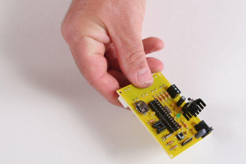
1 Circuit Board Assembly Instructions This document walk you through the assembly of the Base4 Clock v1.2 - v1.3 circuit boards. Important note for kit buyers The color and appearance of the components may vary from one supplier to another and not match exactly the components illustrated in this document. The kit provided for the Kickstarter backers matches the images here with the exception of the ceramic capacitors and one electrolytic capacitor. Some notes have been added to the Parts section when the appearance differ.

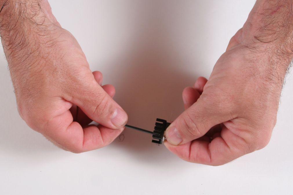
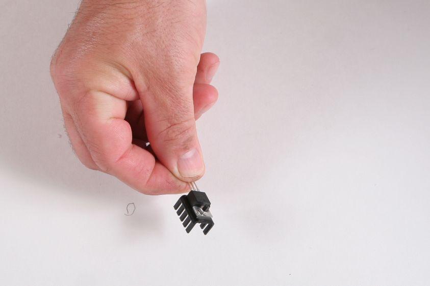
2 Heat Sink Parts Quantity Image HEAT SINK TO " COMPACT 1 IC REG LDO 5V 1.5A TO220 1 Screw the heat-sink to the 7805 voltage regulator.
3

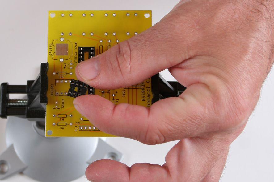
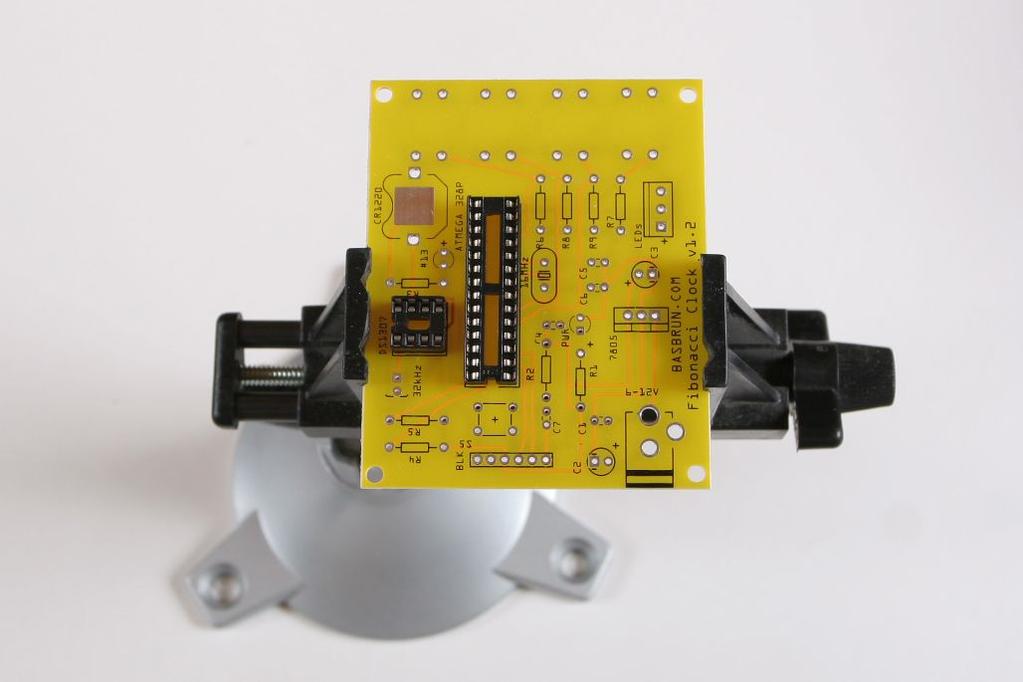
4 DIP Sockets Parts Quantity Image CONN IC DIP SOCKET 28POS TIN 1 CONN IC DIP SOCKET 8POS TIN 1 Place the two DIP sockets in their locations.. The dent at the end of the DIP sockets should align with the dent on the circuit board drawings.
5

6 Secure with tape if necessary. Solder
7

8 Coin Battery Retainer Parts Quantity Image RETAINER COIN 12MM W/PC PINS 1 Snap the coin battery retainer into place. Make sure the opening if facing the edge of the board. Solder

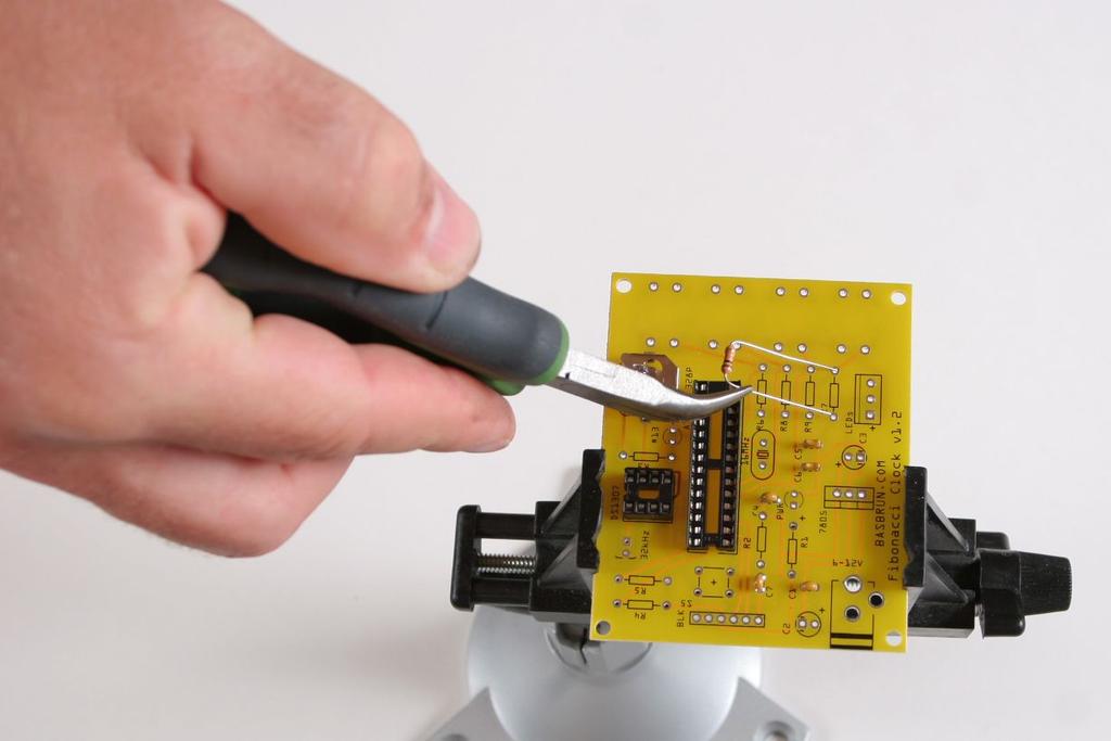
9 Ceramic Capacitors Parts Quantity Image CAP CER 22PF 200V 10% RADIAL 2 May be short yellow in your kit CAP CER 0.1UF 50V 10% RADIAL 3 May be blue in your kit Place the two 22pF capacitors in C5 and C6. These capacitors are non-polarized and can be soldered in either way.
10

11 Place the three 0.1uF capacitors in C1, C4 and C7. These capacitors are non-polarized and can be soldered in either way.
12
13 Solder

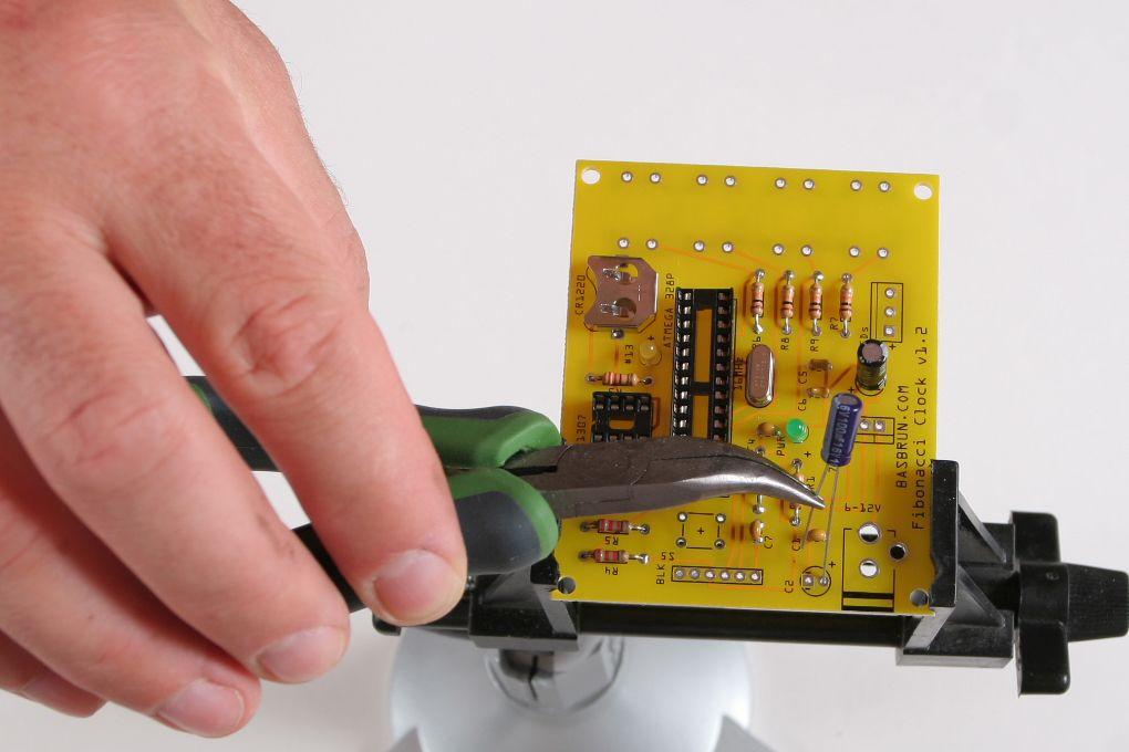
14 Cut the excess wires.

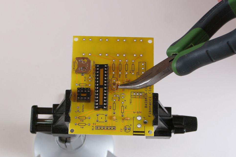
15 Resistors Parts Quantity Image RES 10K OHM 1/4W 5% AXIAL 5 RES 2.2K OHM 1/4W 5% CARBON FILM 2 RES 220 OHM 1/4W 5% AXIAL 2 Place the five 10KH resistors in R2, R6, R7, R8 and R9. Resistors are non-polarized and can be soldered in either way.
16

17 Place the two 220H resistors in R1 and R3. Resistors are non-polarized and can be soldered in either way

18 Place the two 2.2KH resistors in R4 and R5. Resistors are non-polarized and can be soldered in either way
19

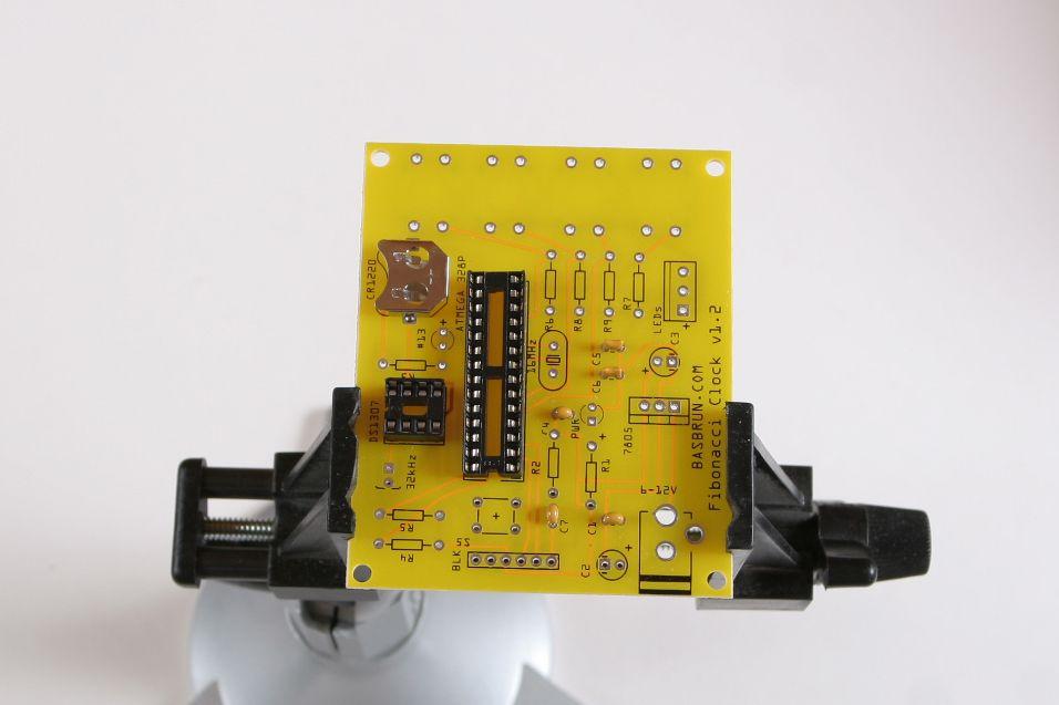
20 Solder Cut the excess wires.

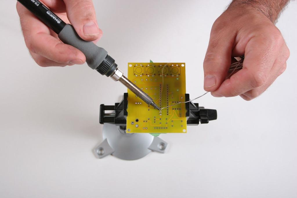
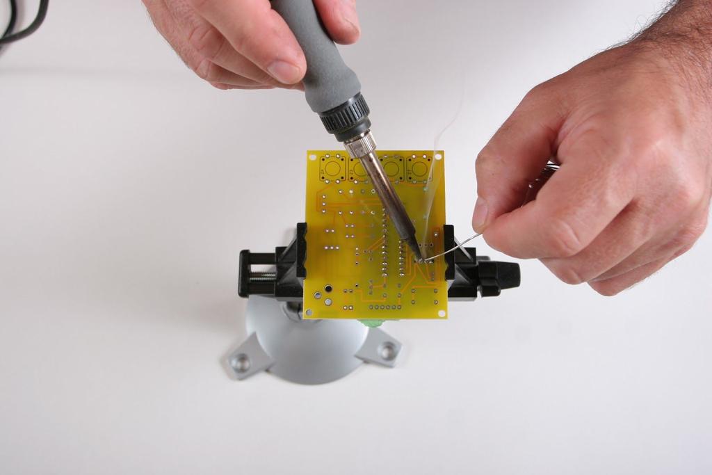
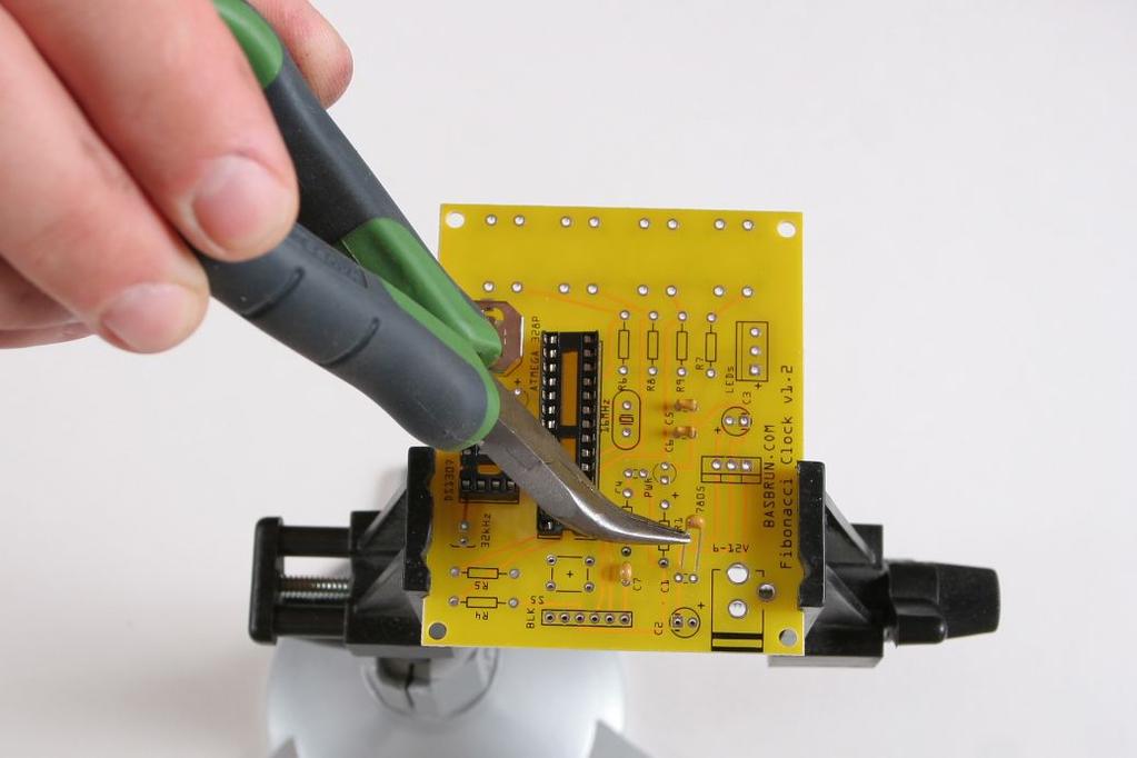
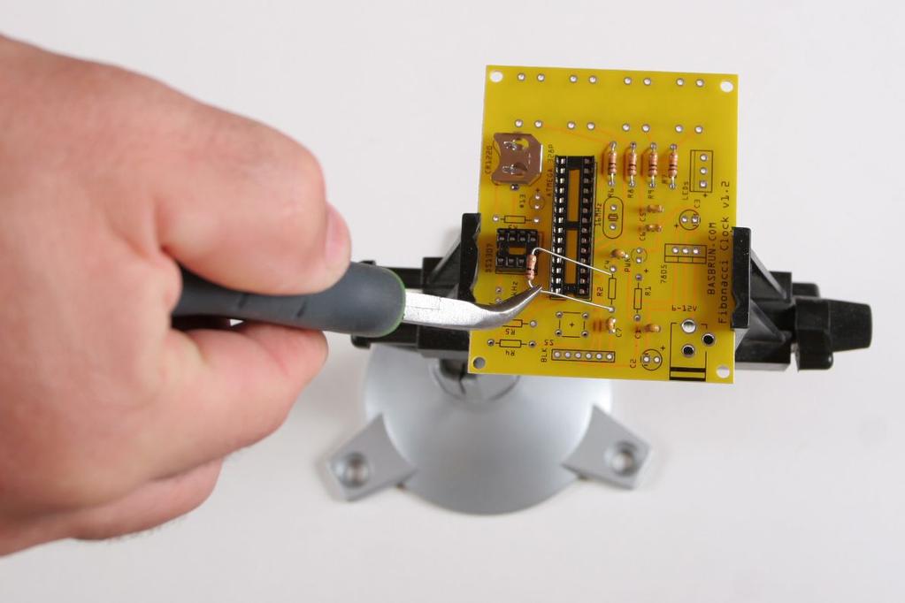
21 Crystals Parts Quantity Image CRYSTAL MHZ 18PF T/H 1 CRYSTAL KHZ 12.5PF T/H 1 Place the 16MHz crystal in it s location next to the Atmega328P DIP socket. Crystals are non-polarized and can be placed in either way.

22 Place the 32KHz crystal in it s place next to the DS1307 DIP socket. Crystals are non-polarized and can be placed in either way. Secure the crystal with tape if necessary.
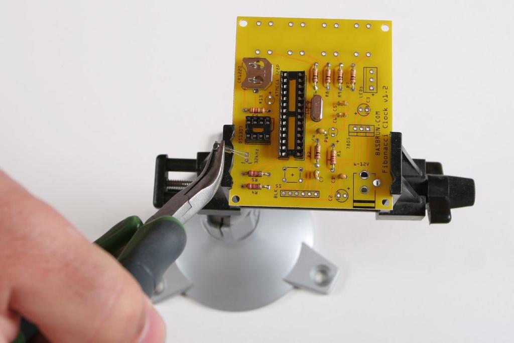
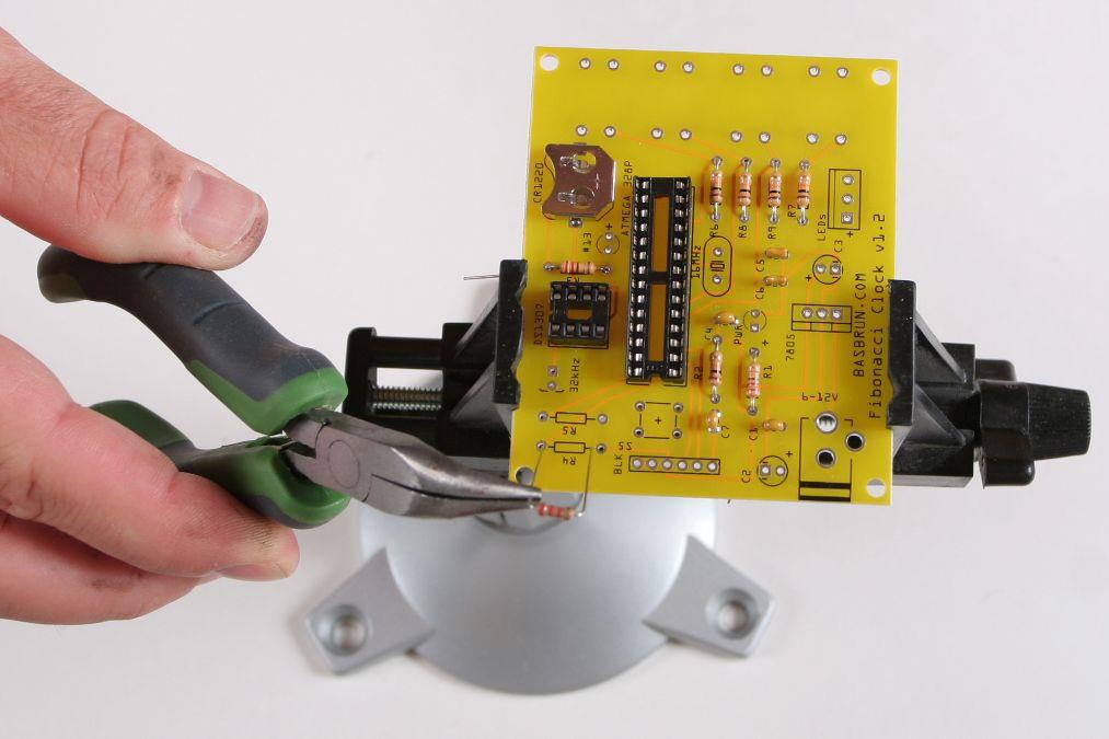
23 Solder

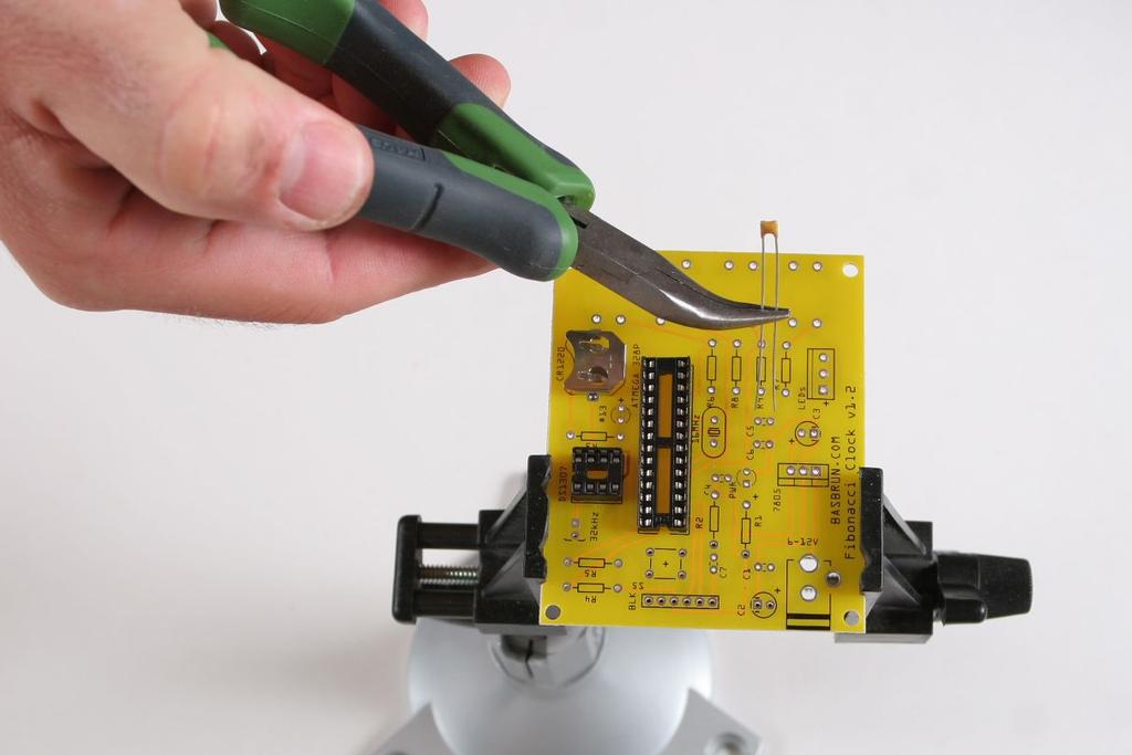
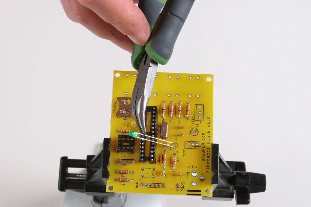
24 Cut the crystal excess wires. LEDs Parts Quantity Image WL-TMRC THT LED ROUND COLOR DIFF 1 LED GRN 572NM DIFF 3MM RND 1 Place the yellow LED in its location close to the battery retainer. Make sure the long wire (anode) is in the hole next to the (+) sign.
 is in the hole next to the (+)")
25 Place the green LED in its location in the center of the board. Make sure the long wire (anode) is in the hole next to the (+) sign.
26

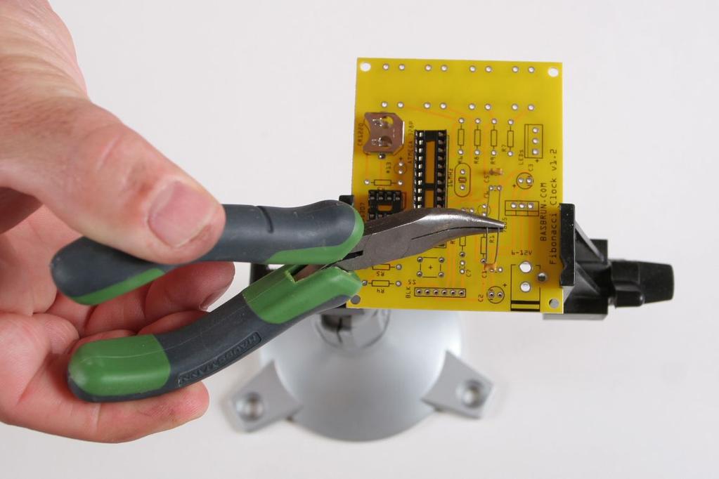
27 Solder Cut the excess wires.
 sign.")
28 Electrolytic Capacitors Parts Quantity Image CAP ALUM 100UF 20% 16V RADIAL 1 CAP ALUM 10UF 20% 25V RADIAL 1 May be blue in your kit Place the 10uF electrolytic capacitors on C3. Electrolytic capacitors are polarized, make sure to insert the long wire into the round hole marked with a (+) sign.
29 Place the 100uF electrolytic capacitors on C2. Electrolytic capacitors are polarized, make sure to insert the long wire into the round hole marked with a (+) sign.
30 Solder

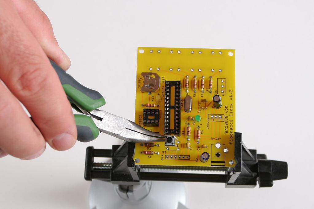
31 Cut the excess wires.

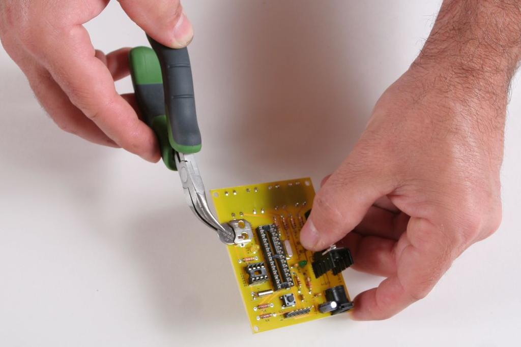
32 Reset Switch Parts Quantity Image SWITCH TACTILE SPST-NO 0.05A 24V 1 Place the reset switch in its location between the Atmega328P DIP socket and the FTDI port. The pins of the switch must be facing the top and bottom sides of the board.
33 Solder

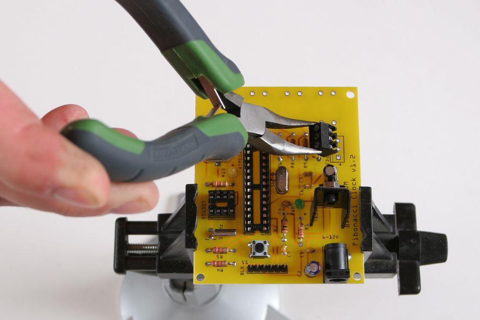
34 FTDI Port Parts Quantity Image CONN HEADER 6POS.100 STR TIN 1 Place the male header with the long pins facing up.

35 Secure with tape.

36 Solder the male header. [NO IMAGE] Power Connector Parts Quantity Image CONN POWER JACK 2.1MM 1 Place the power connector in its location and secure with tape if necessary.
37 Solder

38 Voltage Regulator Parts Quantity Image HEAT SINK TO " COMPACT 1 IC REG LDO 5V 1.5A TO220 1 Place the voltage regulator and heat-sink assembly in the place marked The heat-sink should face the power connector.
39 Solder

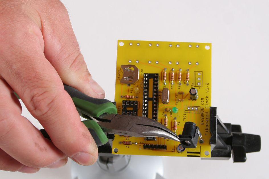
40 Cut the excess wires.

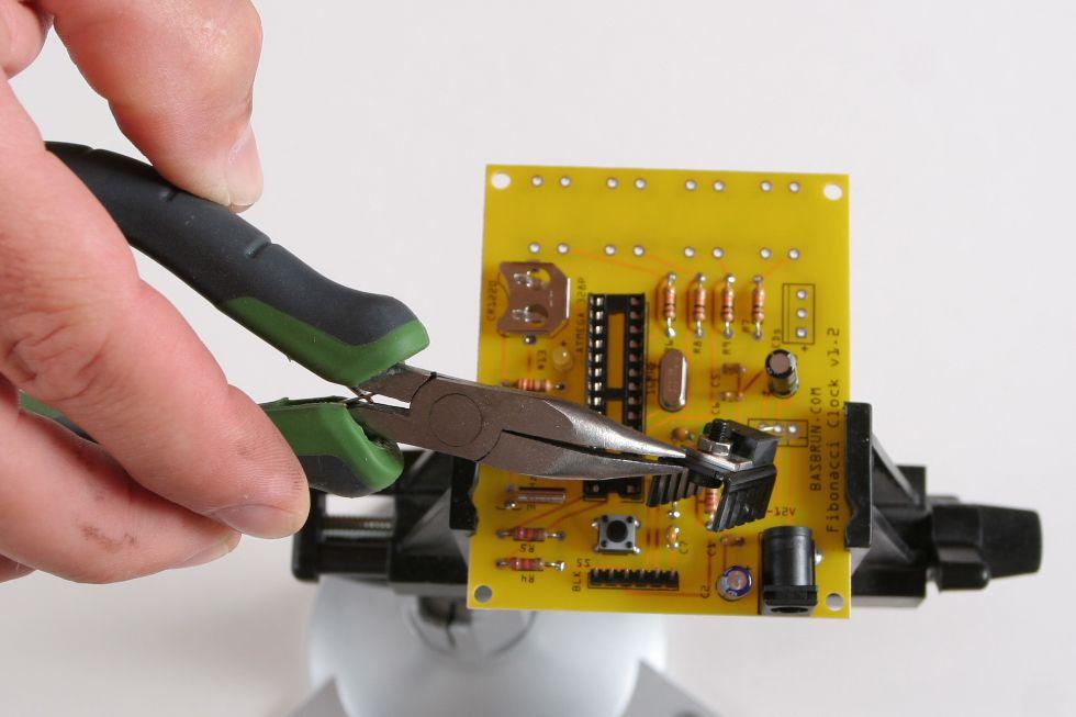
41 Terminal Block Parts Quantity Image TERMINAL BLOCK 3.5MM 3POS PCB 1 Place the terminal block on the board with the beveled side facing the bottom edge of the board. Secure the part with tape if necessary.
42 Solder

43 Clock Buttons Parts Quantity Image SWITCH TACTILE SPST-NO 0.05A 24V 4 May be all black in your kit Turn the board on the other side and place the four buttons in their location. They should snap in place.
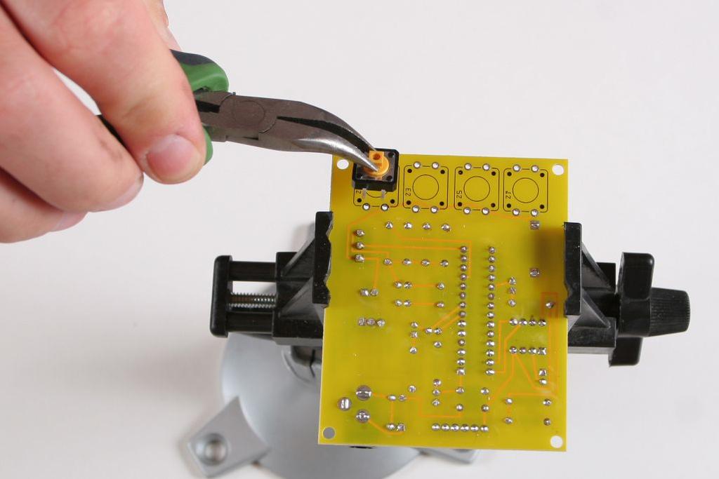
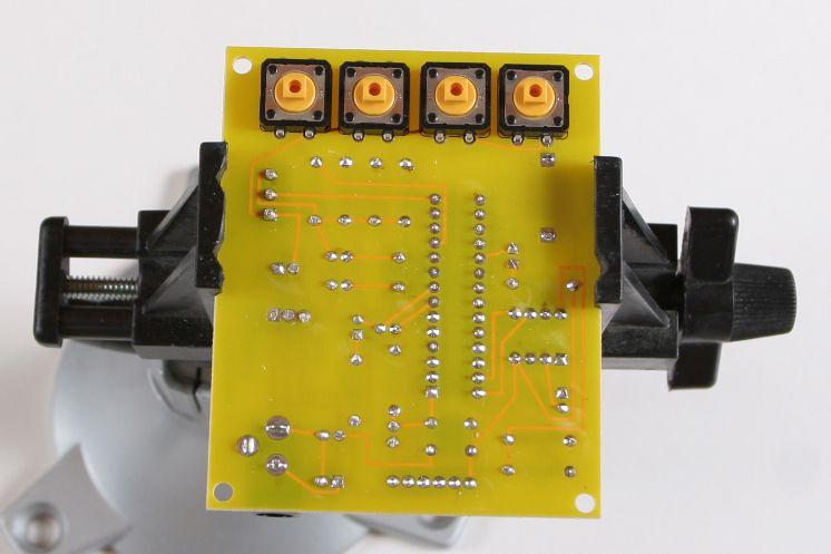
44

45 Solder Buttons caps Parts Quantity Image CAP TACTILE SQUARE RED 1 CAP TACTILE SQUARE WHITE 1 CAP TACTILE SQUARE GREEN 1 CAP TACTILE SQUARE BLACK 1


46 Place the button caps as displayed on the following picture. Some kits come with button caps with a pin in the center of the socket. You may have to cut it if the button in your kit don t have a center hole.

47 Coin Battery Insert the coin battery in the battery holder.
48

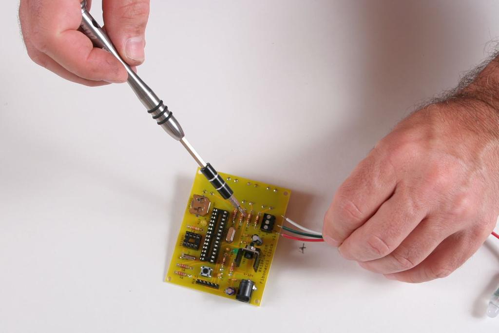
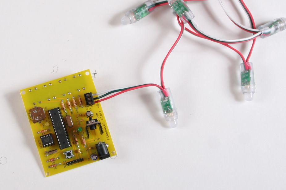
49 LED Pixels Separate the three wires of the LED strip. Strip the wires on approximately 5mm. Important note Some kits will ship with a slightly different LED strip. The center green wire being replaced by two transparent wires or by a blue wire. One of the transparent wires replaces the green wire while the other is connected with the white wire on the ground. You should use the transparent wire soldered to the center pin of the LED circuit board. If you are not sure what wire this is use a voltmeter to test connectivity between the transparent wires and the white wire. You should connect the one not connected to the ground (white). Other kits will ship with LED strips of different color. Red is the same but white is replaced by blue and the green center wire is replaced by white.
.")
50 An LED strip with two transparent wires. Uses the one connected to the center pin of the circuit board (IN). The other is connected to the ground with the white wire and can be ignored.

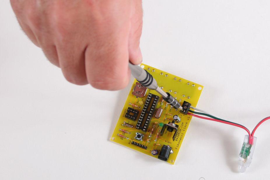
51 Screw the wires in the block terminal. Insert the red wire in the terminal marked with a (+) sign.
52

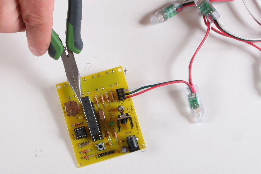
53 ICs Insert the DS1307 real time clock IC and the Atmega328P microcontroller in the two DIP sockets. Make sure the dents at the end of the ICs are aligned with their equivalent on the DIP socket.
54

55 Connect the 6V power to test the circuit.

56 You're done. Bravo! #
Ten Tec DDS Board Assembly Procedure
 05 May 2014 Ten Tec DDS Board Assembly Procedure You will find a photo of a completed board at the end of these instructions. Refer it whenever clarification is required. 1. AD9835 Attachment If you purchased
4ms SCM Breakout. Kit Builder's Guide for PCB v2.1 4mspedals.com
 4ms SCM Breakout Kit Builder's Guide for PCB v2.1 4mspedals.com Shuffling Clock Multiplier Breakout This guide is for building a Shuffling Clock Multiplier Breakout module (SCMBO) version 2.1 from the
Penrose Quantizer Assembly Guide
 Penrose Quantizer Assembly Guide Schematic and BOM The schematic can be found here: www.sonic-potions.com/public/penrosequantizerschematic.pdf The BOM is available at google docs: Link to BOM Prepare the
3. Assembly manual ANALYZING THE PCB'S LCD PCB. Component side: Solder side:
 3. Assembly manual ANALYZING THE PCB'S LCD PCB Component side: Solder side: MAIN PCB Component side: Solder side: ASSEMBLGING THE LCD PCB 1. Resistor R1: 33 Ohm (orange, black, black) 2. 6 Pin female header
Bill of Materials: Metronome Kit PART NO
 Metronome Kit PART NO. 2168325 The metronome kit allows you to build your own working electronic metronome. Features include a small speaker, flashing LED, and the ability to switch between several different
Warm Tube Clock. Before we start, please make sure that you have all required parts that come for the main board :
 Warm Tube Clock Assembly Instructions for the main board Introduction Congratulations on your purchase of OSH Nixie Tube Clock. In this document you will see all steps you need to follow in order to successfully
PS2-SMC-06 Servo Motor Controller Interface
 PS2-SMC-06 Servo Motor Controller Interface PS2-SMC-06 Full Board Version PS2 (Playstation 2 Controller/ Dual Shock 2) Servo Motor Controller handles 6 servos. Connect 1 to 6 Servos to Servo Ports and
16 Bit Micro Experimenter Assembly and Check out Instructions
 16 Bit Micro Experimenter Assembly and Check out Instructions The kit you purchased that includes PCB, schematic, complete parts list and these assembly instructions. A top picture of the complete assembly
Pacific Antenna Wall Wart Tamer 2.0 Kit
 Pacific Antenna Wall Wart Tamer 2.0 Kit Description The Wall Wart Tamer lets you utilize those surplus computer and wall pack power supplies as a clean, adjustable voltage, DC power source for radios and
ABC V1.0 ASSEMBLY IMPORTANT!
 ABC V1.0 ASSEMBLY Before starting this kit, prepare the following tools: Soldering iron (15-20W will do), flush cutters, no.2 hex screwdriver or allen key and phillips screwdriver. Also briefly go through
D.I.Y L.E.D CUBE 4X4X4. Level: Intermediate
 EN D.I.Y L.E.D CUBE 4X4X4 Level: Intermediate AK-125 TABLE OF CONTENTS Parts List... 2 Soldering Guide (Part A)... 3 Soldering Guide (Part B)... 5 Soldering Guide Without Recommend Products... 8 Appendix...
Assembly and User Guide
 Assembly and User Guide AtariPunkr is an adjustable stepped tone generator. AtariPunkr provides hours of fun everyone! Powered by: 9V Battery Outputs: Mylar Speaker (Included) Stereo Output (3.5mm Jack)
QUASAR PROJECT KIT # /24 HOUR GIANT CLOCK
 This project was originally published in the electronics magazine, Silicon Chip, a few years ago. It is issued here as a kit with permission. Some modifications to the original published circuit and software
Building The DC Beeper from Jackson Harbor Press A Morse code voltmeter / DC switch
 Building The DC Beeper and from Jackson Harbor Press Operating A Morse code voltmeter / DC switch The DC Beeper kit is a combination of a Morse code voltmeter with 20 mv resolution and a DC switch. The
Installation Manual of Talking Clock. 1. Install the 10KΩresistor (R18 R9 R10 R11 R12 R15 R14 R13) and 330Ω
 and 330Ω") Installation Manual of Talking Clock Photoresist Thermistor LED speaker NY3P065 STC15W408AS 10K 330 22p 22p Battery DS1302 Battery snap Crystal Oscillator 470uF DC Power Jack 1. Install the 10KΩresistor
Installation Manual of Talking Clock Photoresist Thermistor LED speaker NY3P065 STC15W408AS 10K 330 22p 22p Battery DS1302 Battery snap Crystal Oscillator 470uF DC Power Jack 1. Install the 10KΩresistor
Heartboard PCB Assembly Instructions
 Heartboard PCB Assembly Instructions Thanks for purchasing a Heartboard! These instructions will guide you through assembling and testing the Heartboard. Let s get started! Stuff you need Soldering iron
DRTXM2 TRANSMITTER BILL OF MATERIAL IDENT QTY PART NUMBER DESCRIPTION
 DRTXM2 TRANSMITTER BILL OF MATERIAL H1 C1-5,7,10-11,15,17-18,20, 22-28,34,38, 43-46,49-53,1A,2A 8 Right Angle LED Mount 0 0.01uf 50V Ceramic Disc Capacitor 31 0.1 UF/50V Decoupling Capacitors C13,14,39-42
MICROGRANNY v2.1 - Assembly Guide
 last update: 9. 5. 2017 MICROGRANNY v2.1 - Assembly Guide bastl-instruments.com INTRODUCTION Welcome to the assembly guide for the MicroGranny kit. MicroGranny is a monophonic granular sampler by Bastl
Bill of Materials: PWM Stepper Motor Driver PART NO
 PWM Stepper Motor Driver PART NO. 2183816 Control a stepper motor using this circuit and a servo PWM signal from an R/C controller, arduino, or microcontroller. Onboard circuitry limits winding current,
Foxhunt Offset Attenuator. Parts List:
 When your closing in on the fox you may find the signals to be so strong that you can no longer find a peak or null with your antenna. Sometimes the signal is so strong that the RF will leak straight into
Code Practice Oscillator (CPO) For kit building instructions turn to Page 3.
 For kit building instructions turn to Page 3.") Code Practice Oscillator (CPO) For kit building instructions turn to Page 3. Overview Many thanks for your purchase of this code practice oscillator or CPO, this guide is intended to allow you to quickly
Code Practice Oscillator (CPO) For kit building instructions turn to Page 3. Overview Many thanks for your purchase of this code practice oscillator or CPO, this guide is intended to allow you to quickly
DIY Function Generator XR2206
 DIY Function Generator XR2206 20Hz 100KHz http://radiohobbystore.com Components List: Resistors: R1, R2 1% Metal Film 5K1 R4 1% Metal Film 10K R5 1% Metal Film 3K R10 5% Carbon Film 10R R3, R9 Potentiometer
Assembly Instructions for the FRB FET FM 70 Watt Amp
 Assembly Instructions for the FRB FET FM 70 Watt Amp 1.) Orient the circuit board with the diagram 2.) Use a narrow chisel tip 25-30 watt soldering iron for assembly 3.) All the small parts are taped onto
Main improvements are increased number of LEDs and therefore better temperature indication with one Celsius degree increments.
 LED Thermometer V2 (Fahrenheit/Celsius/±1 ) PART NO. 2244754 After completing this great starter kit, users will have a nice interactive LED thermometer. You will learn one principle how temperature can
Build this Direct Digital Synthesizer "Development Kit" By: Diz Gentzow, W8DIZ
 Build this Direct Digital Synthesizer "Development Kit" By: Diz Gentzow, W8DIZ A great tutorial for adding a keypad to the DDS Kit by Bruce, W8BH This manual has been prepared to be read directly on screen.
Assembly Manual for VFO Board 2 August 2018
 Assembly Manual for VFO Board 2 August 2018 Parts list (Preliminary) Arduino 1 Arduino Pre-programmed 1 Faceplate Assorted Header Pins Full Board Rev A 10 104 capacitors 1 Rotary encode with switch 1 5-volt
IR add-on module circuit board assembly - Jeffrey La Favre January 27, 2015
 IR add-on module circuit board assembly - Jeffrey La Favre January 27, 2015 1 2 For the main circuits of the line following robot you soldered electronic components on a printed circuit board (PCB). The
Read This Page First
 Read This Page First If you are reading this you know the manuals are always available at QRPKITS.com. This is version 8.0 of the manual dated 4/27/2016. There is no need to print out the whole assembly
N3ZI Kits General Coverage Receiver, Assembly & Operations Manual (For Jun 2011 PCB ) Version 3.33, Jan 2012
 Version 3.33, Jan 2012") N3ZI Kits General Coverage Receiver, Assembly & Operations Manual (For Jun 2011 PCB ) Version 3.33, Jan 2012 Thank you for purchasing my general coverage receiver kit. You can use the photo above as a
N3ZI Kits General Coverage Receiver, Assembly & Operations Manual (For Jun 2011 PCB ) Version 3.33, Jan 2012 Thank you for purchasing my general coverage receiver kit. You can use the photo above as a
SSRP LTC1746 Assembly Manual V0.1 Check the most recent version
 SSRP LTC1746 Assembly Manual V0.1 Check the most recent version http://oscar.dcarr.org/ssrp/hardware/ltc1746/ltc1746.php Introduction This manual details the general assembly process for the SSRP LTC1746
LED Field Strength Indicator Kit
 LED Field Strength Indicator Kit Description The Field Strength Indicator kit from Qrpkits.com provides a visual way to monitor RF fields through the brightness of an LED. It will respond to RF fields
Digital Electronics & Chip Design
 Digital Electronics & Chip Design Lab Manual I: The Utility Board 1999 David Harris The objective of this lab is to assemble your utility board. This board, containing LED displays, switches, and a clock,
Building and Operating: Son of Zerobeat A PIC based CW zerobeat indicator from Jackson Harbor Press
 Building and Operating: Son of Zerobeat A PIC based CW zerobeat indicator from Jackson Harbor Press Ed Nisley, KE4ZNU, wrote an article published in the August, September and October of 1996 issues of
Build Your Own Clone Li l Reverb Kit Instructions
 Build Your Own Clone Li l Reverb Kit Instructions Warranty: BYOC, Inc. guarantees that your kit will be complete and that all parts and components will arrive as described, functioning and free of defect.
Assembly Instructions for the 1.5 Watt Amplifier Kit
 Assembly Instructions for the 1.5 Watt Amplifier Kit 1.) All of the small parts are attached to a sheet of paper indicating both their value and id. 2.) Leave the parts affixed to the paper until you are
LITTLE NERD v1.1 Assembly Guide
 last update: 9. 3. 2016 LITTLE NERD v1.1 Assembly Guide bastl instruments.com INTRODUCTION This guide is for building Little Nerd module from Bastl Instruments. It is good to have basic soldering skills
Designed to send specific MIDI information upon each press. Ultra-low current requirement means a single coin cell will last years
 PedalSync MIDI Data Module Key Features Discrete MIDI Data delivery in a compact design Designed to send specific MIDI information upon each press Ultra-low current requirement means a single coin cell
TS500 Assembly guide. Soldering. TS500 Assembly guide Main PCB 1. Diodes. Document revision 1.2 Last modification : 17/12/16
 TS500 Assembly guide Safety warning The kits are main powered and use potentially lethal voltages. Under no circumstance should someone undertake the realisation of a kit unless he has full knowledge about
Switcher Assembly guide. Switcher Assembly guide 1. Soldering. 2. Switcher3 vs Switcher2. 3. PCB split.
 Safety warning The kits are main powered and use potentially lethal voltages. Under no circumstance should someone undertake the realisation of a kit unless he has full knowledge about safely handling
LDB-1 Kit Instructions Page 1 of 8
 LDB-1 Kit Instructions Page 1 of 8 Important Information Congratulations and thank you for your purchase of the LDB-1 Little Drummer Boy Analog Drum Machine Kit! Before you start, please read the enclosed
Circuit Board Assembly Instructions for Babuinobot 1.0
 Circuit Board Assembly Instructions for Babuinobot 1.0 Brett Nelson January 2010 1 Features Sensor4 input Sensor3 input Sensor2 input 5v power bus Sensor1 input Do not exceed 5v Ground power bus Programming
Welcome! Welcome to the LVL1 TV-B-Gone workshop. We will be covering the following: How the TV-B-Gone works Basic soldering technique Component identi
 TV-B-Gone LVL1 Welcome! Welcome to the LVL1 TV-B-Gone workshop. We will be covering the following: How the TV-B-Gone works Basic soldering technique Component identification Construction of a Super TV-B-Gone
The µbotino Microcontroller Board
 The µbotino Microcontroller Board by Ro-Bot-X Designs Introduction. The µbotino Microcontroller Board is an Arduino compatible board for small robots. The 5x5cm (2x2 ) size and the built in 3 pin connectors
S&T GeoTronics LLC Open DSKY with AGC Assembly Instructions
 S&T GeoTronics LLC Open DSKY with AGC Assembly Instructions First, make sure you have all the required components: HARDWARE Qty Item 1 DSKY PCB v1.0d 1 Arduino Nano 1 VA RTC 1 IMU 1 Buck StepDown 1 SKM53
BMC029. Single Multiplier/Divider Last updated
 BMC029. Single Multiplier/Divider Last updated 1-4-2015 I Features -What it does/controls -Demos II Schematics -Pinout -Controls -Inputs -Output III Construction -Parts List -PCB information -How to Install
CV Arpeggiator Rev 1. Last updated
 CV Arpeggiator Rev Last updated 6--20 The CV Arpeggiator is a modular synth project used for creating arpeggios of control voltage. It utilizes a custom programmed PIC 6F685 micro controller. It includes
LA502 Assembly guide Main PCB Resistors - (2)
") LA502 Assembly guide Safety warning The kits are main powered and use potentially lethal voltages. Under no circumstance should someone undertake the realisation of a kit unless he has full knowledge about
LA502 Assembly guide Safety warning The kits are main powered and use potentially lethal voltages. Under no circumstance should someone undertake the realisation of a kit unless he has full knowledge about
Easy Transmitter. Support ETX_REV5_Manual V2.7 Revised
 Easy Transmitter Introduction The Easy Transmitter kit from qrpkits.com provides a basic, crystal controlled transmitter with VXO tuning to provide a small tuning range around the crystal frequency. It
ASSEMBLY MANUAL FOR R3500D DIRECTION FINDING RECEIVER KIT
 SDR-Kits www.sdr-kits.net SDR-Kits is CRKITS Authorised Distributor for Europe ASSEMBLY MANUAL FOR R3500D DIRECTION FINDING RECEIVER KIT Rev. A May 24, 2015 Written by CRKITS http://www.crkits.com Thanks
Line-Following Robot
 1 Line-Following Robot Printed Circuit Board Assembly Jeffrey La Favre October 5, 2014 After you have learned to solder, you are ready to start the assembly of your robot. The assembly will be divided
12V Dimmer Kit, version 2
 12V Dimmer Kit, version 2 User Manual Description The 12V Dimmer Kit V2 is an especially efficient PWM (pulse-width modulation) controller for 12V loads up to 60 watts. It features a single dial control
Construction Guide European Version
 Construction Guide European Version PCB This section describes how to build up the DRO-350 printed circuit board (PCB). The bare PCB is available for purchase on the order page. Static Protection Bare
PM124 Installation Instructions. See important note about revisions of this board on the last page.
 Marchand Electronics Inc. PO Box 473, Webster, NY 14580 Tel:(716) 872-0980 Fax:(716) 872-1960 info@marchandelec.com http://www.marchandelec.com (c)1997 Marchand Electronics Inc. PM124 Installation Instructions
Pacific Antenna Easy Transmitter Kit
 Pacific Antenna Easy Transmitter Kit Introduction The Easy Transmitter kit from qrpkits.com provides a crystal controlled transmitter with VXO tuning. The circuit consists of a N3904 based crystal oscillator
QRPme's Pocket PAL ][ version 2 Builder's Guide. December 11, 2017 by W1REX
![QRPme's Pocket PAL ][ version 2 Builder's Guide. December 11, 2017 by W1REX](/thumbs/85/92624497.jpg "QRPme's Pocket PAL ][ version 2 Builder's Guide. December 11, 2017 by W1REX") 1 QRPme's Pocket PAL ][ version 2 Builder's Guide December 11, 2017 by W1REX 2 Board, Parts & Tin Organized & Ready to build! You should sort and organize the parts for easy assembly later and to insure
1 QRPme's Pocket PAL ][ version 2 Builder's Guide December 11, 2017 by W1REX 2 Board, Parts & Tin Organized & Ready to build! You should sort and organize the parts for easy assembly later and to insure
Build Your Own Clone Mouse Kit Instructions
 Build Your Own Clone Mouse Kit Instructions Warranty: BYOC, Inc. guarantees that your kit will be complete and that all parts and components will arrive as described, functioning and free of defect. Soldering,
RadiØKit Μ CW HAM RADIO TRANSCEIVER KIT. Assembly and operating manual
 RadiØKit-120 20Μ CW HAM RADIO TRANSCEIVER KIT Assembly and operating manual Boreiou Ipirou 78 Kolonos Athens- Greece - 10444 Tel: 210.5150527 210.5132673 www.freebytes.com Thank you for buying RadiØKit-1,
Build Your Own Clone Li l Echo Kit Instructions
 Build Your Own Clone Li l Echo Kit Instructions Warranty: BYOC, Inc. guarantees that your kit will be complete and that all parts and components will arrive as described, functioning and free of defect.
Geiger Counter Kit Assembly Instructions ( )
") Geiger Counter Kit Assembly Instructions (2012-05-11) To build this kit, you should know how to solder. And it will be much easier if you have made other kits before. But even if this is your first kit,
Geiger Counter Kit Assembly Instructions (2012-05-11) To build this kit, you should know how to solder. And it will be much easier if you have made other kits before. But even if this is your first kit,
Amplifier, Product Design
 Amplifier, Product Design Choose one component from the amplifier circuit and investigate technical, theory and mathematical information related to your chosen component. This work will be completed over
How to build a Cracklebox. Red Wierenga Brooklyn College Center for Computer Music October 13, 2015
 How to build a Cracklebox Red Wierenga Brooklyn College Center for Computer Music October 13, 2015 What s a Cracklebox? What s a Cracklebox? The Cracklebox was developed by Michel Waisvisz and others at
555 Astable Kit MitchElectronics 2018
 555 Astable Kit MitchElectronics 2018 www.mitchelectronics.co.uk CONTENTS Introduction 3 Schematic 3 How It Works 4 Materials 6 Construction 7 Important Information 8 Page 2 INTRODUCTION The 555 timer
Pacific Antenna Field Strength Indicator Kit
 Pacific Antenna Field Strength Indicator Kit Description The Field Strength Indicator kit from Pacific Antenna provides a visual way to monitor the presence and relative strength RF fields through the
10 2 2,13,15,16,46 27, non-inductive ,26,
 HANDS-ON RADIO PARTS LIST (Thanks, John AF4WM and Steve AD7KR) Updated through Experiment 129 Quantities assume all parts available for re-use MAX QTY EXPERIMENT NOTES 1/4 WATT RESISTOR (All values are
LED Infinity Mirror Controller, 32 LEDs, Multiple Patterns.
 http://wwwinstructablescom/id/led-infinity-mirror-controller-32-leds-multiple-/ Food Living Outside Play Technology Workshop LED Infinity Mirror Controller, 32 LEDs, Multiple Patterns by ChromationSystems
The Guitar Chord Learning System
 The Guitar Chord Learning System Calvin A. Sessions Hardware Description April 19, 2005 Western Washington University Electronics Engineering Technology ETEC 474, Professor Morton INTRODUCTION The Guitar
Step by Step Building PJ meter ARDF Receiver Kit. CRKITS.COM August 5, 2013
 Step by Step Building PJ-80 80-meter ARDF Receiver Kit CRKITS.COM August 5, 2013 What is ARDF? ARDF is the abbreviation of Amateur Radio Direction Finding, or so called Fox Hunting. If you are looking
Build Your Own Clone 27V Boost Kit Instructions
 Build Your Own Clone 27V Boost Kit Instructions Warranty: BYOC, Inc. guarantees that your kit will be complete and that all parts and components will arrive as described, functioning and free of defect.
Lighthouse Beginner s soldering kit
 Lighthouse Beginner s soldering kit Kit contains: 1 x 220 ohm resistor (Red, Red, Black) 1 x 82k ohm resistor (Grey, Red, Orange) 2 x 220k ohm resistors (Red, Red, Yellow) 2 x Diodes 1 x Power switch 1
Build Your Own Clone Kuzco Jr. Kit Instructions
 Build Your Own Clone Kuzco Jr. Kit Instructions Warranty: BYOC, Inc. guarantees that your kit will be complete and that all parts and components will arrive as described, functioning and free of defect.
Custom Integrated Circuit (MSM9520RS) Replacement Module
 Replacement Module") FT-101Z/ FT-107/ FT-707/ FT-901,902 (later version) DISPLAY COUNTER UNIT (PB-2086A) Custom Integrated Circuit (MSM9520RS) Replacement Module Assembly and Installation Manual (v1.3e) STEP-BY-STEP PROCEDURES
FT-101Z/ FT-107/ FT-707/ FT-901,902 (later version) DISPLAY COUNTER UNIT (PB-2086A) Custom Integrated Circuit (MSM9520RS) Replacement Module Assembly and Installation Manual (v1.3e) STEP-BY-STEP PROCEDURES
BYOC Vibrato Kit Instructions BA6110 version
 BYOC Vibrato Kit Instructions BA6110 version Please read these instructions very thoroughly before building even if you are an experience builder. Because of the
ESE141 Circuit Board Instructions
 ESE141 Circuit Board Instructions Board Version 2.1 Fall 2006 Washington University Electrical Engineering Basics Because this class assumes no prior knowledge or skills in electrical engineering, electronics
DIODE / TRANSISTOR TESTER KIT
 DIODE / TRANSISTOR TESTER KIT MODEL DT-100K Assembly and Instruction Manual Elenco Electronics, Inc. Copyright 1988 Elenco Electronics, Inc. Revised 2002 REV-K 753110 DT-100 PARTS LIST If you are a student,
Building and Operating: LF Converter An SA612 based LF up-converter from Jackson Harbor Press
 Introduction: Building and Operating: LF Converter An SA612 based LF up-converter from Jackson Harbor Press The frequencies below the broadcast band are covered by few receivers on the market - those that
PM24 Installation Instructions
 Marchand Electronics Inc. PO Box 473, Webster, NY 14580 Tel:(716) 872-0980 Fax:(716) 872-1960 info@marchandelec.com http://www.marchandelec.com (c)1997 Marchand Electronics Inc. PM24 Installation Instructions
SoftRock v6.0 Builder s Notes. April 6, 2006
 SoftRock v6.0 Builder s Notes April 6, 006 Be sure to use a grounded tip soldering iron in building the v6.0 SoftRock circuit board. The soldering iron needs to have a small tip, (0.05-0. inch diameter),
BYOC Vibrato Kit Instructions BA662A version
 BYOC Vibrato Kit Instructions BA662A version Please read these instructions very thoroughly before building even if you are an experience builder. Because of the layout, there is a certain order which
CMU232 User Manual Last Revised October 21, 2002
 CMU232 User Manual Last Revised October 21, 2002 Overview CMU232 is a new low-cost, low-power serial smart switch for serial data communications. It is intended for use by hobbyists to control multiple
The Deluxe Tenna Dipper Design by: KD1JV Distributed by: Hendricks QRP kits,
 The Deluxe Tenna Dipper Design by: KD1JV Distributed by: Hendricks QRP kits, www.qrpkits.com The Tenna Dipper provides a simple means of determining the 50 ohm resonate frequency of an HF antenna or ATU
Multi-Window Comparator documentation. Written November 15, 2012 Last edited November 15, 2012
 Multi-Window Comparator documentation. Written November 15, 2012 Last edited November 15, 2012 I. What is a Multi-Window Comparator? A. A "regular" window comparator is this. B. A Multi-Window Comparator
SDR Cube Transceiver Online Assembly Guide
 SDR Cube Transceiver Online Assembly Guide Detailed construction notes for building and testing each of the SDR Cube kit modules Home Bill of Materials I/O Board Controls Board DSP Board Softrock SR-Base
AAØZZ Control Board for Si570 Daughtercard
 AAØZZ Control Board for Si570 Daughtercard Complete Signal Generator for 10 to 157 MHz By Craig Johnson, AAØZZ AAØZZ@CBJOHN.COM www.cbjohn.com/aaøzz TABLE OF CONTENTS 1 Introduction... 2 2 Hardware Description...
Ocean Controls KT-5198 Dual Bidirectional DC Motor Speed Controller
 Ocean Controls KT-5198 Dual Bidirectional DC Motor Speed Controller Microcontroller Based Controls 2 DC Motors 0-5V Analog, 1-2mS pulse or Serial Inputs for Motor Speed 10KHz, 1.25KHz or 156Hz selectable
QLG1 GPS Receiver kit
 QLG1 GPS Receiver kit 1. Introduction Thank you for purchasing the QRP Labs QLG1 GPS Receiver kit. This kit will provide a highly sensitive, highly accurate GPS receiver module, using the popular MediaTek
Build Your Own Clone Crown Jewel Kit Instructions
 Build Your Own Clone Crown Jewel Kit Instructions Warranty: BYOC, Inc. guarantees that your kit will be complete and that all parts and components will arrive as described, functioning and free of defect.
Electronic Components
 Electronic Components Arduino Uno Arduino Uno is a microcontroller (a simple computer), it has no way to interact. Building circuits and interface is necessary. Battery Snap Battery Snap is used to connect
GCI BRUTALIST JR. BUILD GUIDE
 GCI BRUTALIST JR. BUILD GUIDE The Brutalist Jr. is the DIY little brother to the GCI Brutalist, a high powered distortion pedal loosely based on the Providence Stampede SDT-1. It runs on 9v DC power or
Hendricks QRP Kits The Twofer Rev
 Hendricks QRP Kits The Twofer Rev 1 11-15-06 1. Description The Twofer is a classic QRP transmitter that s easy to assemble and operate. It uses a JFET VXO (variable crystal oscillator), driver stage and
DDS VFO 2 CONSTRUCTION MANUAL. DDS VFO 2 Construction Manual Issue 1 Page 1
 DDS VFO 2 CONSTRUCTION MANUAL DDS VFO 2 Construction Manual Issue 1 Page 1 Important Please read before starting assembly STATIC PRECAUTION The DDS VFO kit contains the following components which can be
HT-1A Dual Band CW QRP Transceiver. Kit Building Instructions
 HT-A Dual Band CW QRP Transceiver Kit Building Instructions Rev B, July 8, 08 Designed by BD4RG Exclusively distributed by CRKITS.COM and its worldwide distributors Join the group http://groups.io/g/crkits
Ocean Controls KT-5221 Modbus IO Module
 Ocean Controls Modbus IO Module 8 Relay Outputs 4 Opto-Isolated Inputs 2 Analog Inputs (10 bit) 1 PWM Output (10 bit) 4 Input Counters Connections via Pluggable Screw Terminals 0-5V or 0-20mA Analog Inputs,
Quick Response Alarm. Version Printings
 Quick Response Alarm Version 1.00 Printings Version 1.00: 01/07/2005 TABLE OF CONTENTS SPECIFICATIONS... 1 1.0 GENERAL DESCRIPTION... 2 1.1 Description... 2 1.2 Capabilities and Features... 2 1.3 Operation...
DIY KIT 141. Multi-Mode Timer
 INTRODUCTION No one can call themselves an electronics hobbyist unless they have built a timer. There are many tens of designs using a variety of new and sometimes old circuits. Witness the longest surviving
Mono Amplifier. LM386 Headphone Amp
 Mono Amplifier LM386 Headphone Amp Layout On/Off Switch - cuts power to the circuit Mono Input Jack: use either L or R or solder together Schematic Step 1 - Parts List 1.) R1-10ohm Resistor - Brown Black
8x8 Red Blue Green Yellow Audio Indicator
 8x8 Red Blue Green Yellow Audio Indicator 1. Introduce. 1>. Working voltage: 5V. 2>. PCB size: 75*45mm. 3>. There are four fixed mounting holes on PCB. 4>. It is no need for filter circuit. It can driver
Patton Robotics, LLC.
 Patton Robotics LLC Patton Robotics T3 Motherboard Assembly Instructions Version 1.1 Patton Robotics, LLC. 61 Hagan Drive New Hope, PA 18938 Phone: 609-977-5525 Email: pattonrobotics@gmail.com Copyright
Dirtbaby FX TYPE: Delay Based on the EHX DMM 2016 madbeanpedals
 Dirtbaby FX TYPE: Delay Based on the EHX DMM 2016 madbeanpedals 3.325 W x 2.325 H Terms of Use: You are free to use purchased circuit boards for both DIY and small commercial operations. You may not offer
Because FRONTBOX2 is a kit, the assembly work is necessary. ANALOGDISCOVERY2 is not included in FRONTBOX2.
 1. Outline FRONTBOX2 makes ANALOGDISCOVERY2 the same easiness as a general measuring instrument. FRONTBOX2 is used with ANALOGDISCOVERY2. ANALOGDISCOVERY2 and The PC environment for ANALOGDISCOVERY2 is
FM Audio/Squelch Board by Steve Dold, W6KCS w6kcs (at) stevedold (dot) com
 stevedold (dot) com") FM Audio/Squelch Board by Steve Dold, W6KCS w6kcs at stevedold dot com Board hardware version 7-8 Firmware version 7.x This board connects to an FM receiver's discriminator/detector and provides squelched,
FM Audio/Squelch Board by Steve Dold, W6KCS w6kcs at stevedold dot com Board hardware version 7-8 Firmware version 7.x This board connects to an FM receiver's discriminator/detector and provides squelched,