TekBot Remote Control Receiver Board Construction
|
|
|
- Linette Rhoda Thomas
- 5 years ago
- Views:
Transcription
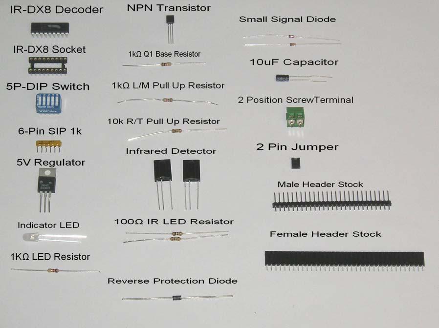
1 TekBot Remote Control Receiver Board Construction Purpose This tutorial illustrates the procedure for construction of the Receiver board for the TekBot. A Guide to Soldering Many of you have soldered once or twice before but most likely very few of you have ever been instructed how to recognize good soldering from bad soldering. There are a few basic concepts involved in soldering that we will detail here, the first being that solder itself melts with heat. Well duh. Part of this simple concept though is the key to making a good solder joint. A good solder joint will conduct electricity well and prevent the component from falling out. Since solder melts with heat we need to be sure that we give enough heat to the solder to get it to melt uniformly, not in clumps. A solder joint that was made without enough heat is called a cold joint (See the figure below). Another problem can be if there is too much or too little solder used for the joint. If too little solder is used the joint will not be strong enough and will likely break. If too much is used there is a risk of a solder bridge being formed (See figures below). An ideal joint should appear shiny even after it cools and should look like the solder is stretched from the pad to the wire. Pre-Project Look over the parts list & circuit board and become familiar with the placement of all the components. Be sure to pay special attention to diodes and capacitors that have polarity markings. (Components that can only go in one way) Note that the foot prints show in Fig. 1 will NOT be connected. These are for RF components that will not be part of this lab. Fig. 2 Shows all the components laid out in the order of the parts lists. We will be placing them in a different order. You may want to print out the parts list or use two monitors if possible. 1

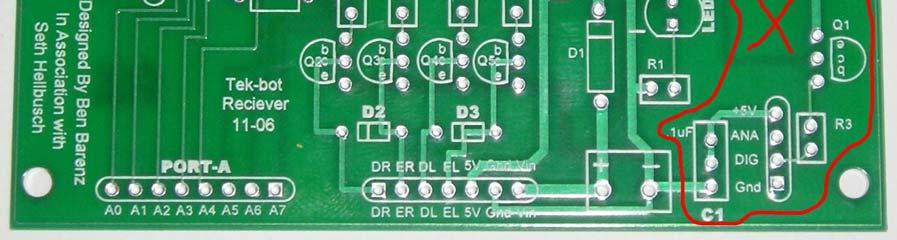
2 FIG 1 FIG 2 2
3 Receiver Board Parts list Part Description Circuit ID Quantity 18-Pin IC Socket DIP-18 Decoder for IC-1 Socket IC-1 1 Decoder DIP-18 IC IR-DX8 1 5P-DIP Switch DIP-10 Blue Switch Dip Switch 1 6-Pin SIP 1k Yellow SIP Resistor SIP-1 1 5V Regulator Big 3 Pin IC VR-1 1 Indicator LED Translucent lens LED 1 1KΩ LED Resistor brown,black,red R1 1 NPN Transistor Small 3 pin IC Q2-Q5 4 1kΩ Q1 Base Resistor brown,black,red R8-R11 4 1kΩ L/M Pull Up Resistor brown,black,red R4 1 10k R/T Pull Up Resistor brown, black,orange R5 1 Infrared Detector IR Detector IRDetector 2 100Ω IR LED Resistor brown,black,brown R6,R7 2 Reverse Protection Diode Black with Grey stripe D1 1 Small Signal Diode Small Glass Diode D2,D3 2 10uF Capacitor Small Black round Cap C2 1 2 Position Screw Terminal Green Screw Terminal T Pin Jumper small 2pin black J1,J2.J3 3 3 Pin Male Header black (pins) J2 1 2 Pin Male Header Black (pins) J3 1 7 Pin Female Header Power DR,ER,DL,EL,5V,GN D power 1 8 Pin Female Header Port-A Black (holes) Port-A 8 Total 29 Look over this parts list and the photo and make sure you have all your components. If you have a missing or damaged component alert one of the lab technicians before proceeding. Tools: Soldering Iron Flux Core Solder Wire cutters Small Pliers (Optional) 3


4 Assembly The first components we will place are the DIP-18 Socket, 6-Pin SIP resistor and the 5P DIP Switch as shown in Fig 3. FIG 3 Start by placing the DIP-18 IC socket. The notch goes UP as shown in Fig 3. Flip the board over, then while holding the component from the back side solder the first pin in the upper corner. Apply solder then hold the iron tip on the joint for about 1 second then remove. Repeat this process for the rest of the pins as shown in Fig 4. 4


5 FIG 4 Next, place the SIP resistor with the black dot facing down on the board as shown in Fig 5. Then solder in the 5P DIP Switch in Fig 5. FIG 5 5

6 Next we will place the 5V regulator and 2-Pin Screw terminal. Start by bending the leads of the regulator as shown in Fig 6a, 6b. Next place the regulator in the spot marked on the silk screen then solder. Then place the screw terminal in as shown in Fig 6c and solder. FIG 6 Next we will be placing the diodes. Pay special attention to the polarity marked by the line on one end of the diode. Place the reverse protection diode, small signal diodes, and indicator LED as shown in Fig 7. 6


7 FIG 7 Next we will be placing the Resistors. We need six 1kΩ resistors for R1,R4,R8,R9,R10,R11 two 100Ω resistors for R6,R7 and one 10kΩ resistor for R5. All of the resistors will be vertical mount as shown in Fig 8. FIG 8 7


8 Next we will place the four NPN Transistors and the 10μF Capacitor as shown in Fig 9a. Pay careful attention to the orientation of the transistors outlined in the silk screen. When placing the capacitor, the white stripe on the side goes on the negative side as shown in Fig 9b. FIG 9 Next we need to cut our headers. We need one 2-Pin male header, one 3-Pin male header, one 8-Pin female header, one 7-Pin female header and two 4-pin female headers as shown in Fig 10a. Cut the headers from the stock pieces and solder in place as shown in Fig 10b. The two 4-pin females can be made out of standard female header or the SIP socket style shown. The SIP socket style holds the part better and since these will hold the IR Detectors we want them to be secure. FIG 10 8


9 We are now done soldering! Next, place the IR-DX8 into the DIP-18 socket. Place a 2- pin jumper across J2 and J3 as shown in Fig 11. Finally insert the IR detectors as shown in Fig 11. FIG 11 Next we will install the receiver board on the TekBot. 9


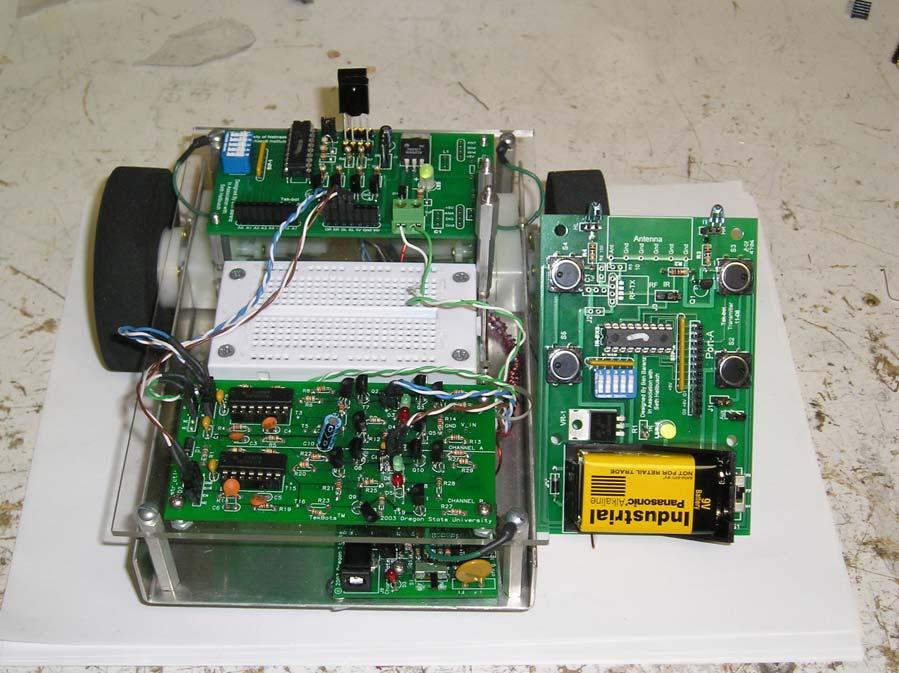
10 Installing Receiver board on TekBbot First install the receiver board as shown in Fig 12. FIG 12 Next we will need two 2-Pin wires to connect the motor controller board to the receiver board and one 2-Pin wire for power. Cut three sets of two wires approximately 8 long. Then solder a 2-pin male header to the end of each wire as shown in Fig 13. On one wire used for power DO NOT solder header pins to one end of the wires because these will be connected to the screw terminals. 10

11 FIG 13 The final step is to connect the wires to the TekBot. Connect the DR ER to the Direction and Enable pin for the Right motor and DL EL for the left motor respectively. Connect the header end of the power wire to a free port on the charger board and using a small flat screw driver, tighten the wires down into the screw terminal. You may connect the polarity backwards and observer the reverse hook up protection feature of the receiver board. Finally turn on the power and your ready to drive! Try changing the address on the transmitter and receiver using the DIP switches. If others units are in the room you will have to have a different address or your TekBots will interfere with each other. There are 32 different channels available for the TekBot. 11
12 12
Tek-Bot Remote Control Transmitter Board Construction
 Tek-Bot Remote Control Transmitter Board Construction Purpose This tutorial illustrates the procedure for construction of the Transmitter board for the Tek-bot. A Guide to Soldering Many of you have soldered
Circuit Board Assembly Instructions for Babuinobot 1.0
 Circuit Board Assembly Instructions for Babuinobot 1.0 Brett Nelson January 2010 1 Features Sensor4 input Sensor3 input Sensor2 input 5v power bus Sensor1 input Do not exceed 5v Ground power bus Programming
Electronics Merit Badge Class 4. 12/30/2010 Electronics Merit Badge Class 4 1
 Electronics Merit Badge Class 4 12/30/2010 Electronics Merit Badge Class 4 1 Soldering Safety Note: A Soldering Iron gets hotter than 374 F. Do not touch the soldering iron s metal parts or you will receive
Instructions for Building the Pulsed Width Modulation Circuit. MC-12 (DC Motor Controller or PWM) From Electronic Light Inc.
 From Electronic Light Inc.") Instructions for Building the Pulsed Width Modulation Circuit MC-2 (DC Motor Controller or PWM) From Electronic Light Inc. (revised 3/08) Using this circuit for a pulsed DC current to your cell, Do NOT
Instructions for Building the Pulsed Width Modulation Circuit MC-2 (DC Motor Controller or PWM) From Electronic Light Inc. (revised 3/08) Using this circuit for a pulsed DC current to your cell, Do NOT
Patton Robotics, LLC.
 Patton Robotics LLC Patton Robotics T3 Motherboard Assembly Instructions Version 1.1 Patton Robotics, LLC. 61 Hagan Drive New Hope, PA 18938 Phone: 609-977-5525 Email: pattonrobotics@gmail.com Copyright
Ten Tec DDS Board Assembly Procedure
 05 May 2014 Ten Tec DDS Board Assembly Procedure You will find a photo of a completed board at the end of these instructions. Refer it whenever clarification is required. 1. AD9835 Attachment If you purchased
4ms SCM Breakout. Kit Builder's Guide for PCB v2.1 4mspedals.com
 4ms SCM Breakout Kit Builder's Guide for PCB v2.1 4mspedals.com Shuffling Clock Multiplier Breakout This guide is for building a Shuffling Clock Multiplier Breakout module (SCMBO) version 2.1 from the
LITTLE NERD v1.1 Assembly Guide
 last update: 9. 3. 2016 LITTLE NERD v1.1 Assembly Guide bastl instruments.com INTRODUCTION This guide is for building Little Nerd module from Bastl Instruments. It is good to have basic soldering skills
Bill of Materials: PWM Stepper Motor Driver PART NO
 PWM Stepper Motor Driver PART NO. 2183816 Control a stepper motor using this circuit and a servo PWM signal from an R/C controller, arduino, or microcontroller. Onboard circuitry limits winding current,
KK1L Icom Band Decoder Basic Assembly
 KK1L Icom Band Decoder Basic Assembly Ronald Rossi, KK1L http://home.comcast.net/~kk1l Features: RFI isolated inputs Fully opto-isolated Replaces one BCD band decode port on KK1L dual decoder Description:
IR add-on module circuit board assembly - Jeffrey La Favre January 27, 2015
 IR add-on module circuit board assembly - Jeffrey La Favre January 27, 2015 1 2 For the main circuits of the line following robot you soldered electronic components on a printed circuit board (PCB). The
Pingable Envelope Generator
 Pingable Envelope Generator Kit Builder's Guide for PCB v1.0.3 4mspedals.com PEG This guide is for building a Pingable Envelope Generator (PEG), which is an intermediate-level kit. You should be confident
Pacific Antenna - Easy TR Switch
 Pacific Antenna - Easy TR Switch Kit Description The Easy TR Switch is an RF sensing switch that can be used to switch an antenna between a receiver and transmitter. It also has a second switched pair
VC Divider Assembly manual
 1 VC Divider Assembly manual Thank you for your purchase of the SSSR Labs VC Divider DIY Kit! This manual will help you assemble the VC Divider quickly and easily. Follow the instructions! As you may know,
3. Assembly manual ANALYZING THE PCB'S LCD PCB. Component side: Solder side:
 3. Assembly manual ANALYZING THE PCB'S LCD PCB Component side: Solder side: MAIN PCB Component side: Solder side: ASSEMBLGING THE LCD PCB 1. Resistor R1: 33 Ohm (orange, black, black) 2. 6 Pin female header
Pacific Antenna Easy TR Switch
 Pacific Antenna Easy TR Switch Kit Description The Easy TR Switch is an RF sensing circuit with a double pole double throw relay that can be used to automatically switch an antenna between a separate receiver
Assembly instructions for the CS-1 ChemShield
 Page 1 Of 6 Assembly instructions for the CS-1 ChemShield What is S.M.D SMD=Surface mount devices, like all the components does not have leads, but gets soldered onto flat solder pads. The CS-1 assembly
Line Following Circuit Board Wiring Guide
 Line Following Circuit Board Wiring Guide Soldering the Analog Optosensors 1. Obtain a line following printed circuit board from the store as well as three analog optosensors (w/6 resistors). 2. Remove
TV Remote. Discover Engineering. Youth Handouts
 Discover Engineering Youth Handouts Electronic Component Guide Component Symbol Notes Amplifier chip 1 8 2 7 3 6 4 5 Capacitor LED The amplifier chip (labeled LM 386) has 8 legs, or pins. Each pin connects
LED Field Strength Indicator Kit
 LED Field Strength Indicator Kit Description The Field Strength Indicator kit from Qrpkits.com provides a visual way to monitor RF fields through the brightness of an LED. It will respond to RF fields
DIODE / TRANSISTOR TESTER KIT
 DIODE / TRANSISTOR TESTER KIT MODEL DT-100K 99 Washington Street Melrose, MA 02176 Phone 781-665-1400 Toll Free 1-800-517-8431 Visit us at www.testequipmentdepot.com Assembly and Instruction Manual Elenco
LDB-1 Kit Instructions Page 1 of 8
 LDB-1 Kit Instructions Page 1 of 8 Important Information Congratulations and thank you for your purchase of the LDB-1 Little Drummer Boy Analog Drum Machine Kit! Before you start, please read the enclosed
12V Dimmer Kit, version 2
 12V Dimmer Kit, version 2 User Manual Description The 12V Dimmer Kit V2 is an especially efficient PWM (pulse-width modulation) controller for 12V loads up to 60 watts. It features a single dial control
Bill of Materials: Metronome Kit PART NO
 Metronome Kit PART NO. 2168325 The metronome kit allows you to build your own working electronic metronome. Features include a small speaker, flashing LED, and the ability to switch between several different
Build this Direct Digital Synthesizer "Development Kit" By: Diz Gentzow, W8DIZ
 Build this Direct Digital Synthesizer "Development Kit" By: Diz Gentzow, W8DIZ A great tutorial for adding a keypad to the DDS Kit by Bruce, W8BH This manual has been prepared to be read directly on screen.
Instructions for Building the Pulsed Width Modulation Circuit. MC-12 (DC Motor Controller or PWM) From Electronic Light Inc. (revised kit 5/08)
 From Electronic Light Inc. (revised kit 5/08)") Instructions for Building the Pulsed Width Modulation Circuit MC-12 (DC Motor Controller or PWM) From Electronic Light Inc. (revised kit 5/08) Using this circuit for a pulsed DC current to your cell. Do
Instructions for Building the Pulsed Width Modulation Circuit MC-12 (DC Motor Controller or PWM) From Electronic Light Inc. (revised kit 5/08) Using this circuit for a pulsed DC current to your cell. Do
Pacific Antenna Field Strength Indicator Kit
 Pacific Antenna Field Strength Indicator Kit Description The Field Strength Indicator kit from Pacific Antenna provides a visual way to monitor the presence and relative strength RF fields through the
D.I.Y L.E.D CUBE 4X4X4. Level: Intermediate
 EN D.I.Y L.E.D CUBE 4X4X4 Level: Intermediate AK-125 TABLE OF CONTENTS Parts List... 2 Soldering Guide (Part A)... 3 Soldering Guide (Part B)... 5 Soldering Guide Without Recommend Products... 8 Appendix...
Instructions for Building the Pulsed Width Modulation Circuit. MC-12 (DC Motor Controller or PWM) From Electronic Light Inc. (revised kit 8/08)
 From Electronic Light Inc. (revised kit 8/08)") Instructions for Building the Pulsed Width Modulation Circuit MC-12 (DC Motor Controller or PWM) From Electronic Light Inc. (revised kit 8/08) Using this circuit for a pulsed DC current to your cell. Do
Instructions for Building the Pulsed Width Modulation Circuit MC-12 (DC Motor Controller or PWM) From Electronic Light Inc. (revised kit 8/08) Using this circuit for a pulsed DC current to your cell. Do
Assembly Instructions for B7971 Smart Socket
 Assembly Instructions for B7971 Smart Socket Identification and installation of the resistors, Fig1 Segment 1,R1, 22k Segment 4, R4, 22k Segment 2, R2, 27k Segment 3, R3, 27k Segment 5, R5, 27k Segment
Assembly Instructions
 Assembly Instructions For the SSQ-2F 3.1 MHz Rife Controller Board Kit v1.41 Manual v1.00 2012 by Ralph Hartwell Spectrotek Services GENERAL ASSEMBLY INSTRUCTIONS Arrange for a clean work surface with
TS500 Assembly guide. Soldering. TS500 Assembly guide Main PCB 1. Diodes. Document revision 1.2 Last modification : 17/12/16
 TS500 Assembly guide Safety warning The kits are main powered and use potentially lethal voltages. Under no circumstance should someone undertake the realisation of a kit unless he has full knowledge about
RC Interface Controller Board Assembly and Operation
 RC Interface Controller Board Assembly and Operation Revision Date: January 17, 2006 SUPERDROIDROBOTS.COM RC Interface Controller Board Accurate content is of the utmost importance to the authors of this
DuoDrive Nixie Bargraph Kit
 Assembly Instructions And User Guide Nixie Bargraph Kit - 1 - REVISION HISTORY Issue Date Reason for Issue Number 1 12 December 2017 New document - 2 - 1. INTRODUCTION 1.1 About Nixie Bargraph Driver IN-9
OpenROV. Guide 3 - Electronics. We will now move to the assembly of the electronics that will control the ROV. Written By: OpenROV
 OpenROV Guide 3 - Electronics We will now move to the assembly of the electronics that will control the ROV. Written By: OpenROV 2017 openrov.dozuki.com Page 1 of 33 INTRODUCTION We will introduce soldering
Pacific Antenna Code Practice Oscillator Kit
 Pacific Antenna Code Practice Oscillator Kit This kit is offered to initiate the first time builder in the various techniques of mechanical and electronic kit construction. At the end of the approximately
Switcher Assembly guide. Switcher Assembly guide 1. Soldering. 2. Switcher3 vs Switcher2. 3. PCB split.
 Safety warning The kits are main powered and use potentially lethal voltages. Under no circumstance should someone undertake the realisation of a kit unless he has full knowledge about safely handling
Figure 1. CheapBot Smart Proximity Detector
 The CheapBot Smart Proximity Detector is a plug-in single-board sensor for almost any programmable robotic brain. With it, robots can detect the presence of a wall extending across the robot s path or
Rob G, 10W LED Ren48LSD compatible LED Driver: Parts List: 1 x 10W RGB LED Driver PCB. 1 x.1uf capacitor(c2)
") Rob G, 10W LED Ren48LSD compatible LED Driver: Parts List: 1 x 10W RGB LED Driver PCB 1 x.1uf capacitor(c2) 3 x 0.33 resistors (R1, R2, R3) 3 x 4k7 resistors (R4, R5, R6) 3 x 1N5819 Diode (Diode must be
Rob G, 10W LED Ren48LSD compatible LED Driver: Parts List: 1 x 10W RGB LED Driver PCB 1 x.1uf capacitor(c2) 3 x 0.33 resistors (R1, R2, R3) 3 x 4k7 resistors (R4, R5, R6) 3 x 1N5819 Diode (Diode must be
Solder Practice Kit MODEL AK-100. Elenco Electronics, Inc. Lesson Manual. Elenco Electronics, Inc.
 Solder Practice Kit MODEL AK-100 Elenco Electronics, Inc. 150 W. Carpenter Avenue Wheeling, IL 60090 (847) 541-3800 http://www.elenco.com e-mail: elenco@elenco.com Lesson Manual Elenco Electronics, Inc.
LA502 Assembly guide Main PCB Resistors - (2)
") LA502 Assembly guide Safety warning The kits are main powered and use potentially lethal voltages. Under no circumstance should someone undertake the realisation of a kit unless he has full knowledge about
LA502 Assembly guide Safety warning The kits are main powered and use potentially lethal voltages. Under no circumstance should someone undertake the realisation of a kit unless he has full knowledge about
Read This Page First
 Read This Page First If you are reading this you know the manuals are always available at QRPKITS.com. This is version 8.0 of the manual dated 4/27/2016. There is no need to print out the whole assembly
SPACE WAR GUN KIT MODEL K-10. Assembly and Instruction Manual. Elenco Electronics, Inc.
 SPACE WAR GUN KIT MODEL K-10 Assembly and Instruction Manual Elenco Electronics, Inc. Copyright 1989 Elenco Electronics, Inc. Revised 2001 REV-H 753210A PARTS LIST Contact Elenco Electronics (address/phone/e-mail
Any Questions? Contact us or Alligator Blinkie
 Alligator Blinkie The heart of this blinkie is a 12F1822 PIC produced by a company called Microchip. A PIC is a tiny, yet surprisingly powerful little computer. By itself, it can t do much it needs someway
Instructions for Building the Pulsed Width Modulation Circuit. MC-12 (DC Motor Controller or PWM) From Electronic Light Inc. (revised kit 10/03/08)
 From Electronic Light Inc. (revised kit 10/03/08)") Instructions for Building the Pulsed Width Modulation Circuit MC-12 (DC Motor Controller or PWM) From Electronic Light Inc. (revised kit 10/03/08) Congratulations on your purchase of the MC-12 DC Motor
Instructions for Building the Pulsed Width Modulation Circuit MC-12 (DC Motor Controller or PWM) From Electronic Light Inc. (revised kit 10/03/08) Congratulations on your purchase of the MC-12 DC Motor
5W Mono Amplifier Kit
 5W Mono Amplifier Kit Kit Construction Before you start assembling your kit there are a couple of important things you must do. FIRST read through these instructions entirely before you start construction
DIODE / TRANSISTOR TESTER KIT
 DIODE / TRANSISTOR TESTER KIT MODEL DT-100K Assembly and Instruction Manual Elenco Electronics, Inc. Copyright 1988 Elenco Electronics, Inc. Revised 2002 REV-K 753110 DT-100 PARTS LIST If you are a student,
ABC V1.0 ASSEMBLY IMPORTANT!
 ABC V1.0 ASSEMBLY Before starting this kit, prepare the following tools: Soldering iron (15-20W will do), flush cutters, no.2 hex screwdriver or allen key and phillips screwdriver. Also briefly go through
FROM SCHEMATIC TO VEROBOARD
 FROM SCHEMATIC TO VEROBOARD The circuit of a bench amplifier utilising a LM386 linear (integrated circuit) IC and a few other components is used for this tutorial. The schematic is shown below: First a
Project 747 VERSION 1.3 USER MANUAL February 22nd 2018
 VERSION 1.3 USER MANUAL February 22nd 2018 WWW.GARAGE1217.COM WARNING: Project requires knowledge of AC electrical systems, repair of said systems and restoration of said systems. If proper safety measures
Assembly Instructions for the 1.5 Watt Amplifier Kit
 Assembly Instructions for the 1.5 Watt Amplifier Kit 1.) All of the small parts are attached to a sheet of paper indicating both their value and id. 2.) Leave the parts affixed to the paper until you are
Lightning Detector 1.0
 Lightning Detector 1.0 Instruction Manual Eastern Voltage Research, LLC January 2017, REV A 1 http://www.easternvoltageresearch.com SAFETY DISCLAIMER THIS KIT IS FOR HOBBY / NOVELTY USE ONLY. IT IS NOT
SUPER Tuna ][+ Builder s Guide
![SUPER Tuna ][+ Builder s Guide](/thumbs/72/66369453.jpg "SUPER Tuna ][+ Builder s Guide") SUPER Tuna ][+ Builder s Guide Ver2.3 Rex Harper W1REX 3/25/2015 The first thing you should do is to familiarize yourself with what you are going to build. The previous 3 pages are schematics of the
SUPER Tuna ][+ Builder s Guide Ver2.3 Rex Harper W1REX 3/25/2015 The first thing you should do is to familiarize yourself with what you are going to build. The previous 3 pages are schematics of the
Easy Transmitter. Support ETX_REV5_Manual V2.7 Revised
 Easy Transmitter Introduction The Easy Transmitter kit from qrpkits.com provides a basic, crystal controlled transmitter with VXO tuning to provide a small tuning range around the crystal frequency. It
Penrose Quantizer Assembly Guide
 Penrose Quantizer Assembly Guide Schematic and BOM The schematic can be found here: www.sonic-potions.com/public/penrosequantizerschematic.pdf The BOM is available at google docs: Link to BOM Prepare the
Construction Guide European Version
 Construction Guide European Version PCB This section describes how to build up the DRO-350 printed circuit board (PCB). The bare PCB is available for purchase on the order page. Static Protection Bare
Value Location Qty Potentiometers C1M Distortion 1 A10k Volume 1. Footswitch 3PDT SW1 1. Jacks 1/4 Mono 2 DC Power 1
 Distortion BUILD INSTRUCTIONS Thank you for your purchase of our Distortion+ kit! We have completely redesigned our entire line of kits to be the most user friendly, while still maintaining their same
Congratulations on your purchase of the SparkFun Arduino ProtoShield Kit!
 Congratulations on your purchase of the SparkFun Arduino ProtoShield Kit! Well, now what? The focus of this guide is to aid you in turning that box of parts in front of you into a fully functional prototyping
MICROGRANNY v2.1 - Assembly Guide
 last update: 9. 5. 2017 MICROGRANNY v2.1 - Assembly Guide bastl-instruments.com INTRODUCTION Welcome to the assembly guide for the MicroGranny kit. MicroGranny is a monophonic granular sampler by Bastl
HT-1A Dual Band CW QRP Transceiver. Kit Building Instructions
 HT-A Dual Band CW QRP Transceiver Kit Building Instructions Rev B, July 8, 08 Designed by BD4RG Exclusively distributed by CRKITS.COM and its worldwide distributors Join the group http://groups.io/g/crkits
Xkitz.com XLO-5CP Control Panel for Five Channel Color Light Organ
 Xkitz.com XLO-5CP Control Panel for Five Channel Color Light Organ Rev 1.15 An Optional accessory for the Xkitz XLO-5 or XLO-5DC 5 Channel Color Light Organs Introduction This kit contains all the electronics
Guitarpedalkits.com Overdrive Pedal Build Instructions
 Page 1 Guitarpedalkits.com Overdrive Pedal Build Instructions Follow the instructions in this guide to build your very own DIY overdrive pedal from GuitarPedalKits.com. If you re a first time builder,
Gat ew ay T o S pace AS EN / AS TR Class # 07. Colorado S pace Grant Consortium
 Gat ew ay T o S pace AS EN / AS TR 2500 Class # 07 Colorado S pace Grant Consortium One Minute Reports: - Can we have two data loggers? - Do you provide us with cameras? {Hardware Checkout after proposal}
SSRP LTC1746 Assembly Manual V0.1 Check the most recent version
 SSRP LTC1746 Assembly Manual V0.1 Check the most recent version http://oscar.dcarr.org/ssrp/hardware/ltc1746/ltc1746.php Introduction This manual details the general assembly process for the SSRP LTC1746
Read This Page First
 Read This Page First If you are reading this you know the manuals are always available at QRPKITS.com. If you have questions contact qrpkits.com@gmail.com There is no need to print out the whole assembly
QRPGuys Michigan Mighty Might Plus 40M Transmitter
 QRPGuys Michigan Mighty Might Plus 40M Transmitter First, familiarize yourself with the parts and check for all the components. If a part is missing, please contact us and we will send one. You must use
16 Bit Micro Experimenter Assembly and Check out Instructions
 16 Bit Micro Experimenter Assembly and Check out Instructions The kit you purchased that includes PCB, schematic, complete parts list and these assembly instructions. A top picture of the complete assembly
Building the Toothpick Audio CW Filter
 Building the Toothpick Audio CW Filter Introduction The toothpick is a simple variable bandpass audio filter designed to compliment the Splinter QRPp Trans-Receiver. The filter also contains an audio amplifier
Warm Tube Clock. Before we start, please make sure that you have all required parts that come for the main board :
 Warm Tube Clock Assembly Instructions for the main board Introduction Congratulations on your purchase of OSH Nixie Tube Clock. In this document you will see all steps you need to follow in order to successfully
Value Location Qty Transistors 2N5485 Q1, Q2, 4 Q3, Q4 2N5087 Q5 1. Trim Pots 250k VTRIM 1. Potentiometers C500k Speed 1. Toggle Switch On/On Vibe 1
 P-90 BUILD INSTRUCTIONS Thank you for your purchase of our P-90 kit! We have completely redesigned our entire line of kits to be the most user friendly, while still maintaining their same great sound!
Pacific Antenna Easy SWR Indicator Kit
 Pacific Antenna Easy SWR Indicator Kit Description Monitoring the match of an antenna to your transmitter or adjusting an antenna tuner for best match requires an indicator of the reflected power as an
Digital Electronics & Chip Design
 Digital Electronics & Chip Design Lab Manual I: The Utility Board 1999 David Harris The objective of this lab is to assemble your utility board. This board, containing LED displays, switches, and a clock,
CNC V5.4.2 Illustrated assembling guide V 0.1.2
 CNC V5.4.2 Illustrated assembling guide V 0.1.2 All stuff in this document (text, pictures, tables and whatever) is Copyright 2005-2006, Paolo Sancono. It is forbidden to totally or partially reproduce
Total solder points: 101 Difficulty level: beginner advanced ELECTRONIC WATCHDOG K2655 ILLUSTRATED ASSEMBLY MANUAL
 Total solder points: 101 Difficulty level: beginner 1 2 3 4 5 advanced ELECTRONIC WATCHDOG K2655 Listens and scares intruders with realistic barking. ILLUSTRATED ASSEMBLY MANUAL H2655IP-2 Features & Specifications
BAT BEACON A project of the Service Kring JOTA-JOTI. Manual Bat Beacon kit.
 Manual Bat Beacon kit. Pagina 1 van 12 A project of the. Do you like the Bat-Beacon, do you have great ideas? Tell us, please see how on the last page. Manual Bat Beacon kit.... 1 Remarks... 2 Introduction...
Pacific Antenna Easy Transmitter Kit
 Pacific Antenna Easy Transmitter Kit Introduction The Easy Transmitter kit from qrpkits.com provides a crystal controlled transmitter with VXO tuning. The circuit consists of a N3904 based crystal oscillator
PM24 Installation Instructions
 Marchand Electronics Inc. PO Box 473, Webster, NY 14580 Tel:(716) 872-0980 Fax:(716) 872-1960 info@marchandelec.com http://www.marchandelec.com (c)1997 Marchand Electronics Inc. PM24 Installation Instructions
KASTLE v1.5 - Assembly Guide
 last update: 14. 12. 2017 KASTLE v1.5 - Assembly Guide bastl-instruments.com INTRODUCTION Welcome to the assembly guide for the Kastle kit - mini modular synthesizer. It is suitable for beginners. It is
Pacific Antenna Low Pass Filter Kit
 Pacific Antenna Low Pass Filter Kit Description Many basic transmitter and/or transceiver designs have minimal filtering on their output and frequently have significant harmonic content in their signals.
THE THUNDERDRIVE (K-950)
") THE THUNDERDRIVE (K-950) OUTPUT DISTORTION Unplug when not in use to save battery life. TO AMP IN The Thunderdrive Modkitsdiy.com FROM GUITAR OUT Use these instructions to learn: How to build an effects
THE THUNDERDRIVE (K-950) OUTPUT DISTORTION Unplug when not in use to save battery life. TO AMP IN The Thunderdrive Modkitsdiy.com FROM GUITAR OUT Use these instructions to learn: How to build an effects
MP573 Assembly guide. Soldering. MP573 Assembly guide PCB split PCB split. Document revision 2.2 Last modification : 22/08/17
 MP573 Assembly guide Safety warning The kits are main powered and use potentially lethal voltages. Under no circumstance should someone undertake the realisation of a kit unless he has full knowledge about
Ultrasound Range Finder
 Ultrasound Range Finder PCB Version 1.0 Assembly Manual Range Finder Assembly Instructions Read This Before You Begin 1. Avoid touching the PCB copper traces and pads with your fingers until you are ready
ECE 203 LAB 6: INVERTED PENDULUM
 Version 1.1 1 of 15 BEFORE YOU BEGIN EXPECTED KNOWLEDGE Basic Circuit Analysis EQUIPMENT AFG Oscilloscope Programmable Power Supply MATERIALS Three 741 Opamps TIP41 NPN power transistor TIP42 PNP power
AM RADIO KIT MODEL AM-780K. Assembly and Instruction Manual
 AM RADIO KIT MODEL AM-780K Assembly and Instruction Manual Elenco Electronics, Inc. Copyright 2007, 1999 by Elenco Electronics, Inc. All rights reserved. Revised 2007 REV-F 753108 No part of this book
ASSEMBLY and OPERATION MANUAL
 ASSEMBLY and OPERATION MANUAL TTL NIXIE Digital Clock Rev. 2 January 19, 2011 TABLE OF CONTENTS Introduction 3 Design Objective 3 Theory of Operation 3 Assembly tips 4 Required tools 4 Inspection 4 Before
ELECTRICAL CONNECTIONS
 ELECTRICAL CONNECTIONS Lesson 13 EET 150 Electrical Connections Learning Objectives In this lesson you will: see different methods of making electrical connections. learn a procedure for making soldered
LOGIC PROBE KIT MODEL LP-525K. Assembly and Instruction Manual ELENCO
 LOGIC PROBE KIT MODEL LP-525K Assembly and Instruction Manual ELENCO Copyright 2013, 1994 by Elenco Electronics, Inc. All rights reserved. Revised 2013 REV-J 753241 No part of this book shall be reproduced
TKEY-1. CW touch key. (no electromechanical contacts) Assembly manual. Last update: May 1,
 Assembly manual. Last update: May 1,") TKEY-1 CW touch key (no electromechanical contacts) Assembly manual Last update: May 1, 2016 ea3gcy@gmail.com Updates and news at: www.qsl.net/ea3gcy Thanks for constructing the TKEY-1A CW touch key Have
TKEY-1 CW touch key (no electromechanical contacts) Assembly manual Last update: May 1, 2016 ea3gcy@gmail.com Updates and news at: www.qsl.net/ea3gcy Thanks for constructing the TKEY-1A CW touch key Have
Stand Alone VXO (SAVXO) Assembly Manual Manual Version 1.0B_
 Assembly Manual Manual Version 1.0B_") Stand Alone VXO (SAVXO) Assembly Manual Manual Version.0B_0-6-0 Designed by: Jim Kortge, K8IQY Kitted & Sold by: 4 State QRP Group Copyright: 0 Forward Thank you for purchasing a 4 State QRP Group Stand
Stand Alone VXO (SAVXO) Assembly Manual Manual Version.0B_0-6-0 Designed by: Jim Kortge, K8IQY Kitted & Sold by: 4 State QRP Group Copyright: 0 Forward Thank you for purchasing a 4 State QRP Group Stand
Custom Integrated Circuit (MSM9520RS) Replacement Module
 Replacement Module") FT-101Z/ FT-107/ FT-707/ FT-901,902 (later version) DISPLAY COUNTER UNIT (PB-2086A) Custom Integrated Circuit (MSM9520RS) Replacement Module Assembly and Installation Manual (v1.3e) STEP-BY-STEP PROCEDURES
FT-101Z/ FT-107/ FT-707/ FT-901,902 (later version) DISPLAY COUNTER UNIT (PB-2086A) Custom Integrated Circuit (MSM9520RS) Replacement Module Assembly and Installation Manual (v1.3e) STEP-BY-STEP PROCEDURES
MEGAbitty Micro Line Sensor Board Assembly Instructions 11/15/2003
 1 Board Preparation U1 & U2 are mounted upside down, protruding through the board. That is, when the board is viewed from the top, the lenses should point down. Holes for U1 & U2 need to be cut out. Use
Starving Student II. Starving Student II. SS2 guide. Written By: 6L guides.diyaudio.com/ Page 1 of 24
 SS2 guide Written By: 6L6 2019 guides.diyaudio.com/ Page 1 of 24 INTRODUCTION This is a build guide for the hybrid headphone/pre-amplifier. You can buy a kit at the SSII product listing on the diyaudio
Tuna Tunah. Switched Inductor Antenna Tuner. Builder's Guide by Kevin Gilot NZ1I & Rex Harper W1REX. version 1.2
 Tuna Tunah Switched Inductor Antenna Tuner Builder's Guide by Kevin Gilot NZ1I & Rex Harper W1REX version 1.2 Tuna Tunah List of Materials Qty Description PCB Location ( ) 1-.22uH Inductor (Red-Red-Silver).22
Gertboard Assembly Manual Rev 1.1
 Gertboard Assembly Manual Rev 1.1 The Gertboard is an add-on GPIO expansion board for the Raspberry Pi computer. It comes with a large variety of components, including buttons, LEDs, A/D converters, DACs,
Welcome! Welcome to the LVL1 TV-B-Gone workshop. We will be covering the following: How the TV-B-Gone works Basic soldering technique Component identi
 TV-B-Gone LVL1 Welcome! Welcome to the LVL1 TV-B-Gone workshop. We will be covering the following: How the TV-B-Gone works Basic soldering technique Component identification Construction of a Super TV-B-Gone
Executive Decision Maker Pro Assembly Guide
 Assembly Guide 1 Introduction Congratulations with acquiring your Executive Decision Make Pro. This guide attempts to follow you through the entire assembly process and should give you help to find order
BAT DETECTOR A project of the Service Kring JOTA-JOTI.
 Manual Bat Detector kit Page 1 of 12 A project of the. Do you like the Bat Detector, do you have great ideas? Tell us, please see how on the last page. Manual Bat Detector kit... 1 Remarks... 2 Introduction...
Total solder points: Difficulty level: beginner advanced 0 TO 60 HOUR START / STOP TIMER K6200 ILLUSTRATED ASSEMBLY MANUAL
 Total solder points: 96 + 43 Difficulty level: beginner 1 2 3 4 5 advanced 0 TO 60 HOUR START / STOP TIMER K6200 Broad range mains operated start / stop timer. ILLUSTRATED ASSEMBLY MANUAL H6200IP-1 VELLEMAN
Polyphase network kit
 Polyphase network kit 1. Introduction This polyphase network module is designed to be used with the QRP Labs receiver module kit. It takes as inputs, four phase audio from the Quadrature Sampling Detector
The µbotino Microcontroller Board
 The µbotino Microcontroller Board by Ro-Bot-X Designs Introduction. The µbotino Microcontroller Board is an Arduino compatible board for small robots. The 5x5cm (2x2 ) size and the built in 3 pin connectors