Read This Page First
|
|
|
- Esther Walker
- 5 years ago
- Views:
Transcription
1 Read This Page First If you are reading this you know the manuals are always available at QRPKITS.com. If you have questions contact There is no need to print out the whole assembly manual unless you want a copy. Print the Parts List and Schematic then view the rest of the manual on a computer, laptop, or tablet. The Parts List has columns for inventory and construction. Please take time to inventory the parts before starting. Report any shortages to QRPKITS.com (In many cases it may be faster and cheaper to pull a replacement from your parts supply, but please let us know if we missed something.) 1
2 This Page Left Blank Intentionally Do Not Print 2

3 QRPKITS.COM - 10 Watt HF Amplifier Description The QRPKITS.COM 10 watt amplifier kit is designed to increase the power output of low power transmitters. It provides approximately 15dB gain and includes an input attenuator that can be configured to reduce power output of transmitters as needed. The amplifier has automatic, RF sensed TR switching and can also be remotely keyed and locked out if needed by grounding one of two control lines. It is designed around a MRF 475/ 2SC1969 transistor along with diode controlled temperature feedback for the adjustable bias circuit to maintain the bias current at a constant level and provide for stable linear operation. Support PACIFIC ANTENNA QRP KITS.COM qrpkits.com@gmail.com V
4 Tools Needed Temperature Controlled Soldering Station with small tip or watt soldering iron with small tip. Solder, 60/40 or 63/37 Tin-Lead recommended Small Diagonal Cutters Small Needle Nose Pliers Pencil, Pen, and/or Highlighter BRIGHT work light Meter to measure current (typical DMM will be ok) 50 Ohm Dummy load capable of handling 10W Optional Wattmeter to measure output of amplifier. Magnifying headpiece or lighted magnifying glass. Solder Sucker or Solder Wick Small multi-blade Screw Driver Knife or Wire Stripper Small Ruler Cookie Sheet to build in and keep parts from jumping onto the floor. Construction Techniques There is no need to print out the whole assembly manual unless you want a copy. Print the Parts List and Schematic (last two pages) then view the rest of the manual on a computer, laptop, or tablet. The Parts List has columns for inventory and construction. o Use the first column to check the parts as you inventory them. o Use the second column to check the parts as you install them. Please take time to inventory the parts before starting. Report any shortages to QRPKITS.com (In many cases it may be faster and cheaper to pull a replacement from your parts supply, but please let us know if we missed something.) Pre-sorting components can speed up the assembly and reduce mistakes. If you are a beginner, new to soldering, there are a number of resources on the web to help you get on the right track soldering like a pro. Google Soldering Techniques. Use a Temperature Controlled Soldering Station with small tip or watt soldering iron with small tip. Conical or very small screw driver tips are best. DO NOT use a large soldering iron or soldering gun. You can insert several parts at a time onto the board. When you insert a part bend the leads over slightly to hold the part in place, then solder all at the same time. Clip the leads flush. Most parts should be mounted as close to the board as possible. Transistors should be mounted about 1/8 above the board. Solder one lead on ICs or IC sockets and then V
5 check to make sure the component is flush before soldering the remaining leads. V
6 Inventory and Parts List Inventory Installed Qty Parts Value Identification Description 1 R3 270 Ohm red-vio-brn-gold Resistor, 1/4w 3 R9 R10 10K brn-blk-org-gold Resistor, 1/4w R11 1 R1 100K brn-blk-yel-gold Resistor, 1/4w 1 R5 15 1W brn-grn-blk-gold Resistor, 1W 1 R7 18 1W brn-gry-blk-gold Resistor, 1W 1 R4 27 1W red-vio-blk-gold Resistor, 1W 2 R6 R W org-blk-brn-gold Resistor, 1W 1 C1 100pF 101 Disk ceramic capacitor 12 C2 C3 C7 C8 C11 C21 C22 C23 0.1uF 104 (YEL) Capacitor, monolythic C24 C25 C26 C27 2 C6 C10 0.1uF 104K (RED) Film Capacitor (Red) 1 C5 4.7uF 4.7 Tantalum Capacitor 1 C4 10uF 10 uf Electrolytic Capacitor 1 C9 1000uF 1000 uf Electrolytic Capacitor 1 L1 10uH brn-blk-blk-silver Molded inductor, small 1 L2 10uH brn-blk-blk-silver Molded inductor, large 2 D1 D3 1N (glass) DIODE 1 Q1 BS170 BS170 N-CHANNEL Mosfet 1 Q3 2N3906 2N3906 PNP Transistor 1 R2 5K R5K Trimmer gray multi turn 2 K1 K2 G5V1 G5V1 RELAY 1 Q2 2SC1969 2SC1969 NPN RF Power Transistor 1 IC1 LM317MA 500 ma Adjustable Output LM317MABT BT Positive Voltage Regulator 2 INS Mica Insulator TO-220 Mica insulator 2 Nylon Nylon Screws Screws #4-40 x 1/4 #4-40 x 1/4 Nylon Screws 2 Nylon Nylon Nuts Nuts #4-40 #4-40 Nylon Nuts 1 KK1 Heatsink HEATSINK, Black finned with PCB pins V
7 Inventory and Parts List Cont. Inventory Installed Qty Parts Value Identification Description 1 D2 1N4001 1N4001 DIODE 1 RT Ring Terminal #4 Ring terminal 3 T1 T2 T3 FT50-61 Toroids 4:1 Bifiliar on FT #22 5ft Magnet Wire for transformers and RED Magnet Wire Wire inductors 1 #22 3ft Magnet Wire for transformers and GREEN Magnet Wire Wire inductors 1 SV1 3 pin header PIN HEADER, 3 pins 1 J3 Power Jack 2.1mm DC POWER JACK 2 J1 J2 BNC Jack RIGHT ANGLE, 50 OHM, PCB 1 RG174 Coax RG Inch section of RG174 1 PCB PCB PCB RevA1 Note, the kit includes a syringe or tube of heat sink grease. This should be used on Q2 and IC1 (the TO220 parts) to provide better cooling. It should also be used on the ring terminal used to hold Diode D2 to provide a good thermal link between the diode, ring terminal and the heat sink. Bandkits are included in separate packages and contents are listed in the table on page 8 V
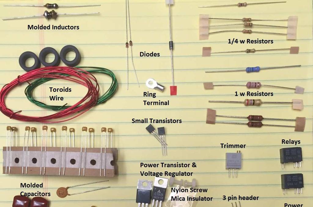
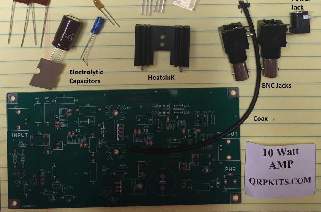
8 Parts Identification V

9 Board Layout V
10 Inserting the Parts Resistors Sort the resistors by value insert them smallest value first, largest value last. Be sure to check the color code for each resistor as you install. [Measuring with an Ohm meter is a good idea.] 1 R3 270 Ω red-vio-brn-gold Resistor, 1/4w 1 R9 10KΩ brn-blk-org-gold Resistor, 1/4w 1 R10 10KΩ brn-blk-org-gold Resistor, 1/4w 1 R11 10KΩ brn-blk-org-gold Resistor, 1/4w 1 R1 100KΩ brn-blk-yel-gold Resistor, 1/4w 1 R5 15 Ω brn-grn-blk-gold Resistor, 1W 1 R4 27Ω red-vio-blk-gold Resistor, 2W 1 R6 ATT Attenuator table Resistor, 2W 1 R7 ATT Attenuator table Resistor, 2W 1 R8" ATT Attenuator table Resistor, 2W Note: See input attenuator table for R6,R7 and R8 values. The kit will be supplied with resistors for 3dB, 6dB and 10dBattenuation levels. You should select the values based on your transmitter output to give approximately 200mW drive to the amplifier. Capacitors First insert the molded capacitors. 1 C1 100pF 101 Disk ceramic capacitor 1 C2 0.1uF 104 (YEL) Capacitor, 1 C3 0.1uF 104 (YEL) Capacitor, 1 C7 0.1uF 104 (YEL) Capacitor, 1 C8 0.1uF 104 (YEL) Capacitor, V
11 1 C11 0.1uF 104 (YEL) Capacitor, 1 C21 0.1uF 104 (YEL) Capacitor, 1 C22 0.1uF 104 (YEL) Capacitor, 1 C23 0.1uF 104 (YEL) Capacitor, 1 C24 0.1uF 104 (YEL) Capacitor, 1 C25 0.1uF 104 (YEL) Capacitor, 1 C26 0.1uF 104 (YEL) Capacitor, 1 C27 0.1uF 104 (YEL) Capacitor, 1 C6 0.1uF 104K (RED) Film Capacitor (Red) 1 C10 0.1uF 104K (RED) Film Capacitor (Red) Electrolytics Now insert the tantalum capacitor and electrolytic capacitors. These capacitors are polarized. The longer lead is the positive + (plus) lead. The positive hole is marked on the circuit board with a + symbol. The shorter lead is the - (minus) lead. The negative lead is also marked with a black bar on the side of the capacitor. 1 C5 4.7uF 4.7 Tantalum Capacitor 1 C4 10uF 10 uf Electrolytic Capacitor 1 C9 1000uF 1000 uf Electrolytic Capacitor Molded Inductors 1 L1 10uH brn-blk-blk-silver Molded inductor, small 1 L2 10uH brn-blk-blk-silver Molded inductor, large Remaining small parts 2 D1 1N (glass) DIODE D3 1N (glass) DIODE V


12 1 Q1 BS170 BS170 N-CHANNEL Mosfet 1 Q3 2N3906 2N3906 PNP Transistor 1 R2 5K R5K Trimmer gray multi turn 1 K1 G5V1 G5V1 RELAY 1 K2 G5V1 G5V1 RELAY The LM317 regulator is mounted to the board using a mica insulator and the a Nylon Screw & Nut. Bend the leads carefully and test fit to the boards. Make sure the tab lies flat and then apply a small amount of heat sink compound to the regulator tab and to the board, place the insulator in place and attach the LM317 using the nylon screw and nut. DO NOT SOLDER the leads until the screw is tight. 1 IC1 LM317MABT 500 ma Voltage Regulator 1 INS Mica Insulator TO-220 Mica insulator 1 SCREW Nylon Screw #4-40 x 1/4 Nylon 1 NUT Nylon Nut #4-40 Nylon Nut Parts on the Heatsink First, solder the heatsink to the board using the 2 large pins. This may require a larger soldering iron or at least operating on the highest temperature setting for small irons. Solder one pin and check that the insulator is flush with the board and vertically straight before soldering the second pin. 1 screw Nylon Screw #4-40 x 1/4 #4-40 x 1/4 Nylon 1 nut Nylon Nut #4-40 #4-40 Nylon Nuts 1 KK1 Heatsink Black finned with PCB pins 1 D2 1N4004 DIODE 1 RT Ring Terminal Flag Ring terminal 1 Q2 2SC1969 NPN RF Power Transistor 1 INS Mica Insulator TO-220 Mica insulator Preparing D2: Diode D2 is used as temperature feedback for the bias current regulator to control thermal drift in the amplifier bias. D2 is mounted, using a flag ring terminal that is supplied in the kit so that it can be attached to the back side of the heatsink for Q2. Using needle nose pliers or screwdrivers, open the wire crimp section of the ring terminal to make a u shaped space for the 1n4004 diode body to fit into the ring terminal. V


13 The ring terminal should fit into the u shaped area formed by opening up the crimp area on the ring terminal. Before crimping down, apply a small amount of heat sink compound to the diode body. Carefully close the u shaped opening around the diode, making sure band is on the left as shown in the picture above. Be careful not to crush the diode. Just in case, a spare diode and ring terminal are included in the kit. Carefully bend the leads of the diode so that they will reach down to the board when the diode is attached to the heatsink. Be careful to keep the leads from shorting to the ring terminal. Insert their respective leads into the board and mount the V
14 ring terminal to the side of the heatsink closest to the diode drawing on the and Q2 to the opposite side using the same nylon screw and nut that hold Q2 to the other side of the heatsink. A mica insulator is placed between Q2 and the heatsink to provide electrical isolation and a thin film of heat sink compound should be used on the tab of Q2 and the heatsink to provide good thermal contact. When both parts are in place, tighten the screw to hold Q2 and the ring terminal holding diode D2 in contact with the heat sink. Once everything is in place and the screw is tight, solder the leads for the transistor and diode D2 to the board. Toroids T1, T2 and T3 are each wound with 14 turns of parallel red and green wire. This will produce a bifiliar transformer with 4 leads. At each end, there will be a red and a green pair of wires. The wires should be stripped and tinned on the ends and then connected to the board by alternating the red and green wires in the board holes from one end to the other of the pads. This means that at one end if you start with the red wire, then the green it is paired with goes in the next board hole, then the red on the other end of the winding followed by the green it is paired with. This will maintain proper phase of the windings. Double check the orientation and then solder the wires to the board. 1 T1 FT50-61 Toroids 14 Turns 4:1 Bifiliar on FT T2 FT50-61 Toroids 14Turns 4:1 Bifiliar on FT T3 FT50-61 Toroids 14 Turns 4:1 Bifiliar on FT50-61 #22 RED Magnet Wire Wire for transformers #22 GREEN Magnet Wire Wire for transformers 1 L3 T50 Toroids See Band Kit table for info 1 L4 T50 Toroid See Band Kit table for info Do not use all the wire for the 3 transformers. You will need part of it for the Coils in the band kit as listed below. Band Kits Inventory Installed Part # 10M +12M 15M +17M 20M 30M 40M M C12, C19 or C20 TBD TBD 150pF 180pF 267pF TBD TBD C14, C15, or C16 150pF 180pF 267pF V
15 C13, C17 or C18 C28 300pf 390pF 560pF 22pF 27pF 44pF C30 C29 C31 51pf 33pF 51pF 33pF 51pF L3 T50-6 T turns T turns T turns T50-2 T50-2 T50-2 L4 T50-6 T turns T turns T turns T50-2 T50-2 T50-2 L3 and L4 are wound with the specified turns of #22 wire. Once wound, strip and tin the ends of the leads, then insert and solder them to the board. V
16 Resistive Attenuator Values You will need to select a value of resistors that gives the desired attenuation level from the table below. You should select the attenuation level that gives approximately mW drive to the amplifier from your transmitter. Note that the attenuator only affects the input power as it is bypassed on receive. R6 R7 R8 Attenuation db db db 3db = 50% reduction: 6dB = 75% reduction: 10dB = 90% reduction: 1W in = 500mw to amplifier 1W in = 250mw to amplifier 1W in = 100mw to amplifier Final Assembly To complete the amplifier board, install a section of coax cable between pads X3 and X5. Note the coax center goes to the upper pads when you are looking at the board from above and the shield goes to the lower pads. This is recommended to be installed on the bottom of the board. This section serves to bypass the amplifier when receiving. Setup and Testing Once the amplifier is assembled, inspect all solder joints checking for good connections and especially, look for any solder bridges or whiskers that may short nearby pads. When first connecting power, it is best to use a power supply with current control or if that is not available, use a 5A or less fuse in the power line to protect the circuitry in case of shorts. V
17 Setting Bias Current In order for the amplifier to operate in a linear mode, bias current is applied to slightly turn on the final transistor. The bias current is set using the trim pot R2. To set the bias, use a multimeter in current measurement mode, placed in series with the positive lead of the DC power. If you have a power supply with an internal current meter it may be used instead of the multimeter. Turn the 10 turn trim pot R2 fully counter clockwise. This may take several turns and there is no stop but you will hear it click as rotated when it as at the end of its range. Connect a dummy load or other 50 ohm load to the output Connect DC power to the amplifier. Key the amplifier using the key input on SV1 PIN 3. (connect Pin3 to ground to key) The current should be close to zero, with only a few milliamps are drawn by the bias regulator and the TR relay. Note the current at this point. ma Adjust R@, the Bias pot, to increase the current drawn by the amplifier to be 100 milliamps greater than the initial current recorded above Troubleshooting If the Amplifier doesn't seem to be working follow the troubleshooting guide below to diagnose the problem. 1). Check that the parts are correctly installed 2). Check the soldering for missed, cold joints or shorts. 3). If the Amplifier keys when grounding pin 3 of SV1 but not from the RF input, check that C1 is the correct value for the band for which the amplifier is built. V
18 4). Check that your exciter is outputting sufficient power to key the amplifier. IF using very low power exciters, use the keying control input on SV1 PIN3. 5). Check that you are operating on the correct band. The amplifier is single band. While it may operate on bands LOWER than the band it was built for, the harmonic content will be out of spec. It will NOT operate on a higher band that what it was built for. 6). If there is no receive signals, check that the coax jumper is installed on the back of the Amplifier PCB. 7) Check the power draw of the amplifier. Maximum should be less than 3A and typically approximately 1-2 Amps when keyed. If bias is too high, the measured current draw may exceed 2A. In this case, recheck the bias setting. V


19 Low Pass Filter Response 20M 30M 40M V
20 Schematic Diagram V
Read This Page First
 Pacific Antenna 0 Watt HF Amplifier Kit Manual This is Version 5.5 dated 060505 Read This Page First If you are reading this you know the manuals are always available at QRPKITS.com. If you have questions
Pacific Antenna 10 Watt HF Amplifier Kit
 Pacific Antenna 0 Watt HF Amplifier Kit Description Our 0 watt Linear, HF amplifier kit is designed to increase the power output of low power transmitters. Gives up to 5dB gain and includes an input attenuator
Read This Page First
 Read This Page First If you are reading this you know the manuals are always available at QRPKITS.com. This is version 8.0 of the manual dated 4/27/2016. There is no need to print out the whole assembly
Easy Transmitter. Support ETX_REV5_Manual V2.7 Revised
 Easy Transmitter Introduction The Easy Transmitter kit from qrpkits.com provides a basic, crystal controlled transmitter with VXO tuning to provide a small tuning range around the crystal frequency. It
Pacific Antenna Easy Transmitter Kit
 Pacific Antenna Easy Transmitter Kit Introduction The Easy Transmitter kit from qrpkits.com provides a crystal controlled transmitter with VXO tuning. The circuit consists of a N3904 based crystal oscillator
Pacific Antenna - Easy TR Switch
 Pacific Antenna - Easy TR Switch Kit Description The Easy TR Switch is an RF sensing switch that can be used to switch an antenna between a receiver and transmitter. It also has a second switched pair
Pacific Antenna Easy TR Switch
 Pacific Antenna Easy TR Switch Kit Description The Easy TR Switch is an RF sensing circuit with a double pole double throw relay that can be used to automatically switch an antenna between a separate receiver
LED Field Strength Indicator Kit
 LED Field Strength Indicator Kit Description The Field Strength Indicator kit from Qrpkits.com provides a visual way to monitor RF fields through the brightness of an LED. It will respond to RF fields
Pacific Antenna Low Pass Filter Kit
 Pacific Antenna Low Pass Filter Kit Description Many basic transmitter and/or transceiver designs have minimal filtering on their output and frequently have significant harmonic content in their signals.
Pacific Antenna Easy SWR Indicator Kit
 Pacific Antenna Easy SWR Indicator Kit Description Monitoring the match of an antenna to your transmitter or adjusting an antenna tuner for best match requires an indicator of the reflected power as an
Pacific Antenna Field Strength Indicator Kit
 Pacific Antenna Field Strength Indicator Kit Description The Field Strength Indicator kit from Pacific Antenna provides a visual way to monitor the presence and relative strength RF fields through the
Assembly Instructions for the 1.5 Watt Amplifier Kit
 Assembly Instructions for the 1.5 Watt Amplifier Kit 1.) All of the small parts are attached to a sheet of paper indicating both their value and id. 2.) Leave the parts affixed to the paper until you are
Pacific Antenna Wall Wart Tamer 2.0 Kit
 Pacific Antenna Wall Wart Tamer 2.0 Kit Description The Wall Wart Tamer lets you utilize those surplus computer and wall pack power supplies as a clean, adjustable voltage, DC power source for radios and
Assembly Instructions for the FRB FET FM 70 Watt Amp
 Assembly Instructions for the FRB FET FM 70 Watt Amp 1.) Orient the circuit board with the diagram 2.) Use a narrow chisel tip 25-30 watt soldering iron for assembly 3.) All the small parts are taped onto
Step by Step Building PJ meter ARDF Receiver Kit. CRKITS.COM August 5, 2013
 Step by Step Building PJ-80 80-meter ARDF Receiver Kit CRKITS.COM August 5, 2013 What is ARDF? ARDF is the abbreviation of Amateur Radio Direction Finding, or so called Fox Hunting. If you are looking
PM24 Installation Instructions
 Marchand Electronics Inc. PO Box 473, Webster, NY 14580 Tel:(716) 872-0980 Fax:(716) 872-1960 info@marchandelec.com http://www.marchandelec.com (c)1997 Marchand Electronics Inc. PM24 Installation Instructions
QRPme.com Kits. Tx/Tuna Topper. Assembly and Operation Guide. Kits for the QRP and Electronics Hobbyist. Heatsink left off for better assembly viewing
 QRPme.com Kits Kits for the QRP and Electronics Hobbyist Tx/Tuna Topper Heatsink left off for better assembly viewing QRMme.com Kits Tx/Tuna Topper Contents Figures and Illustrations...............................
Pacific Antenna RF Probe assembly
 Pacific Antenna RF Probe assembly Parts In the Kit: 1 1/2 x 3 Blue PEX tube 2 5/8 O.D. vinyl caps 2 3/32 dia x 2 brass tube sections 2 Pogo spring contacts 1 4-40 x 7/16 pan head screw 1 4-40 x 1/4 pan
QRPme.com Kits. Tx/Tuna Topper. Assembly and Operation Guide. Kits for the QRP and Electronics Hobbyist. Heatsink left off for better assembly viewing
 QRPme.com Kits Kits for the QRP and Electronics Hobbyist Tx/Tuna Topper Heatsink left off for better assembly viewing Contents Figures and Illustrations............................... 3 Jumpers............................................
Pacific Antenna 20 and 40M Lightweight Dipole Kit
 Pacific Antenna 20 and 40M Lightweight Dipole Kit Antenna diagram showing configuration and lengths when assembled 7 8 16 9 16 9 Description The Pacific Antenna lightweight dual band dipole kit provides
Hendricks QRP Kits The Twofer Rev
 Hendricks QRP Kits The Twofer Rev 1 11-15-06 1. Description The Twofer is a classic QRP transmitter that s easy to assemble and operate. It uses a JFET VXO (variable crystal oscillator), driver stage and
Building the Sawdust Regenerative Receiver
 Building the Sawdust Regenerative Receiver Introduction The Sawdust is a super regenerative receiver using the basic Armstrong design architecture. The receiver uses one toroidal transformer to provide
DIODE / TRANSISTOR TESTER KIT
 DIODE / TRANSISTOR TESTER KIT MODEL DT-100K 99 Washington Street Melrose, MA 02176 Phone 781-665-1400 Toll Free 1-800-517-8431 Visit us at www.testequipmentdepot.com Assembly and Instruction Manual Elenco
PM124 Installation Instructions. See important note about revisions of this board on the last page.
 Marchand Electronics Inc. PO Box 473, Webster, NY 14580 Tel:(716) 872-0980 Fax:(716) 872-1960 info@marchandelec.com http://www.marchandelec.com (c)1997 Marchand Electronics Inc. PM124 Installation Instructions
Building the Sawdust Regenerative Receiver
 Building the Sawdust Regenerative Receiver Introduction The Sawdust is a super regenerative receiver using the basic Armstrong design architecture. The receiver uses one toroidal transformer to provide
Assembly Instructions
 Assembly Instructions For the SSQ-2F 3.1 MHz Rife Controller Board Kit v1.41 Manual v1.00 2012 by Ralph Hartwell Spectrotek Services GENERAL ASSEMBLY INSTRUCTIONS Arrange for a clean work surface with
Building a Bitx20 Version 3
 Building a Bitx20 Version 3 The board can be broken into sections and then built and tested one section at a time. This will make troubleshooting easier as any problems will be confined to one small section.
DIODE / TRANSISTOR TESTER KIT
 DIODE / TRANSISTOR TESTER KIT MODEL DT-100K Assembly and Instruction Manual Elenco Electronics, Inc. Copyright 1988 Elenco Electronics, Inc. Revised 2002 REV-K 753110 DT-100 PARTS LIST If you are a student,
Instructions for Building the Pulsed Width Modulation Circuit. MC-12 (DC Motor Controller or PWM) From Electronic Light Inc. (revised kit 10/03/08)
 From Electronic Light Inc. (revised kit 10/03/08)") Instructions for Building the Pulsed Width Modulation Circuit MC-12 (DC Motor Controller or PWM) From Electronic Light Inc. (revised kit 10/03/08) Congratulations on your purchase of the MC-12 DC Motor
Instructions for Building the Pulsed Width Modulation Circuit MC-12 (DC Motor Controller or PWM) From Electronic Light Inc. (revised kit 10/03/08) Congratulations on your purchase of the MC-12 DC Motor
HT-1A Dual Band CW QRP Transceiver. Kit Building Instructions
 HT-A Dual Band CW QRP Transceiver Kit Building Instructions Rev B, July 8, 08 Designed by BD4RG Exclusively distributed by CRKITS.COM and its worldwide distributors Join the group http://groups.io/g/crkits
Bill of Materials: PWM Stepper Motor Driver PART NO
 PWM Stepper Motor Driver PART NO. 2183816 Control a stepper motor using this circuit and a servo PWM signal from an R/C controller, arduino, or microcontroller. Onboard circuitry limits winding current,
SUPER Tuna ][+ Builder s Guide
![SUPER Tuna ][+ Builder s Guide](/thumbs/72/66369453.jpg "SUPER Tuna ][+ Builder s Guide") SUPER Tuna ][+ Builder s Guide Ver2.3 Rex Harper W1REX 3/25/2015 The first thing you should do is to familiarize yourself with what you are going to build. The previous 3 pages are schematics of the
SUPER Tuna ][+ Builder s Guide Ver2.3 Rex Harper W1REX 3/25/2015 The first thing you should do is to familiarize yourself with what you are going to build. The previous 3 pages are schematics of the
Arizona ScQRPion QRP Club. Ft Tuthill w DC CW Transceiver for 80m Part 1 of 2. by Dan Tayloe, N7VE. Ft Tuthill Page 1 of 31
 Arizona ScQRPion QRP Club Ft Tuthill 80 2.5w DC CW Transceiver for 80m Part 1 of 2 by Dan Tayloe, N7VE Page 1 of 31 Table of Contents Specifications... 4 Specifications... 4 Receiver... 4 Transmitter...
WA3RNC 30 METER CRYSTALPLEXER TRANSMITTER KIT ASSEMBLY INSTRUCTIONS
 WA3RNC 30 METER CRYSTALPLEXER TRANSMITTER KIT ASSEMBLY INSTRUCTIONS Description The WA3RNC 30 Meter Crystalplexer is a low power crystal controlled QRP transmitter offering a significantly improved tuning
Stand Alone VXO (SAVXO) Assembly Manual Manual Version 1.0B_
 Assembly Manual Manual Version 1.0B_") Stand Alone VXO (SAVXO) Assembly Manual Manual Version.0B_0-6-0 Designed by: Jim Kortge, K8IQY Kitted & Sold by: 4 State QRP Group Copyright: 0 Forward Thank you for purchasing a 4 State QRP Group Stand
Stand Alone VXO (SAVXO) Assembly Manual Manual Version.0B_0-6-0 Designed by: Jim Kortge, K8IQY Kitted & Sold by: 4 State QRP Group Copyright: 0 Forward Thank you for purchasing a 4 State QRP Group Stand
SoftRock v6.0 Builder s Notes. May 22, 2006
 SoftRock v6.0 Builder s Notes May 22, 2006 Be sure to use a grounded tip soldering iron in building the v6.0 SoftRock circuit board. The soldering iron needs to have a small tip, (0.05-0.1 inch diameter),
Pacific Antenna 20 and 40M Lightweight Dipole Kit
 Pacific Antenna 20 and 40M Lightweight Dipole Kit Diagram showing configuration and approximate lengths 8 3 16 9 16 9 8 3 Description The Pacific Antenna lightweight dual band, trap dipole kit provides
Pacific Antenna 20 and 40M Lightweight Dipole Kit
 Pacific Antenna 20 and 40M Lightweight Dipole Kit Diagram showing configuration and approximate lengths 8 6 16 9 16 9 8 6 Description The Pacific Antenna lightweight dual band, trap dipole kit provides
KN-Q10 Assembly Manual
 KN-Q10 Assembly Manual Translated by Adam Rong, BD6CR/4 with permission from Ke Shi, BA6BF Edited by Stephen, VK2RH Revision B, Oct 14, 2010 Thank you for purchasing the KN-Q10 4 Band SSB/CW Dual Mode
SoftRock v6.0 Builder s Notes. April 6, 2006
 SoftRock v6.0 Builder s Notes April 6, 006 Be sure to use a grounded tip soldering iron in building the v6.0 SoftRock circuit board. The soldering iron needs to have a small tip, (0.05-0. inch diameter),
IR add-on module circuit board assembly - Jeffrey La Favre January 27, 2015
 IR add-on module circuit board assembly - Jeffrey La Favre January 27, 2015 1 2 For the main circuits of the line following robot you soldered electronic components on a printed circuit board (PCB). The
Bitx Version 3 Linear Amplifier Assembly
 Bitx Version 3 Linear Amplifier Assembly The power supply section has 2 options. 1 - AC input and a higher voltage on the IRF510 and +12 volts to the bitx. 2 - +12 volts applied to both the final and the
SoftRock v5.0 Builder s Notes. December 12, Building a QSD Kit
 SoftRock v5.0 Builder s Notes December 12, 2005 Building a QSD Kit Be sure to use a grounded tip soldering iron in building the QSD board. The soldering iron needs to have a small tip, (0.05-0.1 inch diameter),
10W HF Linear PA. A low-cost, high-performance HF Linear PA covering 2-30MHz. 10W HF Linear Power Amplifier kit assembly manual
 10W HF Linear PA 10W HF Linear Power Amplifier kit assembly manual A low-cost, high-performance HF Linear PA covering 2-30MHz Designed and produced by QRP Labs, 2018 10W HF Linear PA kit assembly 1.01
Instructions for Building the Pulsed Width Modulation Circuit. MC-12 (DC Motor Controller or PWM) From Electronic Light Inc. (revised kit 8/08)
 From Electronic Light Inc. (revised kit 8/08)") Instructions for Building the Pulsed Width Modulation Circuit MC-12 (DC Motor Controller or PWM) From Electronic Light Inc. (revised kit 8/08) Using this circuit for a pulsed DC current to your cell. Do
Instructions for Building the Pulsed Width Modulation Circuit MC-12 (DC Motor Controller or PWM) From Electronic Light Inc. (revised kit 8/08) Using this circuit for a pulsed DC current to your cell. Do
PAT-4 POWER SUPPLY ASSEMBLY MANUAL Rev B Version
 PAT-4 POWER SUPPLY ASSEMBLY MANUAL Rev B Version 2013 AkitikA, LLC All rights reserved Revision Bp01 November 3, 2013 Page 1 of 16 Table of Contents Table of Contents... 2 Table of Figures... 2 Section
LPF-9B Nine band low pass filter module kit ( meters)
") LPF-9B Nine band low pass filter module kit (80-60-40-30-20-17-15-12-10 meters) Assembly manual Last update: March 1, 2018 ea3gcy@gmail.com Most recent updates and news at: www.ea3gcy.com Thanks for constructing
LPF-9B Nine band low pass filter module kit (80-60-40-30-20-17-15-12-10 meters) Assembly manual Last update: March 1, 2018 ea3gcy@gmail.com Most recent updates and news at: www.ea3gcy.com Thanks for constructing
Time of Arrival Radio Direction Finder.
 Time of Arrival Radio Direction Finder. Time of arrival (TOA) RDF units are simple and very useful. Various designs have been distributed over the years, and here is another one. This Kit Developed by
REPAIRING THE RM KL400 LINEAR AMPLIFIER.
 REPAIRING THE RM KL400 LINEAR AMPLIFIER. Les Carpenter G4CNH December 2012 Page 1 of 20 The following is a step by step guide to fixing your KL400 amplifier. Each part will be individually tested up to
Value Location Qty Potentiometers C1M Distortion 1 A10k Volume 1. Footswitch 3PDT SW1 1. Jacks 1/4 Mono 2 DC Power 1
 Distortion BUILD INSTRUCTIONS Thank you for your purchase of our Distortion+ kit! We have completely redesigned our entire line of kits to be the most user friendly, while still maintaining their same
Ten Tec DDS Board Assembly Procedure
 05 May 2014 Ten Tec DDS Board Assembly Procedure You will find a photo of a completed board at the end of these instructions. Refer it whenever clarification is required. 1. AD9835 Attachment If you purchased
HW-8-TR V3 PARTS LIST
 HW-8-TR V3 PARTS LIST Qty Ref Description Markings 4C2 C3 C4 C5 Capacitor Disc.1ls.1uF 104 1 C1 Capacitor Disc.2ls.1uF 100V 104 1 QSKMOD-C92 Capacitor Electrolytic 1uF 50V 1 QSKMOD Capacitor Mylar.47uF
ASSEMBLY MANUAL FOR R3500D DIRECTION FINDING RECEIVER KIT
 SDR-Kits www.sdr-kits.net SDR-Kits is CRKITS Authorised Distributor for Europe ASSEMBLY MANUAL FOR R3500D DIRECTION FINDING RECEIVER KIT Rev. A May 24, 2015 Written by CRKITS http://www.crkits.com Thanks
Xkitz.com XLO-5CP Control Panel for Five Channel Color Light Organ
 Xkitz.com XLO-5CP Control Panel for Five Channel Color Light Organ Rev 1.15 An Optional accessory for the Xkitz XLO-5 or XLO-5DC 5 Channel Color Light Organs Introduction This kit contains all the electronics
Construction notes for the symmetrical 400 watt amplifier
 Construction notes for the symmetrical 400 watt amplifier Introduction The symmetrical amplifier is an update of one of my designs, which appeared in the Australian electronics magazine Silicon Chip in
Assembly Instructions
 Assembly Instructions for the PA3 v2.0 Amplifier Kit PA3 Amplifier shown mounted on HS2 Heat Sink (The HS2 shown here is not included with this kit.) 27 February 2016 2013-2016 by Ralph Hartwell Spectrotek
HAMTRONICS LPA 2-25R REPEATER POWER AMPLIFIER: ASSEMBLY, INSTALLATION, & MAINTENANCE
 HAMTRONICS LPA 2-25R REPEATER POWER AMPLIFIER: ASSEMBLY, INSTALLATION, & MAINTENANCE GENERAL INFORMATION. The Power Amplifier is a class C device designed to be installed as an integral part of a transmitter
Build this Direct Digital Synthesizer "Development Kit" By: Diz Gentzow, W8DIZ
 Build this Direct Digital Synthesizer "Development Kit" By: Diz Gentzow, W8DIZ A great tutorial for adding a keypad to the DDS Kit by Bruce, W8BH This manual has been prepared to be read directly on screen.
MINI FM PHONE TRANSMITTER KIT
 MINI FM PHONE TRANSMITTER KIT Description: This is a subminiature FM telephone transmitter capable of transmitting both sides of a telephone conversation to most any FM receiver up to 1/4 mile away. When
Instructions for Building the Pulsed Width Modulation Circuit. MC-12 (DC Motor Controller or PWM) From Electronic Light Inc.
 From Electronic Light Inc.") Instructions for Building the Pulsed Width Modulation Circuit MC-2 (DC Motor Controller or PWM) From Electronic Light Inc. (revised 3/08) Using this circuit for a pulsed DC current to your cell, Do NOT
Instructions for Building the Pulsed Width Modulation Circuit MC-2 (DC Motor Controller or PWM) From Electronic Light Inc. (revised 3/08) Using this circuit for a pulsed DC current to your cell, Do NOT
Enhancing Your QRP Operating Enjoyment
 QRP-DWM Directional-Coupler Watt Meter Preliminary By: W5USJ CyM-Tech Documentation Services Enhancing Your QRP Operating Enjoyment PCB Assembly Top View Addendum: Correct missing toroid ground after installing
Guitarpedalkits.com Overdrive Pedal Build Instructions
 Page 1 Guitarpedalkits.com Overdrive Pedal Build Instructions Follow the instructions in this guide to build your very own DIY overdrive pedal from GuitarPedalKits.com. If you re a first time builder,
Instructions for Building the Pulsed Width Modulation Circuit. MC-12 (DC Motor Controller or PWM) From Electronic Light Inc. (revised kit 5/08)
 From Electronic Light Inc. (revised kit 5/08)") Instructions for Building the Pulsed Width Modulation Circuit MC-12 (DC Motor Controller or PWM) From Electronic Light Inc. (revised kit 5/08) Using this circuit for a pulsed DC current to your cell. Do
Instructions for Building the Pulsed Width Modulation Circuit MC-12 (DC Motor Controller or PWM) From Electronic Light Inc. (revised kit 5/08) Using this circuit for a pulsed DC current to your cell. Do
Enhancing Your QRP Operating Enjoyment
 QRP-DPM Directional-Coupler Power Meter Preliminary By: W5USJ CyM-Tech Documentation Services Enhancing Your QRP Operating Enjoyment PCB Assembly Top View Addendum: No Changes. The QRP-DPM Directional-
Value Location Qty Transistors 2N5485 Q1, Q2, 4 Q3, Q4 2N5087 Q5 1. Trim Pots 250k VTRIM 1. Potentiometers C500k Speed 1. Toggle Switch On/On Vibe 1
 P-90 BUILD INSTRUCTIONS Thank you for your purchase of our P-90 kit! We have completely redesigned our entire line of kits to be the most user friendly, while still maintaining their same great sound!
V6.2 SoftRock Lite Builder s Notes. November 17, 2006
 V6.2 SoftRock Lite Builder s Notes November 17, 2006 Be sure to use a grounded tip soldering iron in building the v6.2 SoftRock circuit board. The soldering iron needs to have a small tip, (0.05-0.1 inch
LITTLE NERD v1.1 Assembly Guide
 last update: 9. 3. 2016 LITTLE NERD v1.1 Assembly Guide bastl instruments.com INTRODUCTION This guide is for building Little Nerd module from Bastl Instruments. It is good to have basic soldering skills
MP573 Assembly guide. Soldering. MP573 Assembly guide PCB split PCB split. Document revision 2.2 Last modification : 22/08/17
 MP573 Assembly guide Safety warning The kits are main powered and use potentially lethal voltages. Under no circumstance should someone undertake the realisation of a kit unless he has full knowledge about
Building the Toothpick Audio CW Filter
 Building the Toothpick Audio CW Filter Introduction The toothpick is a simple variable bandpass audio filter designed to compliment the Splinter QRPp Trans-Receiver. The filter also contains an audio amplifier
Tuna Tunah. Switched Inductor Antenna Tuner. Builder's Guide by Kevin Gilot NZ1I & Rex Harper W1REX. version 1.2
 Tuna Tunah Switched Inductor Antenna Tuner Builder's Guide by Kevin Gilot NZ1I & Rex Harper W1REX version 1.2 Tuna Tunah List of Materials Qty Description PCB Location ( ) 1-.22uH Inductor (Red-Red-Silver).22
12kHz LIF Converter V2.43 9Mhz version
 12kHz LIF Converter V2.43 9Mhz version Please Note: This document supersedes all previously released documents and drawings on the LIF subject. This is the latest and most up-to-date document at this time.
THE RING RESONATOR (K-975)
") THE RING RESONATOR (K-975) OUTPUT BOOST The Ring Resonator An Octave Up Fuzz Modkitsdiy.com 9 VDC CENTER (-) ADAPTER TO AMP IN FROM GUITAR OUT Unplug when not in use to save battery life. Use these instructions
THE RING RESONATOR (K-975) OUTPUT BOOST The Ring Resonator An Octave Up Fuzz Modkitsdiy.com 9 VDC CENTER (-) ADAPTER TO AMP IN FROM GUITAR OUT Unplug when not in use to save battery life. Use these instructions
Balanced Modulator. Model 9748 Assembly and Using Manual PAiA Corporation
 Balanced Modulator Model 9748 Assembly and Using Manual This second-generation 9700-series processing element for modular sound synthesizers is designed to provide great sound and excellent value. Audio
S-Pixie QRP Kit. Student Manual. Revision V 1-0
 S-Pixie QRP Kit Student Manual Revision V 1-0 Introduction The Pixie 2 is a small, versatile radio transceiver that is very popular with QRP (low power) amateur radio operators the world over. It reflects
The Walford Electronics Ford Receiver Kit Project Construction Manual
 The Walford Electronics Ford Receiver Kit Project Construction Manual Walford Electronics Ford Receiver construction manual V1.5 Page 1 of 22 Introduction The Ford receiver has four stages: The first stage
Cricket 80a Assembly Manual v Copyright David Cripe NM0S The 4 State QRP Group
 Cricket 80a Assembly Manual v. 1.0 Copyright 2017 David Cripe NM0S The 4 State QRP Group Introduction Thank you for purchasing a CRICKET 80a Transceiver. We hope you will enjoy building it and find it
TS500 Assembly guide. Soldering. TS500 Assembly guide Main PCB 1. Diodes. Document revision 1.2 Last modification : 17/12/16
 TS500 Assembly guide Safety warning The kits are main powered and use potentially lethal voltages. Under no circumstance should someone undertake the realisation of a kit unless he has full knowledge about
BP-1A. Band-Pass variable filter continuous tuning from 3 to 30MHz. For analogue or software-defined receivers (SDR) Assembly manual
 Assembly manual") BP-1A Band-Pass variable filter continuous tuning from 3 to 30MHz. For analogue or software-defined receivers (SDR) Assembly manual Last updated: December 1, 2017 ea3gcy@gmail.com Updates and news at:
BP-1A Band-Pass variable filter continuous tuning from 3 to 30MHz. For analogue or software-defined receivers (SDR) Assembly manual Last updated: December 1, 2017 ea3gcy@gmail.com Updates and news at:
Assembly Manual V1R2B-Rev1.0D
 Assembly Manual V1R2B-Rev1.0D for 4 State QRP MagicBox - Solid State Transmit/Receive System Designed by: Jim Kortge, K8IQY Copyright 2009-2012 - All rights reserved This system is the result of some brainstorming
400W MONO/STEREO AMPLIFIER
 400W MONO/STEREO AMPLIFIER Universal, robust and compact are the words to describe this amplifier. Total solder points: 264 Difficulty level: beginner 1 2 3 4 5 advanced K4005B ILLUSTRATED ASSEMBLY MANUAL
TekBot Remote Control Receiver Board Construction
 TekBot Remote Control Receiver Board Construction Purpose This tutorial illustrates the procedure for construction of the Receiver board for the TekBot. A Guide to Soldering Many of you have soldered once
IPR LA-3 KIT last update 15 march 06
 IPR LA-3 KIT last update 15 march 06 PART-2: Audio Circuitry CIRCUIT BOARD LAYOUT: Power and Ground Distribution Now that your power supply is functional, it s time to think about how that power will be
ABC V1.0 ASSEMBLY IMPORTANT!
 ABC V1.0 ASSEMBLY Before starting this kit, prepare the following tools: Soldering iron (15-20W will do), flush cutters, no.2 hex screwdriver or allen key and phillips screwdriver. Also briefly go through
Building and Operating: LF Converter An SA612 based LF up-converter from Jackson Harbor Press
 Introduction: Building and Operating: LF Converter An SA612 based LF up-converter from Jackson Harbor Press The frequencies below the broadcast band are covered by few receivers on the market - those that
TKEY-1. CW touch key. (no electromechanical contacts) Assembly manual. Last update: May 1,
 Assembly manual. Last update: May 1,") TKEY-1 CW touch key (no electromechanical contacts) Assembly manual Last update: May 1, 2016 ea3gcy@gmail.com Updates and news at: www.qsl.net/ea3gcy Thanks for constructing the TKEY-1A CW touch key Have
TKEY-1 CW touch key (no electromechanical contacts) Assembly manual Last update: May 1, 2016 ea3gcy@gmail.com Updates and news at: www.qsl.net/ea3gcy Thanks for constructing the TKEY-1A CW touch key Have
Manual Version July 2007
 Manual Version 1.2 - July 2007 Page 1 Table of Contents Section1: M3 Phono Board Build...3 Phono Board Parts List...3 Preparation...4 Fitting the Valve Bases...6 Installing the Resistors...7 Starting the
RF Current Meter Kit
 Kit When assembled, this kit provides you with a simple but effective means of measuring the current in antenna wires, and of looking for braid currents on coax feeders. The more current you can get flowing
10W Class D Ultra Stereo Amplifier Kit
 1 Total Solder Joints: 70 Difficulty Level : beginner expert PARADIGM Technologies (UK) Ltd Electronic Kits and Modules 10W Class D Ultra Stereo Amplifier Kit K1421 High power / quality audio amplifier
Solder Practice Kit MODEL AK-100. Elenco Electronics, Inc. Lesson Manual. Elenco Electronics, Inc.
 Solder Practice Kit MODEL AK-100 Elenco Electronics, Inc. 150 W. Carpenter Avenue Wheeling, IL 60090 (847) 541-3800 http://www.elenco.com e-mail: elenco@elenco.com Lesson Manual Elenco Electronics, Inc.
Line-Following Robot
 1 Line-Following Robot Printed Circuit Board Assembly Jeffrey La Favre October 5, 2014 After you have learned to solder, you are ready to start the assembly of your robot. The assembly will be divided
PAT-4 UPGRADES ASSEMBLY MANUAL
 PAT-4 UPGRADES ASSEMBLY MANUAL Line amp distortion reducer Tone control switch 2013 AkitikA, LLC All rights reserved Revision 1p92 May 1, 2013 Page 1 of 20 Table of Contents Table of Contents... 2 Table
Audio Bi-Amplifier, 200W/100W, 2-Way Active Crossover
 Audio Bi-Amplifier, 200W/100W, 2-Way Active Crossover Model XAMP-M4 Assembly and Operator s Manual Rev 1.1.2 Xkitz.com Features On-board 2-way active crossover drives dual amplifiers for separate woofer
Project 747 VERSION 1.3 USER MANUAL February 22nd 2018
 VERSION 1.3 USER MANUAL February 22nd 2018 WWW.GARAGE1217.COM WARNING: Project requires knowledge of AC electrical systems, repair of said systems and restoration of said systems. If proper safety measures
THE THUNDERDRIVE (K-950)
") THE THUNDERDRIVE (K-950) OUTPUT DISTORTION Unplug when not in use to save battery life. TO AMP IN The Thunderdrive Modkitsdiy.com FROM GUITAR OUT Use these instructions to learn: How to build an effects
THE THUNDERDRIVE (K-950) OUTPUT DISTORTION Unplug when not in use to save battery life. TO AMP IN The Thunderdrive Modkitsdiy.com FROM GUITAR OUT Use these instructions to learn: How to build an effects
GT100 TWO CHANNEL AUDIO POWER AMPLIFIER ASSEMBLY MANUAL
 GT100 TWO CHANNEL AUDIO POWER AMPLIFIER ASSEMBLY MANUAL 2012 AkitikA, LLC All rights reserved Revision 1p30 June 24, 2012 Page 1 of 44 Table of Contents Table of Contents... 2 Table of Figures... 3 Section
12V Dimmer Kit, version 2
 12V Dimmer Kit, version 2 User Manual Description The 12V Dimmer Kit V2 is an especially efficient PWM (pulse-width modulation) controller for 12V loads up to 60 watts. It features a single dial control
Polyphase network kit
 Polyphase network kit 1. Introduction This polyphase network module is designed to be used with the QRP Labs receiver module kit. It takes as inputs, four phase audio from the Quadrature Sampling Detector
Penrose Quantizer Assembly Guide
 Penrose Quantizer Assembly Guide Schematic and BOM The schematic can be found here: www.sonic-potions.com/public/penrosequantizerschematic.pdf The BOM is available at google docs: Link to BOM Prepare the
CW-ADD. Universal CW Adapter for SSB Transceivers. Assembly manual. Last updated: October 1,
 CW-ADD Universal CW Adapter for SSB Transceivers Assembly manual Last updated: October 1, 2017 ea3gcy@gmail.com Updates and news at: www.ea3gcy.com Thanks for building the Universal CW Adapter kit CW-ADD