FM Audio/Squelch Board by Steve Dold, W6KCS w6kcs (at) stevedold (dot) com
|
|
|
- Branden Crawford
- 5 years ago
- Views:
Transcription
1 FM Audio/Squelch Board by Steve Dold, W6KCS w6kcs at stevedold dot com Board hardware version 7-8 Firmware version 7.x This board connects to an FM receiver's discriminator/detector and provides squelched, de-emphasized, CTCSS-filtered audio and an active-high or low carrier operated switch COS output for driving repeater controllers or other devices. A speaker amplifier with volume control is also provided. This board requires only a single connection to the receiver's discriminator, and provides: COS output active high or low, jumper-selectable CTCSS-filtered, de-emphasized audio to drive a repeater controller or other device Speaker amplifier with on-board volume control, and provision for external volume control On-board squelch control Space on the board to install an optional CTCSS PL decoder Separate CTCSS logic output available for repeater controllers that use separate COS and CTCSS logic inputs if optional CTCSS board is installed When a CTCSS board is installed, optional temporary carrier-squelch operation when CTCSS is decoded and/or a transmitter is keyed useful for a link or remote base The squelch tail noise burst length varies depending on the amount of receiver noise quieting. The length is about 5 milliseconds with a signal that is nearly full quieting and about 50 milliseconds with a noisy signal. The squelch has hysteresis; a signal that is just strong enough to open the squelch must drop by about - db in strength for the squelch to close. These features allow the squelch to stay open on signals that are picket fencing rapidly. The method used for gating the audio ensures that no pops due to DC voltage changes, capacitor charging/discharging etc. occur when squelching or unsquelching, so the squelch tail is fairly quiet, being purely receiver noise. Space is provided on the board to mount a CTCSS decoder such as a Comm-Spec TS-3 or TS-64. All of the necessary connections to the CTCSS board are provided as solder pads so that all of the interfacing to the outside repeater controller, etc. can be done using the -position terminal strip on the squelch board. If the CTCSS board is installed, several options are available for its operation: Carrier-squelch mode for one minute after decoding a valid CTCSS tone. This is useful if it is not necessary to have full-time CTCSS protection, for example: A link receiver switching to carrier-squelch mode during a conversation to minimize the decode-time of the system so that the first words of transmissions are not cut off. A repeater protected with CTCSS when sitting idle, but going into temporary carrier squelch mode when it's being used so that users without CTCSS can join in. Carrier-squelch mode for one minute after a transmitter has been keyed, useful for: The above-mentioned case of a link receiver, to put it into carrier-squelch temporarily when its associated transmitter has been keyed. A remote base receiver where you'd like to have CTCSS protection most of the time, but want it to go into carrier-squelch mode temporarily when the transmitter is keyed.
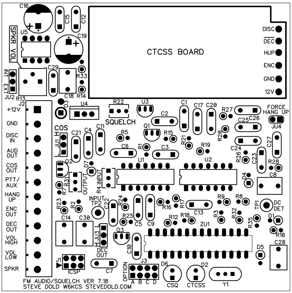
2 Installation A plastic mounting plate with standoffs has been provided. The plate may be attached to any surface by drilling holes where needed, using double-sided tape, etc. Be sure to leave room for trimmer adjustments and terminal block screwdriver access. Connections All external connections are made to the -position terminal strip: PIN FUNCTION +V +V to +8V DC in GND Ground 3 DISC IN 4 AUD OUT Audio out to a repeater controller or other external device requiring low-level audio. 5 COS OUT Carrier Operated Switch, an active-low or active-high output set by JU when carrier squelch is open signal present. 6 PTT/AUX Auxiliary input to the microcontroller logic input. In this firmware version, connected to a transmitter's PTT line if using Options B, C and/or D. 7 HANG UP Internally connects to the microphone hang-up line on the CTCSS decoder board, if installed. Ground this line to enable CTCSS decoder CTCSS squelch, unground to disable carrier squelch. Typically controlled by repeater controller open-collector on/off logic output or tie to ground for full-time CTCSS squelch. Note that there is a jumper on the board JU-4 that also does this if you want the CTCSS decoder to be permanently on hook. Be sure to remove JU-4 if you plan to externally control CTCSS/Carrier squelch mode using this connection. 8 ENC OUT CTCSS Encoder output. This can be used to route the CTCSS board's encode tone output if used to a transmitter. 9 DEC OUT CTCSS Decode. An active-low or active-high output set by JU3 when CTCSS decoder if installed is decoding the proper tone. 0 VOL HIGH To the high side of an external speaker volume pot if used, JU must also be set to EXT and the internal volume control set to max level desired. VOL LOW From wiper of external speaker volume pot. Also connect the low side of the pot to ground. SPKR Input to the board from the receiver's discriminator; connect to the receiver's audio before any squelch or de-emphasis circuitry. The high side of the radio's squelch pot is often a good place to connect. To high side of external 8 ohm speaker. Connect other side of speaker to ground. =
3 Circuit Description Discriminator audio is applied to J, terminal 3. This audio goes to three circuits: a 4000 Hz high pass filter, a 350 Hz high pass filter, and the CTCSS board if installed. The 4000 Hz high-pass filter U removes the voice audio, leaving the high-frequency noise component that is present on weak signals or no signal. The noise is detected by D and D4, and filtered by C8 and R0. The detected noise level is monitored by the microcontroller ZU which controls audio squelch gate U.4 via Q. The detected level can be monitored on TP with a voltmeter or an oscilloscope. It should be about 4.5V with no signal full noise and 0V with a full-quieting signal. When the microcontroller senses a reduction in detected noise level, it opens the audio squelch gate U.4 and sends an active-high COS signal to J terminal 5, either directly or through inverter Q which changes the COS output to an active-low open collector. When the signal becomes weak or disappears, the microcontroller squelches the audio and de-activates the COS after about 50 milliseconds if the signal was noisy, or about 5 milliseconds if the signal was close to full quieting. 3
4 The discriminator audio also passes through input buffer amp U., then through 350 Hz high-pass filter U. and U.3 that mostly removes any CTCSS component. The audio then passes through the squelch gate/de-emphasis circuit U.4 and on to J-4 to feed an external repeater controller or other device. Part of this audio also feeds speaker amplifier U5. Special-case modifications: If you do not want the board to de-emphasize the audio, remove capacitor C6. The speaker audio will sound very tinny if you do this, and you may want to add an external resistor between the J VOL-HIGH and VOL-LOW terminals and set JU to EXT to reduce the audio amplifier gain. If you do not want the board to squelch the audio, you may remove Q. Internal vs. External volume control The speaker amplifier can drive an 8-ohm speaker with up to about 300 milliwatts of audio. The volume is controlled by either the on-board volume potentiometer R3 or an external volume control, possibly mounted to a panel. If the on-board volume control is used, JU is set to position INT internal. If an external volume control is needed, JU is set to position EXT and an external 0K to 0K pot is used. Connect the high-side of the external pot to J-0 VOL HIGH, the wiper to J- VOL LOW, and the low-side to ground. R3 must still be set to some non-zero point, which determines the maximum volume level obtainable with the external control. JU-JU4 jumper settings not the four Option A through D jumpers JU sets the polarity of the COS output. The L active low position provides an open collector output on squelch-open. Maximum current should be kept below 500 ma, and if used to drive an external relay coil, a suppression diode should be installed across the coil to prevent damage to the transistor. The H active high position gives +5V at a maximum of 40 ma 0 ma recommended on squelch-open. JU is set to INT if the internal volume control R3 is used, and to EXT if an external volume control is used or an external resistor is installed to limit the maximum level using the on-board pot. JU3 sets the polarity of the CTCSS decode output logic signal. L is active low, H is active high. The same current limitations as JU apply. JU4 connects the CTCSS board hang-up line to ground to enable CTCSS protection. If left open, and with nothing grounding the hang-up terminal on J, the CTCSS board will be in monitor carrier squelch mode. Leave JU4 off if a repeater controller will ground or un-ground the hang-up line to select CTCSS or carrier squelch. Adjustments If a CTCSS board is installed, leave the Options A-D jumpers out for now. With power applied and the receiver's discriminator feeding the input J-3, make sure there is no signal present in the receiver noise only. Rotate R fully counter-clockwise; the CSQ carrier-squelch LED should turn on indicating unsquelch. Noise should be heard if a speaker is installed and the speaker volume pot R3 is adjusted above minimum, around ¼ turn or so. Rotate squelch control R 4=
5 clockwise until the LED just turns off and the audio mutes squelches, plus another half turn or so. Generate a signal into the receiver to confirm that the squelch opens and closes when carrier is on and off. After testing, R can be adjusted a little either way to make the squelch open and close at the desired quieting levels. Generate a full-quieting signal into the receiver with a 000 Hz tone at full system deviation typically +/- 5 KHz or +/-.5 KHz. Measure TP with an AC voltmeter and adjust R4 Input Gain for 50 mv RMS. If a test signal with tone is not available, a reasonably good setting can be made by adjusting R4 for about 80 mv RMS on an AC voltmeter using discriminator noise with no signal. Adjust R3 output level for the desired audio level into your repeater controller, transmitter, or other device. Finally, set JU-4 and option jumpers A-D for the operation desired see table below. Option jumpers A through D Firmware version 7 JUMPER IN JUMPER OUT Option A And squelch. Install this jumper only if a CTCSS board is installed. Audio output J-4 and COS J-5 are active only if a valid CTCSS tone is being received. Removing this jumper is useful to temporarily put the CTCSS squelch into monitor mode. Separate COS and CTCSS outputs. Audio and COS are available even if no valid CTCSS is present. A separate CTCSS decode output is available. This option is useful with repeater controllers that have a separate COS and CTCSS input. Leave this jumper out if no CTCSS board is installed. Option B If a CTCSS board is installed, decode is simulated for one minute effectively, carrier squelch after decoding valid CTCSS. Useful when talking to someone without a CTCSS encoder. CTCSS works normally must be continuous. Leave out if no CTCSS board is installed. Option C If a CTCSS board is installed, decoding is simulated for one minute after AUX input goes from low to high. Useful for putting a remote base receiver into carrier squelch for one minute after its transmitter is unkeyed. Aux input has no effect on CTCSS operation. Leave out if no CTCSS board is installed. Option D Useful for links or remote bases. If AUX input is low, board will not provide COS output even if discriminator noise is muted for example, by keying the remote base or link transmitter. Board will give COS output indication when discriminator noise is muted, either by receiving a carrier or by keying the transmitter on transceivers. 5


6 Assembly A board layout is included at the end of this manual, and it may help to keep it handy during assembly. Several photos of the completed board are available at stevedold.com that may be useful as well. Parts are supplied in several bags to make sorting easier. Parts may be installed in any order desired, but the easiest and least error-prone way is to install one parts bag at a time as described below, starting with Bag #. Check off each part as it is installed to keep track of your progress. Most of the parts are installed as shown below. Resistors and diodes are installed vertically to save board space. Diodes are installed with the band cathode end down, against the board, over the larger circle on the PCB silkscreen. Before starting assembly, remove the PC board from the plastic mounting plate by unscrewing the four screws holding the board to the standoffs. Bag # Leave the ICs on the foam pad for now, they will be inserted into the sockets after the board is completed and some voltage tests have been made. Install the four IC sockets. Be certain these are oriented correctly! The notch in one end of the socket corresponds to a similar notch on the PC board pattern: It's easiest to solder two pins on opposite corners first, and then inspect the socket to make sure that pin is oriented correctly, all pins are visible on the back side, and the socket is completely flat against the board before soldering the remaining pins. SO SO SO3 SO4 4 pin socket for U 4 pin socket for U 8 pin socket for ZU 8 pin socket for U5 6=

7 Pin of the multi-turn potentiometers is directly below the trimmer, and should be installed in the square hole in the board, as shown below: Bag # Install the ¼ watt 5% resistors. Be careful; some colors look similar. Again, please measure with an ohmmeter before installing. Install with the body of the part over the large circle on the PCB silkscreen. R33 R3 R35 R5 R8 R6 R0 R3 R7 R8 R R7 R0 R4 R6 R5 R R R4 R3 R k.7K 8K 00k 0k 0k 0k 0k M M 70k 70k 470k 47k 47k 47k 47k 8.k brown, black, black, gold yellow, violet, brown, gold yellow, violet, brown, gold brown, orange, red, gold red, violet, red, gold gray, red, orange, gold brown, black, yellow, gold brown, black, orange, gold brown, black, orange, gold brown, black, orange, gold brown, black, orange, gold brown, black, green, gold brown, black, green, gold red, violet, yellow, gold red, violet, yellow, gold yellow, violet, yellow, gold yellow, violet, orange, gold yellow, violet, orange, gold yellow, violet, orange, gold yellow, violet, orange, gold gray, red, red, gold Bag #3 Install the 5V regulator. It's included in this bag to distinguish it from similar-looking transistors in another bag. Make sure its orientation matches the pattern on the PC board. Instead of installing it flush with the board surface, install it slightly above the board with about /8 to /4 between the part and the board as shown below: 7


8 U3 5V regulator, 78L05, small TO-9 case Install the ¼ watt % tolerance resistors. They may have five color bands or be a single color with the value printed on them. R9 R8 R5 R7 R 3k.k k k, 5.49k brown, orange, black, red, brown or 30 red, red, brown, red, brown or red, black, black, brown, brown or 00 red, black, black, brown, brown or 00 green, yellow, white, brown, brown or 549 Install the non-polarized capacitors. They may be one of the two general types shown below. For example, the two caps in the picture appear different, but are the same value uf, and are interchangeable. Install flush with the board as shown if the hole spacing is more than the cap's lead spacing, they can be installed just slightly off the board: There is something else to be careful of with the capacitors. Some have a lowercase n in the value, like 00n or 3n3. The lowercase n means nano as in nanofarad. If it's an uppercase N, it is not part of the part value. Look at the two examples below. The Panasonic cap on the left is NOT a 00 nf, because the N is uppercase, not lowercase. It's a 3.3 uf 335. The cap on the right IS a 00 nanofarad, because the n is lowercase. So when the parts list calls for a 00n, look for a lowercase n. 8=

9 C C4 C7 C0 C3 C5 C C6 C9 C4 C C C C8 C4 C8 C8 C30 C C3 C5 C6 C7 C3 C5 C9 C7 C0 0.uF may be marked 04, j00 or 00n 0.uF may be marked 04, j00 or 00n 0.uF may be marked 04, j00 or 00n 0.uF may be marked 04, j00 or 00n 0.uF may be marked 04, j00 or 00n 0.uF may be marked 04, j00 or 00n 0.uF may be marked 04, j00 or 00n 0.00uF may be marked.0, n0 or uF may be marked.0, n0 or uF may be marked.5, n5 or uF may be marked 473 or 47n 0.33uF may be marked uF may be marked 334 uf may be marked 05 or J63 uf may be marked 05 or J63 uf may be marked 05 or J63 uf may be marked 05 or J63 uf may be marked 05 or J uF may be marked 33 or 3n uF may be marked 33 or 3n uF may be marked 33 or 3n uF may be marked 33 or 3n uF may be marked 33 or 3n uF 0.033uF 0.033uF 0.033uF 0.033uF Bag #4 Install the polarized electrolytic capacitors. The negative minus side is marked with a band containing a minus symbol and goes toward the silkscreen-filled white part of the circle as shown below. The positive side, which may be unmarked, goes toward the + symbol on the board, Install three NPN transistors. If necessary, straighten the leads as shown above for the 5V regulator, and leave about /8 to /4 between the part and the board. 9


10 Q NPN Transistor N440 Q NPN Transistor N440 Q3 NPN Transistor N440 Install the 6-pin ICSP programming header J, 8-pin option jumper header J3, and the JU through JU4 jumper headers. The short ends of the pins are soldered to the board, the long ends are for the pushon jumpers that will be added later. Install four push-on jumpers onto jumper headers JU-JU4 according to the Jumper Settings instructions above. If you're not sure of your requirements yet, jumper JU and JU3 in the L position active low COS and CTCSS outputs, JU in the INT internal volume control position, and JU4 OUT. Also install four jumpers on Option A through D, but leave out at this time install on one pin only. JU-PIN -pin jumper JU 0=


11 JU-PIN JU-PIN 3 JU-PIN 4 JU-PIN 5 JU-PIN 6 JU-PIN 7 JU-PIN 8 -pin jumper -pin jumper -pin jumper -pin jumper -pin jumper -pin jumper -pin jumper JU JU3 JU4 Option A Option B Option C Option D Install the 9V regulator U4. The heat sink tab faces the CTCSS board area. It doesn't pass much current, so it doesn't need a heat sink. You can put a piece of heat shrink tubing over it if you want to be sure that it doesn't short to something else. U4 LM7809 Voltage Reg 9V TO-0 case Install the 6 MHz resonator. This part looks like a brown disk ceramic capacitor with three leads and can be installed in either direction. Y Resonator 6 MHz Install the -pin terminal strip. Be sure it is flat against the board before soldering, and that the wire installation openings are toward the edge of the board, not toward the middle. The terminal strip supplied with this kit will be either a full-length -position strip, or smaller three or six position strips that are first assembled into a -position strip and then soldered to the board. For the second type, assemble them by sliding the tabs of one into the slots of the other. J -position terminal strip Voltage testing prior to IC installation Before installing the ICs, it's a good idea to apply power to the +V input and ground terminals and measure the voltages at the IC sockets to make sure the regulators are functioning correctly. You should measure +9V on the following pins: U pin 4 U pin 4 U5 pin 6 You should measure +5V on the following pins: ZU pins 7 and 0 If the above voltage tests pass, remove power and insert the four ICs. It might be necessary to press each IC sideways against a flat surface to bend each row of pins inward as necessary to allow insertion into the sockets. Use caution to prevent static discharge, especially with the microcontroller.
12 When inserting each IC into its socket, be certain that pin faces the correct way. end is denoted by a notch or a dimple as shown below: On the ICs, the pin U Quad op-amp TL084CN 4-pin DIP U Quad op-amp TL084CN 4-pin DIP U5 Audio amplifier IC LM386N 8-pin DIP ZU Microcontroller 8-pin DIP This completes the board assembly. If you want to do a quick test, connect +V and Ground, and if the CSQ LED flashes a few times, at least some of the board is working. Installing the optional CTCSS board Solder pads and board space are provided to install a CTCSS decoder board such as a Communications Specialists Comm Spec TS-3 or TS-64, Selectone ST-0, or any similar unit that samples discriminator audio and provides a ground closure when decoding. The CTCSS board may be installed with double-sided tape or by using mounting hardware. Holes may be drilled in the PC board as long as they do not penetrate any traces. Be sure that the mounting hardware does not touch any traces. Set the CTCSS board's options to give an open-collector ground closure when decoding. Instructions below cover the Comm Spec TS-3 since it was a very popular board and many are still floating around in drawers and junk boxes waiting to be used. =
13 Specifications Board size: x mm x 99 mm Voltage requirements: +V to +8V down to +0.5V if D3 is bypassed Current draw: 40 ma at idle squelched, 30 ma at maximum speaker volume Minimum discriminator input level required: 300 mv P-P 000 Hz test tone Discriminator input impedance: >0k ohms Maximum speaker audio output level: 300 mw at 8 ohms Maximum audio level at AUD OUT terminal J-4:.V P-P at 000 Hz Squelch hysteresis: - db Squelch audio muting: >50 db Squelch tail length: <0 milliseconds or about 50 milliseconds, depending on signal quieting level COS and CTCSS logic output output maximum current: 500 ma sink, 0 ma source 3
14 The following plots show the frequency response through the board's audio path, from discriminator input J-3 to audio output J-4. The response is shown in two plots to better show the CTCSS removal filter at the low end, and the receiver de-emphasis response in the voice audio range. 4=
15 5
16 Item Qty. Ref. 7 C C4 C7 C0 C3 C5 C C C 5 C3 C5 C9 C7 C0 C6 C9 C4 5 C8 C4 C8 C8 C30 C C6 C9 5 C C3 C5 C6 C7 4 D D4 D5 D7 D D3 D6 J J J3 3 JU JU JU3 JU4 8 JU-PIN -8 3 Q Q Q3 Description 5% 5% 5% 5% 5% 5% 5% 5% Electrolytic Electrolytic 5% 5% 5% 5% 5% Small glass diode Small glass diode Small glass diode Small glass diode LED, red Diode LED, green x3 header 0.98 term x4 header 3-pin header 3-pin header 3-pin header -pin header -pin jumper NPN Transistor NPN Transistor NPN Transistor Value 0.u 0.u 0.u 0.u 0.u 0.u 0.u 0.33u 0.33u 0.033u 0.033u 0.033u 0.033u 0.033u 0.00u 0.00u 0.005u u u u u u 0.047u 0uF 0uF u u u u u N448 N448 N448 N448 Notes may be marked 04, j00 or 00n may be marked 04, j00 or 00n may be marked 04, j00 or 00n may be marked 04, j00 or 00n may be marked 04, j00 or 00n may be marked 04, j00 or 00n may be marked 04, j00 or 00n may be marked 334 may be marked 334 may be marked.0, n0 or 0 may be marked.0, n0 or 0 may be marked.5, n5 or 5 may be marked 05 may be marked 05 may be marked 05 may be marked 05 may be marked 05 may be marked 473 or 47n N400 may be N pin pin 8-pin 3-pin 3-pin 3-pin -pin may may may may may be marked 33 or 3n3 be marked 33 or 3n3 be marked 33 or 3n3 be marked 33 or 3n3 be marked 33 or 3n3 Wire openings face board edge Push-on shorting jumper N440 N440 N440 6=
17 R R R4 R3 R3 R7 R8 R R9 R0 R R3 R3 R4 R8 R6 R7 R0 R9 R R4 R6 R5 R5 R7 R8 R3 R35 R33 R5 SO SO SO3 SO4 U U U3 U4 U5 Y ZU TP TP Potentiometer Potentiometer Potentiometer Potentiometer Res % Res % Res % Res % Res % 4-pin IC socket 4-pin IC socket 8-pin IC socket 8-pin IC socket Quad op-amp Quad op-amp Voltage Reg 5V Voltage Reg 9V Audio amplifier IC Resonator Microcontroller Test jack Test jack Squelch PCB V7.8 47k 47k 47k 47k 0k 0k 0k 0k 8.k 00k 0K 0K 0K 00K.7k 8k M M 3k 5.49k 70k 70k.3k k k.k k 4 pin 4 pin 8 pin 8 pin TL084CN TL084CN 5V 9V LM386N 6 MHz yellow, violet, orange, gold yellow, violet, orange, gold yellow, violet, orange, gold yellow, violet, orange, gold brown, black, orange, gold brown, black, orange, gold brown, black, orange, gold brown, black, orange, gold gray, red, red, gold brown, black, yellow, gold multi-turn, may be marked 03 multi-turn, may be marked 03 -turn, may be marked 03 Multi-turn, may be marked 04 red, violet, red, gold Gray, red, orange, gold brown, black, green, gold brown, black, green, gold brown, orange, black, red, brown or 30 green, yellow, white, brown, brown or 549 red, violet, yellow, gold red, violet, yellow, gold brown, orange, red, gold red, black, black, brown, brown or 00 red, black, black, brown, brown or 00 red, red, brown, red, brown or yellow, violet, brown, gold yellow, violet, brown, gold brown, black, black, gold yellow, violet, yellow, gold 4-pin DIP 4-pin DIP Small TO-9 case TO-0 case 8-pin DIP Looks like a fat 3-lead disc cap 8-pin DIP Metering test lead jack Metering test lead jack 7
18 8=
Building and Operating: Son of Zerobeat A PIC based CW zerobeat indicator from Jackson Harbor Press
 Building and Operating: Son of Zerobeat A PIC based CW zerobeat indicator from Jackson Harbor Press Ed Nisley, KE4ZNU, wrote an article published in the August, September and October of 1996 issues of
Penrose Quantizer Assembly Guide
 Penrose Quantizer Assembly Guide Schematic and BOM The schematic can be found here: www.sonic-potions.com/public/penrosequantizerschematic.pdf The BOM is available at google docs: Link to BOM Prepare the
HAMTRONICS TB901 FM EXCITER INSTALLATION, OPERATION, & MAINTENANCE
 HAMTRONICS TB901 FM EXCITER INSTALLATION, OPERATION, & MAINTENANCE GENERAL INFORMATION. The TB901 is a single-channel low power fm transmitter (exciter) designed to provide 300-600 milliwatts continuous
ICS REPEATER CONTROLLERS
 ICS REPEATER CONTROLLERS SINGLE M USER MANUAL INTEGRATED CONTROL SYSTEMS 1613 Bonnie Avenue Dixon, IL 61021 Voice 815-284-6963 Fax 815-288-0718 Website www.ics-ctrl.com Last updated 01/08/2005 Single M
Read This Page First
 Read This Page First If you are reading this you know the manuals are always available at QRPKITS.com. This is version 8.0 of the manual dated 4/27/2016. There is no need to print out the whole assembly
TS500 Assembly guide. Soldering. TS500 Assembly guide Main PCB 1. Diodes. Document revision 1.2 Last modification : 17/12/16
 TS500 Assembly guide Safety warning The kits are main powered and use potentially lethal voltages. Under no circumstance should someone undertake the realisation of a kit unless he has full knowledge about
CW-ADD. Universal CW Adapter for SSB Transceivers. Assembly manual. Last updated: October 1,
 CW-ADD Universal CW Adapter for SSB Transceivers Assembly manual Last updated: October 1, 2017 ea3gcy@gmail.com Updates and news at: www.ea3gcy.com Thanks for building the Universal CW Adapter kit CW-ADD
Building The DC Beeper from Jackson Harbor Press A Morse code voltmeter / DC switch
 Building The DC Beeper and from Jackson Harbor Press Operating A Morse code voltmeter / DC switch The DC Beeper kit is a combination of a Morse code voltmeter with 20 mv resolution and a DC switch. The
Polyphase network kit
 Polyphase network kit 1. Introduction This polyphase network module is designed to be used with the QRP Labs receiver module kit. It takes as inputs, four phase audio from the Quadrature Sampling Detector
AM/FM RADIO KIT MODEL AM/FM-108K INTEGRAL CIRCUIT, 9 TRANSISTORS, 4 DIODES. Assembly and Instruction Manual
 AM/FM RADIO KIT MODEL AM/FM-108K INTEGRAL CIRCUIT, 9 TRANSISTORS, 4 DIODES Assembly and Instruction Manual TM Elenco Electronics, Inc. Copyright 2003, 1989 by Elenco TM Electronics, Inc. All rights reserved.
Goals: Board ID's in System Transmitter components/modules TLD5321A exciter board
 Micor Unified Chassis Base Station Conversion to A Ham Band Repeater by Lawrence Glaister VE7IT November 2002 Goals: -To duplex a base station radio set for repeater usage. - To mount and tune a micor
Pacific Antenna Easy TR Switch
 Pacific Antenna Easy TR Switch Kit Description The Easy TR Switch is an RF sensing circuit with a double pole double throw relay that can be used to automatically switch an antenna between a separate receiver
BTD-2. BTD-2 MOD-1272 Addendum
 BTD-2 Burst Tone Decoder BTD-2 MOD-1272 Addendum Motorola MDC-1200 ANI Mute Option Manual Revision: 2008-07-21 Covers Software Revisions: BTD-2: 1.0 & Higher Covers Hardware Revisions: UED-1: 283B 1 SPECIFICATIONS
Read This Page First
 Read This Page First If you are reading this you know the manuals are always available at QRPKITS.com. If you have questions contact qrpkits.com@gmail.com There is no need to print out the whole assembly
AM/FM RADIO KIT MODEL AM/FM-108CK SUPERHET RADIO CONTAINS TWO SEPARATE AUDIO SYSTEMS: IC AND TRANSISTOR. Assembly and Instruction Manual ELENCO
 AM/FM RADIO KIT MODEL AM/FM-108CK SUPERHET RADIO CONTAINS TWO SEPARATE AUDIO SYSTEMS: IC AND TRANSISTOR Assembly and Instruction Manual ELENCO Copyright 2012 by ELENCO All rights reserved. 753510 No part
Maintenance Manual ERICSSONZ LBI-31552E
 E Maintenance Manual TONE REMOTE CONTROL BOARD 19A704686P4 (1-Frequency Transmit Receive with Channel Guard) 19A704686P6 (4-Frequency Transmit Receive with Channel Guard) ERICSSONZ Ericsson Inc. Private
Pacific Antenna - Easy TR Switch
 Pacific Antenna - Easy TR Switch Kit Description The Easy TR Switch is an RF sensing switch that can be used to switch an antenna between a receiver and transmitter. It also has a second switched pair
LED S METER CONSTRUCTION MANUAL. LED S meter Construction Manual Issue 1.0 Page 1
 LED S METER CONSTRUCTION MANUAL LED S meter Construction Manual Issue 1.0 Page 1 Important Please read before starting assembly STATIC PRECAUTION The LED S Meter kit contains components which can be damaged
ICS REPEATER CONTROLLERS
 ICS REPEATER CONTROLLERS BASIC CONTROLLER USER MANUAL INTEGRATED CONTROL SYSTEMS 1076 North Juniper St. Coquille, OR 97423 Email support@ics-ctrl.com Website www.ics-ctrl.com Last updated 5/07/15 Basic
HW-8-TR V3 PARTS LIST
 HW-8-TR V3 PARTS LIST Qty Ref Description Markings 4C2 C3 C4 C5 Capacitor Disc.1ls.1uF 104 1 C1 Capacitor Disc.2ls.1uF 100V 104 1 QSKMOD-C92 Capacitor Electrolytic 1uF 50V 1 QSKMOD Capacitor Mylar.47uF
LA502 Assembly guide Main PCB Resistors - (2)
") LA502 Assembly guide Safety warning The kits are main powered and use potentially lethal voltages. Under no circumstance should someone undertake the realisation of a kit unless he has full knowledge about
LA502 Assembly guide Safety warning The kits are main powered and use potentially lethal voltages. Under no circumstance should someone undertake the realisation of a kit unless he has full knowledge about
PM124 Installation Instructions. See important note about revisions of this board on the last page.
 Marchand Electronics Inc. PO Box 473, Webster, NY 14580 Tel:(716) 872-0980 Fax:(716) 872-1960 info@marchandelec.com http://www.marchandelec.com (c)1997 Marchand Electronics Inc. PM124 Installation Instructions
B & D Enterprises 1P repeater controller pg 1 INTRODUCTION:
 B & D Enterprises 1P repeater controller pg 1 INTRODUCTION: The 1P is a basic repeater controller. The controller uses low power devices and stores all commands and system status in non-volatile EE prom.
MAINTENANCE MANUAL AUDIO MATRIX BOARD P29/
 MAINTENANCE MANUAL AUDIO MATRIX BOARD P29/5000056000 TABLE OF CONTENTS Page DESCRIPTION................................................ Front Cover CIRCUIT ANALYSIS.............................................
TK-931 Receiver Modifications
 TK-931 Receiver Modifications This page identifies all the hardware modifications necessary to adapt a Kenwood TK-931 transceiver for 902 MHz repeater receive operation. Not shown here is the effort required
HAMTRONICS R144 VHF FM RECEIVER, REV. 4/94: INSTALLATION AND MAINTENANCE
 HAMTRONICS R144 VHF FM RECEIVER, REV. 4/94: INSTALLATION AND MAINTENANCE FUNCTIONAL DESCRIPTION. The R144 is a premium commercial grade single-channel vhf fm receiver. It features a helical resonator front
Geiger Counter Kit Assembly Instructions ( )
") Geiger Counter Kit Assembly Instructions (2012-05-11) To build this kit, you should know how to solder. And it will be much easier if you have made other kits before. But even if this is your first kit,
Geiger Counter Kit Assembly Instructions (2012-05-11) To build this kit, you should know how to solder. And it will be much easier if you have made other kits before. But even if this is your first kit,
HAMTRONICS TD-5 SUBAUDIBLE TONE ENCODER/DECODER: ASSEMBLY, INSTALLATION, AND OPERATION
 HAMTRONICS TD-5 SUBAUDIBLE TONE ENCODER/DECODER: ASSEMBLY, INSTALLATION, AND OPERATION CAUTION. The TD-5 contains static sensitive ic's, which require normal static prevention techniques when handling
Easy Transmitter. Support ETX_REV5_Manual V2.7 Revised
 Easy Transmitter Introduction The Easy Transmitter kit from qrpkits.com provides a basic, crystal controlled transmitter with VXO tuning to provide a small tuning range around the crystal frequency. It
HAMTRONICS R451 UHF FM RECEIVER: INSTALLATION, OPERATION, & MAINTENANCE
 HAMTRONICS R451 UHF FM RECEIVER: INSTALLATION, OPERATION, & MAINTENANCE FUNCTIONAL DESCRIPTION. The R451 is a premium, commercial- grade single-channel uhf fm receiver. It features a GaAs FET rf amplifier
Use of the Armadillo Intertie System B1 Audio, Squelch, and Radio Interface Board With the Motorola MSF-5000 Repeater Station
 Use of the Armadillo Intertie System 00-06-000-B Audio, Squelch, and Radio Interface Board With the Motorola MSF-5000 Repeater Station James L. Reese, WD5IYT December 7, 999 This document describes the
Building a Bitx20 Version 3
 Building a Bitx20 Version 3 The board can be broken into sections and then built and tested one section at a time. This will make troubleshooting easier as any problems will be confined to one small section.
DIODE / TRANSISTOR TESTER KIT
 DIODE / TRANSISTOR TESTER KIT MODEL DT-100K Assembly and Instruction Manual Elenco Electronics, Inc. Copyright 1988 Elenco Electronics, Inc. Revised 2002 REV-K 753110 DT-100 PARTS LIST If you are a student,
Build this Direct Digital Synthesizer "Development Kit" By: Diz Gentzow, W8DIZ
 Build this Direct Digital Synthesizer "Development Kit" By: Diz Gentzow, W8DIZ A great tutorial for adding a keypad to the DDS Kit by Bruce, W8BH This manual has been prepared to be read directly on screen.
C S Technology Ltd. cstech.co.uk. DTMF decoder kit with relay output, opto coupled input & Morse transpond.
 C S Technology Ltd cstech.co.uk DTMF decoder kit with relay output, opto coupled input & Morse transpond. Our DTMF Opto decoder kit has one relay output offering clean contacts, and one Opto coupled input
SPRING REVERB datasheet ver. 17/01/17
 SPRING REVERB datasheet ver. 17/01/17 www.op-electronics.com Printing error: last datasheet revision contained a mistake about the value of C5 capacitor, the cap value should be 680p and not 47n. This
SoftRock v6.0 Builder s Notes. May 22, 2006
 SoftRock v6.0 Builder s Notes May 22, 2006 Be sure to use a grounded tip soldering iron in building the v6.0 SoftRock circuit board. The soldering iron needs to have a small tip, (0.05-0.1 inch diameter),
S-Pixie QRP Kit. Student Manual. Revision V 1-0
 S-Pixie QRP Kit Student Manual Revision V 1-0 Introduction The Pixie 2 is a small, versatile radio transceiver that is very popular with QRP (low power) amateur radio operators the world over. It reflects
IPR LA-3 KIT last update 15 march 06
 IPR LA-3 KIT last update 15 march 06 PART-2: Audio Circuitry CIRCUIT BOARD LAYOUT: Power and Ground Distribution Now that your power supply is functional, it s time to think about how that power will be
Building the Toothpick Audio CW Filter
 Building the Toothpick Audio CW Filter Introduction The toothpick is a simple variable bandpass audio filter designed to compliment the Splinter QRPp Trans-Receiver. The filter also contains an audio amplifier
Assembly Manual V1R2B-Rev1.0D
 Assembly Manual V1R2B-Rev1.0D for 4 State QRP MagicBox - Solid State Transmit/Receive System Designed by: Jim Kortge, K8IQY Copyright 2009-2012 - All rights reserved This system is the result of some brainstorming
PR-1. Paging Tone Regenerator. Manual Revision: Covers Software Revisions: PR-1: 1.1 and higher. Covers Hardware Revisions: PR-1: 283B
 PR-1 Paging Tone Regenerator Manual Revision: 2008-01-14 Covers Software Revisions: PR-1: 1.1 and higher Covers Hardware Revisions: PR-1: 283B 1 SPECIFICATIONS Operating Voltage Operating Current Operating
LDB-1 Kit Instructions Page 1 of 8
 LDB-1 Kit Instructions Page 1 of 8 Important Information Congratulations and thank you for your purchase of the LDB-1 Little Drummer Boy Analog Drum Machine Kit! Before you start, please read the enclosed
PM24 Installation Instructions
 Marchand Electronics Inc. PO Box 473, Webster, NY 14580 Tel:(716) 872-0980 Fax:(716) 872-1960 info@marchandelec.com http://www.marchandelec.com (c)1997 Marchand Electronics Inc. PM24 Installation Instructions
Starving Student II. Starving Student II. SS2 guide. Written By: 6L guides.diyaudio.com/ Page 1 of 24
 SS2 guide Written By: 6L6 2019 guides.diyaudio.com/ Page 1 of 24 INTRODUCTION This is a build guide for the hybrid headphone/pre-amplifier. You can buy a kit at the SSII product listing on the diyaudio
SPECIFICATIONS: Subcarrier Frequency 5.5MHz adjustable, FM Modulated +/- 50KHz. 2nd 11MHz >40dB down from 5.5MHz
 Mini-kits AUDIO / SUBCARRIER KIT EME75 Version4 SPECIFICATIONS: Subcarrier Frequency 5.5MHz adjustable, FM Modulated +/- 50KHz Subcarrier Output 1.5v p-p Output @ 5.5MHz DESCRIPTION & FEATURES: The Notes
MICROGRANNY v2.1 - Assembly Guide
 last update: 9. 5. 2017 MICROGRANNY v2.1 - Assembly Guide bastl-instruments.com INTRODUCTION Welcome to the assembly guide for the MicroGranny kit. MicroGranny is a monophonic granular sampler by Bastl
Read This Page First
 Pacific Antenna 0 Watt HF Amplifier Kit Manual This is Version 5.5 dated 060505 Read This Page First If you are reading this you know the manuals are always available at QRPKITS.com. If you have questions
Wiring Manual NEScaf April 2010 (August 2006)
") Wiring Manual NEScaf April 2010 (August 2006) Switched Capacitor Audio Filter The NEScaf is a switched capacitor audio filter (acronym SCAF) built around a building-block type filter chip. The NEScaf will
Wiring Manual NEScaf April 2010 (August 2006) Switched Capacitor Audio Filter The NEScaf is a switched capacitor audio filter (acronym SCAF) built around a building-block type filter chip. The NEScaf will
AM RADIO KIT MODEL AM-780K. Assembly and Instruction Manual
 AM RADIO KIT MODEL AM-780K Assembly and Instruction Manual Elenco Electronics, Inc. Copyright 2007, 1999 by Elenco Electronics, Inc. All rights reserved. Revised 2007 REV-F 753108 No part of this book
Pingable Envelope Generator
 Pingable Envelope Generator Kit Builder's Guide for PCB v1.0.3 4mspedals.com PEG This guide is for building a Pingable Envelope Generator (PEG), which is an intermediate-level kit. You should be confident
Ten Tec DDS Board Assembly Procedure
 05 May 2014 Ten Tec DDS Board Assembly Procedure You will find a photo of a completed board at the end of these instructions. Refer it whenever clarification is required. 1. AD9835 Attachment If you purchased
HAMTRONICS R100 VHF FM RECEIVER: ASSEMBLY, INSTALLATION, OPERATION, & MAINTENANCE
 HAMTRONICS R100 VHF FM RECEIVER: ASSEMBLY, INSTALLATION, OPERATION, & MAINTENANCE Note about page numbers. In order to accommodate various bands, this manual has extra pages you may not receive for your
MASTR II AUXILIARY RECEIVER 19D417546G7 & G8 & ANTENNA MATCHING UNITS 19C321150G1-G2. Maintenance Manual LBI-30766L. Mobile Communications
 L Mobile Communications MASTR II AUXILIARY RECEIVER 19D417546G7 & G8 & ANTENNA MATCHING UNITS 19C321150G1-G2 Printed in U.S.A Maintenance Manual TABLE OF CONTENTS Page SPECIFICATIONS.....................................................
N3ZI Kits General Coverage Receiver, Assembly & Operations Manual (For Jun 2011 PCB ) Version 3.33, Jan 2012
 Version 3.33, Jan 2012") N3ZI Kits General Coverage Receiver, Assembly & Operations Manual (For Jun 2011 PCB ) Version 3.33, Jan 2012 Thank you for purchasing my general coverage receiver kit. You can use the photo above as a
N3ZI Kits General Coverage Receiver, Assembly & Operations Manual (For Jun 2011 PCB ) Version 3.33, Jan 2012 Thank you for purchasing my general coverage receiver kit. You can use the photo above as a
MAINTENANCE MANUAL AUDIO AMPLIFIER BOARD 19D904025G1 (MDR) AUDIO AMPLIFIER BOARD 19D904025G2 (MDX)
 AUDIO AMPLIFIER BOARD 19D904025G2 (MDX)") A MAINTENANCE MANUAL AUDIO AMPLIFIER BOARD 19D904025G1 (MDR) AUDIO AMPLIFIER BOARD 19D904025G2 (MDX) TABLE OF CONTENTS DESCRIPTION............................................... Page Front Cover CIRCUIT
A MAINTENANCE MANUAL AUDIO AMPLIFIER BOARD 19D904025G1 (MDR) AUDIO AMPLIFIER BOARD 19D904025G2 (MDX) TABLE OF CONTENTS DESCRIPTION............................................... Page Front Cover CIRCUIT
MAINTENANCE MANUAL AUDIO BOARDS 19D902188G1, G2 & G3
 B MAINTENANCE MANUAL AUDIO BOARDS 19D902188G1, G2 & G3 TABLE OF CONTENTS Page Front Cover DESCRIPTION............................................... CIRCUIT ANALYSIS............................................
MTSD-3. Two-Tone Decoder. Manual Revision: Hardware Revision(s): 165C
: 165C") MTSD-3 Two-Tone Decoder Manual Revision: 2010-08-27 Hardware Revision(s): 165C 1 SPECIFICATIONS Operating Voltage Operating Current Input Level Input Impedance Frequency Range MTSD-3A MTSD-3B Ringing Output
MTSD-3 Two-Tone Decoder Manual Revision: 2010-08-27 Hardware Revision(s): 165C 1 SPECIFICATIONS Operating Voltage Operating Current Input Level Input Impedance Frequency Range MTSD-3A MTSD-3B Ringing Output
V6.2 SoftRock Lite Builder s Notes. November 17, 2006
 V6.2 SoftRock Lite Builder s Notes November 17, 2006 Be sure to use a grounded tip soldering iron in building the v6.2 SoftRock circuit board. The soldering iron needs to have a small tip, (0.05-0.1 inch
Pacific Antenna 10 Watt HF Amplifier Kit
 Pacific Antenna 0 Watt HF Amplifier Kit Description Our 0 watt Linear, HF amplifier kit is designed to increase the power output of low power transmitters. Gives up to 5dB gain and includes an input attenuator
555 Morse Code Practice Oscillator Kit (draft 1.1)
") This kit was designed to be assembled in about 30 minutes and accomplish the following learning goals: 1. Learn to associate schematic symbols with actual electronic components; 2. Provide a little experience
This kit was designed to be assembled in about 30 minutes and accomplish the following learning goals: 1. Learn to associate schematic symbols with actual electronic components; 2. Provide a little experience
Building the Sawdust Regenerative Receiver
 Building the Sawdust Regenerative Receiver Introduction The Sawdust is a super regenerative receiver using the basic Armstrong design architecture. The receiver uses one toroidal transformer to provide
LITTLE NERD v1.1 Assembly Guide
 last update: 9. 3. 2016 LITTLE NERD v1.1 Assembly Guide bastl instruments.com INTRODUCTION This guide is for building Little Nerd module from Bastl Instruments. It is good to have basic soldering skills
Pacific Antenna Field Strength Indicator Kit
 Pacific Antenna Field Strength Indicator Kit Description The Field Strength Indicator kit from Pacific Antenna provides a visual way to monitor the presence and relative strength RF fields through the
Hendricks QRP Kits The Twofer Rev
 Hendricks QRP Kits The Twofer Rev 1 11-15-06 1. Description The Twofer is a classic QRP transmitter that s easy to assemble and operate. It uses a JFET VXO (variable crystal oscillator), driver stage and
bhi bhi DSP Noise Cancelling Products DSP Noise Cancelling Products NEDSP1061-PCB bhi ltd PO Box 318 Burgess Hill West Sussex RH15 9NR
 DSP Noise Cancelling Products bhi bhi ltd PO Box 318 Burgess Hill West Sussex RH15 9NR tel: +44 (0)845 217 9926 fax: +44 (0)845 217 9936 sales@bhi-ltd.com www.bhi-ltd.com DSP Noise Cancelling Products
MODEL NC221 MOBILE TWO-TONE SEQUENTIAL DECODER INSTRUCTION MANUAL
 15385 Carrie Drive Grass Valley, CA 95949 Office: (530) 477-8400 Tech. Support: (530) 477-8402 FAX: (530) 477-8403 Sales: (800) 874-8663 Email: tech@norcommcorp.com Web:www.norcommcorp.com MODEL NC221
Building the Sawdust Regenerative Receiver
 Building the Sawdust Regenerative Receiver Introduction The Sawdust is a super regenerative receiver using the basic Armstrong design architecture. The receiver uses one toroidal transformer to provide
Pacific Antenna Wall Wart Tamer 2.0 Kit
 Pacific Antenna Wall Wart Tamer 2.0 Kit Description The Wall Wart Tamer lets you utilize those surplus computer and wall pack power supplies as a clean, adjustable voltage, DC power source for radios and
Hendricks QRP Kits BITX20A to BITX17A Conversion Instructions
 Hendricks QRP Kits BITX20A to BITX17A Conversion Instructions 30 November 2008 Converting your BITX20A Kit to a BITX17A Kit is not all that complex. It only requires that you change crystals and some resonance
Digital Electronics & Chip Design
 Digital Electronics & Chip Design Lab Manual I: The Utility Board 1999 David Harris The objective of this lab is to assemble your utility board. This board, containing LED displays, switches, and a clock,
LED Field Strength Indicator Kit
 LED Field Strength Indicator Kit Description The Field Strength Indicator kit from Qrpkits.com provides a visual way to monitor RF fields through the brightness of an LED. It will respond to RF fields
Assembly Instructions
 Assembly Instructions For the SSQ-2F 3.1 MHz Rife Controller Board Kit v1.41 Manual v1.00 2012 by Ralph Hartwell Spectrotek Services GENERAL ASSEMBLY INSTRUCTIONS Arrange for a clean work surface with
AM/FM RADIO KIT MODEL AM/FM-108K INTEGRAL CIRCUIT, 9 TRANSISTORS, 4 DIODES. Assembly and Instruction Manual
 AM/FM RADIO KIT MODEL AM/FM-108K INTEGRAL CIRCUIT, 9 TRANSISTORS, 4 DIODES Assembly and Instruction Manual Elenco Electronics, Inc. Copyright 2009, 1989 by Elenco Electronics, Inc. All rights reserved.
Bill of Materials: PWM Stepper Motor Driver PART NO
 PWM Stepper Motor Driver PART NO. 2183816 Control a stepper motor using this circuit and a servo PWM signal from an R/C controller, arduino, or microcontroller. Onboard circuitry limits winding current,
Pacific Antenna Easy Transmitter Kit
 Pacific Antenna Easy Transmitter Kit Introduction The Easy Transmitter kit from qrpkits.com provides a crystal controlled transmitter with VXO tuning. The circuit consists of a N3904 based crystal oscillator
Mono Amplifier. LM386 Headphone Amp
 Mono Amplifier LM386 Headphone Amp Layout On/Off Switch - cuts power to the circuit Mono Input Jack: use either L or R or solder together Schematic Step 1 - Parts List 1.) R1-10ohm Resistor - Brown Black
Build Your Own Clone 27V Boost Kit Instructions
 Build Your Own Clone 27V Boost Kit Instructions Warranty: BYOC, Inc. guarantees that your kit will be complete and that all parts and components will arrive as described, functioning and free of defect.
3 T856/857 Initial Tuning & Adjustment
 M850-00 T856/857 Initial Tuning & Adjustment C3.1 3 T856/857 Initial Tuning & Adjustment The following section describes the full tuning and adjustment procedure and provides information on: channel programming
HAMTRONICS R901 FM RECEIVER INSTALLATION, OPERATION, AND MAINTENANCE INSTRUCTIONS
 HAMTRONICS R901 FM RECEIVER INSTALLATION, OPERATION, AND MAINTENANCE INSTRUCTIONS GENERAL INFORMATION. The R901 is a commercial grade single-channel fm receiver for the 902-928 MHz amateur band and the
16 Bit Micro Experimenter Assembly and Check out Instructions
 16 Bit Micro Experimenter Assembly and Check out Instructions The kit you purchased that includes PCB, schematic, complete parts list and these assembly instructions. A top picture of the complete assembly
5v AC R. 12v. 1kohm. F=35KHz oscilloscope. 3 Final Project OFF. ON Toggle Switch. Relay 5v 2N3906 2N uF LM311. IR Detector +5v GND LED PNP NPN
 3 Final Project Diode 103 IR Detector OFF ON Toggle Switch IR Detector +5v Push Button IR 100uF LED + GND LDR C Preset R 7805 IN GND OUT Relay 5v + PNP 2N3906 1 Kohm NPN 2N3904 4 3 2 1 555 5 6 7 8 4 3
FM RADIO KIT ESSENTIAL INFORMATION. Version 2.0 GET IN TUNE WITH THIS
 ESSENTIAL INFORMATION BUILD INSTRUCTIONS CHECKING YOUR PCB & FAULT-FINDING MECHANICAL DETAILS HOW THE KIT WORKS GET IN TUNE WITH THIS FM RADIO KIT Version 2.0 Build Instructions Before you start, take
Technical Application Note #4
 CRC CACTUS Radio Club, Inc. This Technical Application Note describes the modifications that need to be incorporated into a Link Communications RLC series controller to achieve near Cactus Standard Audio
Stand Alone VXO (SAVXO) Assembly Manual Manual Version 1.0B_
 Assembly Manual Manual Version 1.0B_") Stand Alone VXO (SAVXO) Assembly Manual Manual Version.0B_0-6-0 Designed by: Jim Kortge, K8IQY Kitted & Sold by: 4 State QRP Group Copyright: 0 Forward Thank you for purchasing a 4 State QRP Group Stand
Stand Alone VXO (SAVXO) Assembly Manual Manual Version.0B_0-6-0 Designed by: Jim Kortge, K8IQY Kitted & Sold by: 4 State QRP Group Copyright: 0 Forward Thank you for purchasing a 4 State QRP Group Stand
Technical Application Note #3
 CRC CACTUS Radio Club, Inc. This Technical Application Note describes alignment procedure for a Palomar Telecom RBC- 700 series controller. The following instructions are individually described: Initial
SoftRock v6.0 Builder s Notes. April 6, 2006
 SoftRock v6.0 Builder s Notes April 6, 006 Be sure to use a grounded tip soldering iron in building the v6.0 SoftRock circuit board. The soldering iron needs to have a small tip, (0.05-0. inch diameter),
bhi bhi Sound Engineering Solutions from bhi Sound Engineering Solutions NEDSP1061-PCB bhi ltd 22 Woolven Close Burgess Hill West Sussex RH15 9RR
 Sound Engineering Solutions Page 24 bhi bhi ltd 22 Woolven Close Burgess Hill West Sussex RH15 9RR tel: +44 (0)845 217 9926 fax: +44 (0)845 217 9936 sales@bhi-ltd.co.uk www.bhi-ltd.co.uk Sound Engineering
Value Location Qty Transistors 2N5485 Q1, Q2, 4 Q3, Q4 2N5087 Q5 1. Trim Pots 250k VTRIM 1. Potentiometers C500k Speed 1. Toggle Switch On/On Vibe 1
 P-90 BUILD INSTRUCTIONS Thank you for your purchase of our P-90 kit! We have completely redesigned our entire line of kits to be the most user friendly, while still maintaining their same great sound!
ADI-Spectra MX800 Series Base Connection to A800-SIM
 ADI-Spectra MX800 Series Base Connection to A800-SIM Issue No.: AN011-02 Author: TEA Engineering Updates - Note that any amendments/updates that are new to this document are indicated with a red line symbol
DIODE / TRANSISTOR TESTER KIT
 DIODE / TRANSISTOR TESTER KIT MODEL DT-100K 99 Washington Street Melrose, MA 02176 Phone 781-665-1400 Toll Free 1-800-517-8431 Visit us at www.testequipmentdepot.com Assembly and Instruction Manual Elenco
Value Location Qty Potentiometers C1M Distortion 1 A10k Volume 1. Footswitch 3PDT SW1 1. Jacks 1/4 Mono 2 DC Power 1
 Distortion BUILD INSTRUCTIONS Thank you for your purchase of our Distortion+ kit! We have completely redesigned our entire line of kits to be the most user friendly, while still maintaining their same
Build Your Own Clone Li l Reverb Kit Instructions
 Build Your Own Clone Li l Reverb Kit Instructions Warranty: BYOC, Inc. guarantees that your kit will be complete and that all parts and components will arrive as described, functioning and free of defect.
KN-Q10 Assembly Manual
 KN-Q10 Assembly Manual Translated by Adam Rong, BD6CR/4 with permission from Ke Shi, BA6BF Edited by Stephen, VK2RH Revision B, Oct 14, 2010 Thank you for purchasing the KN-Q10 4 Band SSB/CW Dual Mode
Bill of Materials: Metronome Kit PART NO
 Metronome Kit PART NO. 2168325 The metronome kit allows you to build your own working electronic metronome. Features include a small speaker, flashing LED, and the ability to switch between several different
Build Your Own Clone Kuzco Jr. Kit Instructions
 Build Your Own Clone Kuzco Jr. Kit Instructions Warranty: BYOC, Inc. guarantees that your kit will be complete and that all parts and components will arrive as described, functioning and free of defect.
Building and Operating: LF Converter An SA612 based LF up-converter from Jackson Harbor Press
 Introduction: Building and Operating: LF Converter An SA612 based LF up-converter from Jackson Harbor Press The frequencies below the broadcast band are covered by few receivers on the market - those that
Build Your Own Clone Li l Echo Kit Instructions
 Build Your Own Clone Li l Echo Kit Instructions Warranty: BYOC, Inc. guarantees that your kit will be complete and that all parts and components will arrive as described, functioning and free of defect.
ILER-40 AGC "ADD-ON" MINI-MODULE Last review November 1, 2012
 ILER-40 AGC "ADD-ON" MINI-MODULE Last review November 1, 2012 ea3gcy@gmail.com Latest updates and news: www.qsl.net/ea3gcy PLEASE READ ALL INSTRUCTIONS COMPLETELY AT LEAST ONCE BEFORE STARTING. Installation
Code Practice Oscillator (CPO) For kit building instructions turn to Page 3.
 For kit building instructions turn to Page 3.") Code Practice Oscillator (CPO) For kit building instructions turn to Page 3. Overview Many thanks for your purchase of this code practice oscillator or CPO, this guide is intended to allow you to quickly
Code Practice Oscillator (CPO) For kit building instructions turn to Page 3. Overview Many thanks for your purchase of this code practice oscillator or CPO, this guide is intended to allow you to quickly