METAL DETECTOR KIT MODEL K-26. Assembly and Instruction Manual ELENCO
|
|
|
- Theresa Clark
- 6 years ago
- Views:
Transcription


1 METAL DETECTOR KIT MODEL K-26 Assembly and Instruction Manual ELENCO Copyright 2012, 1989 by Elenco Electronics, Inc. All rights reserved. Revised 2012 REV-F No part of this book shall be reproduced by any means; electronic, photocopying, or otherwise without written permission from the publisher.

 for")


 231517 SEMICONDUCTORS Qty.")


2 PARTS LIST If you are a student, and any parts are missing or damaged, please see instructor or bookstore. If you purchased this metal detector kit from a distributor, catalog, etc., please contact ELENCO TM (address/phone/ is at the back of this manual) for additional assistance, if needed. RESISTORS Qty. Symbol Description Color Code Part # r 1 R2 4.7kΩ 1/4W 5% yellow-violet-red-gold r 1 R1 15kΩ 1/4W 5% brown-blue-orange-gold r 1 P1 Trim Pot 50kΩ CAPACITORS Qty. Symbol Description Part # r 1 C1 680pF Discap (681) r 1 C μF Discap (152) SEMICONDUCTORS Qty. Symbol Description Part # r 1 Q1 Transistor MPS MISCELLANEOUS Qty. Symbol Description Part # r 1 PC Board r 1 S1 Switch r 1 B1 Battery Snap 9V r 1 Wire #26 Enamel PARTS IDENTIFICATION Resistor Transistor Capacitor Switch Trim Pot Battery Snap Discap IDENTIFYING RESISTOR VALUES Use the following information as a guide in properly identifying the value of resistors. IDENTIFYING CAPACITOR VALUES Capacitors will be identified by their capacitance value in pf (picofarads), nf (nanofarads), or μf (microfarads). Most capacitors will have their actual value printed on them. Some capacitors may have their value printed in the following manner. Second Digit Multiplier First Digit Tolerance The above value is 10 x 1,000 = 10,000pF or.01μf The letter K indicates a tolerance of +10% The letter J indicates a tolerance of +5% Multiplier For the No Multiply By k 10k 100k Note: The letter R may be used at times to signify a decimal point; as in 3R3 = 3.3
3 INTRODUCTION There are many buried treasures waiting to be found. While everyone dreams of finding a fortune in gold coins, few do anything to look for them. Now with the K-26 Metal Detector, you have a chance. Although you may not find a fortune in gold, you should find a few silver coins if you work the beaches or parks. If nothing else, you re sure to have fun with this metal detector. The Metal Detector basically is an oscillator that transmits in the AM radio band. When a radio is placed near the oscillator, it will emit an audible tone. The frequency transmitted by the oscillator will vary when brought close to a metal object. Thus, the tone produced by the radio will vary in pitch, indicating that a metal is present. We shall study the theory of how the oscillator works and why its frequency changes when brought near a metal object. THE BASIC OSCILLATOR Figure 1 shows the basic circuit of the oscillator. When the switch SW1 is closed, a current will flow in the P1-R1 ciricuit. This will turn on transistor Q1 and send a current into the inductor-capacitor circuit (LC circuit). The inductor is made by winding a 5 diameter coil with 30 turns of copper wire. The LC circuit is the heart of the oscillator. Every LC circuit has its own resonance frequency. The resonance frequency of this circuit is in the AM radio band. S1 P1 Q1 L1 C1 C2 If we take part of the energy in the LC circuit and feed it to the emitter of Q1, the transistor will amplify this signal and cause the circuit to oscillate at the LC resonance frequency. By varying P1, the current through transistor Q1 will change, thus forcing the frequency of the oscillator to change slightly. B1 R1 R2 Figure 1 THE METAL DETECTOR OPERATION Obtain a small portable AM radio and place it near the Metal Detector. Tune the radio around the midband and away from radio stations, you should hear only static. If there are AM stations nearby you will get whistling. This is because the metal detector oscillator is mixing with the frequency of the AM station. Now turn control P1 until the static gets quiet. The metal detector is now tuned to the AM radio frequency. Now take a piece of iron metal and bring it close to the detector. Note the change in the static in the radio or a change in the pitch of the whistle. This is because you have increased the inductance of the coil and thus changed the resonance frequency of the circuit. The radio is now tuned to the new oscillator frequency. Magnetic fields move easier in the presence of iron, nickel and other materials. Thus the inductance of the coil will increase when these metals are present. This increase in inductance will cause the LC circuit to oscillate at a lower frequency. These magnetic fields are disturbed when in the presence of silver, aluminum, copper and other highly conductive metals. Thus, when these metals are brought near the coil, the frequency transmitted by the oscillator increases. The radio responds to the oscillator changes. Now you have some understanding of how the Metal Detector works. Go out and look for your fortune. Wish you lots of luck. AM Radio Attach the circuit board to the radio Non-metal Support L1 Figure 2-2-


 or Tip Cleaner (Elenco #TTC1). If you use a sponge to clean your tip, then use distilled water (tap water has impurities that accelerate corrosion).")

4 CONSTRUCTION Introduction The most important factor in assembling your Metal Detector Kit is good soldering techniques. Using the proper soldering iron is of prime importance. A small pencil type soldering iron of 25 watts is recommended. The tip of the iron must be kept clean at all times and well-tinned. For many years leaded solder was the most common type of solder used by the electronics industry, but it is now being replaced by leadfree solder for health reasons. This kit contains lead-free solder, which contains 99.3% tin, 0.7% copper, and has a rosin-flux core. Lead-free solder is different from lead solder: It has a higher melting point than lead solder, so you need higher temperature for the solder to flow properly. Recommended tip temperature is approximately 700 O F; higher temperatures improve solder flow but accelerate tip decay. An increase in soldering time may be required to achieve good results. ing iron tips wear out faster since lead-free solders are more corrosive and the higher soldering temperatures accelerate corrosion, so proper tip care is important. The solder joint finish will look slightly duller with lead-free solders. Use these procedures to increase the life of your soldering iron tip when using lead-free solder: Keep the iron tinned at all times. Use the correct tip size for best heat transfer. The conical tip is the most commonly used. What Good ing Looks Like A good solder connection should be bright, shiny, smooth, and uniformly flowed over all surfaces. Turn off iron when not in use or reduce temperature setting when using a soldering station. Tips should be cleaned frequently to remove oxidation before it becomes impossible to remove. Use Dry Tip Cleaner (Elenco #SH-1025) or Tip Cleaner (Elenco #TTC1). If you use a sponge to clean your tip, then use distilled water (tap water has impurities that accelerate corrosion). Safety Procedures Always wear safety glasses or safety goggles to ' protect your eyes when working with tools or soldering iron, and during all phases of testing. Be sure there is adequate ventilation when soldering. Locate soldering iron in an area where you do not have to go around it or reach over it. Keep it in a safe area away from the reach of children. Do not hold solder in your mouth. is a toxic substance. Wash hands thoroughly after handling solder. Assemble Components In all of the following assembly steps, the components must be installed on the top side of the PC board unless otherwise indicated. The top legend shows where each component goes. The leads pass through the corresponding holes in the board and are soldered on the foil side. Use only rosin core solder. DO NOT USE ACID CORE SOLDER! Types of Poor ing Connections 1. all components from the copper foil side only. Push the soldering iron tip against both the lead and the circuit board foil. Component Lead Foil ing Iron 1. Insufficient heat - the solder will not flow onto the lead as shown. Rosin Circuit Board ing iron positioned incorrectly. 2. Apply a small amount of solder to the iron tip. This allows the heat to leave the iron and onto the foil. Immediately apply solder to the opposite side of the connection, away from the iron. Allow the heated component and the circuit foil to melt the solder. 3. Allow the solder to flow around the connection. Then, remove the solder and the iron and let the connection cool. The solder should have flowed smoothly and not lump around the wire lead. 4. Here is what a good solder connection looks like. Foil Foil ing Iron ing Iron 2. Insufficient solder - let the solder flow over the connection until it is covered. Use just enough solder to cover the connection. 3. Excessive solder - could make connections that you did not intend to between adjacent foil areas or terminals. 4. bridges - occur when solder runs between circuit paths and creates a short circuit. This is usually caused by using too much solder. To correct this, simply drag your soldering iron across the solder bridge as shown. Gap Component Lead ing Iron Foil Drag -3-
 S1 - Switch B1 - Battery Snap - Install the red wire into the positive (+) hole and the black wire into the negative (--) hole. and cut off the excess leads. R2-4.")
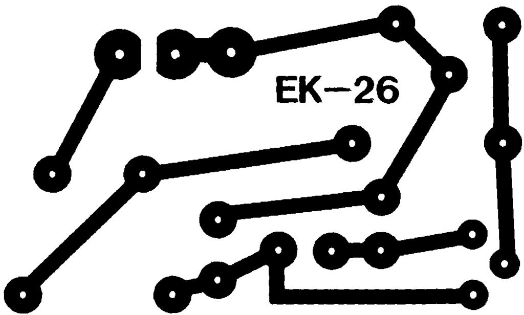
5 ASSEMBLE COMPONENTS TO THE PC BOARD P1-50kΩ Potentiometer R1-15kΩ 5% 1/4W Resistor (brown-green-orange-gold) Q1 - MPS5172 Transistor (see Figure A) L1 - Coil (see Figure B) C μF Capacitor (152) S1 - Switch B1 - Battery Snap - Install the red wire into the positive (+) hole and the black wire into the negative (--) hole. and cut off the excess leads. R2-4.7kΩ 5% 1/4W Resistor (yellow-violet-red-gold) C1-680pF Discap (681) Figure A Mount the transistor to the PC board at the location shown. Note the flat side of the transistor and the marking on the PC board. and cut off the excess leads. Figure B Find the two ends of the coil. Using a file or a razor blade, strip the enamel insulation from the wire 1/4 so the solder will make good contact with the wire. Insert the ends of the coil into the PC board. and cut off the excess leads. Flat 1/4 1/4-4-
6


7 QUIZ 1. The Metal Detector basic circuit is an. 2. The Metal Detector transmits in the radio band. 3. The frequency of the oscillator changes when brought near. 4. The LC circuit is the of the oscillator. 5. All LC circuits have a frequency. 6. An LC circuit has a coil and a. 7. An inductor can be made by winding some wire into a. 8. If part of the energy in the LC circuit in Figure 1 is fed to the emitter of Q1, the circuit will. 9. When the radio and Metal Detector oscillators are at the frequency, the radio will be quiet. 10. Iron causes the LC circuit to oscillate at a frequency. OTHER ELENCO KITS Listed below are more kits that should be interesting and fun-to-build. They all perform different functions in the field of electronics. Lie Detector Kit Model K-44 The sound will tell if you are lying. The sound gets louder the more you lie. Fun at parties! Sound Activated Switch Kit Model K-36 Clap your hands and the light comes on... clap again and off it goes. Many other uses. Complete with microphone. 0-15VDC Variable Voltage DC Power Supply Kit Model XP-15K A handy portable power supply with a variable output voltage of 15VDC. Mounted in a ventilated plastic case. Ideal for students, technicians, and hobbyists. Great for breadboarding. LED Robot Blinker Kit Model AK-400 / K-17 With the LED Robot Blinker, you will learn about free-running oscillators. You ll have fun building, displaying and learning about the LED Robot Blinker. FM Microphone Kit Model AK-710 / K-30 Transmit your voice on any FM radio. Range up to 100 feet. Learn about microphones, audio amplifiers, and RF oscillators. Christmas Tree Kit Model K-14 Produces flashing colored LEDs and three popular Christmas melodies! Two IC AM Radio Kit Model AM-780K New Design - Easy-to-build, complete radio on a single PC board. Unique design allows you to place parts over their corresponding symbol on the PC board. Teaches the basic theory of AM radio operation. Detailed instructions and illustrations make it an easy and educationally sound project. Two IC FM Radio Kit Model FM-88K The FM-88K Kit is a monophonic, two-ic, FM (frequency modulation) receiver designed to receive FM signals in the frequency range (88-108MHz). It uses electronic auto-scan to search for FM stations. This scan system is done with two button switches - one switch scans up, the other resets to the start of the tuning position. Answers: 1. oscillator; 2. AM; 3. metal; 4. heart; 5. resonance; 6. capacitor; 7. coil; 8. oscillate; 9. same; 10. lower -6-
8 ELENCO 150 Carpenter Avenue Wheeling, IL (847) Website:
TELEPHONE BUG KIT MODEL K-35. Assembly and Instruction Manual
 TELEPHONE BUG KIT MODEL K-35 Assembly and Instruction Manual Elenco Electronics, Inc. Copyright 2010, 1989 by Elenco Electronics, Inc. All rights reserved. Revised 2010 REV-L 753235 No part of this book
LED ROBOT BLINKER KIT
 LED ROBOT BLINKER KIT MODEL K-17 Assembly and Instruction Manual ELENCO Copyright 2016, 1998 by ELENCO Electronics, Inc. All rights reserved. Revised 2013 REV-P 753217 No part of this book shall be reproduced
SPACE WAR GUN KIT MODEL K-10. Assembly and Instruction Manual. Elenco Electronics, Inc.
 SPACE WAR GUN KIT MODEL K-10 Assembly and Instruction Manual Elenco Electronics, Inc. Copyright 1989 Elenco Electronics, Inc. Revised 2001 REV-H 753210A PARTS LIST Contact Elenco Electronics (address/phone/e-mail
LED ROBOT BLINKER KIT
 LED ROBOT BLINKER KIT MODEL K-17 Assembly and Instruction Manual Elenco Electronics, Inc. Copyright 1989, 1998 Elenco Electronics, Inc. Revised 2001 REV-J 753217 PARTS LIST If any parts are missing or
AC/DC POWER SUPPLY KIT
 AC/DC POWER SUPPLY KIT MODEL K-11 Assembly and Instruction Manual ELENCO Copyright 2016, 1989 by ELENCO All rights reserved. Revised 2016 REV-O 753211 No part of this book shall be reproduced by any means;
YAP BOX KIT MODEL K-22A YAP BOX SIX EXCITING SOUNDS. Assembly and Instruction Manual
 YAP BOX KIT MODEL K-22A YAP BOX SIX EXCITING SOUNDS Assembly and Instruction Manual Elenco Electronics, Inc. Copyright 2009, 1989 by Elenco Electronics, Inc. All rights reserved. Revised 2009 REV-H 753222
DIODE / TRANSISTOR TESTER KIT
 DIODE / TRANSISTOR TESTER KIT MODEL DT-100K 99 Washington Street Melrose, MA 02176 Phone 781-665-1400 Toll Free 1-800-517-8431 Visit us at www.testequipmentdepot.com Assembly and Instruction Manual Elenco
FUNCTION GENERATOR KIT
 FUNCTION GENERATOR KIT MODEL FG-500K Assembly and Instruction Manual Elenco Electronics, Inc. Copyright 2005 by Elenco Electronics, Inc. All rights reserved. Revised 2005 REV-B 753069 No part of this book
LOGIC PROBE KIT MODEL LP-525K. Assembly and Instruction Manual ELENCO
 LOGIC PROBE KIT MODEL LP-525K Assembly and Instruction Manual ELENCO Copyright 2013, 1994 by Elenco Electronics, Inc. All rights reserved. Revised 2013 REV-J 753241 No part of this book shall be reproduced
NERVE TESTER KIT MODEL K-20. Assembly and Instruction Manual. Elenco Electronics, Inc.
 NERVE TESTER KIT MODEL K-20 Assembly and Instruction Manual Elenco Electronics, Inc. Copyright 1989 Elenco Electronics, Inc. Revised 2002 REV-E 753220 PARTS LIST If you are a student, and any parts are
DIODE / TRANSISTOR TESTER KIT
 DIODE / TRANSISTOR TESTER KIT MODEL DT-100K Assembly and Instruction Manual Elenco Electronics, Inc. Copyright 1988 Elenco Electronics, Inc. Revised 2002 REV-K 753110 DT-100 PARTS LIST If you are a student,
AM RADIO KIT MODEL AM-780K. Assembly and Instruction Manual ELENCO
 AM-780K_REV-K_050416.qxp_AM-780K_REV-K_050416 5/10/16 8:13 AM Page 1 AM RADIO KIT MODEL AM-780K Assembly and Instruction Manual ELENCO Copyright 2016, 1999 by Elenco Electronics, Inc. All rights reserved.
Solder Practice Kit MODEL AK-100. Elenco Electronics, Inc. Lesson Manual. Elenco Electronics, Inc.
 Solder Practice Kit MODEL AK-100 Elenco Electronics, Inc. 150 W. Carpenter Avenue Wheeling, IL 60090 (847) 541-3800 http://www.elenco.com e-mail: elenco@elenco.com Lesson Manual Elenco Electronics, Inc.
AUTO-SCAN FM RADIO KIT
 FM-88K 071210.qxp_FM-88K 060810 12/29/15 10:05 AM Page 1 AUTO-SCAN FM RADIO KIT MODEL FM-88K Assembly and Instruction Manual ELENCO Copyright 2016, 2011 by ELENCO All rights reserved. No part of this book
AM RADIO KIT MODEL AM-780K. Assembly and Instruction Manual
 AM RADIO KIT MODEL AM-780K Assembly and Instruction Manual Elenco Electronics, Inc. Copyright 2007, 1999 by Elenco Electronics, Inc. All rights reserved. Revised 2007 REV-F 753108 No part of this book
SMT - TRAINING COURSE
 SMT - TRAINING COURSE MODEL SM-200K Surface Mount Technology Kit Assembly and Instruction Manual ELENCO Copyright 2016, 2000 ELENCO Electronics, Inc. Revised 2015 REV-P 753200 No part of this book shall
FUNCTION GENERATOR KIT
 FUNCTION GENERATOR KIT MODEL FG-500K Assembly and Instruction Manual ELENCO Copyright 2016 by Elenco Electronics, Inc. All rights reserved. Revised 2016 REV-H 753069 No part of this book shall be reproduced
AUTO-SCAN FM RADIO KIT
 AUTO-SCAN FM RADIO KIT MODEL FM-88K ELENCO 150 Carpenter Avenue Wheeling, IL 0090 (8) 51-800 Website: www.elenco.com e-mail: elenco@elenco.com To see our complete line of Educational Products go to WWW.ELENCO.COM
SOLDER PRACTICE KIT MODEL SP-3B. Assembly and Instruction Manual ELENCO
 SOLDER PRACTICE KIT MODEL SP-3B Assembly and Instruction Manual ELENCO Copyright 2017, 2001 by Elenco Electronics, Inc. All rights reserved. Revised 2012 REV-K No part of this book shall be reproduced
SOLDER PRACTICE KIT MODEL SP-1A
 99 Washington Street Melrose, MA 02176 Phone 781-665-1400 Toll Free 1-800-517-8431 Visit us at www.testequipmentdepot.com SOLDER PRACTICE KIT MODEL SP-1A Assembly and Instruction Manual Elenco Electronics,
FUNCTION GENERATOR KIT
 FUNCTION GENERATOR KIT MODEL FG-600K Assembly and Instruction Manual ELENCO Copyright 2016, 1999 by ELENCO All rights reserved. Revised 2016 REV-G 753033 No part of this book shall be reproduced by any
SOLDER PRACTICE KIT MODEL SP-1A. Assembly and Instruction Manual
 SOLDER PRACTICE KIT MODEL SP-1A Assembly and Instruction Manual Copyright 2018, 1994 by ELENCO Electronics, Inc. All rights reserved. Revised 2018 REV-V No part of this book shall be reproduced by any
SOLDER PRACTICE KIT MODEL SP-3B. Assembly and Instruction Manual
 SOLDER PRACTICE KIT MODEL SP-3B 99 Washington Street Melrose, MA 02176 Phone 781-665-1400 Toll Free 1-800-517-8431 Visit us at www.testequipmentdepot.com Assembly and Instruction Manual Elenco Electronics,
POWER SUPPLY KIT MODEL XP-720K. Assembly Manual ELENCO
 POWER SUPPLY KIT MODEL XP-720K Assembly Manual ELENCO Copyright 2012, 1998 by ELENCO All rights reserved. Revised 2012 REV-G 753269 No part of this book shall be reproduced by any means; electronic, photocopying,
DIGITAL MULTIMETER KIT
 DIGITAL MULTIMETER KIT MODEL M-1007K Assembly and Instruction Manual Elenco Electronics, Inc. Copyright 2008 by Elenco Electronics, Inc. All rights reserved. 753096 No part of this book shall be reproduced
AM/FM RADIO KIT MODEL AM/FM-108CK SUPERHET RADIO CONTAINS TWO SEPARATE AUDIO SYSTEMS: IC AND TRANSISTOR. Assembly and Instruction Manual ELENCO
 AM/FM RADIO KIT MODEL AM/FM-108CK SUPERHET RADIO CONTAINS TWO SEPARATE AUDIO SYSTEMS: IC AND TRANSISTOR Assembly and Instruction Manual ELENCO Copyright 2012 by ELENCO All rights reserved. 753510 No part
DIGITAL MULTIMETER KIT
 DIGITAL MULTIMETER KIT MODEL M-1008K Assembly and Instruction Manual ELENCO Copyright 2012 by ELENCO All rights reserved. 753014 No part of this book shall be reproduced by any means; electronic, photocopying,
MINI FM PHONE TRANSMITTER KIT
 MINI FM PHONE TRANSMITTER KIT Description: This is a subminiature FM telephone transmitter capable of transmitting both sides of a telephone conversation to most any FM receiver up to 1/4 mile away. When
DIGITAL MULTIMETER KIT
 DIGITAL MULTIMETER KIT MODEL M-2666K WIDE RANGE DIGITAL MULTIMETER WITH CAPACITANCE AND TRANSISTOR TESTING FEATURES Assembly and Instruction Manual ELENCO Copyright 2010 by ELENCO All rights reserved.
Technical Specifications - Characteristics
 Watt FM TRANSMITTER General Description This is a small but quite powerful FM transmitter having three RF stages incorporating an audio preamplifier for better modulation. t has an output power of 4 Watts
MOTION DETECTOR KIT MODEL AK-510
 MOTION DETECTOR KIT MODEL AK-510 Assembly and Instruction Manual PARTS LIST RESISTORS QTY SYMBOL DESCRIPTION COLOR CODE PART # 1 R16 300Ω 5% 1/4W orange-black-brown-gold 133000 1 R15 5.6kΩ 5% 1/4W green-blue-red-gold
AM/FM RADIO KIT MODEL AM/FM-108K INTEGRAL CIRCUIT, 9 TRANSISTORS, 4 DIODES. Assembly and Instruction Manual
 AM/FM RADIO KIT MODEL AM/FM-108K INTEGRAL CIRCUIT, 9 TRANSISTORS, 4 DIODES Assembly and Instruction Manual Elenco Electronics, Inc. Copyright 2009, 1989 by Elenco Electronics, Inc. All rights reserved.
CI-22. BASIC ELECTRONIC EXPERIMENTS with computer interface. Experiments PC1-PC8. Sample Controls Display. Instruction Manual
 CI-22 BASIC ELECTRONIC EXPERIMENTS with computer interface Experiments PC1-PC8 Sample Controls Display See these Oscilloscope Signals See these Spectrum Analyzer Signals Instruction Manual Elenco Electronics,
Cornerstone Electronics Technology and Robotics I Week 19 Soldering Tutorial
 Cornerstone Electronics Technology and Robotics I Week 19 Soldering Tutorial Administration: o Prayer o Turn in quiz o Using fixed resistors design and build a voltage divider divides 5 volts in half.
AM/FM RADIO KIT MODEL AM/FM-108K INTEGRAL CIRCUIT, 9 TRANSISTORS, 4 DIODES. Assembly and Instruction Manual
 AM/FM RADIO KIT MODEL AM/FM-108K INTEGRAL CIRCUIT, 9 TRANSISTORS, 4 DIODES Assembly and Instruction Manual TM Elenco Electronics, Inc. Copyright 2003, 1989 by Elenco TM Electronics, Inc. All rights reserved.
DIGITAL MULTIMETER KIT
 DIGITAL MULTIMETER KIT MODEL M-2666K WIDE RANGE DIGITAL MULTIMETER WITH CAPACITANCE AND TRANSISTOR TESTING FEATURES Assembly and Instruction Manual TM Elenco Electronics, Inc. Copyright 2003 by Elenco
Blue Ring Tester Kit Assembly & User Manual
 Blue Ring Tester Kit Assembly & User Manual Alltronics LLC/AnaTek Instruments 2761 Scott Blvd, Santa Clara, CA, 95050, USA March 2015 Edition Tel: 408-778-3868, Fax: 408-778-2558, E mail : tech@alltronics.com
Metal Detector. Student Lab Guide. Engineering Teaching Laboratory. Lab Partner(s)
") Metal Detector Student Lab Guide Engineering Teaching Laboratory Name Date Lab Partner(s) NEW TERMS Electric Circuit: Electric circuits are paths for transmitting electric current, or moving electricity.
Metal Detector Student Lab Guide Engineering Teaching Laboratory Name Date Lab Partner(s) NEW TERMS Electric Circuit: Electric circuits are paths for transmitting electric current, or moving electricity.
Building the Sawdust Regenerative Receiver
 Building the Sawdust Regenerative Receiver Introduction The Sawdust is a super regenerative receiver using the basic Armstrong design architecture. The receiver uses one toroidal transformer to provide
DIGITAL / ANALOG TRAINER
 DIGITAL / ANALOG TRAINER MODEL XK-700K A COMPLETE MINI-LAB FOR BUILDING, TESTING AND PROTOTYPING ANALOG AND DIGITAL CIRCUITS Tools and meter shown not included. Assembly & Instruction Manual ELENCO Copyright
Easy Transmitter. Support ETX_REV5_Manual V2.7 Revised
 Easy Transmitter Introduction The Easy Transmitter kit from qrpkits.com provides a basic, crystal controlled transmitter with VXO tuning to provide a small tuning range around the crystal frequency. It
ArduTouch Music Synthesizer
 ArduTouch Music Synthesizer Assembly Instructions rev C Learn To Solder download for free at: http://mightyohm.com/soldercomic The following photos will show you how to solder. But feel free to download
BAT DETECTOR A project of the Service Kring JOTA-JOTI.
 Manual Bat Detector kit Page 1 of 12 A project of the. Do you like the Bat Detector, do you have great ideas? Tell us, please see how on the last page. Manual Bat Detector kit... 1 Remarks... 2 Introduction...
QUASAR ELECTRONICS KIT No DRILL SPEED CONTROLLER
 QUASAR ELECTRONICS KIT No. 1074 DRILL SPEED CONTROLLER General Description If you work with an electric drill and unless you are lucky enough to own one of the most sophisticated models with speed control,
The Walford Electronics Ford Receiver Kit Project Construction Manual
 The Walford Electronics Ford Receiver Kit Project Construction Manual Walford Electronics Ford Receiver construction manual V1.5 Page 1 of 22 Introduction The Ford receiver has four stages: The first stage
BAT BEACON A project of the Service Kring JOTA-JOTI. Manual Bat Beacon kit.
 Manual Bat Beacon kit. Pagina 1 van 12 A project of the. Do you like the Bat-Beacon, do you have great ideas? Tell us, please see how on the last page. Manual Bat Beacon kit.... 1 Remarks... 2 Introduction...
THE RING RESONATOR (K-975)
") THE RING RESONATOR (K-975) OUTPUT BOOST The Ring Resonator An Octave Up Fuzz Modkitsdiy.com 9 VDC CENTER (-) ADAPTER TO AMP IN FROM GUITAR OUT Unplug when not in use to save battery life. Use these instructions
THE RING RESONATOR (K-975) OUTPUT BOOST The Ring Resonator An Octave Up Fuzz Modkitsdiy.com 9 VDC CENTER (-) ADAPTER TO AMP IN FROM GUITAR OUT Unplug when not in use to save battery life. Use these instructions
Building the Sawdust Regenerative Receiver
 Building the Sawdust Regenerative Receiver Introduction The Sawdust is a super regenerative receiver using the basic Armstrong design architecture. The receiver uses one toroidal transformer to provide
Pacific Antenna Field Strength Indicator Kit
 Pacific Antenna Field Strength Indicator Kit Description The Field Strength Indicator kit from Pacific Antenna provides a visual way to monitor the presence and relative strength RF fields through the
POWER SUPPLY MODEL XP-720. Instruction Manual ELENCO
 POWER SUPPLY MODEL XP-720 Instruction Manual ELENCO Copyright 2016, 1997 by ELENCO Electronics, Inc. All rights reserved. Revised 2016 REV-H 753270 No part of this book shall be reproduced by any means;
Read This Page First
 Read This Page First If you are reading this you know the manuals are always available at QRPKITS.com. This is version 8.0 of the manual dated 4/27/2016. There is no need to print out the whole assembly
Value Location Qty Potentiometers C1M Distortion 1 A10k Volume 1. Footswitch 3PDT SW1 1. Jacks 1/4 Mono 2 DC Power 1
 Distortion BUILD INSTRUCTIONS Thank you for your purchase of our Distortion+ kit! We have completely redesigned our entire line of kits to be the most user friendly, while still maintaining their same
1 TRANSISTOR CIRCUITS
 FM TRANSMITTERS The first group of circuits we will discuss are FM TRANSMITTERS. They can be called SPY TRANSMITTERS, FM BUGS, or a number of other interesting names. They all do the same thing. They transmit
THE TRILL TREMOLO (K-960)
") THE TRILL TREMOLO (K-60) DEPTH SPEED The Trill Tremolo Modkitsdiy.com Unplug when not in use to save battery life. TO AMP IN FROM GUITAR OUT Use these instructions to learn: How to build an effects pedal
THE TRILL TREMOLO (K-60) DEPTH SPEED The Trill Tremolo Modkitsdiy.com Unplug when not in use to save battery life. TO AMP IN FROM GUITAR OUT Use these instructions to learn: How to build an effects pedal
LED Field Strength Indicator Kit
 LED Field Strength Indicator Kit Description The Field Strength Indicator kit from Qrpkits.com provides a visual way to monitor RF fields through the brightness of an LED. It will respond to RF fields
Xylophone Teaching Notes Issue 1.3
 Teaching Notes Issue 1.3 Product information: www.kitronik.co.uk/quicklinks/2105/ TEACHER Xylophone Index of sheets Introduction Schemes of work Answers The Design Process The Design Brief Investigation
FM RADIO KIT ESSENTIAL INFORMATION. Version 2.0 GET IN TUNE WITH THIS
 ESSENTIAL INFORMATION BUILD INSTRUCTIONS CHECKING YOUR PCB & FAULT-FINDING MECHANICAL DETAILS HOW THE KIT WORKS GET IN TUNE WITH THIS FM RADIO KIT Version 2.0 Build Instructions Before you start, take
DIGITAL / ANALOG TRAINER
 DIGITAL / ANALOG TRAINER MODEL XK-150 A COMPLETE MINI-LAB FOR BUILDING, TESTING AND PROTOTYPING ANALOG AND DIGITAL CIRCUITS Instruction Manual ELENCO Copyright 2016, 1998 by ELENCO Electronics, Inc. All
Electronics Merit Badge Class 4. 12/30/2010 Electronics Merit Badge Class 4 1
 Electronics Merit Badge Class 4 12/30/2010 Electronics Merit Badge Class 4 1 Soldering Safety Note: A Soldering Iron gets hotter than 374 F. Do not touch the soldering iron s metal parts or you will receive
THE THUNDERDRIVE (K-950)
") THE THUNDERDRIVE (K-950) OUTPUT DISTORTION Unplug when not in use to save battery life. TO AMP IN The Thunderdrive Modkitsdiy.com FROM GUITAR OUT Use these instructions to learn: How to build an effects
THE THUNDERDRIVE (K-950) OUTPUT DISTORTION Unplug when not in use to save battery life. TO AMP IN The Thunderdrive Modkitsdiy.com FROM GUITAR OUT Use these instructions to learn: How to build an effects
Assembly Instructions
 Assembly Instructions For the SSQ-2F 3.1 MHz Rife Controller Board Kit v1.41 Manual v1.00 2012 by Ralph Hartwell Spectrotek Services GENERAL ASSEMBLY INSTRUCTIONS Arrange for a clean work surface with
Pacific Antenna Easy Transmitter Kit
 Pacific Antenna Easy Transmitter Kit Introduction The Easy Transmitter kit from qrpkits.com provides a crystal controlled transmitter with VXO tuning. The circuit consists of a N3904 based crystal oscillator
Musical Pencil. Tutorial modified from musical pencil/
 Musical Pencil This circuit takes advantage of the fact that graphite in pencils is a conductor, and people are also conductors. This uses a very small voltage and high resistance so that it s safe. When
DIGITAL MULTIMETER KIT MODEL M-2665K WIDE RANGE DIGITAL MULTIMETER WITH CAPACITANCE AND TRANSISTOR TESTING FEATURES
 DIGITAL MULTIMETER KIT MODEL M-2665K WIDE RANGE DIGITAL MULTIMETER WITH CAPACITANCE AND TRANSISTOR TESTING FEATURES Assembly and Instruction Manual INTRODUCTION Assembly of your M-2665 Digital Multimeter
DIGITAL MULTIMETER KIT
 DIGITAL MULTIMETER KIT MODEL M-2665K WIDE RANGE DIGITAL MULTIMETER WITH CAPACITANCE AND TRANSISTOR TESTING FEATURES Elenco Electronics, Inc. 150 W. Carpenter Avenue Wheeling, IL 60090 (847) 541-3800 http://www.elenco.com
Pacific Antenna - Easy TR Switch
 Pacific Antenna - Easy TR Switch Kit Description The Easy TR Switch is an RF sensing switch that can be used to switch an antenna between a receiver and transmitter. It also has a second switched pair
RadiØKit Μ CW HAM RADIO TRANSCEIVER KIT. Assembly and operating manual
 RadiØKit-120 20Μ CW HAM RADIO TRANSCEIVER KIT Assembly and operating manual Boreiou Ipirou 78 Kolonos Athens- Greece - 10444 Tel: 210.5150527 210.5132673 www.freebytes.com Thank you for buying RadiØKit-1,
THE AGGRESSOR (K-995)
") THE AGGRESSOR (K-99) TONE VOLUME DISTORTION MID-SHIFT SWITCH LED The Aggressor Distortion Pedal Modkitsdiy.com 9 VDC CENTER (-) ADAPTER TO AMP IN FROM GUITAR OUT Unplug when not in use to save battery
THE AGGRESSOR (K-99) TONE VOLUME DISTORTION MID-SHIFT SWITCH LED The Aggressor Distortion Pedal Modkitsdiy.com 9 VDC CENTER (-) ADAPTER TO AMP IN FROM GUITAR OUT Unplug when not in use to save battery
Pacific Antenna Easy TR Switch
 Pacific Antenna Easy TR Switch Kit Description The Easy TR Switch is an RF sensing circuit with a double pole double throw relay that can be used to automatically switch an antenna between a separate receiver
SOLDERING MANUAL A simple, yet easy to follow manual for your basic soldering needs. Copyright 2017 TortugaPro. All Rights Reserved
 A simple, yet easy to follow manual for your basic soldering needs Copyright 2017 TortugaPro. All Rights Reserved Purpose Soldering is not limited to electrical and electronics work. It is a skill that
HEAT ACTIVATED SWITCH KIT
 TEACHING RESOURCES SCHEMES OF WORK DEVELOPING A SPECIFICATION COMPONENT FACTSHEETS HOW TO SOLDER GUIDE REACT TO THE TEMPERATURE WITH THIS HEAT ACTIVATED SWITCH KIT Version 2.1 Heat Activated Switch Teaching
1. PCB and schematic
 1. PCB and schematic 2. Assembly manual WHAT'S IN THE BOX 1 x PCB tape: o 5 x jumper o 6 x resistor 1K o 12 x resistor 10K o 1 x resistor 15K o 8 x resistor 100K o 2 x resistor 47K 4 x 14p IC socket 4
Pacific Antenna Low Pass Filter Kit
 Pacific Antenna Low Pass Filter Kit Description Many basic transmitter and/or transceiver designs have minimal filtering on their output and frequently have significant harmonic content in their signals.
Building the Toothpick Audio CW Filter
 Building the Toothpick Audio CW Filter Introduction The toothpick is a simple variable bandpass audio filter designed to compliment the Splinter QRPp Trans-Receiver. The filter also contains an audio amplifier
SPECIFICATIONS: Subcarrier Frequency 5.5MHz adjustable, FM Modulated +/- 50KHz. 2nd 11MHz >40dB down from 5.5MHz
 Mini-kits AUDIO / SUBCARRIER KIT EME75 Version4 SPECIFICATIONS: Subcarrier Frequency 5.5MHz adjustable, FM Modulated +/- 50KHz Subcarrier Output 1.5v p-p Output @ 5.5MHz DESCRIPTION & FEATURES: The Notes
Name My end of year 8 Target = Teacher. OLSJ Design & Technology Electronic Products. Overall Progress Effort Rating ABCDEFG.
 Name My end of year 8 Target = Teacher OLSJ Design & Technology Electronic Products Week 1 2 3 4 5 6 7 Lesson Objectives What will you learn about today? 1. Circuit Symbols and circuit diagram 2. Drilling
No.01 Transistor Tester
 Blocks used Tester Circuits No.01 Transistor Tester Electronic components may break down if used or connected improperly. Let s start with a simple tester circuit project designed to teach you how to handle
Any Questions? Contact us or BSA Atomic Blinkie
 BSA Atomic Blinkie The heart of this blinkie is a tiny electronic chip embedded in each of the three LEDs. When power is applied, the chip tells the LED to turn on and off, or fade different colors By
Introduction. Inductors in AC Circuits.
 Module 3 AC Theory What you ll learn in Module 3. Section 3.1 Electromagnetic Induction. Magnetic Fields around Conductors. The Solenoid. Section 3.2 Inductance & Back e.m.f. The Unit of Inductance. Factors
Build this Direct Digital Synthesizer "Development Kit" By: Diz Gentzow, W8DIZ
 Build this Direct Digital Synthesizer "Development Kit" By: Diz Gentzow, W8DIZ A great tutorial for adding a keypad to the DDS Kit by Bruce, W8BH This manual has been prepared to be read directly on screen.
Cricket 80a Assembly Manual v Copyright David Cripe NM0S The 4 State QRP Group
 Cricket 80a Assembly Manual v. 1.0 Copyright 2017 David Cripe NM0S The 4 State QRP Group Introduction Thank you for purchasing a CRICKET 80a Transceiver. We hope you will enjoy building it and find it
Introduction 1. Download socket (the cable plugs in here so that the GENIE microcontroller can talk to the computer)
") Introduction 1 Welcome to the magical world of GENIE! The project board is ideal when you want to add intelligence to other design or electronics projects. Simply wire up your inputs and outputs and away
Introduction 1 Welcome to the magical world of GENIE! The project board is ideal when you want to add intelligence to other design or electronics projects. Simply wire up your inputs and outputs and away
IR add-on module circuit board assembly - Jeffrey La Favre January 27, 2015
 IR add-on module circuit board assembly - Jeffrey La Favre January 27, 2015 1 2 For the main circuits of the line following robot you soldered electronic components on a printed circuit board (PCB). The
HW-8-TR V3 PARTS LIST
 HW-8-TR V3 PARTS LIST Qty Ref Description Markings 4C2 C3 C4 C5 Capacitor Disc.1ls.1uF 104 1 C1 Capacitor Disc.2ls.1uF 100V 104 1 QSKMOD-C92 Capacitor Electrolytic 1uF 50V 1 QSKMOD Capacitor Mylar.47uF
Homebrew and Experimenters Group HF Inductance Bridge (Compiled by VK2TOX)
") Homebrew and Experimenters Group HF Inductance Bridge (Compiled by VK2TOX) There are a number of ways to measure inductances used in construction of RF equipment. One of the most versatile ways is with
Homebrew and Experimenters Group HF Inductance Bridge (Compiled by VK2TOX) There are a number of ways to measure inductances used in construction of RF equipment. One of the most versatile ways is with
Find a place where you can work through completion, without disturbing your
 Scan by Manual Manor ARIES SYSTEM 300 MUSIC SYNTHESIZER Page I of 4 MODULE AR-334 SEQUENCER ASSEMBLY INSTRUCTIONS It is recommended that you do the following before you proceed: Find a place where you
ELECTRICAL CONNECTIONS
 ELECTRICAL CONNECTIONS Lesson 13 EET 150 Electrical Connections Learning Objectives In this lesson you will: see different methods of making electrical connections. learn a procedure for making soldered
Hendricks QRP Kits The Twofer Rev
 Hendricks QRP Kits The Twofer Rev 1 11-15-06 1. Description The Twofer is a classic QRP transmitter that s easy to assemble and operate. It uses a JFET VXO (variable crystal oscillator), driver stage and
MICROGRANNY v2.1 - Assembly Guide
 last update: 9. 5. 2017 MICROGRANNY v2.1 - Assembly Guide bastl-instruments.com INTRODUCTION Welcome to the assembly guide for the MicroGranny kit. MicroGranny is a monophonic granular sampler by Bastl
Patton Robotics, LLC.
 Patton Robotics LLC Patton Robotics T3 Motherboard Assembly Instructions Version 1.1 Patton Robotics, LLC. 61 Hagan Drive New Hope, PA 18938 Phone: 609-977-5525 Email: pattonrobotics@gmail.com Copyright
Programmable Timer Teaching Notes Issue 1.2
 Teaching Notes Issue 1.2 Product information: www.kitronik.co.uk/quicklinks/2121/ TEACHER Programmable Timer Index of sheets Introduction Schemes of work Answers The Design Process The Design Brief Investigation
Value Location Qty Transistors 2N5485 Q1, Q2, 4 Q3, Q4 2N5087 Q5 1. Trim Pots 250k VTRIM 1. Potentiometers C500k Speed 1. Toggle Switch On/On Vibe 1
 P-90 BUILD INSTRUCTIONS Thank you for your purchase of our P-90 kit! We have completely redesigned our entire line of kits to be the most user friendly, while still maintaining their same great sound!
Build. WILLIAM SHEETS, K2MQJ and RUDOLF F. GRAF, KA2CWL. Sniff out metallic contraband with this hand-held device.
 Build The Frisker Gernsback Publishing, reproduce for personal use only As you probably know, recent events have made us all more security conscious. It is now common to require those entering public and
Assembly Instructions
 Assembly Instructions for the PA3 v2.0 Amplifier Kit PA3 Amplifier shown mounted on HS2 Heat Sink (The HS2 shown here is not included with this kit.) 27 February 2016 2013-2016 by Ralph Hartwell Spectrotek
Ozark Patrol Assembly Manual
 Ozark Patrol Assembly Manual Copyright 2014 David Cripe NM0S The 4 State QRP Group Thank you for purchasing a Ozark Patrol kit. We hope you will enjoy building it and and find it a fun addition to your
CHAPTER 3 PROJECT METHODOLOGY
 CHAPTER 3 PROJECT METHODOLOGY 3.1 Introduction This chapter will cover the details explanation of methodology that is being used to make this project complete and working well. Many methodology or findings
HANDS-ON LAB INSTRUCTION SHEET MODULE 3 CAPACITORS, TIME CONSTANTS AND TRANSISTOR GAIN
 HANDS-ON LAB INSTRUCTION SHEET MODULE 3 CAPACITORS, TIME CONSTANTS AND TRANSISTOR GAIN NOTES: 1) To conserve the life of the Multimeter s 9 volt battery, be sure to turn the meter off if not in use for
THE STEP LADDER (K-978)
") THE STEP LADDER (K-978) Footswitch True-bypass = 0 db OUTPUT INPUT Ground shunt switching on the input jack keeps the amp quiet when unplugged from the Step Ladder. Attenuator Pot Full clockwise = 0 db
THE STEP LADDER (K-978) Footswitch True-bypass = 0 db OUTPUT INPUT Ground shunt switching on the input jack keeps the amp quiet when unplugged from the Step Ladder. Attenuator Pot Full clockwise = 0 db
Any Questions? Contact us or Alligator Blinkie
 Alligator Blinkie The heart of this blinkie is a 12F1822 PIC produced by a company called Microchip. A PIC is a tiny, yet surprisingly powerful little computer. By itself, it can t do much it needs someway
SoftRock v5.0 Builder s Notes. December 12, Building a QSD Kit
 SoftRock v5.0 Builder s Notes December 12, 2005 Building a QSD Kit Be sure to use a grounded tip soldering iron in building the QSD board. The soldering iron needs to have a small tip, (0.05-0.1 inch diameter),