Name My end of year 8 Target = Teacher. OLSJ Design & Technology Electronic Products. Overall Progress Effort Rating ABCDEFG.
|
|
|
- Joy Carr
- 6 years ago
- Views:
Transcription

1 Name My end of year 8 Target = Teacher OLSJ Design & Technology Electronic Products Week Lesson Objectives What will you learn about today? 1. Circuit Symbols and circuit diagram 2. Drilling and soldering Push Switch to wire 1. The diode, it s purpose and how to identify it. 2. Resistors, values, colour bands, how to read them. 1. Capacitors Their purpose, types, how to identify 2. Switches Types of switches and their uses in electronic products timer Integrated Circuits Pins/ 2. To learn about soldering I.C Sockets to PCB 1. To learn about how output components switch on and off by a 555 timer 2. To learn about quality assurance in project work 1. To learn about testing a completed circuit 2. To Learn about the Photo Etching method for making a PCB 1. Learn how to use the vacuum forming process to make a case 2. How to assemble a product and add decals 8 1. End of Module Assessment 2. Review Project Plan / How did you do? Overall Progress Effort Rating ABCDEFG Overall Effort A B C D E F G Homework ABCDEFG Organisation A B C D E F G Overall % CWL Awarded
2 4 CBA 5CBA 6CBA


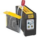
3 Preparing the soldering iron: Place the soldering iron in its stand and plug in. The iron will take a few minutes to reach its operating temperature of about C. Name the 6 items from the tool Cupboard Dampen the sponge in the stand. The best way to do this is to lift it out the stand and hold it under a tap for a moment, then squeeze to remove water. It should be, not dripping wet. Wait a few minutes for the soldering iron to warm up. You can check if it is ready by trying to a little solder on the. Wipe the tip of the iron on the damp sponge. This will clean the tip. Melt a little solder on the tip of the iron. This is called and it will help the to flow from the iron's tip to the. It only needs to be done when you in the iron, and occasionally while soldering if you need to the tip clean on the. Word Bank 400 damp excess melt tinning heat plug Joint Wipe sponge cold tip 4 CBA 5CBA 6CBA


4 Hold the soldering iron like a pen, near the base of the handle. Imagine you are going to write your name! Remember to never touch the hot element or tip. Touch the soldering iron onto the joint to be made. Make sure it touches both the component lead and the track. Hold the tip there for a few seconds and... Feed a little solder onto the joint. It should flow smoothly onto the lead and track to form a volcano shape as shown in the diagram. Apply the solder to the joint, not the iron. The smoke is the acid from the flux inside the solder wire Remove the solder, then the iron, while keeping the joint still. Allow the joint a few seconds to cool before you move the circuit board. If you burn your finger then put it under cold running water immediately Inspect the joint closely. It should look shiny and have a 'volcano' shape. If not, you will need to reheat it and feed in a little more solder. This time ensure that both the lead and track are heated fully before applying solder Component Soldering : How do you hold a soldering iron? How long do you hold the iron onto the joint before you add solder? What shape should the soldered joint be? Where does the smoke come from? What should you wear to protect the smoke from going in your eyes? What do you do if the soldered joint is not the correct shape? What should you do if you burn your finger? Label the diagram 4 CBA 5CBA 6CBA
5 The Diode A diode allows current to flow through it in direction. Current can only flow through it from the to the. A diode prevents any voltage caused by putting the in backwards. Symbol Cathode Anode Silver Band Anode one batteries cathode reverse negative Circuit A Circuit B In which circuit would the bulb light up Circuit A Circuit B Label up the legs on real life picture of the Diode Anode Cathode Summary Questions 1.What is the name of the negative terminal of a diode? 2 Give one characteristic of a diode 3. How can you tell the positive end of a diode? 4.Redraw the real life picture and the circuit symbol for a diode 5. What is a diode used for in an electronic circuit? 4 C B A 5 C B A 6 C B A
6 First band = Brown = 1 Second band = Grey = 8 Third band = Brown = One zero Value of resistor = 180 ohms First band = Brown = 1 Second band = Black = 0 Third band = Green = 6 zeros Value of resistor = 1,0, Million Ohms ( 1M ohms) 4CBA 3 correct / good attempt) 5CBA All Values with symbols 6CBA All values and simplify using prefix ( K, M)
7 4CBA (Good attempt requiring some assistance) 5CBA (Good explanations / largely correct) 6CBA (Clear and confident)
8 Capacitors store charge / voltage. The two types of capacitors you have used in your circuit are the and the Symbol for a polarised or electrolytic capacitor CAPACITORS Electric, electrolytic, non-electric, non-electrolytic Cross-out the wrong answer in the statements below An electrolytic capacitor is also known as a polarised/non-polarised capacitor The long lead (leg) of a polarised capacitor is called the cathode/anode or the positive/negative lead The short lead (leg) of a polarised capacitor is called the cathode/anode or the positive/negative lead For quality assurance purposes, a black sleeve is placed on the cathode/anode and a red sleeve on the anode/cathode. Label the anode and the Real life picture for a cathode on the real life polarised or electrolytic capacitor picture electrolytic capacitor The unit for measuring capacitance is (a) current (b) volts (c) ohms One Farad (1F) = (a) 100 (b) 1 thousand (c) 1 million Symbol for Non-polarised or non-electrolytic capacitor Name three other components you have used in your circuit which are polarised.,, and. What is the difference between the symbol of a polarised and non-polarised capacitor? Redraw the symbols for both a polarised capacitor and a battery. Clearly show the difference between them Battery microfarads (µf) Real Life picture of a Nonpolarised or nonelectrolytic capacitor Polarised capacitor Working Level:- 4A Required significant help to complete; 5B Largely completed following teachers explanation; 6C Confidently completed with good responses
9 Year 8 SWITCHES A switch will either stop or change the direction of current flowing in a circuit. When switches are used to control current flowing in circuits they can be made to make or break a path. Instructions: You are the now the Electronics Engineer! 1. You need to design a circuit that will turn a light on and off in the hallway of a new office building. 2. Build a working circuit with just a battery and a bulb. Draw battery symbol Circuit Design 1. Identify and match the switches with the symbols. (ONE HAS BEEN DONE FOR YOU) Name of switch Symbol of Switch Picture of Switch Description Draw a bulb symbol A B C red black 3. Next, add a switch in such a way that a switch turns can be included to turn the bulb on and off. Draw a Toggle switch symbol Circuit design with switch included D E Single pole single throw toggle switch (SPST switch) Push-to-Break (PTB switch) Single pole double throw micro switch (DPST switch) Double pole double throw toggle switch (DPDT switch) Double pole double throw toggle switch (DPDT switch) Push-to-Make (PTM switch) 4. Name some electronic products that use Push to make switches that could be found at school / home How well did you do? 4 CBA 5CBA 6CBA

10 Year 8 4 CBA 5CBA 6CBA
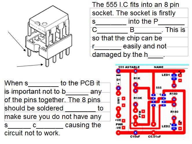
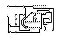
11 P Year 8 S P H P P T T P B I Label Each part of the diagram above using the correct terms below:- PCB Board, Heads LED, Tails LED, Pin 1, Negative Rail, Timing Components R1, R2, C1, Input Switch, Positive Rail Battery Snap, Strain Holes, Track,Pad, Pin 3 Output N L 4CBA (Good attempt requiring some assistance) 5CBA (Good / largely correct) 6CBA (Clear and confident)
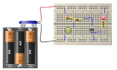
12 Year 8 Output Components- Connecting LED s to the Circuit When the toggle switch is open there is current flowing in the circuit and both LED s will be When the output pin of the 555 timer is then LED is turned When the output pin of the 555 timer is then LED is turned On your circuit board :- LED#1 should be attached to the top / bottom of the PCB LED#2 should be attached to the 555 Astable Flip Flop LED#1 PTM Toggle Switch Wire Wire On your circuit board :- The PTM switch is a P t m. When it is pressed the flashing begins. When it is r then the flashing stops and only one LED will be lit. top / bottom of the PCB LED#2 Battery Clip Battery Clip The toggle switch should be left as a loop to make sure it is always switched on 4CBA (Good attempt requiring some assistance) 5CBA (Good / largely correct) 6CBA (Clear and confident)
13 Year 8 Name of Component 1.. Component Symbol Component Drawing Component Position in Circuit CIRCUIT DIAGRAM Identify and label all the electronic components shown in all columns. (ONE HAS BEEN DONE FOR YOU) PCB Non-Polarised Capacitor. 9.. Battery, Toggle switch, Diode, Resistor, Light Emitting Diode, 555 Integrated Circuit (IC), Polarised Capacitor, Non-Polarised Capacitor, Push-To-Make Switch 4 CBA 5CBA 6CBA
 PTM Toggle Switch")
 Colour = 4 C B A 5 C B A 6 C B A")

14 Quality Assurance Testing Your Circuit Year Astable Flip Flop LED#1 (top) PTM Toggle Switch Wire TEST #1 100 presses Total LED #1 (top) Colour = LED #2 (bottom) Colour = 4 C B A 5 C B A 6 C B A Battery LED#2 (bottom) Clip Battery Clip Failure Number After X presses Test number 1 2 Pass / Fail
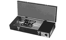

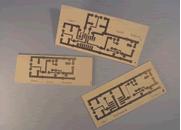

15 Manufacture of Printed Circuit Boards OLSJ Design & Technology Electronic Products PCB Manufacturing Process CBA 5CBA 6CBA


16 PVC mould Year 8 Label up the parts of the case in the correct order Which casing??? Face book Like Dislike Acrylic top fascia Acrylic back Right or Wrong Measure the dimensions of the fascia (Use mm ) Heads or Tails What made you choose the design? Label the Assembly A= LED 1 B= LED2 C= Securing hole D= Push Switch hole What other designs could be used? 4 CBA 5CBA 6CBA
17 CIRCUIT DIAGRAM PRINTED CIRCUIT BOARD (PCB) What is the purpose of a circuit diagram? How can drawing on a computer help to draw circuit diagrams? Explain what the following parts of the PCB are for Pad Tracks Text Was your soldering Poor / Good / Excellent Why? 4 C B A (Good attempt requiring some assistance) 5 C B A (Good / largely correct) 6 C B A (Clear and confident)
18 START Heads or Tails Week Drill Printed Circuit Board Record of Progress X 8 Pupil Feedback Did you complete your project ahead of schedule? Solder the Push to Make switch to wires Populate with components Test Electronics Circuit works Manufacture Casing (vacuum former) Assemble circuit into case Fit the acrylic top and design back Add graphics decals / stickers Final Testing Finish X Which was your favourite part of the project? Which was your least favourite part of the project? How could this project be improved next time? 4 C B A (Good attempt requiring some assistance) 5 C B A (Good attempt / largely correct) 6 C B A (Clear and confident answers )
19 Use the boxes to draw 3 separate views of your finished project. Use a ruler, pencil, colour to improve the quality of your drawing. Label the LED s and the Push switch on one of your drawings 4 C B A (Good attempt requiring some assistance) 5 C B A (Good attempt / largely correct) 6 C B A (Clear and confident answers )
20 Mr Hodgson s Ultimate 555 timer Word search Extension Work Can you find as many words associated with the 555 timer circuit in the grid? The winner will receive my special prize!!!!!


21 Mr Hodgson s 555 Timer Crossword Extension Work
22 Mr Hodgson s 555 Timer Hangman Extension Work Choose words from the 3 columns and play hangman in the box with your neighbouring pupil. First to 5 correct words wins!!!!!!!!!!!
23 Heads or Tails Assessment of Making Name Follow Me Stage Description of Task Soldered across? Features of component Your Comment on soldering/ quality / what you understand Target Week to complete Actual Week Completed? 1 Drill 1mm(x32) and 2mm(x10) 1 2 PUSH TO MAKE SWITCH PTM 1 3 Diode D1 Silver band is Cathode 2 4 Resistor 1K R1K Brown, Black, Red, Gold 2 5 Resistor 10K R10K Brown, Black, Orange, Gold 2 6 Capacitor 10uF C10uF Long (+VE) and short leg (-VE) 3 7 Switch SW1 SW1 Yellow multi core wire (30cm) 3 8 PTM Switch PTM Yellow multi core wire (15cm) 3 9 Capacitor 0.01uF (10nF) C0.01uF Orange circular shape. Legs equal length. 104 written on 10 8 Pin Socket 555 Notch with number 8 to top 4 11 Resistor R180 R180 Brown, Grey, Brown, Gold 4 12 Resistor R180 R180 Brown, Grey, Brown, Gold 4 13 LED #1 LED1 Long leg = red, short leg = black 5 14 LED #2 LED2 Long leg = red, short leg = black 5 15 BATTERY CLIP PWR Stitched through strain holes 5 16 INSERT 555 CHIP Pin 1 has a dimple (top left) 6 17 TESTING Battery press switch to flash 6 18 Assemble in case PVC Mould and acrylic case 7 3
Any Questions? Contact us or Alligator Blinkie
 Alligator Blinkie The heart of this blinkie is a 12F1822 PIC produced by a company called Microchip. A PIC is a tiny, yet surprisingly powerful little computer. By itself, it can t do much it needs someway
Introduction 1. Download socket (the cable plugs in here so that the GENIE microcontroller can talk to the computer)
") Introduction 1 Welcome to the magical world of GENIE! The project board is ideal when you want to add intelligence to other design or electronics projects. Simply wire up your inputs and outputs and away
Introduction 1 Welcome to the magical world of GENIE! The project board is ideal when you want to add intelligence to other design or electronics projects. Simply wire up your inputs and outputs and away
DIODE / TRANSISTOR TESTER KIT
 DIODE / TRANSISTOR TESTER KIT MODEL DT-100K Assembly and Instruction Manual Elenco Electronics, Inc. Copyright 1988 Elenco Electronics, Inc. Revised 2002 REV-K 753110 DT-100 PARTS LIST If you are a student,
Introduction. Pictures in this lab have been taken from Pre-Lab Homework
 Introduction This lab relates to material in Hecht, Chapter 18. In this lab you will explore the concepts of circuits, resistors, and capacitors, by actually building a small circuit that is yours to keep!
DIODE / TRANSISTOR TESTER KIT
 DIODE / TRANSISTOR TESTER KIT MODEL DT-100K 99 Washington Street Melrose, MA 02176 Phone 781-665-1400 Toll Free 1-800-517-8431 Visit us at www.testequipmentdepot.com Assembly and Instruction Manual Elenco
LED ROBOT BLINKER KIT
 LED ROBOT BLINKER KIT MODEL K-17 Assembly and Instruction Manual Elenco Electronics, Inc. Copyright 1989, 1998 Elenco Electronics, Inc. Revised 2001 REV-J 753217 PARTS LIST If any parts are missing or
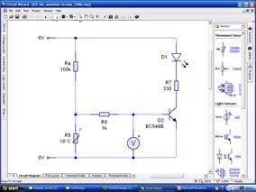
Amplifier, Product Design
 Amplifier, Product Design Choose one component from the amplifier circuit and investigate technical, theory and mathematical information related to your chosen component. This work will be completed over
Programmable Timer Teaching Notes Issue 1.2
 Teaching Notes Issue 1.2 Product information: www.kitronik.co.uk/quicklinks/2121/ TEACHER Programmable Timer Index of sheets Introduction Schemes of work Answers The Design Process The Design Brief Investigation
EASY BUILD TIMER KIT TEACHING RESOURCES. Version 2.0 LEARN ABOUT SIMPLE TIMING CIRCUITS WITH THIS
 TEACHING RESOURCES SCHEMES OF WORK DEVELOPING A SPECIFICATION COMPONENT FACTSHEETS HOW TO SOLDER GUIDE LEARN ABOUT SIMPLE TIMING CIRCUITS WITH THIS EASY BUILD TIMER KIT Version 2.0 Index of Sheets TEACHING
Electronics Merit Badge Class 4. 12/30/2010 Electronics Merit Badge Class 4 1
 Electronics Merit Badge Class 4 12/30/2010 Electronics Merit Badge Class 4 1 Soldering Safety Note: A Soldering Iron gets hotter than 374 F. Do not touch the soldering iron s metal parts or you will receive
STEADY HAND GAME WITH LATCHING LED
 ESSENTIAL INFORMATION BUILD INSTRUCTIONS CHECKING YOUR PCB & FAULT-FINDING MECHANICAL DETAILS HOW THE KIT WORKS TEST YOUR HAND-EYE COORDINATION WITH THIS STEADY HAND GAME WITH LATCHING LED Version 2.0
Lighthouse Beginner s soldering kit
 Lighthouse Beginner s soldering kit Kit contains: 1 x 220 ohm resistor (Red, Red, Black) 1 x 82k ohm resistor (Grey, Red, Orange) 2 x 220k ohm resistors (Red, Red, Yellow) 2 x Diodes 1 x Power switch 1
SPACE WAR GUN KIT MODEL K-10. Assembly and Instruction Manual. Elenco Electronics, Inc.
 SPACE WAR GUN KIT MODEL K-10 Assembly and Instruction Manual Elenco Electronics, Inc. Copyright 1989 Elenco Electronics, Inc. Revised 2001 REV-H 753210A PARTS LIST Contact Elenco Electronics (address/phone/e-mail
Gat ew ay T o S pace AS EN / AS TR Class # 07. Colorado S pace Grant Consortium
 Gat ew ay T o S pace AS EN / AS TR 2500 Class # 07 Colorado S pace Grant Consortium One Minute Reports: - Can we have two data loggers? - Do you provide us with cameras? {Hardware Checkout after proposal}
Introduction. Circuit diagram
 Introduction You must have played with a dice at some time, for example when playing Ludo or Monopoly. Dice have existed for a very long time. The first known six-sided dice were found in Iraq and were
5W Mono Amplifier Kit
 5W Mono Amplifier Kit Kit Construction Before you start assembling your kit there are a couple of important things you must do. FIRST read through these instructions entirely before you start construction
Design and Technology
 E.M.F, Voltage and P.D E.M F This stands for Electromotive Force (e.m.f) A battery provides Electromotive Force An e.m.f can make an electric current flow around a circuit E.m.f is measured in volts (v).
Micro USB Lamp Kit TEACHING RESOURCES. Version 2.1 DESIGN A STYLISH LAMP WITH THIS
 TEACHING RESOURCES SCHEMES OF WORK DEVELOPING A SPECIFICATION COMPONENT FACTSHEETS HOW TO SOLDER GUIDE DESIGN A STYLISH LAMP WITH THIS Micro USB Lamp Kit Version 2.1 Index of Sheets TEACHING RESOURCES
Lesson 2: Soldering. Goals
 Introduction: Its time to learn how to solder. So you have met all the components needed to make a DIY Gamer, now it s time to put it together. Soldering is joining the components to the printed circuit
Any Questions? Contact us or BSA Atomic Blinkie
 BSA Atomic Blinkie The heart of this blinkie is a tiny electronic chip embedded in each of the three LEDs. When power is applied, the chip tells the LED to turn on and off, or fade different colors By
Lesson 2: Soldering. Goals
 Introduction: Its time to learn how to solder. So you have met all the components needed to make a DIY Gamer, now it s time to put it together. Soldering is joining the components to the printed circuit
Solder Practice Kit MODEL AK-100. Elenco Electronics, Inc. Lesson Manual. Elenco Electronics, Inc.
 Solder Practice Kit MODEL AK-100 Elenco Electronics, Inc. 150 W. Carpenter Avenue Wheeling, IL 60090 (847) 541-3800 http://www.elenco.com e-mail: elenco@elenco.com Lesson Manual Elenco Electronics, Inc.
LED ROBOT BLINKER KIT
 LED ROBOT BLINKER KIT MODEL K-17 Assembly and Instruction Manual ELENCO Copyright 2016, 1998 by ELENCO Electronics, Inc. All rights reserved. Revised 2013 REV-P 753217 No part of this book shall be reproduced
Xylophone Teaching Notes Issue 1.3
 Teaching Notes Issue 1.3 Product information: www.kitronik.co.uk/quicklinks/2105/ TEACHER Xylophone Index of sheets Introduction Schemes of work Answers The Design Process The Design Brief Investigation
DARK ACTIVATED COLOUR CHANGING NIGHT LIGHT KIT
 TEACHING RESOURCES SCHEMES OF WORK DEVELOPING A SPECIFICATION COMPONENT FACTSHEETS HOW TO SOLDER GUIDE CREATE SOOTHING LIGHTING EFFECTS WITH THIS DARK ACTIVATED COLOUR CHANGING NIGHT LIGHT KIT Version
Experiment 2 Soldering Parallel and Series Circuits and using the Digital Multimeter
 Experiment 2 Soldering Parallel and Series Circuits and using the Digital Multimeter Introduction Soldering is the most common means of joining components to each other or to circuit boards in electronics.
Voltage Current V I. Resistors are colour-coded: the number of Ohms resistance is indicated by a series of coloured bands on the resistor.
 Introduction to Electronics Part 1: Some Basic Ideas and omponents urrent, Voltage and esistance urrent is a measure of the rate of flow of charge (unit: the Amp). Voltage is a measure of the force with
DELUXE STEREO AMPLIFIER KIT
 TEACHING RESOURCES SCHEMES OF WORK DEVELOPING A SPECIFICATION COMPONENT FACTSHEETS HOW TO SOLDER GUIDE CREATE YOUR OWN SPEAKER DOCK WITH THIS DELUXE STEREO AMPLIFIER KIT Version 2.0 Index of Sheets TEACHING
Line-Following Robot
 1 Line-Following Robot Printed Circuit Board Assembly Jeffrey La Favre October 5, 2014 After you have learned to solder, you are ready to start the assembly of your robot. The assembly will be divided
LOGIC PROBE KIT MODEL LP-525K. Assembly and Instruction Manual ELENCO
 LOGIC PROBE KIT MODEL LP-525K Assembly and Instruction Manual ELENCO Copyright 2013, 1994 by Elenco Electronics, Inc. All rights reserved. Revised 2013 REV-J 753241 No part of this book shall be reproduced
YAP BOX KIT MODEL K-22A YAP BOX SIX EXCITING SOUNDS. Assembly and Instruction Manual
 YAP BOX KIT MODEL K-22A YAP BOX SIX EXCITING SOUNDS Assembly and Instruction Manual Elenco Electronics, Inc. Copyright 2009, 1989 by Elenco Electronics, Inc. All rights reserved. Revised 2009 REV-H 753222
HEAT ACTIVATED SWITCH KIT
 TEACHING RESOURCES SCHEMES OF WORK DEVELOPING A SPECIFICATION COMPONENT FACTSHEETS HOW TO SOLDER GUIDE REACT TO THE TEMPERATURE WITH THIS HEAT ACTIVATED SWITCH KIT Version 2.1 Heat Activated Switch Teaching
Learn to Solder: Simon Says Stencil Kit Information & Instructions
 Learn to Solder: Simon Says Stencil Kit Information & Instructions This is considered an intermediate kit for people who have soldered through-hole components before and wish to learn how to reflow surface
Ultimatum Fuzz. The Ultimate experience in vintage-style octave-up fuzz
 Ultimatum Fuzz The Ultimate experience in vintage-style octave-up fuzz Contents of this document are 2015 Pedal Parts Ltd. No reproduction permitted without the express written permission of Pedal Parts
Value Location Qty Potentiometers C1M Distortion 1 A10k Volume 1. Footswitch 3PDT SW1 1. Jacks 1/4 Mono 2 DC Power 1
 Distortion BUILD INSTRUCTIONS Thank you for your purchase of our Distortion+ kit! We have completely redesigned our entire line of kits to be the most user friendly, while still maintaining their same
ELECTRONICS STARTER KIT
 ELECTRONICS STARTER KIT (MAP 474 - N02QQ) R These five small self-assembly circuits cover basic principles of electronics and can be adapted for numerous practical application. The five circuits include
Assembly instructions for the CS-1 ChemShield
 Page 1 Of 6 Assembly instructions for the CS-1 ChemShield What is S.M.D SMD=Surface mount devices, like all the components does not have leads, but gets soldered onto flat solder pads. The CS-1 assembly
BAT DETECTOR A project of the Service Kring JOTA-JOTI.
 Manual Bat Detector kit Page 1 of 12 A project of the. Do you like the Bat Detector, do you have great ideas? Tell us, please see how on the last page. Manual Bat Detector kit... 1 Remarks... 2 Introduction...
Basic Electronics Course Part 2
 Basic Electronics Course Part 2 Simple Projects using basic components Including Transistors & Pots Following are instructions to complete several electronic exercises Image 7. Components used in Part
12V Dimmer Kit, version 2
 12V Dimmer Kit, version 2 User Manual Description The 12V Dimmer Kit V2 is an especially efficient PWM (pulse-width modulation) controller for 12V loads up to 60 watts. It features a single dial control
Heartboard PCB Assembly Instructions
 Heartboard PCB Assembly Instructions Thanks for purchasing a Heartboard! These instructions will guide you through assembling and testing the Heartboard. Let s get started! Stuff you need Soldering iron
ECE 477 Digital Systems Senior Design Project. Module 11 Board Assembly and Soldering Techniques
 2011 by D. G. Meyer ECE 477 Digital Systems Senior Design Project Module 11 Board Assembly and Soldering Techniques Outline I ve got my board, now what? Which end of this thing gets hot? Flux is your friend.
Firefly Jar Learn to Solder Kit
 Firefly Jar Learn to Solder Kit Parts Tools A. Firefly Jar PCB B. 10mm Flickering LED (White or Yellow) C. Resistor D. Tilt Switch (Black or Green) E. Battery Holder F. Velcro ( Not Pictured) G. Jar (
Assembly and User Guide
 Assembly and User Guide AtariPunkr is an adjustable stepped tone generator. AtariPunkr provides hours of fun everyone! Powered by: 9V Battery Outputs: Mylar Speaker (Included) Stereo Output (3.5mm Jack)
NERVE TESTER KIT MODEL K-20. Assembly and Instruction Manual. Elenco Electronics, Inc.
 NERVE TESTER KIT MODEL K-20 Assembly and Instruction Manual Elenco Electronics, Inc. Copyright 1989 Elenco Electronics, Inc. Revised 2002 REV-E 753220 PARTS LIST If you are a student, and any parts are
TEACHING RESOURCES SCHEMES OF WORK DEVELOPING A SPECIFICATION COMPONENT FACTSHEETS HOW TO SOLDER GUIDE GET IN TUNE WITH THIS FM RADIO KIT. Version 2.
 TEACHING RESOURCES SCHEMES OF WORK DEVELOPING A SPECIFICATION COMPONENT FACTSHEETS HOW TO SOLDER GUIDE GET IN TUNE WITH THIS FM RADIO KIT Version 2.2 Index of Sheets TEACHING RESOURCES Index of Sheets
Value Location Qty Transistors 2N5485 Q1, Q2, 4 Q3, Q4 2N5087 Q5 1. Trim Pots 250k VTRIM 1. Potentiometers C500k Speed 1. Toggle Switch On/On Vibe 1
 P-90 BUILD INSTRUCTIONS Thank you for your purchase of our P-90 kit! We have completely redesigned our entire line of kits to be the most user friendly, while still maintaining their same great sound!
16 Bit Micro Experimenter Assembly and Check out Instructions
 16 Bit Micro Experimenter Assembly and Check out Instructions The kit you purchased that includes PCB, schematic, complete parts list and these assembly instructions. A top picture of the complete assembly
FUNCTION GENERATOR KIT
 FUNCTION GENERATOR KIT MODEL FG-500K Assembly and Instruction Manual Elenco Electronics, Inc. Copyright 2005 by Elenco Electronics, Inc. All rights reserved. Revised 2005 REV-B 753069 No part of this book
Pacific Antenna Easy TR Switch
 Pacific Antenna Easy TR Switch Kit Description The Easy TR Switch is an RF sensing circuit with a double pole double throw relay that can be used to automatically switch an antenna between a separate receiver
Unit 1 Electronics Name: Form:
 Unit 1 Electronics Name: Form: Electronics Electronics is the study of components and techniques used to be able to build circuits controlled by electricity. An electronic system uses discrete components.
Tek-Bot Remote Control Transmitter Board Construction
 Tek-Bot Remote Control Transmitter Board Construction Purpose This tutorial illustrates the procedure for construction of the Transmitter board for the Tek-bot. A Guide to Soldering Many of you have soldered
Temperature activated switch
 Build instructions, circuit explanation and example applications Issue 1.5 Product information: www.kitronik.co.uk/quicklinks/2113/ TEACHER Temperature activated switch Introduction About the project kit
Total solder points: Difficulty level: beginner advanced 0 TO 60 HOUR START / STOP TIMER K6200 ILLUSTRATED ASSEMBLY MANUAL
 Total solder points: 96 + 43 Difficulty level: beginner 1 2 3 4 5 advanced 0 TO 60 HOUR START / STOP TIMER K6200 Broad range mains operated start / stop timer. ILLUSTRATED ASSEMBLY MANUAL H6200IP-1 VELLEMAN
Signal Lights Demonstration Video Time Duration: - 38 sec. Use the right hand mouse button for video control.
 Tip: - Working Turntable Signals and Cabin Lights using Gold TC7.0F1 and Above Hi All, At long last I completed the project to have working signals and cabin lights on my turntable. This is a record of
tinycylon Assembly Instructions Contents Written by Dale Wheat Version August 2016 Visit dalewheat.com for the latest update!
 tinycylon Assembly Instructions Written by Dale Wheat Version 2.1 10 August 2016 Visit dalewheat.com for the latest update! Contents Assembly Instructions...1 Contents...1 Introduction...2 Quick Start
Pacific Antenna Easy SWR Indicator Kit
 Pacific Antenna Easy SWR Indicator Kit Description Monitoring the match of an antenna to your transmitter or adjusting an antenna tuner for best match requires an indicator of the reflected power as an
SOLDERING MANUAL A simple, yet easy to follow manual for your basic soldering needs. Copyright 2017 TortugaPro. All Rights Reserved
 A simple, yet easy to follow manual for your basic soldering needs Copyright 2017 TortugaPro. All Rights Reserved Purpose Soldering is not limited to electrical and electronics work. It is a skill that
THE RING RESONATOR (K-975)
") THE RING RESONATOR (K-975) OUTPUT BOOST The Ring Resonator An Octave Up Fuzz Modkitsdiy.com 9 VDC CENTER (-) ADAPTER TO AMP IN FROM GUITAR OUT Unplug when not in use to save battery life. Use these instructions
THE RING RESONATOR (K-975) OUTPUT BOOST The Ring Resonator An Octave Up Fuzz Modkitsdiy.com 9 VDC CENTER (-) ADAPTER TO AMP IN FROM GUITAR OUT Unplug when not in use to save battery life. Use these instructions
ABC V1.0 ASSEMBLY IMPORTANT!
 ABC V1.0 ASSEMBLY Before starting this kit, prepare the following tools: Soldering iron (15-20W will do), flush cutters, no.2 hex screwdriver or allen key and phillips screwdriver. Also briefly go through
THE THUNDERDRIVE (K-950)
") THE THUNDERDRIVE (K-950) OUTPUT DISTORTION Unplug when not in use to save battery life. TO AMP IN The Thunderdrive Modkitsdiy.com FROM GUITAR OUT Use these instructions to learn: How to build an effects
THE THUNDERDRIVE (K-950) OUTPUT DISTORTION Unplug when not in use to save battery life. TO AMP IN The Thunderdrive Modkitsdiy.com FROM GUITAR OUT Use these instructions to learn: How to build an effects
Electronics Merit Badge Kit Theory of Operation
 Electronics Merit Badge Kit Theory of Operation This is an explanation of how the merit badge kit functions. There are several topics worthy of discussion. These are: 1. LED operation. 2. Resistor function
AC/DC POWER SUPPLY KIT
 AC/DC POWER SUPPLY KIT MODEL K-11 Assembly and Instruction Manual ELENCO Copyright 2016, 1989 by ELENCO All rights reserved. Revised 2016 REV-O 753211 No part of this book shall be reproduced by any means;
THE STEP LADDER (K-978)
") THE STEP LADDER (K-978) Footswitch True-bypass = 0 db OUTPUT INPUT Ground shunt switching on the input jack keeps the amp quiet when unplugged from the Step Ladder. Attenuator Pot Full clockwise = 0 db
THE STEP LADDER (K-978) Footswitch True-bypass = 0 db OUTPUT INPUT Ground shunt switching on the input jack keeps the amp quiet when unplugged from the Step Ladder. Attenuator Pot Full clockwise = 0 db
BAT BEACON A project of the Service Kring JOTA-JOTI. Manual Bat Beacon kit.
 Manual Bat Beacon kit. Pagina 1 van 12 A project of the. Do you like the Bat-Beacon, do you have great ideas? Tell us, please see how on the last page. Manual Bat Beacon kit.... 1 Remarks... 2 Introduction...
Workshop Part Identification Lecture N I A G A R A C O L L E G E T E C H N O L O G Y D E P T.
 Workshop Part Identification Lecture N I A G A R A C O L L E G E T E C H N O L O G Y D E P T. Identifying Resistors Resistors can be either fixed or variable. The variable kind are called potentiometers
Cornerstone Electronics Technology and Robotics I Week 19 Soldering Tutorial
 Cornerstone Electronics Technology and Robotics I Week 19 Soldering Tutorial Administration: o Prayer o Turn in quiz o Using fixed resistors design and build a voltage divider divides 5 volts in half.
Gertboard Assembly Manual Rev 1.1
 Gertboard Assembly Manual Rev 1.1 The Gertboard is an add-on GPIO expansion board for the Raspberry Pi computer. It comes with a large variety of components, including buttons, LEDs, A/D converters, DACs,
ArduTouch Music Synthesizer
 ArduTouch Music Synthesizer Assembly Instructions rev C Learn To Solder download for free at: http://mightyohm.com/soldercomic The following photos will show you how to solder. But feel free to download
LEARN TO SOLDER CLASS PACK
 TEACHING RESOURCES HOW TO SOLDER GUIDE BUILD INSTRUCIONS HOW THE KIT WORKS DEVELOP YOUR SOLDERING SKILLS WITH THIS LEARN TO SOLDER CLASS PACK Version 1.0 Index of Sheets Introduction... 3 Answers... 4
5v AC R. 12v. 1kohm. F=35KHz oscilloscope. 3 Final Project OFF. ON Toggle Switch. Relay 5v 2N3906 2N uF LM311. IR Detector +5v GND LED PNP NPN
 3 Final Project Diode 103 IR Detector OFF ON Toggle Switch IR Detector +5v Push Button IR 100uF LED + GND LDR C Preset R 7805 IN GND OUT Relay 5v + PNP 2N3906 1 Kohm NPN 2N3904 4 3 2 1 555 5 6 7 8 4 3
Xkitz.com XLO-5CP Control Panel for Five Channel Color Light Organ
 Xkitz.com XLO-5CP Control Panel for Five Channel Color Light Organ Rev 1.15 An Optional accessory for the Xkitz XLO-5 or XLO-5DC 5 Channel Color Light Organs Introduction This kit contains all the electronics
4ms SCM Breakout. Kit Builder's Guide for PCB v2.1 4mspedals.com
 4ms SCM Breakout Kit Builder's Guide for PCB v2.1 4mspedals.com Shuffling Clock Multiplier Breakout This guide is for building a Shuffling Clock Multiplier Breakout module (SCMBO) version 2.1 from the
3. Assembly manual ANALYZING THE PCB'S LCD PCB. Component side: Solder side:
 3. Assembly manual ANALYZING THE PCB'S LCD PCB Component side: Solder side: MAIN PCB Component side: Solder side: ASSEMBLGING THE LCD PCB 1. Resistor R1: 33 Ohm (orange, black, black) 2. 6 Pin female header
Monday 13 June 2016 Afternoon Time allowed: 2 hours
 Please write clearly in block capitals. Centre number Candidate number Surname Forename(s) Candidate signature GCSE ELECTRONICS Unit 1 Written Paper Monday 13 June 2016 Afternoon Time allowed: 2 hours
INSTANT ROBOT SHIELD (AXE408)
") INSTANT ROBOT SHIELD (AXE408) 1.0 Introduction Thank you for purchasing this Instant Robot shield. This datasheet is designed to give a brief introduction to how the shield is assembled, used and configured.
INSTANT ROBOT SHIELD (AXE408) 1.0 Introduction Thank you for purchasing this Instant Robot shield. This datasheet is designed to give a brief introduction to how the shield is assembled, used and configured.
Build Your Own Clone Spring Reverb Kit Instructions
 Build Your Own Clone Spring Reverb Kit Instructions Warranty: BYOC, Inc. guarantees that your kit will be complete and that all parts and components will arrive as described, functioning and free of defect.
DDDAC1794. Version 1.1
 Finally!! The new, highly improved 2016 module! De voltage regulation at the analog side of the system has now an embedded Tentlabs Shunt regulator. The Bias through the much discussed pin 20 got a constant
SOLDER PRACTICE KIT MODEL SP-3B. Assembly and Instruction Manual
 SOLDER PRACTICE KIT MODEL SP-3B 99 Washington Street Melrose, MA 02176 Phone 781-665-1400 Toll Free 1-800-517-8431 Visit us at www.testequipmentdepot.com Assembly and Instruction Manual Elenco Electronics,
555 Astable Kit MitchElectronics 2018
 555 Astable Kit MitchElectronics 2018 www.mitchelectronics.co.uk CONTENTS Introduction 3 Schematic 3 How It Works 4 Materials 6 Construction 7 Important Information 8 Page 2 INTRODUCTION The 555 timer
Repairing your Porsche 928 Central Warning System (CWS) controller
 controller") Repairing your Porsche 928 Central Warning System (CWS) controller Disclaimer: This procedure is for a 1984 Porsche 928 S controller. Overview: Under the left foot pedal (dead pedal) of the Porsche 928
Repairing your Porsche 928 Central Warning System (CWS) controller Disclaimer: This procedure is for a 1984 Porsche 928 S controller. Overview: Under the left foot pedal (dead pedal) of the Porsche 928
FM RADIO KIT ESSENTIAL INFORMATION. Version 2.0 GET IN TUNE WITH THIS
 ESSENTIAL INFORMATION BUILD INSTRUCTIONS CHECKING YOUR PCB & FAULT-FINDING MECHANICAL DETAILS HOW THE KIT WORKS GET IN TUNE WITH THIS FM RADIO KIT Version 2.0 Build Instructions Before you start, take
01. Parts. Blink v1.1. Battery Holder x1. Red LED x1 Green LED x1 Blue LED x1. Resistors x3. Battery x1. Blink PCB x1. Push Button Switchers x3
 Blink L1 L2 L3 01. Parts Battery Holder x1 Red LED x1 Green LED x1 Blue LED x1 Resistors x3 Learn to Solder Kit Battery x1 L1 L2 L3 Blink PCB x1 S3 Push Button Switchers x3 02. Tools RECOMENDED Soldering
Welcome to FlyLEDs! Part 1: Building the Wing Boards
 v1.72, August 2017 1 Welcome to FlyLEDs! This guide is aimed at those who are not 100% confident at their soldering abilities, so our apologies in advance to those who are already masters at it. We re
Bill of Materials: PWM Stepper Motor Driver PART NO
 PWM Stepper Motor Driver PART NO. 2183816 Control a stepper motor using this circuit and a servo PWM signal from an R/C controller, arduino, or microcontroller. Onboard circuitry limits winding current,
AM RADIO KIT MODEL AM-780K. Assembly and Instruction Manual
 AM RADIO KIT MODEL AM-780K Assembly and Instruction Manual Elenco Electronics, Inc. Copyright 2007, 1999 by Elenco Electronics, Inc. All rights reserved. Revised 2007 REV-F 753108 No part of this book
Mono Amplifier. LM386 Headphone Amp
 Mono Amplifier LM386 Headphone Amp Layout On/Off Switch - cuts power to the circuit Mono Input Jack: use either L or R or solder together Schematic Step 1 - Parts List 1.) R1-10ohm Resistor - Brown Black
THE AGGRESSOR (K-995)
") THE AGGRESSOR (K-99) TONE VOLUME DISTORTION MID-SHIFT SWITCH LED The Aggressor Distortion Pedal Modkitsdiy.com 9 VDC CENTER (-) ADAPTER TO AMP IN FROM GUITAR OUT Unplug when not in use to save battery
THE AGGRESSOR (K-99) TONE VOLUME DISTORTION MID-SHIFT SWITCH LED The Aggressor Distortion Pedal Modkitsdiy.com 9 VDC CENTER (-) ADAPTER TO AMP IN FROM GUITAR OUT Unplug when not in use to save battery
THE PILEDRIVER (K-920)
") THE PILERIVER (K-90) Unplug when not in use to save battery life. TO AMP IN www.modkitsdiy.com FROM UITAR OUT Use these instructions to learn: How to build an effects pedal for clean boost. The Pileriver
THE PILERIVER (K-90) Unplug when not in use to save battery life. TO AMP IN www.modkitsdiy.com FROM UITAR OUT Use these instructions to learn: How to build an effects pedal for clean boost. The Pileriver
Light activated switch
 Build instructions, circuit explanation and example applications Issue 1.6 Product information: www.kitronik.co.uk/quicklinks/2112/ TEACHER Light activated switch Introduction About the project kit This
πλ² Synthesizer Manual for Assembly Kit Features 2 Oscillators 4 Waveforms 32 Presets 32 User presets
 πλ² Synthesizer Manual for Assembly Kit Features 2 Oscillators 4 Waveforms 32 Presets 32 User presets Specifications Power supply: +5V DC/50mA Dimensions: 100 x 100 x 23mm Congratulations on purchasing
FROM SCHEMATIC TO VEROBOARD
 FROM SCHEMATIC TO VEROBOARD The circuit of a bench amplifier utilising a LM386 linear (integrated circuit) IC and a few other components is used for this tutorial. The schematic is shown below: First a
Congratulations on your purchase of the SparkFun Arduino ProtoShield Kit!
 Congratulations on your purchase of the SparkFun Arduino ProtoShield Kit! Well, now what? The focus of this guide is to aid you in turning that box of parts in front of you into a fully functional prototyping
Total solder points: 198 Difficulty level: beginner advanced DUAL ELECTRONIC DICE K3400 ILLUSTRATED ASSEMBLY MANUAL
 Total solder points: 198 Difficulty level: beginner 1 2 3 4 5 advanced DUAL ELECTRONIC DICE K3400 Cheating is no longer possible! ILLUSTRATED ASSEMBLY MANUAL H3400IP-1 Features & Specifications Features:
Total solder points: 101 Difficulty level: beginner advanced ELECTRONIC WATCHDOG K2655 ILLUSTRATED ASSEMBLY MANUAL
 Total solder points: 101 Difficulty level: beginner 1 2 3 4 5 advanced ELECTRONIC WATCHDOG K2655 Listens and scares intruders with realistic barking. ILLUSTRATED ASSEMBLY MANUAL H2655IP-2 Features & Specifications
Warm Tube Clock. Before we start, please make sure that you have all required parts that come for the main board :
 Warm Tube Clock Assembly Instructions for the main board Introduction Congratulations on your purchase of OSH Nixie Tube Clock. In this document you will see all steps you need to follow in order to successfully
Warm Tube Clock. Before we start, please make sure that you have all required parts that come for the IN-16 Nixie shield :
 Warm Tube Clock Assembly Instructions for the IN-16 Nixie shield Introduction Congratulations on your purchase of OSH Nixie Tube Clock. In this document you will see all steps you need to follow in order
Pi-Cars Factory Tool Kit
 Pi-Cars Factory Tool Kit Posted on January 24, 2013 Welcome to the factory: Welcome to where you will learn how to build a Pi-Car, we call it the Pi-Cars Factory. We hope that this page contains all you
SMT - TRAINING COURSE
 SMT - TRAINING COURSE MODEL SM-200K Surface Mount Technology Kit Assembly and Instruction Manual ELENCO Copyright 2016, 2000 ELENCO Electronics, Inc. Revised 2015 REV-P 753200 No part of this book shall
A Deluxe LED Blinky That You Can Build!
 Lux Spectralis A Deluxe LED Blinky That You Can Build! Assembly Instructions Contents Step 1: Parts check... 2 Step 2: Tool check... 3 Step 3: Install the computer chip... 3 Step 4: Install the resistors...