ArduTouch Music Synthesizer
|
|
|
- Dorthy Fox
- 5 years ago
- Views:
Transcription


1 ArduTouch Music Synthesizer Assembly Instructions rev C
2 Learn To Solder download for free at: The following photos will show you how to solder. But feel free to download the Soldering Is Easy comic book for free!
3 Learn To Solder download for free at:
4 Learn To Solder Download in the language of your choice for free at:
5 Learn To Solder Download in the language of your choice for free at:
6 Learn To Solder Download in the language of your choice for free at:
7 Learn To Solder Download in the language of your choice for free at:


8 All of the parts
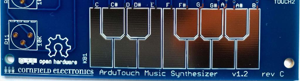
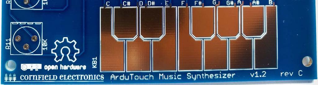
9 The board we ll solder the parts to
")


10 The tools you ll need: soldering Iron (35W or less) solder (60/40 Sn/Pb, rosin core, diameter or less) soldering iron stand cellulose kitchen sponge (not plastic!) small wire cutter

11 R1 this is where it goes

12 R1: Brown, Black, Orange (not Brown, Black, Red)
13 R1

14 wires coming out from parts are called leads they lead to the part

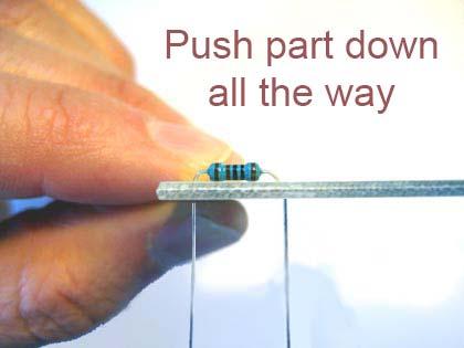
15 R1 this is how it will look before inserting it into the board

16 these are pads
17

18


19 R1 inserted into the board
20 How to hold a soldering iron (Like a pencil held from underneath)
21 The perfect kind of solder for electronics: 60/40 rosin core, diameter (or smaller) Important: Use solder WITH lead (Pb)!! Unleaded solder has very poisonous fumes!
22 3 Safety Tips
23 Safety Tip #1: Hot!! (When you touch the tip, you will let go quickly every time!)
24 Safety Tip #2: Lead (Pb) is toxic But it easily washes off your hands with soap and water
25 Safety Tip #3: (coming soon)
26 2 secrets to good soldering
27 Secret #1: Clean the tip! (before every solder connection) Bang (lightly) 3 times, Swipe, Rotate, Swipe: Keep the tip shiny silver!

28


29


!")
30 Make sure solder melts on the underside of the soldering iron (not the side or top of the soldering iron tip)!

31
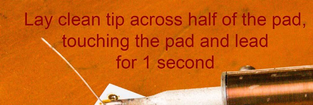
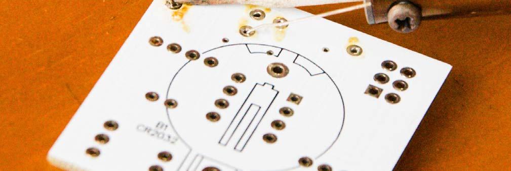
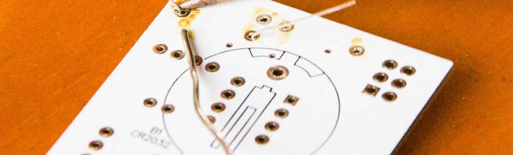
32 Secret #2: Keep hot tip down 1 second for solder to flow!!
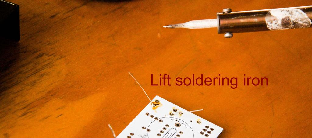
33 Now

34 If you can see any of the pad, or the hole, you need more solder so, just do all the steps again to make it perfect.

35 Cutting with the tip of the wire cutter gives you more control
36 Safety Tip #3: Hold or cover the lead! (or it will fly into your eye!)

37 No wire sticking out
 you cannot see the hole (it s totally covered with")
38 R1 soldered to the board Notice that: each connection is a small bump (not flat) you cannot see any pad (it s totally covered with solder) you cannot see the hole (it s totally covered with solder)
39 One part at a time
40 Till all the parts are soldered
41 And it will look like this when you re done.
42 Let s start!

43 If you haven t done so already, solder R1: brown, black, orange


44 R1: R2, R3, R4, R5: R6, R7: R8, R9: R13, R14, R15: 10K: Brown, Black, Orange 22M: Red, Red, Blue 270: Red, Violet, Brown 4.7K: Yellow, Violet, Red 1K: Brown, Black, Red
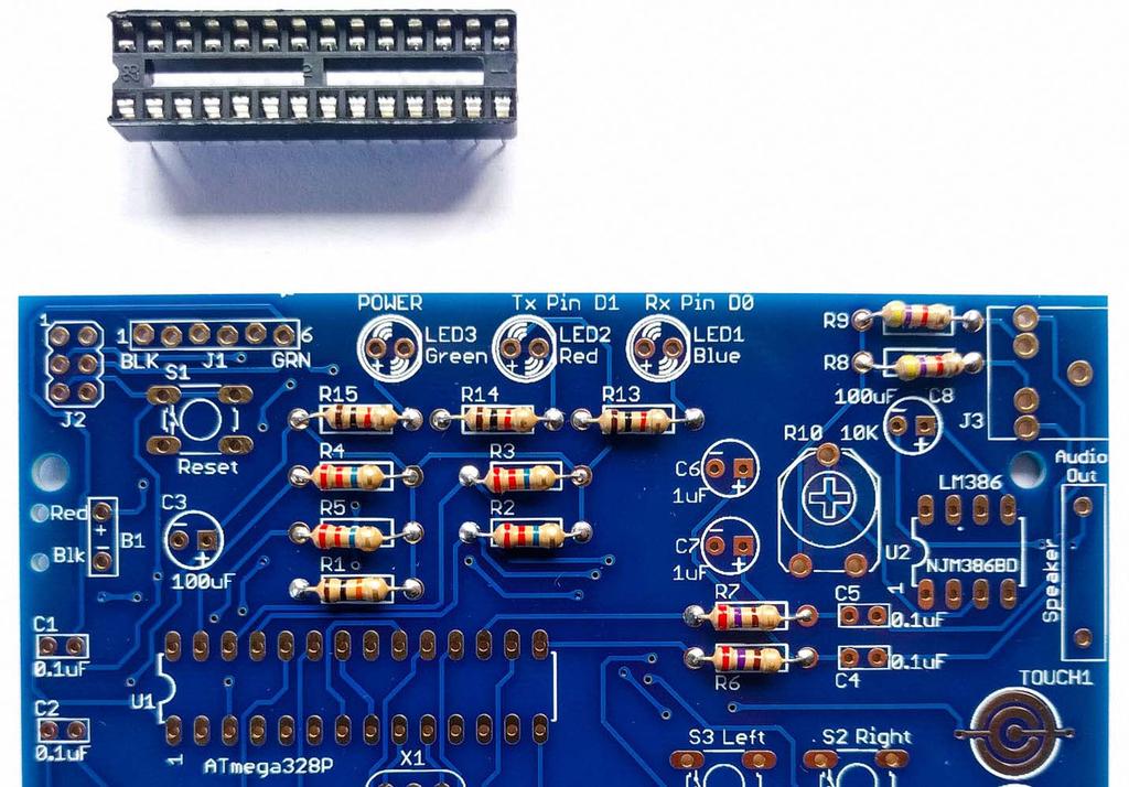
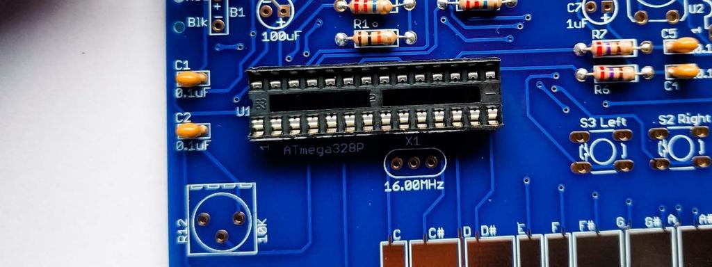
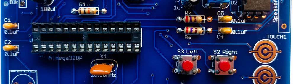
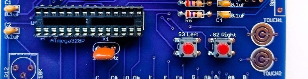
45 U1: microcontroller socket proper orientation
46 U1: microcontroller socket: inserted correctly


47 U1: microcontroller socket bend pins down on two corners, and solder all 28 leads to the board


48 U1: microcontroller socket All 28 leads soldered to the board: Notice that each has a little bump of solder (not flat).

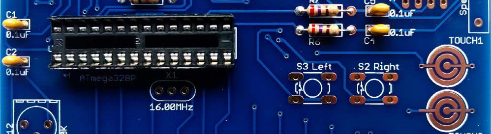
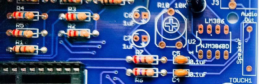
49 C1, C2, C4, C5
50 C3, C8: 100uF
51 C6, C7: 1uF

52 C3, C8: 100uF

53 C3, C8: Long Lead +


54 C3, C8: 100uF soldered to board

55 C6, C7: 1uF


56 C6, C7: Long Lead +


57 C6, C7: 1uF soldered to board


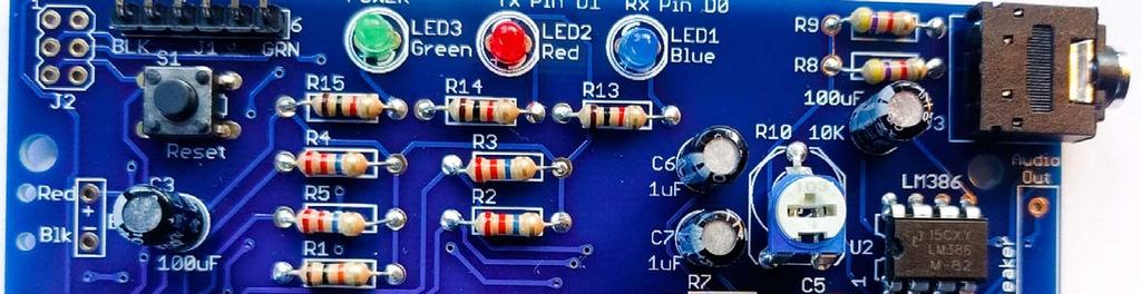
58 LED1, LED2, LED3: Long Lead + We ll use them for the speaker

59 LED1, LED2, LED3 Green, Red, Blue soldered to board

60 long leads short leads J1


61 Short leads into board J1 short leads go into the board long leads sticking out from board


62 (if it falls out, solder one lead on the top of the board, then turn over the board and solder the other 5 leads) J1

63 S1: black Reset button

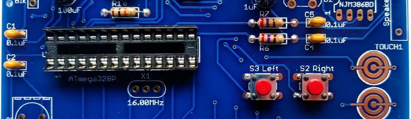
64 S2, S3: Red buttons


65 X1 The orientation of X1 does not matter. (Note: X1 may be yellow or blue)

66 U2 Note: this chip may be marked differently, but 386 will be printed on it somewhere.

67 U2 When chips are new, their pins are bent out.
 bend the leads.")
68 U2 We need the pins bent straight and parallel. Use your work table to (gently) bend the leads.

69 U2 Gently bend leads so they re straight and parallel

70 U2: audio amp chip proper orientation
71 U2: inserted correctly
72 U2 bend pins down on two corners, and solder all 8 leads to the board
73 U2 soldered to board

74 R10: volume control When new, the pins point straight down.

75 R10: volume control We need to bend them out a little to fit into the board.

76 R10: volume control

77 J3: headphone / output jack
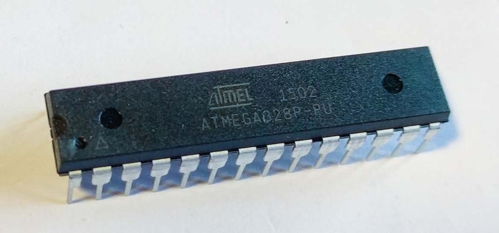
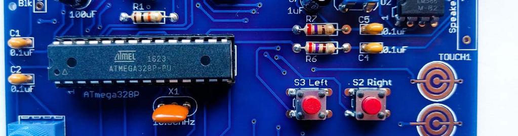
78 U1: microcontroller


79 U1: microcontroller the kit comes with these pins already bent straight and parallel
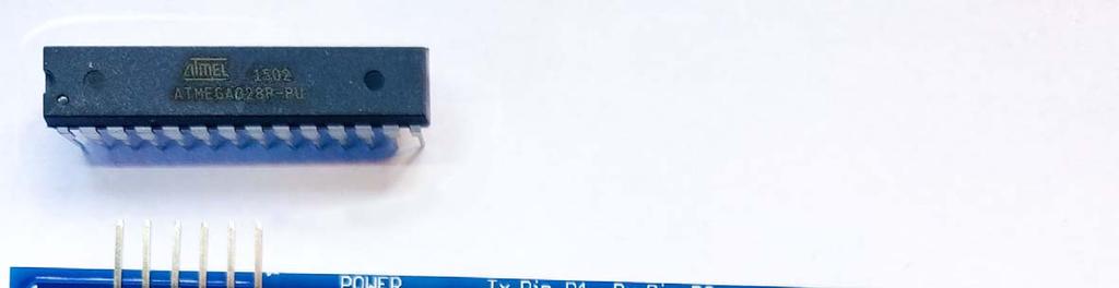
80 proper orientation U1: microcontroller
81 U1: microcontroller make sure each pins rests in its hole in the socket with the proper orientation


82 Use two thumbs to push microcontroller into the socket Make sure all 28 pins are in place, and push it into its socket. (This is actually way easier with 2 thumbs.) U1: microcontroller


 pry out chip,")
83 U1: microcontroller Inspect all pins, and be sure each went into its hole in the socket not bent. If any pins are bent, (gently) pry out chip, straighten pins, and insert again.


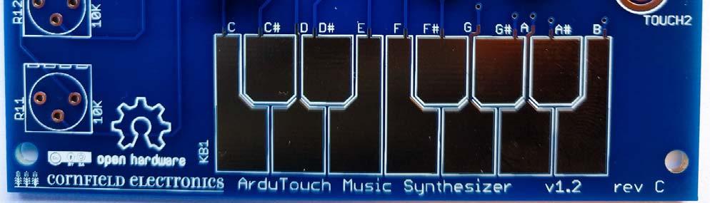
84 R11 & R12: potentiometers

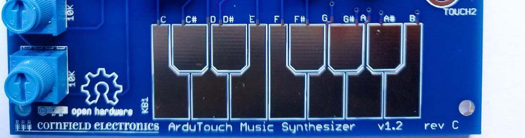
85 R11 & R12: potentiometers
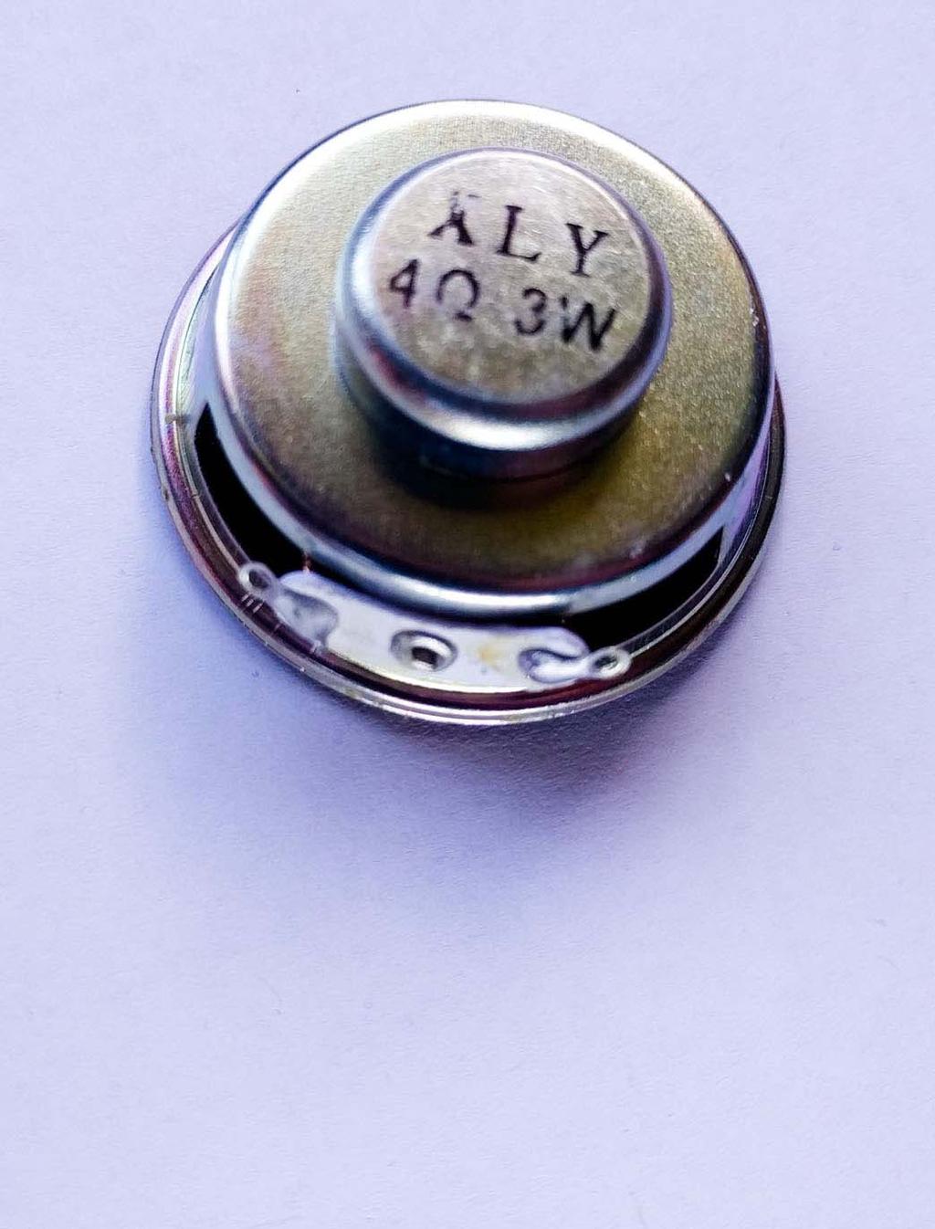
86 Speaker

87 We ll add leads to the speaker Speaker from the LEDs


88 Tin one side of each lead (i.e., cover with thin film of melted solder) Speaker
89 Solder one lead to speaker Notice the correct place to solder the wire Speaker


90 Solder next lead to speaker Speaker Notice the correct place to solder the wire


91 Insert speaker into board and solder both leads to board. Speaker


92 Push battery pack leads through holes. Make sure Red and Black go through their correct holes! Battery pack
93 Loop one lead into its pad, and solder. Then loop the other lead into its pad, and solder. Battery pack
94 Done!


95 Let s make noise!
Soldering is easy. here's how to do it. Andie Nordgren (Comics adaptation) Jeff Keyzer. by: Mitch Altman (soldering wisdom) (Layout and editing)
 Jeff Keyzer. by: Mitch Altman (soldering wisdom) (Layout and editing)") Soldering is easy here's how to do it by: Mitch Altman (soldering wisdom) Andie Nordgren (Comics adaptation) Jeff Keyzer (Layout and editing) Download this comic book and share it with your friends! Distribute
Soldering is easy here's how to do it by: Mitch Altman (soldering wisdom) Andie Nordgren (Comics adaptation) Jeff Keyzer (Layout and editing) Download this comic book and share it with your friends! Distribute
LDB-1 Kit Instructions Page 1 of 8
 LDB-1 Kit Instructions Page 1 of 8 Important Information Congratulations and thank you for your purchase of the LDB-1 Little Drummer Boy Analog Drum Machine Kit! Before you start, please read the enclosed
Circuit Board Assembly Instructions for Babuinobot 1.0
 Circuit Board Assembly Instructions for Babuinobot 1.0 Brett Nelson January 2010 1 Features Sensor4 input Sensor3 input Sensor2 input 5v power bus Sensor1 input Do not exceed 5v Ground power bus Programming
Electronics Merit Badge Class 4. 12/30/2010 Electronics Merit Badge Class 4 1
 Electronics Merit Badge Class 4 12/30/2010 Electronics Merit Badge Class 4 1 Soldering Safety Note: A Soldering Iron gets hotter than 374 F. Do not touch the soldering iron s metal parts or you will receive
Heartboard PCB Assembly Instructions
 Heartboard PCB Assembly Instructions Thanks for purchasing a Heartboard! These instructions will guide you through assembling and testing the Heartboard. Let s get started! Stuff you need Soldering iron
Introduction 1. Download socket (the cable plugs in here so that the GENIE microcontroller can talk to the computer)
") Introduction 1 Welcome to the magical world of GENIE! The project board is ideal when you want to add intelligence to other design or electronics projects. Simply wire up your inputs and outputs and away
Introduction 1 Welcome to the magical world of GENIE! The project board is ideal when you want to add intelligence to other design or electronics projects. Simply wire up your inputs and outputs and away
Mono Amplifier. LM386 Headphone Amp
 Mono Amplifier LM386 Headphone Amp Layout On/Off Switch - cuts power to the circuit Mono Input Jack: use either L or R or solder together Schematic Step 1 - Parts List 1.) R1-10ohm Resistor - Brown Black
Bill of Materials: Metronome Kit PART NO
 Metronome Kit PART NO. 2168325 The metronome kit allows you to build your own working electronic metronome. Features include a small speaker, flashing LED, and the ability to switch between several different
Custom Front Panel Upgrade Instructions
 Custom Front Panel Upgrade Instructions Here are the directions for upgrading your SP-II to an SP-IIB, with a custom blackanodized front panel and engraved lettering. There are only forty SP-IIB s in existence
Lighthouse Beginner s soldering kit
 Lighthouse Beginner s soldering kit Kit contains: 1 x 220 ohm resistor (Red, Red, Black) 1 x 82k ohm resistor (Grey, Red, Orange) 2 x 220k ohm resistors (Red, Red, Yellow) 2 x Diodes 1 x Power switch 1
STEADY HAND GAME WITH LATCHING LED
 ESSENTIAL INFORMATION BUILD INSTRUCTIONS CHECKING YOUR PCB & FAULT-FINDING MECHANICAL DETAILS HOW THE KIT WORKS TEST YOUR HAND-EYE COORDINATION WITH THIS STEADY HAND GAME WITH LATCHING LED Version 2.0
Gertboard Assembly Manual Rev 1.1
 Gertboard Assembly Manual Rev 1.1 The Gertboard is an add-on GPIO expansion board for the Raspberry Pi computer. It comes with a large variety of components, including buttons, LEDs, A/D converters, DACs,
Any Questions? Contact us or Alligator Blinkie
 Alligator Blinkie The heart of this blinkie is a 12F1822 PIC produced by a company called Microchip. A PIC is a tiny, yet surprisingly powerful little computer. By itself, it can t do much it needs someway
Installation tutorial for Console Customs PS3 TrueFire Standard Rapid fire Microchip for Sixaxis and Dualshock 3 controllers
 Installation tutorial for Console Customs PS3 TrueFire Standard Rapid fire Microchip for Sixaxis and Dualshock 3 controllers This tutorial is designed to aid you in installation of a console customs rapid
THE THUNDERDRIVE (K-950)
") THE THUNDERDRIVE (K-950) OUTPUT DISTORTION Unplug when not in use to save battery life. TO AMP IN The Thunderdrive Modkitsdiy.com FROM GUITAR OUT Use these instructions to learn: How to build an effects
THE THUNDERDRIVE (K-950) OUTPUT DISTORTION Unplug when not in use to save battery life. TO AMP IN The Thunderdrive Modkitsdiy.com FROM GUITAR OUT Use these instructions to learn: How to build an effects
Find a place where you can work through completion, without disturbing your
 Scan by Manual Manor ARIES SYSTEM 300 MUSIC SYNTHESIZER Page I of 4 MODULE AR-334 SEQUENCER ASSEMBLY INSTRUCTIONS It is recommended that you do the following before you proceed: Find a place where you
SoftRock v5.0 Builder s Notes. December 12, Building a QSD Kit
 SoftRock v5.0 Builder s Notes December 12, 2005 Building a QSD Kit Be sure to use a grounded tip soldering iron in building the QSD board. The soldering iron needs to have a small tip, (0.05-0.1 inch diameter),
Any Questions? Contact us or BSA Atomic Blinkie
 BSA Atomic Blinkie The heart of this blinkie is a tiny electronic chip embedded in each of the three LEDs. When power is applied, the chip tells the LED to turn on and off, or fade different colors By
4ms SCM Breakout. Kit Builder's Guide for PCB v2.1 4mspedals.com
 4ms SCM Breakout Kit Builder's Guide for PCB v2.1 4mspedals.com Shuffling Clock Multiplier Breakout This guide is for building a Shuffling Clock Multiplier Breakout module (SCMBO) version 2.1 from the
SPACE WAR GUN KIT MODEL K-10. Assembly and Instruction Manual. Elenco Electronics, Inc.
 SPACE WAR GUN KIT MODEL K-10 Assembly and Instruction Manual Elenco Electronics, Inc. Copyright 1989 Elenco Electronics, Inc. Revised 2001 REV-H 753210A PARTS LIST Contact Elenco Electronics (address/phone/e-mail
Minty Amp assembly instructions
 Minty Amp assembly instructions Parts Required: LM386 OpAmp (included in kit) 2x 100uf (min 16v) Electrolytic Capacitors (included in kit) 0.1uf Ceramic Capacitor (included in kit) 0.047uf Ceramic Capacitor
Assembly Instructions
 Assembly Instructions For the SSQ-2F 3.1 MHz Rife Controller Board Kit v1.41 Manual v1.00 2012 by Ralph Hartwell Spectrotek Services GENERAL ASSEMBLY INSTRUCTIONS Arrange for a clean work surface with
Assembly Instructions for the 1.5 Watt Amplifier Kit
 Assembly Instructions for the 1.5 Watt Amplifier Kit 1.) All of the small parts are attached to a sheet of paper indicating both their value and id. 2.) Leave the parts affixed to the paper until you are
01. Parts. Blink v1.1. Battery Holder x1. Red LED x1 Green LED x1 Blue LED x1. Resistors x3. Battery x1. Blink PCB x1. Push Button Switchers x3
 Blink L1 L2 L3 01. Parts Battery Holder x1 Red LED x1 Green LED x1 Blue LED x1 Resistors x3 Learn to Solder Kit Battery x1 L1 L2 L3 Blink PCB x1 S3 Push Button Switchers x3 02. Tools RECOMENDED Soldering
GT3B Hack Kit Install Instructions Written By Austin Hutchison
 GT3B Hack Kit Install Instructions Written By Austin Hutchison Step 1: Remove 4 screws located on top of the radio. 1 Step 2: There are small plastic latches that also hold the top in place. The easiest
NERVE TESTER KIT MODEL K-20. Assembly and Instruction Manual. Elenco Electronics, Inc.
 NERVE TESTER KIT MODEL K-20 Assembly and Instruction Manual Elenco Electronics, Inc. Copyright 1989 Elenco Electronics, Inc. Revised 2002 REV-E 753220 PARTS LIST If you are a student, and any parts are
Induction Heater Coil Kit Compact low voltage, high current induction coil
 Induction Heater Coil Kit Compact low voltage, high current induction coil Model: CT-400-KIT Features and Specifications High power water cool-able copper coil PCB Layout designed to reduce eddy losses
Guitarpedalkits.com Overdrive Pedal Build Instructions
 Page 1 Guitarpedalkits.com Overdrive Pedal Build Instructions Follow the instructions in this guide to build your very own DIY overdrive pedal from GuitarPedalKits.com. If you re a first time builder,
DIODE / TRANSISTOR TESTER KIT
 DIODE / TRANSISTOR TESTER KIT MODEL DT-100K Assembly and Instruction Manual Elenco Electronics, Inc. Copyright 1988 Elenco Electronics, Inc. Revised 2002 REV-K 753110 DT-100 PARTS LIST If you are a student,
THE STEP LADDER (K-978)
") THE STEP LADDER (K-978) Footswitch True-bypass = 0 db OUTPUT INPUT Ground shunt switching on the input jack keeps the amp quiet when unplugged from the Step Ladder. Attenuator Pot Full clockwise = 0 db
THE STEP LADDER (K-978) Footswitch True-bypass = 0 db OUTPUT INPUT Ground shunt switching on the input jack keeps the amp quiet when unplugged from the Step Ladder. Attenuator Pot Full clockwise = 0 db
Installation tutorial for Console Customs Xbox 360 Dual Rapid fire Microchip for wired and wireless controllers (all versions)
") Installation tutorial for Console Customs Xbox 360 Dual Rapid fire Microchip for wired and wireless controllers (all versions) This tutorial is designed to aid you in installation of a console customs
Installation tutorial for Console Customs Xbox 360 Dual Rapid fire Microchip for wired and wireless controllers (all versions) This tutorial is designed to aid you in installation of a console customs
INSTALLATION INSTRUCTIONS
 XMOD 23 Mode Rapid Fire Mod Chip INSTALLATION INSTRUCTIONS This tutorial is designed to aid you in the installation of a XMOD Rapid Fire microchip. This installation requires soldering several wires to
Manual Version July 2007
 Manual Version 1.2 - July 2007 Page 1 Table of Contents Section1: M3 Phono Board Build...3 Phono Board Parts List...3 Preparation...4 Fitting the Valve Bases...6 Installing the Resistors...7 Starting the
Specimen Products Single Ended Stereo Amp Instruction Book
 Specimen Products Single Ended Stereo Amp Instruction Book Specimen tube amplifier designs are informed by decades of servicing and building musical instrument amps. As a result of being subjected to the
V6.2 SoftRock Lite Builder s Notes. November 17, 2006
 V6.2 SoftRock Lite Builder s Notes November 17, 2006 Be sure to use a grounded tip soldering iron in building the v6.2 SoftRock circuit board. The soldering iron needs to have a small tip, (0.05-0.1 inch
Warning: CHOKING HAZARD -Small Parts. Not for Children Under 9 yrs. Kit Recommended for Ages 12 and up.
 The Original Warning: CHOKING HAZARD -Small Parts. Not for Children Under 9 yrs. Kit Recommended for Ages 12 and up. Table of Contents Soldering.. 3 How the WASP Works.. 7 The Build...... 12 Troubleshooting......30
Asus ZenFone 2 Display Replacement
 Asus ZenFone 2 Display Replacement Replace your display if it isn't functioning correctly or if it is cracked or broken. Written By: Jessica Nguyen ifixit CC BY-NC-SA www.ifixit.com Page 1 of 14 INTRODUCTION
Xylophone Teaching Notes Issue 1.3
 Teaching Notes Issue 1.3 Product information: www.kitronik.co.uk/quicklinks/2105/ TEACHER Xylophone Index of sheets Introduction Schemes of work Answers The Design Process The Design Brief Investigation
Installation tutorial for Console Customs Xbox Mode Dual Button (RFX-5B) Rapid fire Microchip for all Wired and Wireless controllers
 Rapid fire Microchip for all Wired and Wireless controllers") Installation tutorial for Console Customs Xbox 360 5-Mode Dual Button (RFX-5B) Rapid fire Microchip for all Wired and Wireless controllers This tutorial is designed to aid you in installation of a console
Installation tutorial for Console Customs Xbox 360 5-Mode Dual Button (RFX-5B) Rapid fire Microchip for all Wired and Wireless controllers This tutorial is designed to aid you in installation of a console
SoftRock v6.0 Builder s Notes. May 22, 2006
 SoftRock v6.0 Builder s Notes May 22, 2006 Be sure to use a grounded tip soldering iron in building the v6.0 SoftRock circuit board. The soldering iron needs to have a small tip, (0.05-0.1 inch diameter),
Repairing your Porsche 928 Central Warning System (CWS) controller
 controller") Repairing your Porsche 928 Central Warning System (CWS) controller Disclaimer: This procedure is for a 1984 Porsche 928 S controller. Overview: Under the left foot pedal (dead pedal) of the Porsche 928
Repairing your Porsche 928 Central Warning System (CWS) controller Disclaimer: This procedure is for a 1984 Porsche 928 S controller. Overview: Under the left foot pedal (dead pedal) of the Porsche 928
Soldering Techniques NIAGARA COLLEGE TECHNOLOGY DEPT.
 Soldering Techniques NIAGARA COLLEGE TECHNOLOGY DEPT. Soldering 101 Soldering is the process of joining two metals together to form an electrically ll and mechanically secure bond using heat and a third
Ten Tec DDS Board Assembly Procedure
 05 May 2014 Ten Tec DDS Board Assembly Procedure You will find a photo of a completed board at the end of these instructions. Refer it whenever clarification is required. 1. AD9835 Attachment If you purchased
Read This Page First
 Read This Page First If you are reading this you know the manuals are always available at QRPKITS.com. This is version 8.0 of the manual dated 4/27/2016. There is no need to print out the whole assembly
How to solder SMD component on Awesome PCB or any other kind of PCB.
 How to solder SMD component on Awesome PCB or any other kind of PCB. Step by step tutorial, with no steps to skip. Step 1 - What do we need? Step 2 - Fixing PCB Step 3 - Preparing for soldering Step 4
THE TRILL TREMOLO (K-960)
") THE TRILL TREMOLO (K-60) DEPTH SPEED The Trill Tremolo Modkitsdiy.com Unplug when not in use to save battery life. TO AMP IN FROM GUITAR OUT Use these instructions to learn: How to build an effects pedal
THE TRILL TREMOLO (K-60) DEPTH SPEED The Trill Tremolo Modkitsdiy.com Unplug when not in use to save battery life. TO AMP IN FROM GUITAR OUT Use these instructions to learn: How to build an effects pedal
Main improvements are increased number of LEDs and therefore better temperature indication with one Celsius degree increments.
 LED Thermometer V2 (Fahrenheit/Celsius/±1 ) PART NO. 2244754 After completing this great starter kit, users will have a nice interactive LED thermometer. You will learn one principle how temperature can
A Deluxe LED Blinky That You Can Build!
 Lux Spectralis A Deluxe LED Blinky That You Can Build! Assembly Instructions Contents Step 1: Parts check... 2 Step 2: Tool check... 3 Step 3: Install the computer chip... 3 Step 4: Install the resistors...
tinycylon Assembly Instructions Contents Written by Dale Wheat Version August 2016 Visit dalewheat.com for the latest update!
 tinycylon Assembly Instructions Written by Dale Wheat Version 2.1 10 August 2016 Visit dalewheat.com for the latest update! Contents Assembly Instructions...1 Contents...1 Introduction...2 Quick Start
Assembly instructions for the CS-1 ChemShield
 Page 1 Of 6 Assembly instructions for the CS-1 ChemShield What is S.M.D SMD=Surface mount devices, like all the components does not have leads, but gets soldered onto flat solder pads. The CS-1 assembly
Building the Toothpick Audio CW Filter
 Building the Toothpick Audio CW Filter Introduction The toothpick is a simple variable bandpass audio filter designed to compliment the Splinter QRPp Trans-Receiver. The filter also contains an audio amplifier
Solder is a metallic glue that holds the parts together and forms a connection that allows electrical current to flow.
 Proper Soldering & Desoldering High Performance Ultrasonic Range Finders Techniques of a MaxBotix Sensor Materials Needed for Soldering Goggles Hands-free clamp Wire stripper Soldering iron with stand
Value Location Qty Potentiometers C1M Distortion 1 A10k Volume 1. Footswitch 3PDT SW1 1. Jacks 1/4 Mono 2 DC Power 1
 Distortion BUILD INSTRUCTIONS Thank you for your purchase of our Distortion+ kit! We have completely redesigned our entire line of kits to be the most user friendly, while still maintaining their same
iphone 1st Generation Battery Replacement Written By: irobot ifixit CC BY-NC-SA Page 1 of 15
 Written By: irobot ifixit CC BY-NC-SA www.ifixit.com Page 1 of 15 INTRODUCTION Battery not lasting long? Swap it out (requires soldering). TOOLS: Probe and Pick Set (1) Desoldering Braid (1) SIM Card Eject
INSTRUCTIONS FOR ASSEMBLY AND OPERATION
 diytube stereo 0 driver board INSTRUCTIONS FOR ASSEMBLY AND OPERATION Price $0.00 Important Note: The phase is swapped on the diytube ST0 from the orginal design. Be sure to hook up the drive lines (at
SoftRock v6.0 Builder s Notes. April 6, 2006
 SoftRock v6.0 Builder s Notes April 6, 006 Be sure to use a grounded tip soldering iron in building the v6.0 SoftRock circuit board. The soldering iron needs to have a small tip, (0.05-0. inch diameter),
Ultrasound Range Finder
 Ultrasound Range Finder PCB Version 1.0 Assembly Manual Range Finder Assembly Instructions Read This Before You Begin 1. Avoid touching the PCB copper traces and pads with your fingers until you are ready
Tek-Bot Remote Control Transmitter Board Construction
 Tek-Bot Remote Control Transmitter Board Construction Purpose This tutorial illustrates the procedure for construction of the Transmitter board for the Tek-bot. A Guide to Soldering Many of you have soldered
Assembly Instructions for B7971 Smart Socket
 Assembly Instructions for B7971 Smart Socket Identification and installation of the resistors, Fig1 Segment 1,R1, 22k Segment 4, R4, 22k Segment 2, R2, 27k Segment 3, R3, 27k Segment 5, R5, 27k Segment
STEP 0 Prepare the Materials.
 How to Build a Germanium Fuzz Guitar Effect. This document will guide you to build and test your Germanium Fuzz guitar pedal. With all the materials on hand, it takes around 2-4 hours to build it. Try
Tips in Soldering. By Jesus Beltran. Team J (AKA J Crew) EEC 134AB, Professor Xiaoguang Liu UC Davis College of Engineering
 EEC 134AB, Professor Xiaoguang Liu UC Davis College of Engineering") Tips in Soldering By Jesus Beltran Team J (AKA J Crew) EEC 134AB, 2015 16 Professor Xiaoguang Liu UC Davis College of Engineering INTRODUCTION Basic soldering skills is a trait that every electronic/electrical
Tips in Soldering By Jesus Beltran Team J (AKA J Crew) EEC 134AB, 2015 16 Professor Xiaoguang Liu UC Davis College of Engineering INTRODUCTION Basic soldering skills is a trait that every electronic/electrical
The Walford Electronics Ford Receiver Kit Project Construction Manual
 The Walford Electronics Ford Receiver Kit Project Construction Manual Walford Electronics Ford Receiver construction manual V1.5 Page 1 of 22 Introduction The Ford receiver has four stages: The first stage
Introduction. Circuit diagram
 Introduction You must have played with a dice at some time, for example when playing Ludo or Monopoly. Dice have existed for a very long time. The first known six-sided dice were found in Iraq and were
GROUND BALANCE & PINPOINT BUTTON MODIFICATION By Sven Stau October 2008
 TESORO CIBOLA GROUND BALANCE & PINPOINT BUTTON MODIFICATION By Sven Stau October 2008 Get some added performance by replacing the internal factory fixed GB with an external user friendly, fully adjustable
PS2-SMC-06 Servo Motor Controller Interface
 PS2-SMC-06 Servo Motor Controller Interface PS2-SMC-06 Full Board Version PS2 (Playstation 2 Controller/ Dual Shock 2) Servo Motor Controller handles 6 servos. Connect 1 to 6 Servos to Servo Ports and
LED ROBOT BLINKER KIT
 LED ROBOT BLINKER KIT MODEL K-17 Assembly and Instruction Manual Elenco Electronics, Inc. Copyright 1989, 1998 Elenco Electronics, Inc. Revised 2001 REV-J 753217 PARTS LIST If any parts are missing or
YAP BOX KIT MODEL K-22A YAP BOX SIX EXCITING SOUNDS. Assembly and Instruction Manual
 YAP BOX KIT MODEL K-22A YAP BOX SIX EXCITING SOUNDS Assembly and Instruction Manual Elenco Electronics, Inc. Copyright 2009, 1989 by Elenco Electronics, Inc. All rights reserved. Revised 2009 REV-H 753222
DIODE / TRANSISTOR TESTER KIT
 DIODE / TRANSISTOR TESTER KIT MODEL DT-100K 99 Washington Street Melrose, MA 02176 Phone 781-665-1400 Toll Free 1-800-517-8431 Visit us at www.testequipmentdepot.com Assembly and Instruction Manual Elenco
On a modular synthesizer, attenuators are an important building block in pretty much every part of your patch for both CV and audio duties.
 OVERVIEW For the most recent version of this document please visit www.thonk.co.uk For all technical support please visit http://bit.ly/r0nqyt on Muffwiggler. The Thonk AT-AT-AT Triple Passive Attenuator
AM RADIO KIT MODEL AM-780K. Assembly and Instruction Manual
 AM RADIO KIT MODEL AM-780K Assembly and Instruction Manual Elenco Electronics, Inc. Copyright 2007, 1999 by Elenco Electronics, Inc. All rights reserved. Revised 2007 REV-F 753108 No part of this book
Lesson 2: Soldering. Goals
 Introduction: Its time to learn how to solder. So you have met all the components needed to make a DIY Gamer, now it s time to put it together. Soldering is joining the components to the printed circuit
How to build a Cracklebox. Red Wierenga Brooklyn College Center for Computer Music October 13, 2015
 How to build a Cracklebox Red Wierenga Brooklyn College Center for Computer Music October 13, 2015 What s a Cracklebox? What s a Cracklebox? The Cracklebox was developed by Michel Waisvisz and others at
PRO 400 M401 MFP M425 CF-280A/X TONER CARTRIDGE REMANUFACTURING INSTRUCTIONS
 HP PRO 400 M401 MFP M425 CF-280A/X TONER CARTRIDGE REMANUFACTURING INSTRUCTIONS HP CF-280A/X TONER CARTRIDGE REMANUFACTURING THE HP LASERJET PRO 400 M401/MFP M425 (CF-280A/X) TONER CARTRIDGE By Mike Josiah
Digital Electronics & Chip Design
 Digital Electronics & Chip Design Lab Manual I: The Utility Board 1999 David Harris The objective of this lab is to assemble your utility board. This board, containing LED displays, switches, and a clock,
Myriad Design Altoids Piezo Preamp Construction Guide
 Myriad Design Altoids Piezo Preamp Construction Guide V2 December, 2014 1. The package should include the following items. If any of the items are missing from the package, please contact sales@stompville.co.uk.
INSPIRE VLF-3 Rev #1C Receiver Kit ASSEMBLY INSTRUCTIONS
 INSPIRE VLF-3 Rev #1C Receiver Kit ASSEMBLY INSTRUCTIONS The following assembly instructions should be followed carefully. The INSPIRE VLF-3 receiver kit is NOT a simple electronic assembly. If you follow
DC Motor. Controller. User Guide V0210
 DC Motor Controller User Guide 59757 V0210 This kit provides a great exercise of intermediate soldering skills and creates a device that enables you to control various Pitsco motors, Tamiya gearboxes,
Explorer Wiring Kit (assembled)
") Explorer Wiring Kit (assembled) For Vintage, Firestorm & Standard Series Please Read All Instructions Before Beginning. Tools you will need: Soldering Iron (35 watt preferably) Solder Wet Sponge Wire Clippers
Explorer Wiring Kit (assembled) For Vintage, Firestorm & Standard Series Please Read All Instructions Before Beginning. Tools you will need: Soldering Iron (35 watt preferably) Solder Wet Sponge Wire Clippers
MONO AMPLIFIER KIT ESSENTIAL INFORMATION. Version 3.0 CREATE YOUR OWN SPEAKER DOCK WITH THIS
 ESSENTIAL INFORMATION BUILD INSTRUCTIONS CHECKING YOUR PCB & FAULT-FINDING MECHANICAL DETAILS HOW THE KIT WORKS CREATE YOUR OWN SPEAKER DOCK WITH THIS MONO AMPLIFIER KIT Version 3.0 Build Instructions
Learn to Solder: Simon Says Stencil Kit Information & Instructions
 Learn to Solder: Simon Says Stencil Kit Information & Instructions This is considered an intermediate kit for people who have soldered through-hole components before and wish to learn how to reflow surface
PSU for LawMate 500mW Transmitters. Assembly and Operation Manual
 PSU for LawMate 500mW Transmitters Assembly and Operation Manual Introduction Thank you for purchasing LawMate 500mW Power Supply. This power supply was specifically designed for the 500mW LawMate transmitter
Assembly Manual V1R2B-Rev1.0D
 Assembly Manual V1R2B-Rev1.0D for 4 State QRP MagicBox - Solid State Transmit/Receive System Designed by: Jim Kortge, K8IQY Copyright 2009-2012 - All rights reserved This system is the result of some brainstorming
THE RING RESONATOR (K-975)
") THE RING RESONATOR (K-975) OUTPUT BOOST The Ring Resonator An Octave Up Fuzz Modkitsdiy.com 9 VDC CENTER (-) ADAPTER TO AMP IN FROM GUITAR OUT Unplug when not in use to save battery life. Use these instructions
THE RING RESONATOR (K-975) OUTPUT BOOST The Ring Resonator An Octave Up Fuzz Modkitsdiy.com 9 VDC CENTER (-) ADAPTER TO AMP IN FROM GUITAR OUT Unplug when not in use to save battery life. Use these instructions
Installation tutorial for Console Customs Xbox ONE MaxFire ONE V2 PCB
 Installation tutorial for Console Customs Xbox ONE MaxFire ONE V2 PCB This tutorial is designed to aid you in installation of a console customs MaxFire ONE V2 Circuit board in the newer Xbox One Controllers
Smartlamp SINGLE LED Kit - Construction Manual
 Smartlamp SINGLE LED Kit - Construction Manual With this construction manual and a Smartlamp Single LED Kit you can assemble your own solar lamp. It is recommended to first read the instructions before
Gat ew ay T o S pace AS EN / AS TR Class # 07. Colorado S pace Grant Consortium
 Gat ew ay T o S pace AS EN / AS TR 2500 Class # 07 Colorado S pace Grant Consortium One Minute Reports: - Can we have two data loggers? - Do you provide us with cameras? {Hardware Checkout after proposal}
Total solder points: 66 Difficulty level: beginner advanced. 15 Channel IR remote stick K8051 ILLUSTRATED ASSEMBLY MANUAL
 Total solder points: 66 Difficulty level: beginner 1 2 3 4 5 advanced 15 Channel IR remote stick K8051 Sleek designer enclosure with just 2 buttons, yet it provides acces to a stunning 15 channels. ILLUSTRATED
Learn to solder electronics with the Maker
 Learn to solder electronics with the Maker Shed Solder Badge! How to assemble the Maker Shed Badge kit. Written By: Alexander ifixit CC BY-NC-SA www.ifixit.com Page 1 of 19 INTRODUCTION The Maker Shed
METAL DETECTOR KIT MODEL K-26. Assembly and Instruction Manual ELENCO
 METAL DETECTOR KIT MODEL K-26 Assembly and Instruction Manual ELENCO Copyright 2012, 1989 by Elenco Electronics, Inc. All rights reserved. Revised 2012 REV-F 753226 No part of this book shall be reproduced
Frivolous Engineering Useless Machine Soldering Instructions
 Frivolous Engineering Useless Machine Soldering Instructions The electronics assembly for the Useless Machine is very easy to solder together. It consists of 11 parts as shown in the photo. Required tools
Value Location Qty Transistors 2N5485 Q1, Q2, 4 Q3, Q4 2N5087 Q5 1. Trim Pots 250k VTRIM 1. Potentiometers C500k Speed 1. Toggle Switch On/On Vibe 1
 P-90 BUILD INSTRUCTIONS Thank you for your purchase of our P-90 kit! We have completely redesigned our entire line of kits to be the most user friendly, while still maintaining their same great sound!
Telecaster Wiring Kits Please Read All Instructions Before Beginning. Tools you will need: Soldering tips: Removing Current Wiring: Step 1. Step 2.
 Telecaster Wiring Kits Please Read All Instructions Before Beginning. Tools you will need: Soldering Iron (35 watt preferably) Solder Wet Sponge Wire Clippers Wire Strippers 3/8 Drill Bit 5/32 Drill Bit
Pacific Antenna Field Strength Indicator Kit
 Pacific Antenna Field Strength Indicator Kit Description The Field Strength Indicator kit from Pacific Antenna provides a visual way to monitor the presence and relative strength RF fields through the
HEAT ACTIVATED SWITCH KIT
 TEACHING RESOURCES SCHEMES OF WORK DEVELOPING A SPECIFICATION COMPONENT FACTSHEETS HOW TO SOLDER GUIDE REACT TO THE TEMPERATURE WITH THIS HEAT ACTIVATED SWITCH KIT Version 2.1 Heat Activated Switch Teaching
QUASAR ELECTRONICS KIT No DRILL SPEED CONTROLLER
 QUASAR ELECTRONICS KIT No. 1074 DRILL SPEED CONTROLLER General Description If you work with an electric drill and unless you are lucky enough to own one of the most sophisticated models with speed control,
OpenROV. Guide 3 - Electronics. We will now move to the assembly of the electronics that will control the ROV. Written By: OpenROV
 OpenROV Guide 3 - Electronics We will now move to the assembly of the electronics that will control the ROV. Written By: OpenROV 2017 openrov.dozuki.com Page 1 of 33 INTRODUCTION We will introduce soldering
PSU V2 for LawMate 500mW Transmitters. Assembly and Operation Manual
 PSU V2 for LawMate 500mW Transmitters Assembly and Operation Manual Introduction Thank you for purchasing the V2 LawMate 500mW Power Supply. This power supply was specifically designed for the 500mW LawMate
Pi-Cars Factory Tool Kit
 Pi-Cars Factory Tool Kit Posted on January 24, 2013 Welcome to the factory: Welcome to where you will learn how to build a Pi-Car, we call it the Pi-Cars Factory. We hope that this page contains all you
Lead Trimming and Hand Soldering Guidelines for VPT DC-DC Converters and Accessory Products
 APPLICATION NOTE Lead Trimming and Hand Soldering Guidelines for VPT DC-DC Converters and Accessory Products DC-DC CONVERTERS AND ACCESSORIES AN002-2.0 Page 1 of 7 Contents: Introduction... 3 Lead Trimming...
Solder Practice Kit MODEL AK-100. Elenco Electronics, Inc. Lesson Manual. Elenco Electronics, Inc.
 Solder Practice Kit MODEL AK-100 Elenco Electronics, Inc. 150 W. Carpenter Avenue Wheeling, IL 60090 (847) 541-3800 http://www.elenco.com e-mail: elenco@elenco.com Lesson Manual Elenco Electronics, Inc.