Useful enhancements to the Jon Magill rose engine
|
|
|
- Aron Edwards
- 5 years ago
- Views:
Transcription

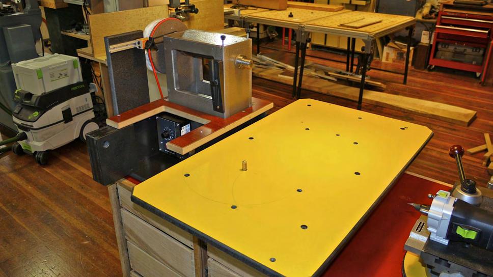
1 Useful enhancements to the Jon Magill rose engine Text and photos by Jerry Work copyright 2011, all rights reserved The Dovetail Joint, Kerby, Oregon The Jon Magill designed rose engine is a cleaver adaptation of a design by which a useful rose engine can be constructed from one half sheet of MDF and a hand full of machined parts. I purchased one of Jonʼs demonstration machines while visiting his magnificent compound on Whidbey Island, Washington over the Christmas 2010 holiday. I wanted to ornament larger objects turned on my 20 swing Powermatic lathe. The standard Magill design provides for a spindle centerline about 150mm (~6 ) above the working table, too small for my intended use. So, the first change was to lower the working table by 50mm (2 ) and to allow it to slide side to side to create a gap below the spindle to allow larger items to clear. It will now accommodate material up to 550mm (about 21.5 ) in diameter, and which project as much as 300mm (12 ) out from the spindle). The lowered bed is shown here slid back about 5 of its 11 gap travel.


2 The main bed is supported by legs that run front to back. The inboard leg slides on the bottom of the stock unit while the outboard leg slides on the top of the rose engine support cabinet. Those legs carry all the weight. Sliding and locking is accomplished by making a cut out in the back side of the rose engine equal to that on the front side of the stock unit. Two pieces of extruded aluminum T track are then fastened to the top edges of these cutouts after inserting sliding track nuts which will receive 10x32 cap screws. A simple angle iron carrier is screwed to the edges of the inboard leg front and back so the lower portion of the angle rides 1mm above the top surface of the T track as shown here by the green arrow. Tightening those two cap screws holds the table securely in place. Since I also wanted more working surface for getting around the larger pieces I intend to ornament, I wanted a working table that is both wider and longer than the stock design provides. Note the blue T track cut front to back in the top side of the stock bed in the picture above. Those T tracks secure a solid phenolic resin sliding top (the black and yellow piece) 18.5mm thick, held in the T track by full length flat steel runners, each tightened from the top by six 10x32 cap screws. Using full length steel runners that slide inside the T track allows the yellow top member to slide fully front to back overhang the stock bed. This larger sliding table is 30.5 by 18 while the stock bed is 16 by Combined with the ability to slide the table(s) side to side by 11 provides an enormous increase in working table surface so I can now get my cutting frame all around much larger pieces.
 diameter circular cross slide holders center and pivot on a 7/16 brass pivot pin. The thickness of each cross slide holder is determined by the cutting frame and holder which will be used.")

3 To accommodate precision cross slides of different sizes and working heights which will hold a variety of cutting frames, I drilled four 7/16 pivot holes part way through the yellow sliding top. 300mm (12 ) diameter circular cross slide holders center and pivot on a 7/16 brass pivot pin. The thickness of each cross slide holder is determined by the cutting frame and holder which will be used. The idea is to make sure the cutting center of the cutting frame is exactly at the centerline of the rose engine spindle. Shown here is a Festool MFK 700 EQ router which will serve as one of my cutting frames. This router is small, very quiet, and mounts easily to the black plate shown via four threaded mounting holes designed in its base. It can use both 1/4 and 8mm shank router bits so have a lot of choices including the superb Festool single point carbide engraving bit shown in more detail here. This bit produces very fine detail at the point and can also cut
 so it is a real workhorse for rose engine use.")

4 fully along the 10mm length of the brazed on carbide with ease. The routerʼs built in variable speed control allows matching the rotational speed to the cutter and the material being ornamented. The router is rated for continuous use at a 700 watt draw (close to 1hp) so it is a real workhorse for rose engine use. The top green knob is the router spindle lock so bit changes are a snap and the power cord is removable from the router to eliminate clutter when not being used. The quick change tool post sits on top of the black mounting plate locking everything to the cross slide yet still allowing a nearly unlimited range of cutter angles. When a second 300mm circular cross slide holder is placed beneath the one shown, the cross slide I use will place an AXA quick change tool post at its center line relative to the rose engine spindle so it is easy to get nearly any cutting frame centered to that spindle with a minimum of time or fuss. The next series of pictures shows just how much working room is provided by the interaction between the side to side sliding of the stock bed plus the fore-aft movement of the larger sliding table. The solid phenolic resin sliding table is very heavy so it also greatly helps dampen unwanted vibration or chatter of the cutter on the work piece. These two photos show the side to side movement of the stock bed to create the gap. The photo right shows the yellow sliding table pushed all the way rearward with the gap closed. The photo below shows the sliding table in the center position and the main bed opened to the full gap position. The cross slide holder is in the front left pivot position. The first photo on the next page shows the sliding table all the way forward with the main table in its maximum gap position.

5 This photo will give you an idea of just how large the range of table, and therefore cutting frame, movement really is. It will easily accommodate anything I can turn over the bed on my Powermatic lathe shown in the background. Once you have the tables where you want them, tightening the two main bed and four sliding table securing screws holds everything in place and rock solid. The weight is carried on the main bed legs and not on the sliding or adjustment mechanisms so the cutting frame is really stable and chatter free. This arrangement allows for four different levels of working heights relative to the spindle center line. In Jonʼs original design the working height from the bed to the spindle center is 5 3/4. With the modification outlined here you will have center heights of 7 1/2 over the stock bed, 6 3/8 over the yellow sliding table, and 10 7/8 over the gap. The limiting factor is clearing the top of the rear blue T track since the spindle is offset towards the rear. You could create a larger swing over the gap if you need it by lowering that rear blue T track but it would weaken the framework a bit. My Powermatic lathe is 10 from spindle center to bed so the 10 7/8 clearance is more than enough for my needs.


6 Following Jonʼs suggestions, I powered the spindle via a gear motor and variable speed controller. A double pole, double throw toggle switch allows for both forward and reverse rotation of the rose engine spindle. I wanted to make sure that toggle could not be accidentally bumped during use so mounted it up under the headstock bed at the rear in the top of a six gang 110v outlet box. The wires run under the spindle carrier so they are out of the way as well. The pulley I turned for the drive motor results in a spindle speed range from zero to 3.5 RPM which should be about right. One can always change that pulley diameter to raise or lower this speed range. The motor speed control box is mounted in the manual crank recess area Jon designed into the front of the unit. It is easy to reach but well out of the way of an unintentional movement during use. I also cut access holes in the bottom of the unit right under the two headstock pivot points. I found it a bit awkward to properly align the headstock rocking pivots into their

7 respective pivot bearing holes from above without a clear line of site. The first time I assembled this unit I actually missed and the pivot points were above the bearing holes just riding on the MDF. It all worked just fine and felt correct, but would not have lasted long. By looking through these access holes you can see clearly when the headstock pivot bearings are correctly positioned. The holes also provide for periodic lubrication of the pivot points without disassembly of the machine. My studio and gallery are located on the first floor of the 1907 former Masonic Temple building in historic Kerby, Oregon. The gallery is the front one fourth of this 2500 square foot space. The working studio is the middle one half of the space and the finish room and mechanical/store rooms occupy the rear one quarter of this floor. Here is a view of the relative position of the rose engine base cabinet, rose engine and lathe looking from the studio towards the gallery. There is no physical separation between the studio and gallery areas. When this photo was taken the gallery was being remodeled so is basically empty. You can see photos of it in itʼs normally jammed state on my web site

8 Note that the rose engine base cabinet I built is temporarily sitting on a Festool multifunction work table with its legs folded. Once I get more experience working with the rose engine and determine the most comfortable working height for me, then I will build a proper base for this cabinet. The cabinet has eight full extension drawers. The four wide ones will hold lathe cutting, sanding, polishing and buffing supplies while the four narrower ones will hold the rose engine components, cutting frames and supplies. I really like the convenience of being able to move work easily from the lathe to the rose engine for ornamentation and back again. I only wish the two spindles were the same size so I didnʼt have to use adapters or re-chuck the workpieces. Oh well, a 1 1/4 spindle would be over kill for the rose engine and a 1 spindle would be a bit small for the large, heavy objects I often turn on the lathe, so I guess I will have to adjust. The rose engine itself is made from MDF and finished with sprayed on black and silver Hammerite, a very durable material which is filled with microspheres. It dries to the touch in about an hour or less but takes several weeks to fully cross link and cure. Once it does, it holds up well to the stress and strain of daily use. The base cabinet is made from MDO finished with red Hammerite and edge trimmed with Oregon black oak. The drawers are made from Oregon black oak through dovetailed for strength and long service life. Here are a few more pictures to show details of these enhancements to Jonʼs very useful rose engine design.


9


10
11 About the author Jerry Work designs and hand crafts fine furniture in the 1907 former Masonic Temple building in historic Kerby, Oregon. Visitors are always welcome! Located 26 miles SW of Grants Pass, OR, on US199, the Redwood Highway Redwood Hwy PO Box 3195 Kerby, Oregon
Building stops for your Festool Kapex using the MFS profiles Text and photos by Jerry Work Copyright 2008, The Dovetail Joint, Kerby, OR
 Building stops for your Festool Kapex using the MFS profiles Text and photos by Jerry Work Copyright 2008, The Dovetail Joint, Kerby, OR Most who use the Festool Kapex compound sliding miter saw will want
THE 4224B WOODWORKING LATHE POWERMATIC.COM
 THE WOODWORKING LATHE POWERMATIC.COM POWERMATIC.COM TURN YOUR PASSION INTO SOMETHING BIGGER At Powermatic, any time we build a new machine, the word that we always keep at the top of our mind is passion.
The Festool Parallel Guides Take Guided Rail Cutting and Routing to a Whole New Level
 The Festool Parallel Guides Take Guided Rail Cutting and Routing to a Whole New Level Text and photos by Jerry Work Copyright 2009, The Dovetail Joint Those familiar with the Festool guided rail cutting
VARIABLE SPEED WOOD LATHE. Model DB900 INSTRUCTION MANUAL
 VARIABLE SPEED WOOD LATHE Model DB900 INSTRUCTION MANUAL 1007 TABLE OF CONTENTS SECTION...PAGE Technical data.. 1 General safety rules....1-3 Specific safety rules for wood lathe.....3 Electrical information.4
VARIABLE SPEED WOOD LATHE
 MODEL MC1100B VARIABLE SPEED WOOD LATHE INSTRUCTION MANUAL Please read and fully understand the instructions in this manual before operation. Keep this manual safe for future reference. Version: 2015.02.02
OPERATOR'S MANUAL RULES FOR SAFE OPERATION
 OPERATOR'S MANUAL #4950300 ROUTER AND JIG SAW MOUNTING KIT (FOR USE WITH THE BT3000 TABLE SAW) CONGRATULATIONS AND THANK YOU FOR BUYING THIS RYOBI ROUTER AND JIG SAW MOUNTING KIT. Your new #4950300 Router
Machining. Module 5: Lathe Setup and Operations. (Part 1) Curriculum Development Unit PREPARED BY. August 2013
 Curriculum Development Unit PREPARED BY. August 2013") Machining Module 5: Lathe Setup and Operations (Part 1) PREPARED BY Curriculum Development Unit August 2013 Applied Technology High Schools, 2013 Module 5: Lathe Setup and Operations (Part 1) Module Objectives
Machining Module 5: Lathe Setup and Operations (Part 1) PREPARED BY Curriculum Development Unit August 2013 Applied Technology High Schools, 2013 Module 5: Lathe Setup and Operations (Part 1) Module Objectives
Machining. Module 6: Lathe Setup and Operations. (Part 2) Curriculum Development Unit PREPARED BY. August 2013
 Curriculum Development Unit PREPARED BY. August 2013") Machining Module 6: Lathe Setup and Operations (Part 2) PREPARED BY Curriculum Development Unit August 2013 Applied Technology High Schools, 2013 Module 6: Lathe Setup and Operations (Part 2) Module Objectives
Machining Module 6: Lathe Setup and Operations (Part 2) PREPARED BY Curriculum Development Unit August 2013 Applied Technology High Schools, 2013 Module 6: Lathe Setup and Operations (Part 2) Module Objectives
1. The Lathe. 1.1 Introduction. 1.2 Main parts of a lathe
 1. The Lathe 1.1 Introduction Lathe is considered as one of the oldest machine tools and is widely used in industries. It is called as mother of machine tools. It is said that the first screw cutting lathe
GlideRite Retractable Cover System For HotSpring & Tiger River Spas (except Classic & pre-2000 Landmark Spas)
") List of Contents Quantity Description 12 #10 x 1 ½ Flat Head Phillips Screw (see pg. 2) 2 #10 x ½ Pan Head Phillips Screw (see pg. 2) 8 ¼ x 2 ½ Lag Bolt (see pg. 2) 7 ¼ 20 x 5 / 8 Hex Head Bolt (see pg.
List of Contents Quantity Description 12 #10 x 1 ½ Flat Head Phillips Screw (see pg. 2) 2 #10 x ½ Pan Head Phillips Screw (see pg. 2) 8 ¼ x 2 ½ Lag Bolt (see pg. 2) 7 ¼ 20 x 5 / 8 Hex Head Bolt (see pg.
OPERATOR'S MANUAL ROUTER MOUNTING KIT
 OPERATOR'S MANUAL MOUNTING KIT 4950301 (FOR USE WITH BT3000 AND BT3100 TABLE SAWS) Your new router mounting kit has been engineered and manufactured to Ryobi's high standard for dependability, ease of
Lathe is a machine, which removes the metal from a piece of work to the required shape & size HENRY MAUDSLAY
 TURNING MACHINES LATHE Introduction Lathe is a machine, which removes the metal from a piece of work to the required shape & size HENRY MAUDSLAY - 1797 Types of Lathe Engine Lathe The most common form
Copyright 2007 MLCS 1
 Copyright 2007 MLCS 1 REFERENCE GUIDE and SPECIFICATIONS: Edge Guides: This 12 Dovetail Template comes complete with 2 Edge Guide Sets one set for Half Blind and one set for Rabbeted Half Blind Dovetails.
Turning and Lathe Basics
 Training Objectives After watching the video and reviewing this printed material, the viewer will gain knowledge and understanding of lathe principles and be able to identify the basic tools and techniques
7x --Tailstock Cam Lock
 7x --Tailstock Cam Lock By Magic Brian magicbrian40@yahoo.com Probably the most pleasing mod to have, but often not done through lack of milling facility s This version does NOT require a mill. MATERIALS
Copyright MLCS 1
 Copyright 2007. MLCS 1 WORKING WITH BOX JOINTS Box joints (AKA "Finger Joints") provide a simple, yet equally effective, alternative to dovetail joinery. In particular, they serve well for applications
Taig Lathe Instruction Booklet 03J71.00
 Page 1 of 12 Taig Lathe Instruction Booklet 03J71.00 1. Specifications Center Height: 2.250" Distance Between Centers: 9.75" Recommended Motor: 1/6 to 1/4 hp, 1725 rpm, 1/2" arbor Accuracy:?.001" Spindle:
ALUMA-CLASSIC FENCE W1716 & W1720 INSTRUCTION MANUAL
 ALUMA-CLASSIC FENCE W1716 & W1720 INSTRUCTION MANUAL Phone: Phone: 1-360-734-3482 On-Line On-Line Technical Technical Support: Support: tech-support@woodstockint.com tech-support@shopfox.biz COPYRIGHT
Side Winder R o u t e r L i f t.
 Woodpeckers PRECISION WOODWORKING TOOLS Side Winder R o u t e r L i f t. INSTALLATION INSTRUCTIONS The wrench handle must be pointing left in order to fully insert or remove it. Lift Wrench Once fully
GlideRite Retractable Cover System For Hot Spot Spas (SE & SLX only)
") List of Contents Quantity Description 12 #10 x 1 ½ Flat Head Phillips Screw (see pg. 2) 2 #10 x ½ Pan Head Phillips Screw (see pg. 2) 8 ¼ x 2 ½ Lag Bolt (see pg. 2) 7 ¼ 20 x 5 / 8 Hex Head Bolt (see pg.
List of Contents Quantity Description 12 #10 x 1 ½ Flat Head Phillips Screw (see pg. 2) 2 #10 x ½ Pan Head Phillips Screw (see pg. 2) 8 ¼ x 2 ½ Lag Bolt (see pg. 2) 7 ¼ 20 x 5 / 8 Hex Head Bolt (see pg.
The new generation with system accessories. Made in Germany!
 1 The new generation with system accessories. Made in Germany! For face, longitudinal and taper turning, thread-cutting. For machining steel, brass, aluminium and plastic. Mounting flange for fastening
Introduction to Machining: Lathe Operation
 Introduction to Machining: Lathe Operation Lathe Operation Lathe The purpose of a lathe is to rotate a part against a tool whose position it controls. It is useful for fabricating parts and/or features
Lumber Smith. Assembly Manual. If you are having problems assembling the saw and need assistance, please contact us at:
 Lumber Smith Assembly Manual If you are having problems assembling the saw and need assistance, please contact us at: 804-577-7398 info@lumbersmith.com 1 Step 1 Safety Carefully read the Owners Manual.
SAFETY INSTRUCTIONS. Wear protective clothing, including safety glasses and steel toe boots.
 SAFETY INSTRUCTIONS Wear protective clothing, including safety glasses and steel toe boots. DO NOT allow loose clothing or long hair near machine operations. Keep work site and machine clean. Use brush
The new generation with system accessories. Made in Germany!
 1 The new generation with system accessories. Made in Germany! For face, longitudinal and taper turning, thread-cutting. For machining steel, brass, aluminium and plastic. Mounting flange for fastening
Fig2: The Sliding Glue Block from the back.
 Ornament Stand Introduction It was one of those forehead smacking moments. I was taking the #2 jaws off my Stronghold chuck, to put on my homemade wooden two jaw chuck set-up. For some reason instead of
Lathe Accessories. Work-holding, -supporting, and driving devices
 46-1 Lathe Accessories Divided into two categories Work-holding, -supporting, and driving devices Lathe centers, chucks, faceplates Mandrels, steady and follower rests Lathe dogs, drive plates Cutting-tool-holding
Woody s Workshop Tooling for Clock Making
 Using the Sherline Headstock Motor for Clock Wheel cutting. Background In order to cut clock wheels on a lathe it is necessary to have a method of indexing the lathe chuck to the correct number of teeth
M910 - Heavy Duty Wood Lathe 520mm Swing x 975mm Between Centres $4, $4, Product Brochure For W685. Features.
 M910 - Heavy Duty Wood Lathe 520mm Swing x 975mm Between Centres Ex GST Inc GST $4,150.00 $4,565.00 ORDER CODE: W685 MODEL: M910 Swing Over Bed (mm): 520 Between Centres (mm): 975 Spindle Nose Thread:
model tsa-sa48 Sliding Crosscut Table installation guide
 model tsa-sa48 Sliding Crosscut Table installation guide A Note About Color Variations Among Anodized Aluminum Components Congratulations on the purchase of this SawStop Sliding Crosscut Table. We at SawStop
Chapter 22: Turning and Boring Processes. DeGarmo s Materials and Processes in Manufacturing
 Chapter 22: Turning and Boring Processes DeGarmo s Materials and Processes in Manufacturing 22.1 Introduction Turning is the process of machining external cylindrical and conical surfaces. Boring is a
ROOP LAL Unit-6 Lathe (Turning) Mechanical Engineering Department
 Mechanical Engineering Department") Notes: Lathe (Turning) Basic Mechanical Engineering (Part B) 1 Introduction: In previous Lecture 2, we have seen that with the help of forging and casting processes, we can manufacture machine parts of
Notes: Lathe (Turning) Basic Mechanical Engineering (Part B) 1 Introduction: In previous Lecture 2, we have seen that with the help of forging and casting processes, we can manufacture machine parts of
An Improved Tool Support for a Harbor Freight Tool Grinder, version 2.2
 An Improved Tool Support for a Harbor Freight Tool Grinder, version 2.2 By R. G. Sparber Copyleft protects this document. 1 Advisory This article was written with a hobby machinist a bit above novice in
TU-3008G - Opti-Turn Bench Lathe 300 x 700mm Turning Capacity Geared Head-Stock & Enclosed Gearbox
 TU-3008G - Opti-Turn Bench Lathe 300 x 700mm Turning Capacity Geared Head-Stock & Enclosed Gearbox Ex GST Inc GST $3,460.00 $3,979.00 ORDER CODE: MODEL: Swing Over Bed (mm): Distance Between Centres (mm):
INSTALLATION INSTRUCTIONS FOR INSTALLING T-SERIES EXTRA HEAVY DUTY LEVER LOCKSET
 HIGH EDGE 2 1/4"(57mm) 03079400070 INSTALLATION INSTRUCTIONS FOR INSTALLING T-SERIES EXTRA HEAVY DUTY LEVER LOCKSET IMPORTANT: THIS LOCK IS NON-HANDED. LOCK IS FACTORY PACKED PREADJUSTED FOR 1³ ₄" (45mm)
Sliding Crosscut Table installation guide
 Sliding Crosscut Table installation guide model tsa-sa48 A Note About Color Variations Among Anodized Aluminum Components Congratulations on the purchase of this SawStop Sliding Crosscut Table. We at SawStop
JET 12" Sliding Dual Bevel Compound Miter Saw
 JET 12" Sliding Dual Bevel Compound Miter Saw The JET (#JMS-12SCMS) 12" Sliding Dual Bevel Compound Miter Saw expands the wide-ranging capabilities of the SCMS (sliding compound miter saw) with the increased
An Adjustable Threading Feed Attachment for a Lathe Without Metric Threading Capability, by Ted Clarke
 An Adjustable Threading Feed Attachment for a Lathe Without Metric Threading Capability by Ted Clarke Metric pitch threads, with the exception of the Royal Microscopical Society (RMS) 36 threads per inch
Woodline USA Woodline Spacer Fence System
 Woodline USA Woodline Spacer Fence System MADE IN THE USA Includes: (1) ¼ Spacer Fence (1) 3/8 Spacer Fence (1) ½ Spacer Fence (1) Hardware Package (1) 3 Piece Brass bar set (2) Setup Blocks Visit Us Online
The new generation with system accessories. Made in Europe!
 1 The new generation with system accessories. Made in Europe! Of cast iron, wide-legged prismatic guide. For vibration-free work even at high loads. Rear flange for mounting the mill/drill head PF 230.
HOME WORKSHOP HANDBOOK Rugged BENCH GRINDER. By JOEL B. LONG
 6 HOME WORKSHOP HANDBOOK Rugged BENCH GRINDER W By JOEL B. LONG ITH this bench grinder you can keep your cutting tools sharp and do general offhand grinding, and can, with the aid of various attachments,
MODEL T " HELICAL CUTTERHEAD INSTALLATION INSTRUCTIONS
 MODEL T27696 12" HELICAL CUTTERHEAD INSTALLATION INSTRUCTIONS For questions or help with this product contact Tech Support at (570) 546-9663 or techsupport@grizzly.com Introduction The Model T27696 indexable
Basic Installation HOFFMANN KEY HOFFMANN KEY. Page Revised: DEC. 2017
 Basic Installation Frame Assembly If you received the shutter disassembled, you will first have to assemble the frame. All frames are routed to accept a Hoffmann Key. Position the four frame pieces face
Swing over bed 17.3" Center height 8.6" Swing over cross slide 9.4" Distance between centers 39.3" Width of bed 11.8"
 MODEL KL1640 PLUS Swing over bed 17.3" Center height 8.6" Swing over cross slide 9.4" Distance between centers 39.3" Width of bed 11.8" Spindle speed L:50-355 rpm, H:352-2500 rpm Spindle number 2 Spindle
Lathe. A Lathe. Photo by Curt Newton
 Lathe Photo by Curt Newton A Lathe Labeled Photograph Description Choosing a Cutting Tool Installing a Cutting Tool Positioning the Tool Feed, Speed, and Depth of Cut Turning Facing Parting Drilling Boring
USER MANUAL & PARTS LIST MODEL 136A S/N:
 NUMBERALL STAMP & TOOL CO., INC. USER MANUAL & PARTS LIST MODEL 136A S/N: P.O. BOX 187, 1 HIGH ST. SANGERVILLE, ME 04479 www.numberall.com office@numberall.com TEL: 207-876-3541 FAX: 207-876-3566 MODEL
MANUFACTURING TECHNOLOGY
 MANUFACTURING TECHNOLOGY UNIT V Machine Tools Milling cutters Classification of milling cutters according to their design HSS cutters: Many cutters like end mills, slitting cutters, slab cutters, angular
Introduction. Rocky Mountain Westy Swing Away Carrier Kit Installation Instructions
 Rocky Mountain Westy Swing Away Carrier Kit Installation Instructions Introduction Thank you for purchasing the Rocky Mountain Westy Swing Away Carrier Kit. We pride ourselves in the products we develop
USER MANUAL & PARTS LIST MODEL 40B S/N:
 NUMBERALL STAMP & TOOL CO., INC. USER MANUAL & PARTS LIST MODEL 40B S/N: P.O. BOX 187, 1 HIGH ST. SANGERVILLE, ME 04479 www.numberall.com office@numberall.com TEL: 207-876-3541 FAX: 207-876-3566 MODEL
NUMBERALL STAMP & TOOL CO., INC. USER MANUAL & PARTS LIST S/N: P.O. BOX 187, 1 HIGH ST. SANGERVILLE, ME TEL: FAX:
 NUMBERALL STAMP & TOOL CO., INC. USER MANUAL & PARTS LIST MODEL 301 S/N: P.O. BOX 187, 1 HIGH ST. SANGERVILLE, ME 04479 www.numberall.com office@numberall.com TEL: 207-876-3541 FAX: 207-876-3566 MODEL
AK846 Sander/Planer Kit and AK845 GRS Adapter Instruction Handbook
 AK846 Sander/Planer Kit and AK845 GRS Adapter Instruction Handbook The Foredom Electric Company 16 Stony Hill Road, Bethel, CT 06801 203-792-8622 fax: 203-796-7861 www.foredom.com FOREDOM Sander/Planer
SAVE THIS FOR FUTURE REFERENCE THIS PRODUCT IS FOR PROFESSIONAL LABORATORY USE ONLY USER'S MANUAL
 DENTAL, INC. TECHNICAL BULLETIN G801-022510 5860 FLYNN CREEK ROAD READ ALL INSTRUCTIONS P.O. BOX 106 BEFORE PROCEEDING COMPTCHE, CALIFORNIA, U.S.A. 95427-0106 SAVE THIS FOR FUTURE REFERENCE www.wellsdental.com
Customer Notice: Congratulations again on your SawStop purchase, and thank you! -SawStop Tualatin, OR
 Customer Notice: Congratulations on the purchase of this Sliding Crosscut Attachment. As the owner of a SawStop saw, you are familiar with our high standards for quality, fit and finish. Different from
Preference Collection and Treatment Console INSTALLATION GUIDE
 Preference Collection 5580.69 and 5580.96 Treatment Console INSTALLATION GUIDE WARNING Failure to install the 5580 as described in this installation guide may cause the unit to collapse, resulting in serious
The premier source of parts and accessories for mini lathes and mini mills. Mini Lathe User s Guide. from LittleMachineShop.com
 The premier source of parts and accessories for mini lathes and mini mills. Mini Lathe User s Guide from LittleMachineShop.com Copyright 2002, LittleMachineShop.com All rights reserved. Some photos Copyright
TABLE OF CONTENTS MODEL 8750/8800 OCL
 TABLE OF CONTENTS MODEL 8750/8800 OCL Warranty Registration...2 Warranty...3 Vehicle Preparation...4 Attaching the Lathe using Universal Plates (8750)...5 Threaded Plates (RED)...6 Unthreaded Plates (BLUE)...7
Procedure for Longworth Chuck construction
 Procedure for Longworth Chuck construction Overall construction The Longworth chuck is composed of three major components. Connected to the lathe spindle is some device that fastens to the first of two
Cut-True 16M Manual Paper Cutter
 Cut-True 16M Manual Paper Cutter 2/2013 OPERATOR MANUAL FIRST EDITION TABLE OF CONTENTS TOPIC PAGE Specifications 1 Safety Guidelines 1 Assembly 2 Overview 3 Description of Equipment Parts 3-4 Operation
Stage 2: Preparing the door (read in conjunction with Hole Drilling Options on back of Template).
.") There are three stages to fitting the CL100 mortise case: Stage 1: Marking out the position of the lock. Stage 2: Preparing the door by mortising and drilling holes. Stage 3: Fitting lock, door furniture,
There are three stages to fitting the CL100 mortise case: Stage 1: Marking out the position of the lock. Stage 2: Preparing the door by mortising and drilling holes. Stage 3: Fitting lock, door furniture,
Inventory (Figure 2)
") MODEL T10127 12" SPIRAL CUTTERHEAD INSTRUCTIONS The Model T10127 indexable insert spiral cutterhead is designed to replace the straightknife cutterhead from the Grizzly jointer Model G0609. The total procedure
MODEL T10127 12" SPIRAL CUTTERHEAD INSTRUCTIONS The Model T10127 indexable insert spiral cutterhead is designed to replace the straightknife cutterhead from the Grizzly jointer Model G0609. The total procedure
Complete Dovetail Jig Instructions
 Complete Dovetail Jig Instructions 15 18 4 3 1 12 13 8 19 17 16 6 14 5 9 11 10 2 9 PARTS LIST - Complete Dovetail Jig Introduction Your new dovetail jig will cut Full Through Dovetails and three varieties
Installation Instructions
 Supafold Slide Aside System Three Fold Room Divider Installation Instructions Distinctive Doors Ltd Supafold Slide Aside Internal Folding System IMPORTANT: Before proceeding with the installation, and
Extendable Large Dovetail Jig
 Extendable Large Dovetail Jig Instruction Manual Part # 3458 CAUTION: Please read, understand, and follow all manufacturers instructions, guidelines and owners manuals that come with your power tools.
ABM International, Inc.
 ABM International, Inc. Lightning Stitch required 1 1.0: Parts List head and motor assembly (Qty. 1) Reel stand (Qty. 1) Needle bar frame clamp (Qty. 1) Motor drive (Qty. 1) 2 Cable harness with bracket
INSTRUCTIONS FOR VARIABLE WORKTOP JIG MM
 INSTRUCTIONS FOR VARIABLE WORKTOP JIG 250-1000MM Please read these following points carefully before cutting: 1. Before using the jig we recommend you practice a few joints with off-cuts of worktops or
Precision made in Germany. As per DIN The heart of a system, versatile and expandable.
 1 Precision made in Germany. As per DIN 8606. The heart of a system, versatile and expandable. Main switch with auto-start protection and emergency off. Precision lathe chuck as per DIN 6386 (Ø 100mm).
20" WOODTURNING LATHE Model 3520A
 20" WOODTURNING LATHE Model 3520A Instruction Manual & Parts List M-0460221 (800) 248-0144 www.powermatic.com SPECIFICATIONS: 3520A Lathe Table with standard extensions... 28 x 38 Distance Between Centers...
ULTIMATE ROUTER TABLE PLANS. By Dan Phalen
 ULTIMATE ROUTER TABLE PLANS By Dan Phalen January 2017 Ultimate Router Table Plans. Copyright 2012-2017 by Daniel Phalen. Published by Creston Hall Publishing Company. All rights reserved. No part of this
Drilling. Drilling is the operation of producing circular hole in the work-piece by using a rotating cutter called DRILL.
 Drilling Drilling is the operation of producing circular hole in the work-piece by using a rotating cutter called DRILL. The machine used for drilling is called drilling machine. The drilling operation
Note: This assembly instruction will cover all configurations of Alloy adjustable height double bases.
 Note: This assembly instruction will cover all configurations of adjustable height double bases. 1 Screw in the provided adjustable glides into each leg as shown in Figure A. Two glides per leg. Figure
BLACK HOLE DUST CATCHER Assembly and Installation Instructions
 BLACK HOLE DUST CATCHER Assembly and Installation Instructions By: Contents 1. Heavy Duty Aluminum track 1 each 2. Large heavy duty knobs 2 each 3. ¼ x 20 x 1 ¾ T bolts 4 each 4. ¼ x 20 nuts and washers
User s Manual. A highly versatile chuck featuring easy to attach and release jaws for midi- and full-sized woodworking lathes
 User s Manual Barracuda 5 Quick-Change Jaw System Chuck A highly versatile chuck featuring easy to attach and release jaws for midi- and full-sized woodworking lathes #CSCBARR5 IMPORTANT: Read this manual
NEXT ARE (6) BLOCKS THAT MEASURE 7/8"+ (.885") THICK X 1-1/4"+ (1.255") TALL X 1-1/2" (1.500") LONG. SAME DRILL AND TAP PATTERN AS THE 4 ABOVE!!!
 BLOCKS THAT MEASURE 7/8+ (.885) THICK X 1-1/4+ (1.255) TALL X 1-1/2 (1.500) LONG. SAME DRILL AND TAP PATTERN AS THE 4 ABOVE!!!") 1"- 2" - 3" BLOCKS HAVE (4 total) TAPPED 1/4" X 20 in 1" thick face alone AND (2) TAPPED HOLES 3/8" X 16 IN 1" THICKNESS AS SHOWN. BLOCKS ALSO HAVE (6) DRILLED 25/64" HOLES WITH (8) 9/16" COUNTER-BORES
1"- 2" - 3" BLOCKS HAVE (4 total) TAPPED 1/4" X 20 in 1" thick face alone AND (2) TAPPED HOLES 3/8" X 16 IN 1" THICKNESS AS SHOWN. BLOCKS ALSO HAVE (6) DRILLED 25/64" HOLES WITH (8) 9/16" COUNTER-BORES
MINI-LATHE QUICK CHANGE TOOL POST
 MINI-LATHE QUICK CHANGE TOOL POST Cutting and assembly details Machinists should familiarize themselves with the contents of this section before jumping in to the drawings. Many details are described here
TIRE RACK INSTALLATION INSTRUCTIONS Dodge Sprinter
 Aluminess Products Inc 9402 Wheatlands Ct. #A Santee, CA 92071 619-449-9930 TIRE RACK INSTALLATION INSTRUCTIONS 07-11 Dodge Sprinter Please read before beginning Stainless steel hardware may bind together
CONTENTS PRECAUTIONS BEFORE STARTING OPERATION PREPARATION FOR OPERATION CAUTIONS ON USE OPERATION
 CONTENTS PRECAUTIONS BEFORE STARTING OPERATION ------------------------------------- 1 PREPARATION FOR OPERATION 1. Adjustment of needle bar stop position ---------------------------------------------------------
HOLD IT. EVEN PRESSURE. ODD SIZES. INTRODUCING THE AUTO-PRO AUTO-ADJUST TOGGLE AND DOG CLAMPS, DOG PEG TABLE FENCES AND BRACKETS BY ARMOR TOOL
 HOLD IT. INTRODUCING THE AUTO-PRO TOGGLE AND DOG CLAMPS, DOG PEG TABLE FENCES AND BRACKETS BY ARMOR TOOL EVEN PRESSURE. ODD SIZES. PATENTED MECHANISM 888.695.3055 armor-tool.com TABLE OF CONTENTS Auto-Pro
MODEL H " BYRD SHELIX CUTTERHEAD INSTRUCTIONS
 MODEL H9291 12" BYRD SHELIX CUTTERHEAD INSTRUCTIONS The Model H9291 12" Byrd Shelix cutterhead is designed to replace the straight-knife cutterhead on the Grizzly jointer Model G0609. The total procedure
Assembly Instructions 10 X 10 Aluminum Roof Support
 Assembly Instructions 10 X 10 Aluminum Roof Support Aluminum Roof Support Bolt Package 16-5/16 X 2 ¼ SS Bolt 24-5/16 X 1 SS Bolt 40-5/16 SS Nylon Lock Nuts 16-5/16 SS Flat Washers 28-4 ½ Wood Screws 36-1
INSTALLING YOUR NEW SPRING LIFT ARM KIT
 INSTALLING YOUR NEW SPRING LIFT ARM KIT 1. Measure the distance that the roof is to be raised. [If your lift system is completely non-functional, you will need to calculate or estimate this distance as
Clock 35 - Toyland. Construction instructions for Clock 35
 This clock has been designed for children, it is a stand-alone unit and can be positioned on a shelf or cabinet out of the reach of very young hands who may be tempted to touch. The clock is shown in two
Tri- State Consulting Co. Engineering 101 Project # 2 Catapult Design Group #
 Tri- State Consulting Co. Engineering 101 Project # 2 Catapult Design Group # 8 12-03-02 Executive Summary The objective of our second project was to design and construct a catapult, which met certain
A Quick-Change Gearbox For The 7x Minilathe
 A Quick-Change Gearbox For The 7x Minilathe Richard Hagenbuch 10 August 2002 This article describes how to a build a quick-change gearbox for your 7X minilathe. I'll describe one that I built as a prototype
MODEL T10815 GRINDING ATTACHMENTS INSTRUCTIONS
 MODEL T10815 GRINDING ATTACHMENTS INSTRUCTIONS For questions or help with this product contact Tech Support at (570) 546-9663 or techsupport@grizzly.com Introduction Designed to work exclusively with the
INSTRUCTIONS
 IMPORTANT: THIS IS A HIGH PERFORMANCE PART AND IMPROPER INSTALLATION COULD RESULT IN INJURY OR DEATH! NEVER WORK UNDER AN AUTOMOBILE THAT IS NOT PROPERLY SUPPORTED AND BLOCKED FROM ROLLING. NO CREDIT OR
Preference Collection 5580 Treatment Console INSTALLATION GUIDE
 Preference Collection 5580 Treatment Console INSTALLATION GUIDE 0 WARNING Failure to install the 5580 as described in this installation guide may cause the unit to collapse, resulting in serious injury
Butterfly Leaf Dining Table Plans
 Butterfly Leaf Dining Table Plans Part 1 An attractive dining table with a secret: the leaf folds and stores inside the table. Season 1, Episode 7 P a g e 2 I first saw a butterfly leaf table in a back
Now you are only cutting a groove in the lower half of the receiver, if your 46
 The picture on the left shows the shape of the cutter that I ground. The picture on the right shows a picture of a cut off tool replaceable cutting bit that I used as a pattern to grind my own cutter.
Quick Set Dovetail Jig
 Quick Set Dovetail Jig FOR HELP OR ADVISE ON THIS PRODUCT PLEASE CALL OUR CUSTOMER SERVICE HELP LINE : 01509 500359 THE MANUFACTURER RESERVES THE RIGHT TO ALTER THE DESIGN OR SPECIFICATION TO THIS PRODUCT
CMT Enlock Jig Owner s Manual
 Thank you for purchasing the CMT Enlock Jig. This jig will simplify joinery in your shop, and on the job site. Please read the instructions thoroughly before using the Enlock Jig. Router requirements A
Lathe Authorization:( Authorization will take 2.5 hours- 3 hours depending on the person) 1 1/2 hours of demo /2 hours of hands on.
 1 1/2 hours of demo /2 hours of hands on.") DISCLAIMER: I am giving this instruction for free. It is not a comprehensive treatment of the subject matters being discussed. Although I do my best to be as accurate and complete as possible, I may leave
DISCLAIMER: I am giving this instruction for free. It is not a comprehensive treatment of the subject matters being discussed. Although I do my best to be as accurate and complete as possible, I may leave
Pivot-Door Downdraft Cabinet Plans
 Pivot-Door Downdraft Cabinet Plans Finished Cabinet Closed Open Exploded View Introduction This simple downdraft-style dust collection cabinet is a great way to keep your shop cleaner and keep your router
30AUTO Speed Lathe Manual
 30AUTO Speed Lathe Manual Standard Features 3/4 HP Motor Air-Collet Closure 1800 RPM, Single Speed Electric Brake Cast Housing 5C Collets 3 Phase / 240 Volts DESCRIPTION: The Crozier Model 30AUTO Automotive
Useful accessories for lathe and milling systems.
 1 Useful accessories for lathe and milling systems. Nearly all accessories are supplied in wooden boxes. For proper and value preserving storage! Dividing attachment TA 250 For precision lathe PD 250/E,
LEG CURL IP-S1315 INSTALLATION INSTRUCTIONS
 LEG CURL IP-S35 INSTALLATION INSTRUCTIONS Copyright 2009. Star Trac by Unisen, Inc. All rights reserved, including those to reproduce this book or parts thereof in any form without first obtaining written
MODEL T " SPIRAL CUTTERHEAD INSTALLATION INSTRUCTIONS
 MODEL T27449 8" SPIRAL CUTTERHEAD INSTALLATION INSTRUCTIONS The Model T27449 indexable insert spiral cutterhead is designed to replace the straightknife cutterhead on the Grizzly jointer Model G0490W/G0490XW
Pro Lift Instructions
 Pro Lift Instructions Effective January 2018 Review full manual instructions prior to use for important safety information. Always check Rockler.com to confirm that you are using the most recent manual
STEVENS SUBPLATES. STEVENS ENGINEERING, INC. TOLL-FREE WEB FAX
 STEVENS SUBPLATES Spacing of hole patterns on Stevens accessories is identical to the pattern on Stevens Subplates. Insertion of the pull dowels thru bushed holes in the accessory into corresponding bushed
M4 Foot Operated Underpinner Instruction Manual
 M4 Foot Operated Underpinner Instruction Manual M4 Walker Rd, Bardon Hill, Coalville, Leicestershire LE67 1TU, England Tel. +44 (0)130 1692, Fax +44 (0)130 16929 e mail sales@framerscorner.co.uk M4 Underpinner
XL JOINERY LTD LA PORTE VISTA MODULAR 3 ASSEMBLY INSTRUCTIONS
 XL JOINERY LTD LA PORTE VISTA MODULAR 3 2090mm High x 4687mm Wide ASSEMBLY INSTRUCTIONS READ AND UNDERSTAND THESE INSTRUCTIONS FULLY PRIOR TO STARTING INSTALLATION. IT IS STRONGLY RECOMMENDED THAT A COMPETENT