MILLING \ DRILLING MACHINE
|
|
|
- Antonia Miller
- 5 years ago
- Views:
Transcription
 / 25 INSTRUCTION MANUAL")
1 MILLING \ DRILLING MACHINE MODEL 31(BS) / 31N2F(BS) / 25 INSTRUCTION MANUAL R4
2 ! WARNING! Some dust created by power sanding, sawing, grinding, drilling, and other construction activities contains chemicals known to the State of California to cause cancer, birth defects or other reprodrctive harm. Some examples of these chemical are: Lead from lead-based paints. Crystalline silica from bricks, cement and other masonry products. Arsenic and chromium from chemically-treated lumber. Your risk from these exposures varies, depending on how often you do this type of work. To reduce your exposure to these chemicals: Work in a well ventilated area, and word with approved safety equipment, such as those dust masks that are specially designed to filter out microscopic particles.
3 Table Of Contents Page No 1 Overall Aspect 2 2 Safety Rules For tools 3 3 Specification 5 4 Features Delivery & Installation Minimum Room Space For Machine Operation 8 7 Use Of Main Machine Parts. 8 8 Precaution For Operation 9 9 Adjusting Table Slack And Compensate For Wear Clamping /Table Base And Machine Base Speed Changing And Adjust Belt To Change Tools Ordering Replacement Parts Extra Tooling And Accessories Tapping Equipment Spindle Power Down Feed Operation Specification Of T Slot Maintaining Cleaning & Lubricating Trouble Shooting Circuit Diagram Parts Lists 21-1-
4 Overall Aspect - 2-
5 WARNING: FAILURE TO FOLLOW THESE RULES MAY RESULT IN SERIOUS PERSONAL INJURY As with all machinery there are certain hazards involved with operation and use of the machine. Using the machine with respect and caution will considerably lessen the possibility of personal injury. However, if normal safety precautions are overlooked or ignored, personal injury to the operator may result. This machine was designed for certain applications only. We strongly recommends that this machine NOT be modified and/or used for any application other than for which it was designed. If you have any questions relative to its application DO NOT use the machine until you contact with us and we have advised you. Your machine might not come with a power socket or plug. Before using this machine, please Do ask your local dealer to install the socket or plug on the power cable end. SAFETY RULES FOR ALL TOOLS A. USER: 1. WEAR PROPER APPAREL. No loose clothing, gloves, rings, bracelets, or other jewelry to get caught in moving parts. Non-slip foot wear is recommended. Wear protective hair covering to contain long hair. 2. ALWAYS WEAR EYE PROTECTION. Refer to ANSLZ87.1 standard for appropriate recommendations. Also use face or dust mask if cutting operation is dusty. 3. DON'T OVERREACH. Keep proper footing and balance at all times. 4. NEVER STAND ON TOOL. Serious injury could occur if the tool is tipped or if the cutting tool is accidentally contacted. 5.NEVER LEAVE TOOL RUNNING UNATTENDED. TURN POWER OFF. Don't leave tool until it comes to a complete stop. 6. DRUGS, ALCOHOL, MEDICATION. Do not operate tool while under the influence of drug, alcohol or any medication. B. USE OF MACHINE: 1. DON'T FORCE TOOL. It will do the job better and be safer at the rate for which it was designed. 2. USE RIGHT TOOL. Don't force tool or attachment to do a job for which it was not designed. 3. SECURE WORK. Use clamps or a vise to hold work when practical. It's safer than using your - 3-
6 hand frees both hands to operate tool. 4. USE RECOMMENDED ACCESSORIES. Consult the owner's manual for recommended accessories. The use of improper accessories may cause hazards. 5. AVOID ACCIDENTAL STARTING. Make sure switch is in OFF position before plugging in power cord. C. ADJUSTMENT : MAKE all adjustments with the power off. In order to obtain the machine. precision and correct ways of adjustment while assembling, the user should read the detailed instruction in this manual. D. WORKING ENVIRONMENT: 1. KEEP WORK AREA CLEAN. Cluttered areas and benches invite accidents. 2. DON'T USE IN DANGEROUS ENVIRONMENT. Don't use power tools in damp or wet locations, or expose them to rain. Keep work area well-lighted. 3. KEEP CHILEREN AND VISITIORS AWAY. All children and visitors should be kept a safe distance from work area. 4. DON T install & use this machine in explosive, dangerous environment. E. MAINTENANCE 1. DISCONNECT machine from power source when making repairs. 2. CHECK DAMAGED PARTS. To read every details of trouble shooting, repair it very carefully and make sure the operator won't get injure and damage the machine. Thank you for purchasing the 31 MILLING/GRILLING Machine. If properly cared for and operated, this machine can provide you with years of accurate service. Please read this manual carefully before using your machine. - 4-
7 1.SPECIFICATION MODEL 31(BS) / 31N2F(BS) 25 Drilling capacity 32mm(1 1 / 4 ") 25 mm (1") Face mill capacity 76mm(3") 64 mm (2-1/2") End mill capacity 20mm(3/4") 13mm (1/2") Spindle nose to column surface 170mm(6-3/4") 170mm(6-3/4") Max. distance spindle nose to table 430mm(16-7/8") 325 mm(12-3/4") Spindle taper M.T.3 R-8 M.T.3 R-8 Spindle stroke 130mm(5-1/8")(N2F=107mm) 90 mm (3-1/2") Diameter of Spindle sleeve 75mm(3") 62 mm (2-7/16") Head swivel Diameter of column 115mm(4-1/2") 92 mm (3-5/8") Overall height (w/o stand) 1240mm(48-7/8") 1050 mm (41-3/8") Length 990mm(39") 910mm(35-7/8") Width 1100mm(43-3/8") 960mm(37-7/8") Machine stand height 715mm(28-1/8") 715mm(28-1/8") Motor 1-1/2HP - 2HP 3/4HP 1HP Spindle speed ( r.p.m.) Standard accessories Forward and backward travel of table 50Hz S 60Hz "-cutter 1/2" chuck 3 " angle vise / 2 " cutter 1/2" chuck 3" angle vise 185mm(7-1/4") 150 mm (5-7/8") Right and left travel of table 430mm(16-7/8") 340 mm (13-3/8") Working area of table 730mm x 210mm(28 3 / 4 "x 8 1 / 4 ") 585mm x 190mm(23"x 7 1 / 2 ") Gross weight 300kgs (660 lbs) 200kgs (440 lbs) Measurement 20 Container Q ty: 42 sets 20 Container Q ty: 48 sets Extra accessories Power down (spindle) feed Tapping switch Forward & Reverse switch Collet chuck Work light Forward & Reverse switch Collet chuck Work light Cabinet stand Clamping kits Cabinet stand Extension column Clamping kits Noise 80 db MAX 80 db MAX
8 Tools selection & proper material range Tool type Tool material Work piece material End mill HSS Non-iron material steel iron TUNGSTEN CARBIDE Cast iron non-iron material Face mill TUNGSTEN CARBIDE Non-iron material steel iron Light material Drilling HSS Non-iron material steel iron Light material Tapping HSS Non-iron material steel iron Light material 2. FEATURES (1) This machine has, several uses, such as surface cutting, drilling, milling, and also can be equipped with an electric switch for tapping. (2) This machine is of fine quality, can be operated easily, and it is not limited to skilled operators. (3) The drilling and milling operation can be performed by two methods: 1). Hand operation, which makes quick drilling. 2). Worm gear feed operation, which makes slow milling. (4) Bronze adjustable nuts, which adjust the thread clearance and reduce the wear. They also make screws rotated smoothly and increase the thread accuracy. (5) Whole column which makes this machine strong, stable, and also keep the high accuracy. (6) Head of tough cast ensures its accuracy lasting and enduring through the treatment of precise boring cylinder, grinding, and internal stress relief. (7) To adjust belt and change speed, new pulley cover is easy to open the cover. 3. DELIVERY & INSTALLATION Unpacking 1. Transportation to desired location before unpacking, please use lifting jack.(fig. B) 2. Transportation after unpacking, please use heavy duty fiber belt to lift up the machine. ALLWAYS KEEP PROPER FOOTING & BALANCE WHILE MOVING THIS MACHINE
 ALWAYS Keep proper footing & balance while moving this 300kgs machine.")
 POSITION & tighten 4 bolts into base holes properly after machine in balance.")
 CHECK carefully if main shaft in clockwise direction while running test.")
 Finish removing this wooden case/crate from the machine. Unbolt the machine from the crate bottom.")
9 Fig. B Installation: (1) BE SURE all locks of head-stock & column are tighten before operation. (2) ALWAYS Keep proper footing & balance while moving this 300kgs machine. And only use heavy duty fiber belt to lift the machine as per Fig. A. (3) KEEP machine always out from sun, dust, wet, raining area. (4) POSITION & tighten 4 bolts into base holes properly after machine in balance. (5) TURN OFF the power before wiring & be sure machine in proper grounding. Overload & circuit breaker is recommended for safety wiring. (6) CHECK carefully if main shaft in clockwise direction while running test. If not, reverse the wiring then, repeat the test till spindle direction is correct. (7) Finish removing this wooden case/crate from the machine. Unbolt the machine from the crate bottom. (8) Carefully lift the machine to a sturdy stand or work bench. For best performance, through bolt the machine to bench or stand. (9) Bolt the stand legs to the floor, while using a sturdy stand. Before Bolting The Machine To A Bench Or Stand Or Floor, The Unit Must Be Level In Both Directions
10 4. MINIMUM ROOM SPACE FOR MACHINE OPERATION For 31/31N2F For USE OF MAIN MACHINE PARTS (See Fig. l) (1) To raise and lower the head by head handle. (2) Equipped with an electric switch for tapping operation clockwise or counterclockwise. (3) To adjust the quick or slow feeding by feed handle. (4) To adjust the table left and right travel by table handle wheel. (5) To adjust the table fore and aft travel by table handle wheel. (6) To operate the spindle handle wheel for micro feed. (7) To adjust the scale size according to working need. (8) Switch button function description. (a) Before starting the machine turn the selection knob (A) to (right for clock wise running, left for counter clock vise) (b) Push button (C) to start the machine. (c) Push button (B) to stop the machine. (d) When in emergency push button to stop the machine. after clearing the trouble, release emergency button, re-start the machine by pushing the start button
11 6. PRECAUTION FOR OPERATION Check all parts for proper condition before operation; if normal safety precautions are notice carefully, this machine can provide you withstanding of accurate service. (1) Before Operation (a) Fill the lubricant. (b) In order to keep the accurate precision, the table must be free from dust and oil deposits. (c) Check to see that the tools are correctly set and the work-piece is set firmly. (d) Be sure the speed is not set too fast. (e) Be sure everything is ready before use. (2) After Operation (a) Turn off the electric switch. (b) Turn down the tools. (c) Clean the machine and coat it with lubricant. (d) Cover the machine with cloth to keep out the dust. (3) Adjustment of Head (a) To raise and lower the head, loosen the two heavy duty head lock nuts shown in Fig.l. Use the left side head handle to raise and lower the head on its rack and pinion mechanism. When the desired height is reached, tighten the bolts to avoid vibration. (b) Head may be rotated 360 by loosening the same bolts mentioned above. Adjust the head to the desired angle, then fix the heavy duty head lock-nuts. It is tighten the same time to fix the head if drilling & milling too much. (4) Preparing for Drilling (see fig. 2)(Except addition power feed system). Turn of the knob make loose the taper body of worm gear and spring base. Then we decide spindle stroke setting the positive depth stop gauge for drilling blind hole or free state for pass hole. (5) Preparing for Milling (see fig. 2)(Except addition power feed system). (a) Adjust the positive depth stop gauge to highest point position. (b) Turn tight of the knob be use to taper friction force coupling the worm gear and spring base. Then turning the handle wheel by micro set the spindle of work piece machining height. (c) Lock the rack sleeve at the desired height with fixed bolt


 (1) Your machine is equipped with Jib strip adjustment to compensate for wear and excess slack on cross and longitudinal travel.")
12 QUILL RETURN SPRING ADJUSTMENT: Spring tension for return of spindle, after hole drilling, has been pre-set at the factory. No further adjustment should be attempted unless absolutely necessary. Adjustment will probably be required if a multiple drilling or tapping head is used. If adjustment is necessary, loosen lock screw while holding. Do not allow the housing to turn in your hand, or spring will unwind. Turn entire housing assembly clockwise the number of turns necessary to cause the quill to return to its up position. (NOTE. The flat of the spring housing pilot is lined up with the spring loading hole on the body of the spring housing.) Reset lockscrew make sure point of screw mates to flat on the housing journal. 7. ADJUSTING TABLE SLACK AND COMPENSATE FOR WEAR (see Fig. 3) (1) Your machine is equipped with Jib strip adjustment to compensate for wear and excess slack on cross and longitudinal travel. (2) Clockwise rotation the job strip bolt with a big screw for excess slack otherwise a little counter clockwise if too tight. (3) Adjust the jib strip bolt until feel a slight drag when shifting the table
13 8. CLAMPING, TABLE BASE, AND MACHINE BASE (see Fig. 3) (1) When milling longitudinal feed, it is advisable to lock the cross feed table travel to insure the accuracy of your work. To do this, tighten the small leaf screw located on the right side of the table base. (2) To tighten the longitudinal feed travel of the table for cross feed milling, tighten the two small leaf screw on the front of the table base (3) Adjustable travel stops are provided on the front of the table for control of cross travel and the desired milling length. 9. SPEED CHANGING AND ADJUST BELT (Step See Fig. 4) (1) Turn power off. (2) Open belt cover by releasing side latches step see(a)(b)(c). (3) Loosen motor mount leaf screw. (4) Push motor in order to loosen belts(head side of motor mount is set fixed, two motor's ear side with motor screw to tighten or loosen of belts.) (5) Loosen two screws for base of speed change inter pulley that also adjust the location of base for speed change inter pulley. (6) Select the suitable R.P.M. from speed charts of table 1. Then place the belts on the desired pulley steps. (7) Tighten two screws of base for speed change pulley and the bolt of motor mount lock. (8) Cover the belt cover before turnning power on
14 12 SPEEDS BELT 12 SPEEDS BELT 50Hz 60Hz 50Hz 60Hz Table.1 For 31/31N2F For TO CHANGE TOOLS (1) Removing Face Mill or Drill Chuck Arbor Loosen the arbor bolt (see fig. 4) at the top of the spindle shaft approximately 2 turns with a wrench. Rap the top of the arbor bolt with a mallet. After taper has been broken loose, holding chuck arbor on hand and turn detach the arbor bolt with the other hand. (2) To Install Face Mill or Cutter Arbor Insert cutter and cutter arbor into the taper of spindle. Tighten arbor bolt detach securely, but do not over-tighten. (3) Removing Taper Drills (a) Turn down the arbor bolt and insert the taper drill into the spindle shaft. (b) Turn the rapid down handle rod down until the oblong hole in the rack sleeve appears. Line up this hole with the hole in the spindle. Insert key punch key through holes and strike lightly with a mallet. This will force the taper drill out. 11. ORDERING REPLACEMENT PARTS Complete parts list is attached. If parts are needed, contact your local distributor. 12. EXTRA TOOLING AND ACCESSORIES Each of machines is equipped with a MT # 3 spindle taper or a R-8 spindle taper (examples below). Contact your local distributor or a major cutting tool distributor to obtain any of these accessories. Taper Drills Reamers - 12-
15 End Mills Cutter Arbor Taps Collets Adapters and Sleeves 13. TAPPING EQUIPMENT This machine can be equipped with an electric switch for tapping operation clockwise or counter-clockwise, and the working depth also can be adjusted by the limit switch. (Electric switch will be installed according to your requirement, and you must pay the cost only.) 14. SPINDLE POWER DOWN FEED OPERATION 1. Select profitable spindle speed and automatic feeding rate according to cutting condition. By adjusting the shift dial A you can obtain the feed rate you need. 2. FEEDING DEPTH SETTING: First release the dial fix-nut E and turn the indicating ring C to the depth needed. then reset E tightly again. CAUTION: DO NOT LET FEEDING DEPTH EXCEEDED SPINDLE STROKE. 3. START FEEDING Start the machine and push out the handle rod D, then the spindle will feed down automatically Until the end of stroke you set. 4. END OF AUTO FEEDING The spindle will return to top when reaching the end of stroke you set. when in emergency or Desire to stop the motion during feeding, push back the handle rod D to its original place. 5. MICRO FEEDING BY MANUAL Set the shift dial A to "0" postion, and start feeding by turning F handle. 6. To prevent danger, when spindle power down feed is not in use, please lock the handle B well
16 15. SPECIFICATION OF T-SOLT The size of T-Solt on table as Fig 6: For 31/31N2F For MAINTAINING That's easier to keep machine in good condition or best performance by means of maintaining it at any time than remedy it after it is out of order. (1) Daily Maintenance (by operator) (a) Fill the lubricant before starting machine everyday. (b) If the temperature of spindle caused over-heating or strange noise, stop machine immediately to cheek it for keeping accurate performance. (c) Keep work area clean; release vise, cutter, work-piece from table; switch off power source; take chip or dust away from machine and follow instructions lubrication or coating rust proof oil before leaving. (2) Weekly Maintenance (a) Clean and coat the cross leading screw with oil. (b) Check to see if sliding surface and turning parts lack of lubricant. If the lubricant is insufficant, fill it. (3) Monthly Maintenance (a) Adjust the accurate gap of slide both on cross and longitudinal feed. (b) Lubricate bearing, worm, and worm shaft to avoid wear. (4) Yearly Maintenance (a) Adjust table to horizontal position for maintenance of accuracy. (b) Check electric cord, plugs, switches at least once a year to avoid loosening or wearing. 17. CLEANING & LUBRICATING (1) Your machine has been coated with a heavy grease to protect it in shipping. This coating should be completely removed before operating the machine. Commercial degreaser, kerosene or similar solvent may be used to remove the grease from the machine, but avoid getting solvent - 14-
17 on belts or other rubber parts. (2) After cleaning, coat all possible rusted surface with a light lubricant. Lubricate all points in Fig.1. with a medium consistency machine oil. (4) Lubricating points as shown in arrows. 18. TROUBLE SHOOTING (1) No running after switch on: (a) Main switch interruption while volts irregular - Adjust input voltage and draw back the main switch. (b) Break down of fuse in switch box - Replace with new one. (c) In case of too much current, the overload relay jumps away automatically - Press the overload relay, and it will return to the correct position. (2) Motor Overheat and No Power: (a) Overload - Decrease the load of feed. (b) Lower voltage - Adjust to accurate voltage. (c) Spoiled contact point of magnetic switch - Replace with new one. (d) Breakdown of overload relay - Connect it or replace with new one. (e) Motor is poor - Replace with new one. (f) Break down of fuse or poor contact with wire (it is easily, to spoil motor while short circuit) Switch off power source at once and replace fuse with new one. (g) The tension of pulley V-belt too tight - Adjust for proper tension of V-belt. (h) If this machine with the tapping attachment, there is an aid plum screw fix on the motor mount in order to avoid the motor pulleys shake while turning. (3) The temperature of spindle bearing is too hot: (a) Grease is insufficient - Fill the grease. (b) The spindle beating is fixed too tight - turning with no speed and feel the tightness with hand. (c) Turning with high speed for a long time - Turn it to lightly cutting. (4) Lack of power with main spindle revolving: (a) The tension of V-belt too loose - Adjust far proper tension of V-belt. (b) Motor has burned out - Change a new motor. (c) Fuse has burned out - Replace with new one. (5) Table travel has not balanced: (a) The gap of spindle taper too wide - Adjust bolt in proper. (b) Loosening of leaf bolt - Turn and fasten in place. (c) Feed too deep -Decrease depth of feed. (6) Shake of spindle and roughness of working surface has taken place during performance: (a) The gap of spindle bearing too wide - Adjust the gap in proper or replace bearing with new one
18 (b) Spindle loosening up and down - Make two of inner bearing covers on the top tight each other. Do not over-tighten two inner bearing covers with the taper bearing; it is ok as long as no gap between them. (c) The gap of taper sliding locate too wide - Adjust the tension of bolt in proper. (d) Loosening of chuck - Fasten chuck. (e) Cutter is dull Re-sharpen it. (f) Work-piece has not hold firmly - Be sure to tighten work-piece. (7) Micro feed does not work smoothly: (a) Loosening of clutch - Be sure to tighten it. (b) Worm and worm shaft has worried out - Replace with new one. (c) Loosening of hand-wheel fixed screw - Be sure to tighten it. (8) Without accuracy in performance: (a) The balance of the work-piece - must be considerate as the principle balance while holding work-piece. (b) Often use of hammer to strike work-piece - Forbidden to use hammer to strike work-piece. (c) Unaccurate horizontal table - Cheek and maintain table for keeping accurate horizontal after a period of use. (9) Excessive vibration: (a) Motor out-of-balance. Balance or replace problem motor. (b) Bad motor. Replace motor. (10) Motor stalls: (a) Over feeding - Reduce feed rate. (b) Dull drill Sharpen drill and keep sharp. (c) Motor not building up to running speed. Replace or repair motor. Check fuses in all three legs on three phase motors and replace if necessary. (d) Bad motor. Replace motor. (11) Noisy operation: (a) Excessive vibration. Check remedy under excessive vibration. (b) Improper quill adjustment. Adjust quill. (c) Noisy spindle. Lubricate spindle. (d) Noisy motor. Check motor bearings or for loose motor fan. (12) Drill or Tool heats up or burns work: (a) Excessive speed. Reduce speed. (b) Chips not clearing. Use pecking operation to clear chips. (c) Dull tool. Sharpen tool or replace. (d) Feed rate too slow. Increase feed enough to clear chips. (e) Rotation of frill incorrect. Reverse motor rotation. (f) Failure to use cutting oil or coolant (on steel). Use cutting oil or coolant on steel
19 (13) Drill leads off: (a) No drill spot. Center punch or center drill work-piece. (b) Cutting lips on drill off center. Regrind drill. (c) Quill loose in head. Tighten quill. (d) Bearing play. Check bearings and reseat or replace if necessary. (14) Excessive drill run-out or wobble: (a) Bent drill. Replace drill. Do not attempt to straighten. (b) Bearing play. Replace or reseat bearings. (c) Drill not seated properly in chucks. Loosen, reseat and tighten chuck. (15) Work or fixture comes loose or spins: Failure to clamp work-piece or work holding device to table. Clamp work-piece or work holding device to table surface

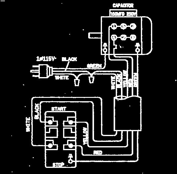

20 CIRCUIT DIAGRAM - 18-


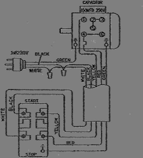
21 CIRCUIT DIAGRAM - 19-
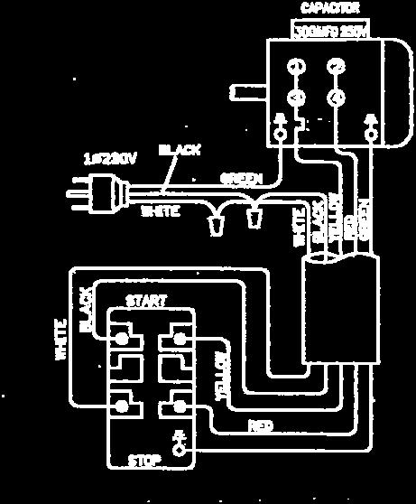
22 CIRCUIT DIAGRAM ~ - 20-
23 -21-
24 -22-
25 -23-
26 PARTS LIST MODEL NO.31 CODE NO PART NO DESCRIPTION SPECIFICATION QTY NOTE Head Body Chuck Arbor Bolt MT3 M10xP Chuck Arbor Bolt MT3 M12xP Chuck Arbor Bolt MT3 W3/8" Chuck Arbor Bolt MT3 W1/2" Chuck Arbor Bolt R8 W7/16" Chuck Arbor Bolt NT30 M12xP B Spindle Locknut A Spindle Pulley Outer Bearing Plate 105x66x2.5t 1 6 S701 Cross Round Head Screw 1/4"x1/2"L S Spindle Taper Sleeve Asbly Spindle Taper Sleeve CA6009ZZ Ball Bearing (6009ZZ) 6009ZZ Washer 74x 68x Fixed Ring 2x C-Retainer Ring 3x Rubber Flange Feed Base S Pinion Asbly MT S Pinion Asbly MT3 Heat treatment S Pinion Asbly R NS Pinion Asbly NT SS Pinion Asbly 1 Option Locknuts HI902 Washer AW CA30206J Taper Roller Bearing E30206J Rack Sleeve MT Rack Sleeve MT3 Heat treatment Rack Sleeve R CA30207J Taper Roller Bearing 30207J Spindle Shaft MT Spindle Shaft MT3 Heat treatment Spindle Shaft R Spindle Shaft NT Bearing Cap MT3\R Bearing Cap NT Punch Key Chuck Arbor MT3 M10xP Chuck Arbor MT3 M12xP Chuck Arbor MT3 W3/8" Chuck Arbor MT3 W1/2" Chuck Arbor R8 W7/16"
27 PARTS LIST MODEL NO.31 CODE NO PART NO DESCRIPTION SPECIFICATION QTY NOTE Chuck Arbor R8 7/16"-20 JT Chuck Arbor MT3 M12-B Chuck Arbor MT3 M12 B Chuck Arbor MT3 M10- B Chuck Arbor NT Cutter Arbor 25.4 M10xP Cutter Arbor 25.4 M12xP Cutter Arbor 25.4 W3/8" Cutter Arbor 25.4 W1/2" Cutter Arbor 25.4 W7/16" Cutter Arbor 27 M10xP Cutter Arbor R Cutter Arbor 27 M10xP C Cutter Arbor MT3 M D Cutter Arbor MT3 M Cutter Arbor NT S Graduated Rod Asbly Nut 1 17 S008 Hex. Head Screw 1/4"x2"L 1 18 N003 Hex. Nut 1/4" Position Set Bracket Pinion Shaft 1 21 S307 Flat Cross Head Screw 3/16"x1/2"L 1 22 HK042 Key 7x7x20L S Feed Cover Asbly Bearing Cover Worm Shaft CA6202ZZ Ball Bearing (6202ZZ) 6202ZZ HCS04 C-Retaniner Ring Washer 34x 27.5x30L 1 24 S419 Hex. Socket Head Screw 5/16"x3/4"L Worm Gear Spring Handle Base Blade Adjustable Knob Knob W/Shaft Plastic Round Knob Worm Cover 1 32 S407 Cross Round Head Screw 3/16"x3/8"L S Micro Adjusting Indicator Set Metric S Micro Adjusting Indicator Set Inch AS Handwheel Assembly S Spring Base Set
28 PARTS LIST MODEL NO.31 CODE NO PART NO DESCRIPTION SPECIFICATION QTY NOTE 38 MHP243 split pin SSP S732 Cross Round Head Screw 3/16"x3/4"L S Spring Cover Asbly 1 41 W202 Spring Washer 1/4"x1"x1.5t 1 42 W005 Washer 1/4" 1 43 W202 Spring Washer 1/4"x1"x1.5t 1 44 S471 Hex. Socket Head Screw 1/4"x5/8L Worm Shaft Bushing S Head Raise Bracket Asbly 1 48 S404 Hex. Socket Head Screw 1/4"x3/4"L S Head Handle Set S Clamp Handle A Fixed Tight Collar A Fixed Tight Collar 1 54 W002 Washer 1/2"x7/8"x2t Handle Rod Screw Key 3/8"-16UNC-38L 1 57 N005 Hex. Nut 3/8" Spring Pin Rubber Collar Head Body Fix Bolt 5/8"-150L 2 62 W019 Washer 5/8"x1-9/16"x3t 2 63 N008 Hex. Nut 5/8" Lock Handle Thumb Screw 3/8"-16UNC B Blade Adjustable Knob 3/8"-16UNC 30L 1 Option S Front Cover Plate Asbly 1 67 S701 Cross Round Head Screw 1/4"x1/2"L Limit Plate 1 69 W032 Washer 1/8" 1 70 S705 Cross Round Head Screw 1/8"x1/4"L E Belt Cover Palley Cover Shelf B Spindle Cover Palley Cover 1 75 HS801 Screw 3mm 2 76 W017 Washer 5/16" 4 77 S022 Hex. Head Screw 5/16"-18x3/4"L 4 78 S701 Cross Round Head Screw 1/4"x1/2"L 2 For CE only Speed Chart B Speed Change Inter Pulley Base 1 81 N008 Hex. Nut 5/8"
29 PARTS LIST MODEL NO.31 CODE NO PART NO DESCRIPTION SPECIFICATION QTY NOTE 82 W016 Washer 5/16"x28x3t 2 83 S019 Hex. Head Screw 5/16"x1-1/2"L AS Inter Pulley Asbly 1 85 N008 Hex. Nut 5/8" DS Motor Pulley Set 1 88 BB033 V-Belt B BB042 V-Belt B Wire Relief Retainer 1 91 S017 Hex. Head Screw 5/16"-18x1"L Motor Mount Plate 1 93 Motor 1 94 W017 Washer 5/16" 8 95 S017 Hex. Head Screw 5/16"x1"L 4 96 N007 Hex. Nut 5/16" 4 97 S025 Hex. Head Screw 7/16"x3/4"L 2 98 HK115 Key 8x7x45L Guard Bracket(For CE Only) 1 For CE only C Guard Bracket(For CE Only) 1 Option 100 HS519 Cross Round Head Screw M5x8L 2 For CE only 101 HS527 Cross Round Head Screw M6x12L 2 For CE only Protective Plate(For CE Only) 1 For CE only C Protective Plate(For CE Only) 1 Option Chuck 1/2"-JT Chuck 1/2-B Milling Cutter A Milling Cutter C Milling Cutter D Milling Cutter S Micro Switch Bracket Set 1 For CE only 116 Switch S Chuck Guard Asbly(For CE Only) 1 For CE only AS Chuck Guard Asbly(For CE Only) 1 For CE only (Option) Table Table 31L Fixed Block Movable Fixed Ring S402 Hex. Socket Head Screw 1/4"x1/2"L HB111 Oil Ball 1/4" CS Table Handle Wheel Set Table Clutch HP048 Cotter Pin 5x40L Left Flange S414 Hex. Socket Head Screw 5/16"x1"L
30 PARTS LIST MODEL NO.31 CODE NO PART NO DESCRIPTION SPECIFICATION QTY NOTE S Table Nut Set 31\31L Metric S Table Nut Set 31\31L Inch S Table Screw Asbly 31 Metric S Table Screw Asbly 31 Inch S Table Screw Asbly 31L Metric S Table Screw Asbly 31L Inch Link Screw Limit Plate HH001 Rivet Center Base Center Base 31L Antidust Plate S Antidust Plate Asbly Gib Strip Gib Strip 31L Gib Strip Movable Fixed Block S018 Hex. Head Screw 5/16"x1/2"L Gib Strip Bolt Bushing Grip Grip T Screw Thumb Screw S414 Hex. Socket Head Screw 5/16"x1"L S418 Hex. Socket Head Screw 5/16"x2-1/4"L S Acme Nut Asbly Metric S Acme Nut Asbly Inch Swivel Base S Acme Screw Asbly Metric S Acme Screw Asbly Inch Column Base Column Base Rack 600.5L Rack 885.5L S Column Head Asbly Column Flange Ring S004 Hex. Head Screw 5/8"x2-1/2"L W206 Spring Washer 5/8" S419 Hex. Socket Head Screw 5/16"x3/4"L W205 Spring Washer 5/16" HB902 Plug PT1/4" A Vise
31 -29-
32 -30-
33 -31-
34 -32-
35 -33-
36 PARTS LIST MODEL NO.31N2F CODE NO PART NO DESCRIPTION SPECIFICATION QTY NOTE Head Body Chuck Arbor Bolt MT3 M10xP Chuck Arbor Bolt MT3 M12xP Chuck Arbor Bolt MT3 W3/8" Chuck Arbor Bolt MT3 W1/2" Chuck Arbor Bolt R8 W7/16" Chuck Arbor Bolt NT30 M12xP B Spindle Locknut S Main Pulley Set A Spindle Pulley Outer Bearing Plate 105x66x2.5t 1 8 S701 Cross Round Head Screw 1/4"x1/2"L S Spindle Taper Sleeve Asbly Spindle Taper Sleeve CA6009ZZ Ball Bearing (6009ZZ) 6009ZZ Washer 74x 68x Fixed Ring 2x C-Retainer ring 3x Rubber Flange S Pinion Asbly MT S Pinion Asbly MT3 Heat treatment S Pinion Asbly R NS Pinion Asbly NT SS Pinion Asbly 1 Option Locknuts HI902 Washer AW CA30206J Taper Roller Bearing E30206J Rack Sleeve MT Rack Sleeve MT3 Heat treatment Rack Sleeve R CA30207J Taper Roller Bearing 30207J Spindle Shaft MT Spindle Shaft MT3 Heat treatment Spindle Shaft R Spindle Shaft NT Bearing Cap MT3\R Bearing Cap NT Punch Key Chuck Arbor MT3 M10xP Chuck Arbor MT3 M12xP Chuck Arbor MT3 W3/8" Chuck Arbor MT3 W1/2" Chuck Arbor R8 W7/16"
37 PARTS LIST MODEL NO.31N2F CODE NO PART NO DESCRIPTION SPECIFICATION QTY NOTE Chuck Arbor R8 7/16"-20 JT Chuck Arbor MT3 M12-B Chuck Arbor MT3 M12 B Chuck Arbor MT3 M10- B Chuck Arbor NT Cutter Arbor 25.4 M10xP Cutter Arbor 25.4 M12xP Cutter Arbor 25.4 W3/8" Cutter Arbor 25.4 W1/2" Cutter Arbor 25.4 W7/16" Cutter Arbor 27 M10xP Cutter Arbor R Cutter Arbor 27 M10xP C Cutter Arbor MT3 M D Cutter Arbor MT3 M Cutter Arbor NT S Spring Base Set 1 18 S732 Cross Round Head Screw 3/16"x3/4"L S Spring Cover Asbly 1 20 W202 Spring Washer 1/4"x1"x1.5t 2 21 W005 Washer 1/4" 1 22 S471 Hex. Socket Head Screw 1/4"x5/8L Screw Key 3/8"-16UNC-38L 1 24 N005 Hex. Nut 3/8" A Fixed Tight Collar A Fixed Tight Collar 1 27 W002 Washer 1/2"x7/8"x2t Handle Rod Spring Pin Rubber Collar Head Body Fix Bolt 5/8"-150L 2 33 W019 Washer 5/8"x1-9/16"x3t 2 34 N008 Hex. Nut 5/8" Lock Handle Thumb Screw 3/8"-16UNC Worm Shaft Bushing S Head Raise Bracket Asbly Head Raise Bracket HCS03 C-Retaniner Ring Worm Shaft 9/16"x64.3L Worm Gear
38 PARTS LIST MODEL NO.31N2F CODE NO PART NO DESCRIPTION SPECIFICATION QTY NOTE 39-5 HB111 Oil Ball 1/4" 1 40 S404 Hex. Socket Head Screw 1/4"x3/4"L S Head Handle Set S Head Asbly SA Front Cover Plate Asbly 1 45 S701 Cross Round Head Screw 1/4"x1/2"L E Belt Cover Palley Cover Shelf B Spindle Cover Palley Cover 1 50 HS801 Screw M3X5L 2 51 S022 Hex. Head Screw 5/16"-18x3/4"L 5 52 W017 Washer 5/16"X18Xt S701 Cross Round Head Screw 1/4"x1/2"L 2 For CE only Speed Chart Wire Relief Retainer 1 56 N008 Hex. Nut 5/8" B Speed Change Inter Pulley BasePalley Cover AS Inter Pulley Asbly DS Motor Pulley Set 1 61 BB033 V-Belt B BB042 V-Belt B W016 Washer 5/16" 2 64 S019 Hex. Head Screw 5/16"x1-1/2"L Guard Bracket(For CE Only) 1 For CE only C Guard Bracket(For CE Only) 1 Option 66 HS519 Cross Round Head Screw M5x8L 2 For CE only 67 HS528 Cross Round Head Screw M6x12L 2 For CE only Protective Plate(For CE Only) 1 For CE only C Protective Plate(For CE Only) 1 Option 78 Motor Motor Mount Plate 1 80 HK115 Key 8x7x45L 1 81 S017 Hex. Head Screw 5/16"x1"L 4 82 W015 Washer 5/16" 8 83 N007 Hex. Nut 5/16" 4 84 S025 Hex. Head Screw 7/16"x3/4"L S Micro Switch Bracket Set 1 For CE only S Chuck Guard Asbly(For CE Only) 1 For CE only AS Chuck Guard Asbly(For CE Only) 1 For CE only (Option) Chuck 1/2"-JT Chuck 1/2-B A Milling Cutter C Milling Cutter
39 PARTS LIST MODEL NO.31N2F CODE NO PART NO DESCRIPTION SPECIFICATION QTY NOTE 115 Switch AS Gear Box Assembly B Gear Box CA6003ZZ Bearing 6003ZZ A Change Gear Lever B Twisted Spring HP006 Pin 3x10L A Speed-Changing Key A Bushing Bracket HS421 Hex. Socker Headless Screw M6x6L A Bushing A Gear A Gear A Gear A Worm Shaft HK009 Key 5x5x25L Worm Gear HS421 Hex. Socker Headless Screw M6x6L HCR04 C-Retainer ring R Cover Speed Lever HS512 Cross Round Head Screw M4x0.7x25L Spring HB001 Steel Ball 8 or 5/16" Pin Release Block HCS08 C-Retainer ring S A Gear A Gear A Gear A Transmission Worm Shaft HK011 Key 5x5x32L A Gear Shaft HCS04 C-Retainer ring S Bushing Spring Worm Shaft HS421 Hex. Socker Headless Screw M6x6L Clutch Block CA6003ZZ Bearing 6003ZZ HK006 Key 5x5x10L A Worm Shaft HK013 Key 5x5x45L
40 PARTS LIST MODEL NO.31N2F CODE NO PART NO DESCRIPTION SPECIFICATION QTY NOTE A Worm Base W202 Spring Washer 1/4" S404 Hex. Socket Head Screw 1/4"x3/4"L HCS06 C-Retainer ring S A Gear Box Cover AS Pinion Shaft Assembly Worm Gear Cover HS605 Flat Cross Head Screw M4x4L HCS13 C-Retainer ring S Clutch Key Base Clutch Key Clutch Key Pin Spring Spring Pin Worm Gear Key A Pinion Shaft S303 Flat Cross Head Screw 3/16"x3/8"L S416 Hex. Socket Head Screw 5/16"x1-1/4"L Bearing Spacer AS Clutch Bushing Assembly Metric BS Clutch Bushing Assembly Inch A Clutch Bushing Bushing Pin Bushing Stop A Scale Base Inch B Scale Base Metric HP016 Pin Handle Body Handle Rod Pin Scale Base Set Screw Knob W/Shaft Graduated Base Fixed Grip N007 Hex. Nut 5/16" T Screw 5/16"x3/4"L S474 Hex. Socket Head Screw 5/16"x3-1/2"L Scale HH001 Rivet 2x4L Speed Scale Metric A Speed Scale Inch Worm Cover S708 Cross Round Head Screw 3/16"x3/8"L S Micro Adjusting Indicator Set Metric
41 PARTS LIST MODEL NO.31N2F CODE NO PART NO DESCRIPTION SPECIFICATION QTY NOTE AS Micro Adjusting Indicator Set Inch BS Handwheel Assembly S Sub-Pulley Set Round Belt 8x Plastic Round Knob HW016 Washer 5/16"x23x2t HS241 Hex. Socket Head Screw M8x12L Rubber Plate Table Table 31L Fixed Block Movable Fixed Ring S402 Hex. Socket Head Screw 1/4"x1/2"L HB111 Oil Ball 1/4" CS Table Handle Wheel Set Table Clutch HP048 Cotter Pin 5x40L Left Flange S414 Hex. Socket Head Screw 5/16"x1"L S Table Nut Set 31\31L Metric S Table Nut Set 31\31L Inch S Table Screw Asbly 31 Metric S Table Screw Asbly 31 Inch S Table Screw Asbly 31L Metric S Table Screw Asbly 31L Inch Link Screw Limit Plate HH001 Rivet Center Base Center Base 31L Antidust Plate S Antidust Plate Asbly Gib Strip Gib Strip 31L Gib Strip Movable Fixed Block S018 Hex. Head Screw 5/16"x1/2"L Gib Strip Bolt Bushing Grip Grip T Screw Thumb Screw
42 PARTS LIST MODEL NO.31N2F CODE NO PART NO DESCRIPTION SPECIFICATION QTY NOTE 631 S414 Hex. Socket Head Screw 5/16"x1"L S418 Hex. Socket Head Screw 5/16"x2-1/4"L S Acme Nut Asbly Metric S Acme Nut Asbly Inch Swivel Base S Acme Screw Asbly Metric S Acme Screw Asbly Inch Column Base Column Base Rack 600.5L Rack 885.5L S Column Head Asbly Column Flange Ring S004 Hex. Head Screw 5/8"x2-1/2"L W206 Spring Washer 5/8" S419 Hex. Socket Head Screw 5/16"x3/4"L W205 Spring Washer 5/16" HB902 Plug PT1/4" A Vise
43 -41-
44 -42-
45 -43-
46 PARTS LIST MODEL NO.25 CODE NO PART NO DESCRIPTION SPECIFICATION QTY NOTE Head Body Chuck Arbor Bolt MT3 M10xP Chuck Arbor Bolt M12xP Chuck Arbor Bolt W3/8" Chuck Arbor Bolt W1/2" Chuck Arbor Bolt W7/16" B Spindle Locknut B Spindle Pulley Outer Bearing Plate 84x50x2.8t 1 6 S701 Cross Round Head Screw 1/4"x1/2"L S Spindle Taper Sleeve Set Spindle Taper Sleeve CA6007ZZ Ball Bearing (6007ZZ) 6007ZZ Washer 60x 55x Retainer Ring C-Retainer ring 3x Rubber Flange S Rack Sleeve Set MT S Rack Sleeve Set R BS Rack Sleeve Set NT30 Heat treatment SS Rack Sleeve Set MT3 1 Option Locknuts HI901 Washer CA30205J Taper Roller Bearing (30205J) E30205J Rack Sleeve MT Rack Sleeve R CA30206J Taper Roller Bearing (30206J) E30206J Spindle Shaft MT Spindle Shaft R Spindle Shaft R8 Heat treatment Bearing Cap MT3\R Feed Base 1 12 S008 Hex. Head Screw 1/4"x2"L 1 13 N003 Hex. Nut 1/4" Punch Key Chuck Arbor MT3 M10xP Chuck Arbor MT3 M12xP Chuck Arbor MT3 W3/8" Chuck Arbor MT3 W1/2" Chuck Arbor R8 W7/16" Chuck Arbor R8 7/16"-20 JT Chuck Arbor MT3 M12-B Chuck Arbor NT
47 PARTS LIST MODEL NO.25 CODE NO PART NO DESCRIPTION SPECIFICATION QTY NOTE Cutter Arbor MT3 M10xP Cutter Arbor MT3 M Cutter Arbor MT3 W3/8" Cutter Arbor MT3 W1/2" Cutter Arbor R8 W7/16" N005 Hex. Nut 3/8" S Granduated Rod Set 1 19 N002 Hex. Nut 1/2" Pinion Shaft 1 21 S307 Flat Cross Head Screw 3/16"x1/2"L 1 22 HK030 Key 6x6x45L S Feed Cover Set Feed Cover Worm Shaft CA6202ZZ Ball Bearing (6202ZZ) HCS04 C-Retaniner Ring Washer Worm Cover 1 25 S708 Cross Round Head Screw 3/16"x3/8"L S Micro Adjusting Indicator Set Metric S Micro Adjusting Indicator Set Inch AS Handwheel Assembly 1 30 S419 Hex. Socket Head Screw 5/16"x3/4"L Worm Gear Spring Up-Down Handle Blade Adjustable Knob Knob W/Shaft Plastic Round Knob S Spring Base Set 1 39 S732 Cross Round Head Screw 3/16"x3/4"L S Spring&Spring Cover 1 41 W202 Spring Washer 1/4" 2 42 W005 Washer 1/4" 1 43 S471 Hex. Socket Head Screw 1/4"x5/8L Worm Shaft Bushing S Head Handle Set S Knob Worm Gear Worm Shaft Fixed Tight Collar Fixed Tight Collar
48 PARTS LIST MODEL NO.25 CODE NO PART NO DESCRIPTION SPECIFICATION QTY NOTE 53 W002 Washer 1/2"x7/8"x2t Handle Rod Screw Key 1 56 N005 Hex. Nut 3/8" Spring Pin Rubber Collar Head Body Fix Bolt 1/2"-172L 2 61 W001 Washer 1/2"x1-1/4"x3t 2 62 N001 Hex. Nut 1/2" Thumb Screw 3/8"-16UNC B Blade Adjustable Knob 3/8"-16UNC 30L 1 Option 64 Name Plate 1 65 S702 Cross Round Head Screw 1/4"x1/4"L A Belt Cover Shelf B Spindle Cover 1 69 HS801 Screw 3mm 2 70 W005 Washer 1/4" 4 71 S701 Cross Round Head Screw 1/4"x1/2"L 4 72 HS528 Cross Round Head Screw M6x12L 2 For CE only 73 Pulley Speed Chart B Speed Change Inter Pulley Base 1 75 N008 Hex. Nut 5/8" S Inter Pulley Set DS Motor Pulley Set 1 78 HB111 Oil Ball 1/4" 1 79 BA030 V-Belt A BG033 T-Belt BA038 V-Belt A W017 Washer 5/16" 2 82 S019 Hex. Head Screw 5/16"x1-1/2"L 2 83 Motor 1 84 HK029 Key 6X6X40L Motor Mount Plate 1 86 S017 Hex. Head Screw 5/16"x1"L 4 87 W033 Washer 5/16"x27mmx2t 8 88 N007 Hex. Nut 5/16" 4 89 S011 Hex. Head Screw 3/8"x1/2"L Wire Relief Retainer 1 91 S701 Cross Round Head Screw 1/4"x1/2"L Milling Cutter A Milling Cutter
49 PARTS LIST MODEL NO.25 CODE NO PART NO DESCRIPTION SPECIFICATION QTY NOTE B Milling Cutter Chuck 1/2"-JT Chuck 1/2"-B Protective Plate(For CE Only) 1 For CE only 95 HS527 Cross Round Head Screw M6x10L 2 For CE only Protective Plate(For CE Only) 1 For CE only B Protective Plate(For CE Only) 1 Option 97 HS527 Cross Round Head Screw M6x10L 2 For CE only S Micro Switch Bracket Set 1 For CE only 109 Switch S Chuck Guard Asbly(For CE Only) 1 For CE only AS Chuck Guard Asbly(For CE Only) 1 For CE only (Option) Table Fixed Block Movable Fixed Ring S402 Hex. Socket Head Screw 1/4"x1/2"L HB111 Oil Ball 1/4" CS Table Handle Wheel Set Table Clutch HP022 Pin 5x38L Left Flange S419 Hex. Socket Head Screw 5/16"x3/4"L S Table Nut Set Metric S Table Nut Set Inch S Table Screw Metric S Table Screw Inch Link Screw Limit Plate HH001 Rivet Center Base Antidust Plate S Antidust Plate Gib Strip Gib Strip Movable Fixed Block S018 Hex. Head Screw 5/16"x1/2"L Gib Strip Bolt Bushing Grip AL Grip T Screw Thumb Screw S414 Hex. Socket Head Screw 5/16"x1"L
50 PARTS LIST MODEL NO.25 CODE NO PART NO DESCRIPTION SPECIFICATION QTY NOTE 632 S418 Hex. Socket Head Screw 5/16"x2-1/4"L S Acme Nut Set Metric S Acme Nut Set Inch Swivel Base S Acme Screw Set Metric S Acme Screw Set Inch Column Base Rack S Column Head Set Column Flange Ring S421 Hex. Socket Head Screw 7/16"x2"L W215 Spring Washer 7/16" S419 Hex. Socket Head Screw 5/16"x3/4"L W205 Spring Washer 5/16" HB902 Plug PT1/4" A Vise
51 -49-
52 PARTS LIST MODEL NO. 31BS CODE NO PART NO DESCRIPTION SPECIFICATION QTY NOTE Table Table 31L Fixed Block Movable Fixed Ring S402 Hex. Socket Head Screw 1/4"x1/2"L HB111 Oil Ball 1/4" CS Table Handle Wheel Set Table Clutch HP048 Cotter Pin 5x40L A Left Flange S414 Hex. Socket Head Screw 5/16"x1"L S Table Nut Set AS Table Screw Asbly S Table Screw Asbly 31L Link Screw Limit Plate HH001 Rivet G Center Base 31 BS Center Base 31L BS Antidust Plate S Antidust Plate Asbly Gib Strip Gib Strip 31L Gib Strip Movable Fixed Block S018 Hex. Head Screw 5/16"x1/2"L Gib Strip Bolt Washer Grip Grip T Screw Thumb Screw HS233 Hex. Socket Head Screw M6x35L Bushing Acme Nut Base D Swivel Base CS Acme Screw Asbly Column Base Column Base Rack 600.5L Rack 885.5L S Column Head Asbly Column Flange Ring S004 Hex. Head Screw 5/8"x2-1/2"L W206 Spring Washer 5/8" S419 Hex. Socket Head Screw 5/16"x3/4"L W205 Spring Washer 5/16" HD103 Spring Washer PT1/4"x3/8"L Oil Hose Coupler M8x90 度 HP303 Pin N003 Hex. Nut 1/4" 2-50-
53 PARTS LIST MODEL NO. 31BS CODE NO PART NO DESCRIPTION SPECIFICATION QTY NOTE Oil Hose 6x230L Oil Hose 6x330L Oil Hose 6x140L Way Connector 6 三孔 HB501 Oil Ball 1/8" HS231 Hex. Socket Head Screw M6x25L Oil Hose Coupler PT1/8x90 度 A Vise 1-51-
54 -52-
55 PARTS LIST MODEL NO. DRO CODE NO PART NO DESCRIPTION SPECIFICATION QTY NOTE Radial Arm Cover Plum Screw 5/16'x1"L 1 4 S482 Hex. Socket Head Screw 1/2"x2-3/4"L 1 5 HB811 Nut 1/2" 1 6 W035 Washer 1/2"x 25x1.8t Radial Arm Bracket 1 8 S401 Hex. Socket Head Screw 1/4"x1"L 4 9 W037 Washer 7x 12x1.2t Dramper LCD rpm Monitor Base Fixed Plate 1 13 W036 Washer 1/2"x 25x2t 1 14 W038 Washer 1/4"x 3/4"x1.5t 1 15 HS041 Hex. Head Screw M6x55L 1 16 LS001 LCD rpm Monitor MANVK HS202 Hex. Socket Head Screw M3x10L 2 18 Binder 2 19 LS002 Scale MKT47 (B) 1 19 LS005 Scale MKT52 (L) 1 20 HW002 Washer M HS210 Hex. Socket Head Screw M4x20L A Antidust Plate A Fixed Bracket 1 24 S475 Hex. Socket Head Screw 1/4"x1-1/4"L B Arm 1 26 HT008 Round Head Screw 1/4"x1"L 2 27 HT007 Round Head Screw 1/4"x3/4"L A Plate A Movable Base 1 30 HD504 Hex. Socket Head Screw 3/16"x5/8"L 2 31 HS210 Hex. Socket Head Screw M4x20L 4 32 HW002 Washer M HS215 Hex. Socket Head Screw M4x45L D Base 2 35 S603 Hex. Socker Headless Screw 1/4"x3/4"L 2 36 S604 Hex. Socker Headless Screw 1/4'x3/8"L 2 37 LS003 Scale MKT
56 MANUFACTURER: ADDRESS: SERIAL No.: PLEASE WRITE DOWN THE SERIAL NO. ON THIS BLOCK FROM THE NAME PLATE AFTER YOU RECEIVE THIS MACHINE.
MILLING \ DRILLING MACHINE
 MILLING \ DRILLING MACHINE MODEL 400HS/400S2F 400HC/400C2F 400-070620-R2 INSTRUCTION MANUAL ! WARNING! Some dust created by power sanding, sawing, grinding, drilling, and other construction activities
(PARTS LIST) MODEL: MD-20/25 Mill / Drill Bench Machine
 MODEL: MD-20/25 Mill / Drill Bench Machine") OPERATION MANUAL (PARTS LIST) MODEL: MD-20/25 Mill / Drill Bench Machine TRUPRO-TEC Industrial Ltd. No.90, Alley22,Lane 428, Sec. 1, Fong Yuan Blvd. Fong Yuan Dist. Taichung City, Taiwan, ROC Tel. 886-4-25358299(Rep)
OPERATION MANUAL (PARTS LIST) MODEL: MD-20/25 Mill / Drill Bench Machine TRUPRO-TEC Industrial Ltd. No.90, Alley22,Lane 428, Sec. 1, Fong Yuan Blvd. Fong Yuan Dist. Taichung City, Taiwan, ROC Tel. 886-4-25358299(Rep)
01950 Heavy Duty Floor Standing Morticer with Cabinet
 Please dispose of packaging for the product in a responsible manner. It is suitable for recycling. Help to protect the environment, take the packaging to the local amenity tip and place into the appropriate
D R I L L - G R I N D E R S BL 13D-2
 D R I L L - G R I N D E R S BL 13D-2 2 Table of contents 1. General safety rules for all machines 3 2. Additional safety rules 4 3. Features 4 4. Specification 4 5. Operation 4 5.1 Assemble the fixture
MI MI OPERATING MANUAL
 MODEL NO.: MI-76100 MI-76150 OPERATING MANUAL RULES for SAFE OPERATION MAGNUM INDUSTRIAL MI-76100 and MI 76150 DRILL PRESSES To help ensure safe operation, please take a moment to learn the how to operate
Trajan 812G Cut Off Saw Parts and Service Manual Order Parts From
 www.trajansaw.com Trajan 812G Cut Off Saw Parts and Service Manual Order Parts From www.bandsawparts.com 713-884-1101 1 195006B Base 1 2S 195016ES Stand Complete Assembly 1 2-1 195016E Coolant Pan 1 2-2
VARIABLE SPEED WOOD LATHE
 MODEL MC1100B VARIABLE SPEED WOOD LATHE INSTRUCTION MANUAL Please read and fully understand the instructions in this manual before operation. Keep this manual safe for future reference. Version: 2015.02.02
PARTS. W1669 & W1670 Parts PARTS. Model W1669/W1670 (For Machines Mfd. Since 04/18) 66V A A A 28A
 66V A A A 28A") W1669 & W1670 Parts 23 66V2 22 21 25 26 53A 62 63 89 64 9 65 24 20 15 16A 54 93 10 16A-1 81 77 94 53 79 102 103 28 36 8 30 19 31 32 32-1 109 28A 28 27 34 33 56 49 76 76 19-3 19-1 19-2 38-1 89 35 60 59
W1669 & W1670 Parts 23 66V2 22 21 25 26 53A 62 63 89 64 9 65 24 20 15 16A 54 93 10 16A-1 81 77 94 53 79 102 103 28 36 8 30 19 31 32 32-1 109 28A 28 27 34 33 56 49 76 76 19-3 19-1 19-2 38-1 89 35 60 59
WARNING! Read and understand the entire instruction manual before attempting set-up or operation of this machine!
 ! WARNING! Read and understand the entire instruction manual before attempting set-up or operation of this machine! 1. This machine is designed and intended for use by properly trained and experienced
Trajan 1319ADR Fabricating Saw Parts and Service Manual Order Parts From
 www.trajansaw.com Trajan 1319ADR Fabricating Saw Parts and Service Manual Order Parts From www.bandsawparts.com 713-884-1101 CODE_NO PART_NO DESCRIPTION SPECIFICATION QTY 1S 103005AS Stand 1.00 2 103009
TB & SB Series Drill Presses
 TB & SB Series Drill Presses OWNERS MANUAL BENCH AND FLOOR DRILL PRESS TB-16 Series & SB-16-25-32-Series FOR YOUR OWN SAFETY AND OPTIMUM OPERATION READ INSTRUCTION MANUAL BEFORE OPERATING DRILL PRESS RETAIN
VARIABLE SPEED WOOD LATHE. Model DB900 INSTRUCTION MANUAL
 VARIABLE SPEED WOOD LATHE Model DB900 INSTRUCTION MANUAL 1007 TABLE OF CONTENTS SECTION...PAGE Technical data.. 1 General safety rules....1-3 Specific safety rules for wood lathe.....3 Electrical information.4
MANUAL KEF SB 30/35 and 40 Geared Head Drilling Machines
 Industrivej 3-9 DK-9460 Brovst Denmark Tlf.: +45 9823 6088 Fax.: +45 9823 6144 MANUAL KEF SB 30/35 and 40 Geared Head Drilling Machines EC declaration of conformity KEF-MOTOR A/S Industrivej 3-9 DK-9460
GEARED HEAD DRILL / MILL MACHINE INSTRUCTION MANUAL
 www.industrialtool.com.au GEARED HEAD DRILL / MILL MACHINE INSTRUCTION MANUAL READ CAREFULLY AND UNDERSTAND THESE INSTRUCTIONS BEFORE USE. LIMITED WARRANTY Industrial Tool & Machinery Sales (hereinafter
Horizontal and Vertical. Metal Cutting Band Saw MODEL: BS-115
 Horizontal and Vertical Metal Cutting Band Saw MODEL: BS-5 SAFETY. Know your band saw. Read the operator s Manual carefully. Learn the operations, applications and limitation.. Use recommended accessories.
SECTION 9: PARTS Main Breakdown
 SECTION 9: PARTS Main Breakdown 2 115 75 113 112 8 9 7 8 11 4 5 3 3 85 81 79 78 90 84 68 69 69 68 87 86 86 91 95 98-2 98-1 98-3 98-4 98 98-8 98-9 98-5 98-6 99 97 98-7 100 92 114 108 107 110 109 111 104
& Drill Press Owner s Manual
 10060.001 & 10061.0001 Drill Press Owner s Manual Oliver Machinery M-10060/61 11/2018 Seattle, WA Copyright 2003-2018 info@olivermachinery.net www.olivermachinery.net SAFETY INSTRUCTION READ BEFORE OPERATION
Assembly Instructions and Parts Manual 5C Collet Closer for GHW Lathes Model CC-GHW
 Assembly Instructions and Parts Manual 5C Collet Closer for GHW Lathes Model CC-GHW JET 427 New Sanford Road LaVergne, Tennessee 37086 Part No. M-321519 Ph.: 800-274-6848 Revision G1 03/2014 www.jettools.com
Assembly Instructions and Parts Manual 5C Collet Closer for ZX Series Lathes Model CC-ZX
 Assembly Instructions and Parts Manual 5C Collet Closer for ZX Series Lathes Model CC-ZX JET 427 New Sanford Road LaVergne, Tennessee 37086 Part No. M-321292 Ph.: 800-274-6848 Revision B 03/2014 www.jettools.com
SB-32V Drill Press OWNERS MANUAL
 724 Robbins Road, Grand Haven, MI 49417 Phone: 616-842-7110 800-937-3253 Fax: 616-842-0859 800-846-3253 Web: www.dakecorp.com E-mail: customerservice@dakecorp.com SB-32V Drill Press OWNERS MANUAL FOR YOUR
SECTION 9: PARTS. G7947 Stand & Table Breakdown 4V2
 SECTION 9: PARTS G7947 Stand & Table Breakdown 19 15 21 18 16 17 112 5 113 3 14 8 7 6 6-1 13 4V2 12 116 11 9 10 2 114 115 1 We do our best to stock replacement parts when possible, but we cannot guarantee
SECTION 9: PARTS G7945/G7946
 SECTION 9: PARTS G7945/G7946 Main Parts 22 53 25 26 31 139 32 32-1 60 38 59 38-1 119 35 37 31 38-3 124 125 45A-2 45A-4 45A-1 31 60 45A-3V2 120 121 62 28 28-1 28 27 34 50 51 39 41 126 137 36 46 40 63 33
ROTARY HAMMER OWNER S MANUAL
 ROTARY HAMMER OWNER S MANUAL WARNING: Read carefully and understand all ASSEMBLY AND OPERATION INSTRUCTIONS before operating. Failure to follow the safety rules and other basic safety precautions may result
# R8 Mill Instruction Manual. Please read and understand all instructions before using this tool.
 #8460 R8 Mill Instruction Manual Please read and understand all instructions before using this tool. Note: These instructions will show you how to assemble this machine, work its controls and maintain
ZA40 ZA45 MILLING& DRILLING MACHINE OPERATING MANUAL
 ZA40 ZA45 MILLING& DRILLING MACHINE OPERATING MANUAL CONTENTS 1.SPECIFICATION---------------------------------3 2.FEATURES--------------------------------------5 3.MOUNTING MACHINE------------------------------5
SECTION 9: PARTS. Headstock
 SECTION 9: PARTS We do our best to stock replacement parts when possible, but we cannot guarantee that all parts shown are available for purchase. Call (800) 52-4777 or visit www.grizzly.com/parts to check
Drill Press Owner s Manual
 10062.0001 Drill Press Owner s Manual Oliver Machinery M-10062 11/2018 Seattle, WA Copyright 2003-2018 info@olivermachinery.net www.olivermachinery.net SAFETY INSTRUCTION READ BEFORE OPERATION To help
FOR YOUR SAFETY: READ ALL INSTRUCTIONS CAREFULLY
 MODEL 2020F FOR YOUR SAFETY: READ ALL INSTRUCTIONS CAREFULLY Table of Contents General safety instructions for Power Tools 1 Main specification 2 Unpacking and checking contents 2 List of loose parts in
ZX45A POWER FEED BENCH MILLING&DRILLING MACHINE OPERATING MANUAL
 ZX45A POWER FEED BENCH MILLING&DRILLING MACHINE OPERATING MANUAL CONTENTS SAFETY WARNING---------------------------3 SPECIFICATION----------------------------4 FEATURES---------------------------------5
ELECTRIC SLIP ROLL MACHINE. Model: ESR-1300X2.5/ESR-1300X4.5 ESR-1550X3.5/ESR-1580X2.0
 ELECTRIC SLIP ROLL MACHINE Model: ESR-1300X2.5/ESR-1300X4.5 ESR-1550X3.5/ESR-1580X2.0 Operation Manual Table of contents I MAIN SPECIFICATION...2 II SAFETY INSTRUCTIONS.. 2 III OPERATION INSTRUCTIONS..4
Operating Instructions and Parts Manual SR-2024M and SR-2236M Slip Rolls
 Operating Instructions and Parts Manual SR-2024M and SR-2236M Slip Rolls JET 427 New Sanford Road LaVergne, Tennessee 37086 Part No. M-756020 Revision A1 05/2014 Copyright 2014 JET Warranty and Service
EllisSaw.com. EllisSaw.com P.O. Box Verona, WI
 P.O. Box 9019 Verona, WI 9-019 GENERAL OPERATING & SAFETY INSTRUCTIONS * READ INSTRUCTIONS BEFORE USE * CAUTION: Disconnect power supply cord from power source when doing repair work or changing belt.
12mm (Max) 6mm (Max) 82mm (Max) 12mm (Max) 6mm (Max)
 6mm (Max) 82mm (Max) 12mm (Max) 6mm (Max)") 1 1 2 2 3 3 82mm (Max) 12mm (Max) 12mm (Max) 6mm (Max) 4 4 5 6 8 6mm (Max) 0.5 0mm 1 5 6 7 7 8 9 9 A = B 10 11 12 D B 1 13 14 15 0 C A D E 16 17 18 F G D B N H J G I K 19 A 20 G L 21 C K 1mm L M 1mm 22
1 1 2 2 3 3 82mm (Max) 12mm (Max) 12mm (Max) 6mm (Max) 4 4 5 6 8 6mm (Max) 0.5 0mm 1 5 6 7 7 8 9 9 A = B 10 11 12 D B 1 13 14 15 0 C A D E 16 17 18 F G D B N H J G I K 19 A 20 G L 21 C K 1mm L M 1mm 22
HAMMER DRILL OWNER S MANUAL
 HAMMER DRILL OWNER S MANUAL WARNING: Read carefully and understand all ASSEMBLY AND OPERATION INSTRUCTIONS before operating. Failure to follow the safety rules and other basic safety precautions may result
Assembly Instructions and Parts Manual Taper Attachment for Bench Lathes Model TAK-13GH/BD
 Assembly Instructions and Parts Manual Taper Attachment for Bench Lathes Model TAK-13GH/BD JET 427 New Sanford Road LaVergne, Tennessee 37086 Part No. M-321442 Ph.: 800-274-6848 Revision B 03/2014 www.jettools.com
ZA32G ZA40G ZA45G BENCH MILLING&DRILLING MACHINE OPERATING MANUAL
 ZA32G ZA40G ZA45G BENCH MILLING&DRILLING MACHINE OPERATING MANUAL CONTENTS SAFETY WARNING---------------------------3 SPECIFICATION----------------------------4 FEATURES---------------------------------5
GENERAL OPERATIONAL PRECAUTIONS PRECAUTIONS ON USING CUT-OFF MACHINE
 GENERAL OPERATIONAL PRECAUTIONS WARNING! When using electric tools, basic safety precautions should always be followed to reduce the risk of fire, electric shock and personal injury, including the following.
Read carefully and follow all safety rules and operating instructions before first use of this product.
 operating manual & parts list 80161 & 70104 MILL DRILL AND STAND Read carefully and follow all safety rules and operating instructions before first use of this product. 2095.09-050 Palmgren Operating Manual
HOLE CUTTER SHARPENER ASSEMBLY & SERVICE MANUAL
 HOLE CUTTER SHARPENER ASSEMBLY & SERVICE MANUAL WARNING You must thoroughly read and understand this manual before operating the equipment, paying particular attention to the Warning & Safety instructions.
Variable Speed Cast Iron Midi Wood Lathe
 01936 Variable Speed Cast Iron Midi Wood Lathe Please read and fully understand the instructions in this manual before operation. Keep this manual safe for future reference. 1 Technical Data Input voltage
THIS ACCESSORY CAN ONLY BE USED ON THE
 Instruction Manual NOVA COMET II STAND THIS MANUAL CONTAINS IMPORTANT INFORMATION REGARDING SAFETY, OPERATION, MAINTENANCE AND STORAGE OF THIS PRODUCT. BEFORE USE, READ CAREFULLY AND UNDERSTAND ALL CAUTIONS,
MODEL NO.: MI PARTS BREAKDOWN
 MODEL NO.: MI-76350 PARTS BREAKDOWN MAGNUM DRILL PRESS ASSEMBLY INSTRUCTIONS MODEL MI-76350 Before you begin to assemble your drill press, review the parts breakdown and keep it ready for reference. Start
Operating Instructions and Parts Manual. 10 x 16 Horizontal Band Saw Models J-7020, J-7040
 Operating Instructions and Parts Manual 10 x 16 Horizontal Band Saw Models J-7020, J-7040 JET 427 New Sanford Road LaVergne, Tennessee 37086 Part No. M-414472 Ph.: 800-274-6848 Revision C2 03/2014 www.jettools.com
Operating Instructions and Parts Manual Foot Shear Models: FS-1636H, FS-1652H
 Operating Instructions and Parts Manual Foot Shear Models: FS-1636H, FS-1652H JET 427 New Sanford Road LaVergne, Tennessee 37086 Part No. M-752636 Ph.: 800-274-6848 Revision B2 08/2014 www.jettools.com
L A M I N AT E F L O O R C U T T E R OWNER S MANUAL
 L A M I N AT E F L O O R C U T T E R OWNER S MANUAL WARNING: Read carefully and understand all INSTRUCTIONS before operating. Failure to follow the safety rules and other basic safety precautions may result
17 Floor Drill Press. Operator s Manual. Record the serial number and date of purchase in your manual for future reference.
 30-230 17 Floor Drill Press Operator s Manual Record the serial number and date of purchase in your manual for future reference. Serial Number: Date of purchase: For technical support or parts questions,
BB Inch Double Cut Saw Assembly & Operating Instructions READ ALL INSTRUCTIONS AND WARNINGS BEFORE USING THIS PRODUCT.
 BB07552 5 Inch Double Cut Saw Assembly & Operating Instructions READ ALL INSTRUCTIONS AND WARNINGS BEFORE USING THIS PRODUCT. This manual provides important information on proper operation & maintenance.
Hinge Boring/Insertion Machine Set Up And Operation Instructions
 Hinge Boring/Insertion Machine Set Up And Operation Instructions Manufactured In The USA By: Thompson Industries, Inc. 1018 Crosby Avenue, Sycamore, IL. 60178-0127 Ph:815-899-6670 Fax:815-899-1918 Thank
VARIABLE SPEED BECH LATHE
 VARIABLE SPEED BECH LATHE Instruction Manual Please read this instruction manual thoroughly and follow all directions carefully. 1 Important Safety Instructions READ ALL INSTRUCTIONS AND WATNINGS BEFORE
Operating Instructions and Parts Manual JMD-15/18/18PFN Mill/Drill Machine
 Operating Instructions and Parts Manual JMD-15/18/18PFN Mill/Drill Machine (JMD-18 shown with optional CS-18 stand) JET 427 New Sanford Road LaVergne, Tennessee 37086 Part No. M-350020 Ph.: 800-274-6848
Operating Instructions and Parts Manual 5C Collet Closer for GHB-1340A Lathe Model CC-GHB1340A
 Operating Instructions and Parts Manual 5C Collet Closer for GHB-1340A Lathe Model CC-GHB1340A JET 427 New Sanford Road LaVergne, Tennessee 37086 Part No. M-321514A Ph.: 800-274-6848 Revision C 03/2014
1 HP Dust Collector. Operator s Manual. Record the serial number and date of purchase in your manual for future reference.
 Model: 60-100 1 HP Dust Collector Operator s Manual Record the serial number and date of purchase in your manual for future reference. Serial Number: Date of purchase: For technical support or parts questions,
HAND HELD SAW W MILL
 HAND HELD SAW W MILL 92247 ASSEMBLY AND OPERATING INSTRUCTIONS 3491 Mission Oaks Blvd., Camarillo, CA 93011 Visit our Web site at http://www.harborfreight.com Copyright 2004 by Harbor Freight Tools. All
OPERATORS MANUAL. Band Saw by. Model SFI-60. (877) East (800) West
 East (800) West") OPERATORS MANUAL Band Saw by INVICTA Model SFI-60 INVICTA USA (877) 308-6423 - East (800) 499-4682 - West English Version General Instructions Thank you for purchasing this quality machine from INVICTA.
OPERATORS MANUAL Band Saw by INVICTA Model SFI-60 INVICTA USA (877) 308-6423 - East (800) 499-4682 - West English Version General Instructions Thank you for purchasing this quality machine from INVICTA.
12. Mechanical Drawings & Parts Breakdown List
 12. Mechanical Drawings & Parts Breakdown List Note: When ordering parts, please be prepared with, 1. Machine model & serial number. 2. Item number. 3. Part number and description. 4. Year of Production.
x 43 Wood Lathe
 Please dispose of packaging for the product in a responsible manner. It is suitable for recycling. Help to protect the environment, take the packaging to the local amenity tip and place into the appropriate
Instructions for Stone Cutting Machine
 Technical data Kg. Instructions for Stone Cutting Machine SCM600 3HP 2800rpm IP55 SCM800 3HP 2800rpm IP55 SCM1000 2800rpm IP55 SCM1200 2800rpm IP55 L=600 B=85(165) L=800 B=85(175) 500x510 0 or 45 600lt/h
Ellis Drill Press Model 9400
 Ellis Drill Press Model 9400 Instruction Manual POWER FEED DRILL PRESS Infinitely Variable Speed Model 9400 Operation Manual February 17, 2006 CONTENTS Page Number Preface 2 Installation Instruction 2
 GENERAL OPERATIONAL PRECAUTIONS WARNING! When using electric tools, basic safety precautions should always be followed to reduce the risk of fire, electric shock and personal injury, including the following.
OPERATOR S MANUAL BENCH LATHE MODEL: BT1337G BOLTON TOOLS 1136 SAMUELSON ST. CITY OF INDUSTRY, CA 91748
 OPERATOR S MANUAL BENCH LATHE MODEL: BT1337G BOLTON TOOLS 1136 SAMUELSON ST. CITY OF INDUSTRY, CA 91748 Many thanks for purchasing our BT1337G - Bench Lathe. Before operating, make sure you study the manual
Tapping Screw (W/Flange) 46 Cord Armor 47 Tube (D) 48 Cord. 45 Cord Clip. Tapping Screw (W/Flange) 10 Gear Cover Ass'y. 12 Socket (B) Ass'y
 46 Cord Armor 47 Tube (D) 48 Cord. 45 Cord Clip. Tapping Screw (W/Flange) 10 Gear Cover Ass'y. 12 Socket (B) Ass'y") W8VB The exploded assembly drawing should be used only for authoized service center. W8VB Item No. Part time 1 Magnetic Hex. Socket 2 Sub Stopper 3 O-Ring (S-16) 4 Locator (A) 5 Lock Sleeve (A) 6 O-Ring
W8VB The exploded assembly drawing should be used only for authoized service center. W8VB Item No. Part time 1 Magnetic Hex. Socket 2 Sub Stopper 3 O-Ring (S-16) 4 Locator (A) 5 Lock Sleeve (A) 6 O-Ring
SECTION 9: PARTS Column Breakdown
 SECTION 9: PARTS Column Breakdown 3 4 5 6 7 8 12 2 1 9 10 11 20 21 13 14 15 18 16 17 25 26 27 28 29 3 31 31-1 32 33 34 35 36 37 39 38 47 48 46 45 3644 44 43 40 41 42 24 23 22 52 51 50 30 49 57 58 59 60
Electric Router. Please read and fully understand the instructions in this manual before operation and keep this manual safe for future
 Electric Router FOR HELP OR ADVISE ON THIS PRODUCT PLEASE CALL OUR CUSTOMER SERVICE HELP LINE : 0509 500400 THE MANUFACTURER RESERVES THE RIGHT TO ALTER THE DESIGN OR SPECIFICATION TO THIS PRODUCT WITHOUT
Twist Drill Grinder. Operation Manual. Model : GS-21 / GS-34
 Twist Drill Grinder Operation Manual Model : GS-21 / GS-34 RECYCLING Do not dispose of electrical appliances as unsorted municipal waste, use separate collection facilities. Contact your local government
Trajan 20 Cut Off Saw Parts and Service Manual Order Parts From
 www.trajansaw.com Trajan 20 Cut Off Saw Parts and Service Manual Order Parts From www.bandsawparts.com 713-884-1101 Parts List Page 1 CODE_NO PART_NO DESCRIPTION SPECIFICATION QTY 1A 133062A Swivel Arm
PS /8 Inch Electric Drill Assembly & Operating Instructions
 PS07216 3/8 Inch Electric Drill Assembly & Operating Instructions READ ALL INSTRUCTIONS AND WARNINGS BEFORE USING THIS PRODUCT. This manual provides important information on proper operation & maintenance.
Twist Drill Grinder. Operation Manual. Model : GS-20
 Twist Drill Grinder Operation Manual Model : GS-20 RECYCLING Do not dispose of electrical appliances as unsorted municipal waste, use separate collection facilities. Contact your local government for information
11. PARTS LIST 11.1 HEAD STOCK UPSIDE (1) 11-1
 11-1") 11. PARTS LIST 11.1 HEAD STOCK UPSIDE (1) 11-1 HEAD STOCK UPSIDE (1) PARTS LIST NO. PART NO DESCRIPTION QTY 1. SC-M6x20L SOCKET CAP SCREW 4 2. K6-K042-00 TOP BEARING CAP 1 3. 6009LLB BALL BEARING 1 4.
11. PARTS LIST 11.1 HEAD STOCK UPSIDE (1) 11-1 HEAD STOCK UPSIDE (1) PARTS LIST NO. PART NO DESCRIPTION QTY 1. SC-M6x20L SOCKET CAP SCREW 4 2. K6-K042-00 TOP BEARING CAP 1 3. 6009LLB BALL BEARING 1 4.
OPERATING INSTRUCTIONS AND PARTS LISTS
 3889560 REEL ALIGNMENT GAGE OPERATING INSTRUCTIONS AND PARTS LISTS WARNING You must thoroughly read and understand this manual before operating the equipment, paying particular attention to the Warning
12 Slip Roll. Model Assembly & Operating Instructions
 12 Slip Roll Model 36698 Assembly & Operating Instructions Diagrams within this manual may not be drawn proportionally. Due to continuing improvements, actual product may differ slightly from the product
Operating Instructions and Parts Manual SR-1650M Slip Roll
 Operating Instructions and Parts Manual SR-1650M Slip Roll WALTER MEIER (Manufacturing) Inc. 427 New Sanford Road LaVergne, Tennessee 37086 Part No. M-756050 Ph.: 800-274-6848 Revision A 12/2010 www.waltermeier.com
TurncrafterPlus. Variable Speed Mini Wood Lathe. User s Manual #TCLPLUS PRODUCT NO.
 TurncrafterPlus Variable Speed Mini Wood Lathe PRODUCT NO. #TCLPLUS User s Manual SPECIFICATIONS OF TURNCRAFTER PLUS MINI LATHE Model number:..............................................#tclplus Motor:......................................0V
PLATINUM SERIES TABLESAW W/DOVETAIL MECH LEFT-TILT MANUAL
 PLATINUM SERIES TABLESAW W/DOVETAIL MECH LEFT-TILT MANUAL LAGUNA TOOLS 2072 Alton Parkway Irvine, California 92606 Ph: 800.234.1976 www.lagunatools.com 2018, Laguna Tools, Inc. LAGUNA and the LAGUNA Logo
Cyclone Upcut Cut off saw
 Cyclone Upcut Cut off saw Operation manual WARNING The operator must thoroughly read and understand this manual before operating the cut off saw or starting any servicing. All safety and warning instructions
10 BANDSAW OPERATING INSTRUCTIONS MODEL: W715
 Machinery & Tooling at its best! 10 BANDSAW OPERATING INSTRUCTIONS MODEL: W715 Charnwood, Cedar Court, Walker Road, Bardon, Leicestershire, LE67 1TU Tel. 01530 516926 Fax. 01530 516929 email; sales@charnwood.net
SERIES I MILLING MACHINES
 INSTALLATION, OPERATION, MAINTENANCE, AND PARTS LIST SERIES I MILLING MACHINES TP5260 Revised: August 29, 2005 Manual No. M-450 Litho in U.S.A. Part No. M -0009500-0450 June, 2003 MAINTENANCE PROCEDURES
24" x 24" OSCILLATING SPINDLE MANUAL
 24" x 24" OSCILLATING SPINDLE MANUAL LAGUNA TOOLS 2072 Alton Parkway Irvine, California 92606 Ph: 800.234.1976 www.lagunatools.com 2018, Laguna Tools, Inc. LAGUNA and the LAGUNA Logo are the registered
V BELT DRIVEN DRILLING MACHINES HU 16-2 TOPLINE HU 16-4 TOPLINE
 V BELT DRIVEN DRILLING MACHINES HU 16-2 TOPLINE HU 16-4 TOPLINE 1 2 4 3 5 Fig. A - Main parts Fig. 1 Fig. 3 Fig. 2 2 CHANGES AND TYPING ERRORS RESERVED Fig. 4 Fig. 5 Fig. 7 Fig. 6 Fig. 8 Fig. 9 CHANGES
BENCH GRINDER OWNER S MANUAL
 BENCH GRINDER OWNER S MANUAL WARNING: Read carefully and understand all ASSEMBLY AND OPERATION INSTRUCTIONS before operating. Failure to follow the safety rules and other basic safety precautions may result
Grizzly Drill Press SOP
 Grizzly Drill Press SOP Drill Press is wired to run on 0V. Drill Press has a built in light with a ON/OFF switch. Never hold a workpiece by hand while drilling. Clamp it down or hold it in a vice. Never
MODEL G0760 8" X 29" MILL/DRILL w/stand & POWER FEED MANUAL INSERT
 MODEL G0760 8" X 29" MILL/DRILL w/stand & POWER FEED MANUAL INSERT The Model G0760 is the same machine as the Model G0705 except the Model G0760 has an X-axis table power feed. Except for the differences
30DC Speed Lathe Manual
 30DC Speed Lathe Manual The Crozier Model 30DC Speed Lathe is our most popular model. It has many standard features not found on any other machine in its class or price range. Standard Features 3/4 HP
OWNER'S MANUAL JST-48 Sliding Table
 OWNER'S MANUAL JST-48 Sliding Table (shown mounted on JET 708663PK) JET EQUIPMENT & TOOLS, INC. P.O. BOX 1349 Phone:253-351-6000 A WMH Company Auburn, WA 98071-1349 Fax: 1-800-274-6840 www.jettools.com
SALES CUSTOMER SERVICE TECHNICAL ASSISTANCE CALL TOLL-FREE:
 DENTAL, INC. TECHNICAL BULLETIN U802-022510 5860 FLYNN CREEK ROAD READ ALL INSTRUCTIONS P.O. BOX 106 BEFORE PROCEEDING COMPTCHE, CALIFORNIA, U.S.A. 95427 SAVE THIS FOR FUTURE REFERENCE THIS PRODUCT IS
20 Log Splitter (Model C)
") INSTRUCTION MANUAL 20 Log Splitter (Model 38-610C) Dated 12-15-01 Part No. 1235600 Copyright 2001 Delta Machinery A Pentair Company To learn more about DELTA MACHINERY visit our website at: www.deltamachinery.com.
INSTRUCTION MANUAL 20 Log Splitter (Model 38-610C) Dated 12-15-01 Part No. 1235600 Copyright 2001 Delta Machinery A Pentair Company To learn more about DELTA MACHINERY visit our website at: www.deltamachinery.com.
ELECTRIC TUBE ROLLER
 41238-0000 ELECTRIC TUBE ROLLER OPERATING INSTRUCTIONS & SERVICE MANUAL Rev: A, 8/20/2007 TO REDUCE THE RISK OF INJURY AND EQUIPMENT DAMAGE USER MUST READ AND UNDERSTAND OPERATOR S MANUAL. Thomas C. Wilson,
OWNER'S MANUAL HN-16T Hand Notcher
 OWNER'S MANUAL HN-16T Hand Notcher WALTER MEIER (Manufacturing) Inc. 427 New Sanford Road LaVergne, Tennessee 37086 Part No. M-756016 Ph.: 800-274-6848 Revision A 04/2011 www.waltermeier.com Copyright
SECTION 9: PARTS. Headstock A 126A 127A-1 REF PART # DESCRIPTION REF PART # DESCRIPTION
 SECTION 9: PARTS Headstock 120 121 113 115 112 111 110 109 108 105 106 107 135 101 119A 121 120 118 114 115 107 106 104 123 122 118 114 126A 105 126 103 102 126B 127A-1 131 127A 124 133 134 126C 129 130
SAFETY AND OPERATING MANUAL
 SAFETY AND OPERATING MANUAL BladeRunner X2 WX572 9 10 8 11 5 7 12 6 20 1 2 4 3 14 13 15 A2 A1 17 18 B2 B1 1 2 1 2 19 B3 3 4 2 C 1 D1 D1 C 2 1 E1 D2 1 2 E2 1 2 F G1 G1 F OFF ON G2 G3 H1 H2 I1 I2 I1 I2 J
ROUND BENDING MACHINE Model: RBM30
 ROUND BENDING MACHINE Model: RBM30 Operation Manual SAVE THIS MANUAL:You will need the manual for the safety warnings and precautions, assembly instructions, operating and maintenance procedures, parts
ST1007/ST1012 PARTS ST1007
 ST1007/ST1012 PARTS ST1007 Main Breakdown 30-7 30-8 30-10 30-9 30-1 30-3 30-6 30-2 30-4 30-5 82 83 84 77 78 79 80 30 60 59 58 62 64 61 46 44 63 66 65 55 56 26 45 27 45 27 25 43 37 41 50 42 72 73 51 53
INSTRUCTION BOOK AND PARTS LIST
 Rag Cutter MODEL WE WARNING This machine is equipped with a very sharp knife. Keep hands, arms, and hair away from the knife area at all times. Misuse of this machine or failure to follow all safety instructions
1/4 Sheet Palm Sander
 OWNER S MANUAL Model Number: PS160CA-3 1/4 Sheet Palm Sander TM Registration Card Inside CAUTION! To reduce the risk of fire, electric shock and personal injury, read and understand the owner s manual
Model W1854 (For Machines Mfd. Since 02/18) PARTS. Main Breakdown 42-1 PARTS -46-
 PARTS. Main Breakdown 42-1 PARTS -46-") 3 144 1 143 119 1 4-1 14 140 13 4 1 1 4 14 11 7 108 134 131 13 14 100 1 8 16 9 80 93 40 14 146 39 Main Breakdown 133 117 130 10 3 19 3 11 10 9 38 9 7 6 4 13 7 134 16 138 141 Model W184 (For Machines Mfd.
3 144 1 143 119 1 4-1 14 140 13 4 1 1 4 14 11 7 108 134 131 13 14 100 1 8 16 9 80 93 40 14 146 39 Main Breakdown 133 117 130 10 3 19 3 11 10 9 38 9 7 6 4 13 7 134 16 138 141 Model W184 (For Machines Mfd.
SECTION 9: PARTS. Table & Column Breakdown
 SECTION 9: PARTS Table & Column Breakdown Table & Column Parts List 201 P1126201 TABLE HANDWHEEL 230 P1005603 LIMIT STOP SLEEVE 205 P1126205 LEADSCREW ASSY M23.5-2.5 X 468 2121 P11262121 INDICATOR PLATE
AC9950. WARNING To reduce the risk of injury, the user must read and understand the operator s manual before using this product.
 OPERATOR S MANUAL Herc-u-Lift PLUS TM Adjustable Frame Caster Set AC9950 For Use With These Ridgid Products: TS2412/ TS2424 Table Saw, BS1400 Band Saw, RS1000 Radial Arm Saw, TP1300LS Thickness Planer,
PLATE JOINER 4 INCH. ASSEMBLY and OPERATING INSTRUCTIONS. Distributed Exclusively by Harbor Freight Tools
 PLATE JOINER 4 INCH 38437 ASSEMBLY and OPERATING INSTRUCTIONS Distributed Exclusively by Harbor Freight Tools 3491 Mission Oaks Blvd., Camarillo, CA 93011 Copyright 1998 by Harbor Freight Tools. All rights
Model W1837 (For Machines Mfd. Since 8/18) PARTS. Main PARTS -83-
 PARTS. Main PARTS -83-") -83- Main 29 30 31 34 35 36 37 38 39 40 41 42 43 44 45 46 47 48 49 50 51 52 53 54 55 56 57 58 61 62 63 64 65 66 67 68 69 70 71 72 73 74 75 113 96 90 91 92 93 95 96 97 98 100 101 102 103 104 105 106 109
-83- Main 29 30 31 34 35 36 37 38 39 40 41 42 43 44 45 46 47 48 49 50 51 52 53 54 55 56 57 58 61 62 63 64 65 66 67 68 69 70 71 72 73 74 75 113 96 90 91 92 93 95 96 97 98 100 101 102 103 104 105 106 109
Cut-Off Machine Model CC 14SE
 Cut-Off Machine Model CC 14SE Handling instructions NOTE: Before using this Electric Power Tool, carefully read through these HANDLING INSTRUCTIONS to ensure efficient, safe operation. It is recommended
ET-110 EXTREMA MACHINERY COMPANY, INC. P.O. BOX 1450, ALBANY, LOUISIANA (877) FAX (225)
 FAX (225)") ET-0 EXTREMA MACHINERY COMPANY, INC. P.O. BOX 450, ALBANY, LOUISIANA 707 (877) 398-7362 FAX (225) 567-2966 PREFACE The XT-0 is precision built and manufactured to satisfy the highest standards. For maximum
ET-0 EXTREMA MACHINERY COMPANY, INC. P.O. BOX 450, ALBANY, LOUISIANA 707 (877) 398-7362 FAX (225) 567-2966 PREFACE The XT-0 is precision built and manufactured to satisfy the highest standards. For maximum