CONCRETE STANDARD NOTES 1. CONCRETE STRENGTHS AND COVER REQUIREMENTS AS NOTED OPPOSITE.
|
|
|
- Bruno Nigel Hall
- 5 years ago
- Views:
Transcription


1 , STRUCTURAL STEELWORK NOTES. ABRICATION SHALL COMPLY WITH NZS 0.. ALL BOLT HOLES SHALL BE DRILLED & SHALL BE mm LARGER THAN THE BOLT DIAMTER U.N.O. ALL STRUCTURAL STEEEL BOLTS SHALL BE GRADE 8.8/S U.N.O. ALL STAINLESS STEEL BOLTS SHALL BE ISO 0 GRADE 0 OR APPROVED EQUIVALENT ASTM GRADE.. ALL STEELWORK BOLTS, NUTS AND WASHERS, WITHIN THE BUILDING ENVELOPE AND ALLOWED BY NZS0 SHALL BE HOT DIP GALVANISED BY THE MANUACTURER TO CONORM TO AS, UNLESS SPECIED OTHERWISE. GENERAL NOTES CONCRETE STANDARD NOTES CONCRETE STRENGTHS. BOLT TIGHTENING PROCEDURE SHALL COMPLY WITH AS.. BOLTING; /S DENOTES SNUG TIGHT /T DENOTES RICTION TENSIONED CONNECTION /TB DENOTES BEARING TENSIONED CONNECTION. 8. ALL WELDS SHALL BE mm CONTINUOUS ILLET WELD U.N.O 9. ALL STRUCTURAL STEEL WELDS TO BE CATAGORY SP U.N.O WELDING ELECTRODES TO BE E8XX U.N.O 0. ALL STAINLESS STEEL WELDS INCLUDING CONSUMEABLES TO BE IN ACCORDANCE WITH AS.. WELD TESTING SHALL COMPLY WITH CURRENT NEW ZEALAND WELDING CODE AS/NZS. AND.. PLUMBNESS O STRUCTS/COLUMNS SHALL BE WITHIN L/000 O TRUE VERTICAL. ALL STEEL MEMBERS AND PLATES TO BE GRADE 00+ U.N.O ALL RHS/SHS SECTIONS SHALL BE GRADE 0. ALL STAINLESS STELL MEMBERS TO BE GRADE 0L U.N.O. ALL STEELWORK SHALL BE ZINC METAL SPRAYED TO TSZ00S. SPECIICATION IN ACCORDANCE WITH NZS. REER TO ARCHITECTS SPECIICATION OR SEALER COAT AND ANY SPECIALIST TOP COATS.. THE CONTRACTOR SHALL BRING TO THE DESIGNERS A ATTENTION ANY DISCREPANCIES BETWEEN ARCHITECTURAL AND STRUCTURAL DRAWINGS AS SOON AS POSSIBLE. DESIGN BASED ON EXTREME WIND ZONE. ANY CONNECTION DETAIL NOT COVERED IN THE DESIGN DRAWINGS OR COVERED BY NZS0 OR NZS9 SHALL BE REERRED TO THE ENGINEER OR CLARIICATION AND DIRECTION, PRIOR TO CONSTRUCTION/MANUACTURE. ALL STEELWORK BRACKETS ETC EXPOSED TO EXTERNAL OR TO MOISTURE SHALL BE STAINLESS STEEL.. ALL BOLTS, WASHERS AND NUTS SHALL BE STAINLESS STEEL. ALL TIMBER RAMING SHALL BE CONSTRUCTED IN ACCORDANCE WITH NZS0.. TIMBER TREATMENT DETAILS SHALL BE GENERALLY AS SPECIIED BY THE ARCHITECT, HOWEVER MINIMUM TREATMENT LEVELS SPECIIED IN THE NZS0 AND THE NEW ZEALAND BUILDING CODE SHALL BE PROVIDED.. CONCRETE STRENGTHS AND COVER REQUIREMENTS AS NOTED OPPOSITE.. ALL CONCRETE WORK TO BE CARRIED OUT IN ACCORDANCE WITH NZS0, NZS09. CONCRETE SHALL BE KEPT WET OR DAYS ATER LOOR POURED BY CONTINUOUS SPRINKLER. LAPPING O MESH SHALL BE IN ACCORDANCE WITH THE MANUACTURES REQUIREMENTS TO DEVELOP ULL TRANSER O TENSILE ORCES AT THAT MESH LAP.. DH: DENOTES GRADE 00 DEORMED BARS D: DENOTES GRADE 00 DEORMED BARS RH: DENOTES GRADE 00 ROUND BARS R: DENOTES GRADE 00 ROUND BARS. LAP LENGTHS OR REINORCEMENT IN CONCRETE SHALL BE AS OLLOWS: DH0:0mm DH:00mm DH:900mm DH0:mm 8. THE CONTRACTOR SHALL ENSURE THAT STARTER BARS ARE PROVIDED TO MATCH MAIN REINORCEMENT SIZE AND SPACING AT ANY PROPOSED CONSTRUCTION JOINT LOCATIONS. LAP LENGTHS AS STATED IN SECTION ABOVE SHALL BE PROVIDED. OOTINGS PILES : MPa : MPa MINIMUM CONCRETE COVERS OOTINGS CAST AGAINST DPC: 0mm OOTING CAST AGAINST & IN CONTACT WITH GROUND: mm DRAWING LIST SHEET DESCRIPTION REV S.0 ACE SHEET AND NOTES S. PILING AND OUNDATION PLAN S. LOOR RAMING LAYOUT S. LOORING VIEWS S. LOOR RAMING VIEWS S. ROO RAMING S. D RAMING VIEWS SECTIONS SHEET SECTIONS SHEET S. DETAILS SHEET S. DETAILS SHEET S. DETAILS SHEET 0/08/0 :0: p.m..0. INAL REVIEW ACE SHEET AND NOTES J0000 Drawn S.0 Design
2 A B C D E GEOTECHNICAL REQUIREMENTS S. THE CONTRACTOR SHOULD AMILIARISE THEMSELVES WITH THE CONTENT O THE GEOTECHNICAL REPORT PREPARED BY ORMINSTON AND ASSOCIATES OR THIS SITE P P P P 0x0d GROUND BEAM P P P P 99 ALL OUNDATIONS SHALL BE INSPECTED BY THE GEOTECHNICAL ENGINEER BEORE POURING O OUNDAITONS. MINIMUM EMBEDMENT DEPTHS SHALL NOT BE DECREASED WITHOUT THE EXPRESS APPROVAL O BLUEPRINT CONSULTING ENGINEERS AS THE EMBEDMENT DEPTH REQUIREMENTS ARE A UNCTION O BOTH GEOTECHNICAL REQUIREMENTS AND STRUCTURAL DESIGN REQUIREMENTS PILE DESIGN IS BASED ON THE END BEARING AND SKIN RICTION PARAMETERS PROVIDED IN THE GEOTEHCNICAL REPORT, AND THESE CAPACITIES MUST BE VERIIED BY THE GEOTECHNICAL ENGINEER AT TIME O INSPECTION DURING CONSTRUCTION P x0d GROUND BEAM 8 9 P P P P 0x0d GROUND BEAM P P P P P PILING AND OUNDATION PLAN : E.0. INAL REVIEW S. ø 0 PILE : 0 TIMBER PILE x H CAST CENTRAL TO PILE WITH MINIMUM EMBEDMENT O 900mm. 0mm DIA CONCRETE PILE MINIMUM EMBEDMENT O 000mm BELOW INISHED GROUND LEVEL -DH VERTICAL BARS WITH R SPIRALS AT 0c.c PITCH WITH DOUBLE WIND AND HOOK AT TOP AND BOTTOM ø 00 P PILE : 0 TIMBER PILE 0x0 H CAST CENTRAL TO PILE WITH MINIMUM EMBEDMENT O 900mm 00mm DIA CONCRETE PILE MINIMUM EMBEDMENT O 000mm BELOW INISHED GROUND LEVEL 8-DH0 VERTICAL BARS WITH R SPIRALS AT c.c PITCH WITH DOUBLE WIND AND HOOK AT TOP AND BOTTOM ø 00 P PILE : 0 00mm DIA CONCRETE PILE MINIMUM EMBEDMENT O 000mm BELOW INISHED GROUND LEVEL -DH VERTICAL BARS WITH R SPIRALS AT 0c.c PITCH WITH DOUBLE WIND AND HOOK AT TOP AND BOTTOM ø 0 S. PILE : 0 TIMBER PILE x H CAST CENTRAL TO PILE WITH MINIMUM EMBEDMENT O 900mm MASS CONCRETE PILE MINIMUM EMBEDMENT O 00mm BELOW INISHED GROUND LEVEL 0 S. 0 STRIP OOTING TO BE AT OR MAX 00mm BELOW GROUND. STRIP 0x0 -DH BARS R LINKS AT 00c.c mm COVER TYP. STRIP OOTING : 0 0/08/0 :0: p.m. PILING AND OUNDATION PLAN As indicated J0000 Drawn S. Design
3 TYPICAL LOOR JOIST DETAILS CUTDOWN JOISTS ALL JOIST SHOWN SHADED ARE CUT DOWN ROM 0x JOISTS TO 90x OR CANTILEVER DECK ZONE. TREAT ALL CUT TIMBER AS REQURIED TO MAINTAIN TIMBER PRESERVATIVE TREATMENT INTEGRITY. 0x90 GL8 BEARER TO GRID TOP O BEAM AT UNDERSIDE O LOOR AND DECK JOIST STRUCTURE. A B C D 90x DECK 00c.c WITH CANTILEVER OVER GRID. CONTRACTOR TO USE CONTINOUS LENGTH BOUNDARY JOIST TO THIS EDGE. 0x90 GL8 BEARER TO GRID TOP O BEAM IS LUSH WITH TOP O DECK JOISTS. BEARER TAPERED ROM END PILE TO EDGE O DECK 90x BOUNDARY JOIST x 00mm -0x SG8 ON WALL LINE -0x SG8 ON WALL LINE -0x SG8 UNDER WALL -0x SG8 UNDER WALL DECK STRUCTURE GRID - 90x90 SG8 BEARER LUSH WITH TOP O DECK JOISTS. PROVIDE TIMBER PLATE TO TOP O BEAM INTERNALLY TO INISH LUSH WITH TOP O JOISTS DECK JOISTS TO EXTEND THROUGH TO DOORWAY. PACK UP WITH 0mm PLATE IN AREAS WHERE EXTERNAL WALL WRAPS AROUND -0x SG8 UNDER WALL sp 90x90 SG8 BEARER 90x90 SG8 BEARER EXTENDS THROUGH TO GRID E GLULAM BEAMS. DECK STRUCTURE CANTILEVER OVER BEARER. 90x90 SG8 H BRACE BELOW BEARER. BRACE ROM END O BEARER TO BASE O PILE. REER /S. 90x BOUNDARY JOIST x 00mm 90x BOUNDARY JOIST NOTE: SIDE JOIST PACK O AND BOLT TO THE MAIN JOIST MAIN JOIST IS SET IN ROM EDGE O DECK TO ALLOW IT TO BE BOLTED AS A STRINGER O THE ACE O THE MAIN LOOR S. 80-0x SG8 UNDER WALL 00-90x SG8 E P sp x BOUNDARY JOIST. -90x SG8 P 90x BOUNDARY JOIST 90x BOUNDARY JOIST x GL8 BEARER. LOCATED LUSH WITH UNDERSIDE O JOISTS. MEMBER TO TAPER IN THE CANTILEVER DECK ZONE. REER TO SECTIONS DETAILS. GRID D - NOTE: SIDE JOIST PACK O AND BOLT TO THE MAIN JOIST MAIN JOIST IS SET IN ROM EDGE O DECK TO ALLOW IT TO BE BOLTED AS A STRINGER O THE ACE O THE MAIN LOOR S. x GLULAM BEARER. TOP O BEAM IS LUSH WITH TOP O DECK JOISTS. BEARER TAPERED IN ZONE O CANTILEVER TO 90mm DEPTH AT EDGE O DECK. BEARER ON GRID TO BE NOTCHED TO ALLOW BEARER OVER TO PASS THROUGH. 90x90 SG8 BEARER 90x90 SG8 BEARER LUSH WITH TOP O DECK JOISTS DECK STRUCTURE GRID - 90x90 SG8 BEARER x90 GL8 LOOR BEAM LUSH WITH TOP O LOOR JOIST AND SEATS ON TOP O GLULAM BEARERS ON GRID E AND BELOW PROPOSED GLAZING LINE DECK JOISTS SPACING REDUCED TO 00mm SPACING RAMING NOTES TIMBER LOOR INTERNAL 0x 00 c.c U.N.O WHERE JOISTS CANILEVER AS DECK MEMBERS, THE JOISTS ARE TO BE CUT DOWN AT THE EXTERNAL WALL LINE TO 90x AND IXED IN ACCORDANCE WITH DETAIL /S. DECK JOISTS 90X 00c.c U.N.O BOUNDARY AND BLOCKING BOUNDARY JOISTS SHALL BE CONNECTED TO PRIMARY JOISTS WITH PAIRS O MULIGRIP CONNECTORS PLUS -.mm x 00 NAILS BUTT NAILED TO END O JOISTS. REER TO 8/S. SPLICE LOCATIONS SHOWN ON PLAN - MAY REQUIRE EARLY ORDER PLACEMENT TO ACHIEVE MEMBER LENGTHS. BLOCKING BLOCKING NOT SHOWN OR CLARITY ON DRAWINGS. PROVIDE TO COMPLY WITH NZS0. BLOCK SHALL BE PROVIDED CONTINOUOUSLY BETWEEN JOISTS BELOW WALL RAMES AND OVER BEARER LINES. SUBLOOR IXINGS ALL IXINGS, CONNECTORS, NAILS, SCREWS, BOLTS, NUTS & WASHER TO BE STAINLESS STEEL TO COMPLY WITH NZS0 DURABILTY REQUIREMENTS APPROPRIATE OR THE SITE EXPOSURE. BEARERS GLULAM BEARERS SUPPLY IN CONTINUOUS ULL LENGTHS UNLESS SPLICE LOCATIONS IDENTIIED. ENDS O BEAMS TO BE PREPARED OR SPLICING IN ACTORY. SG8 BEARERS SPECIICATION AND COMPLIANCE WITH NZS0. IXING TO TIMBER PILES TO COMPLY WITH NZS0 AND LUMBERLOC kn ANCHOR PILE SPECIICATION SEE DETAIL SHEET. TIMBER TREATMENT TIMBER TREATMENT TO COMPLY WITH NZS0 AND AS SPECIIED BY THE ARCHITECT. DECK STRUCTURE x90 GL8 BEAM. TAPER CANTILEVERS TOP O BEAM LUSH WITH TOP O DECK JOISTS.0. INAL REVIEW D E LOOR AND SUBLOOR RAMING : 0 0/08/0 :0: p.m. : 0 LOOR RAMING LAYOUT J0000 Drawn S. Design


4 GRID / GRID E/ GRID / GRID A GRID C/- GRID.0. INAL REVIEW 9 GRID /C-D 8 GRID /A-B GRID / 0/08/0 :0:0 p.m. LOORING VIEWS Drawn Design J0000 S.


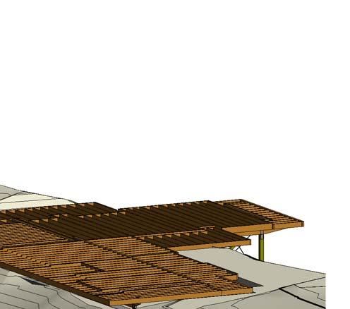
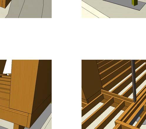
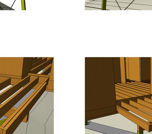
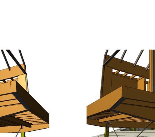
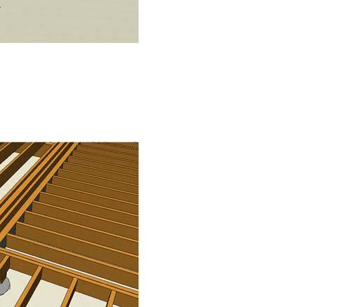
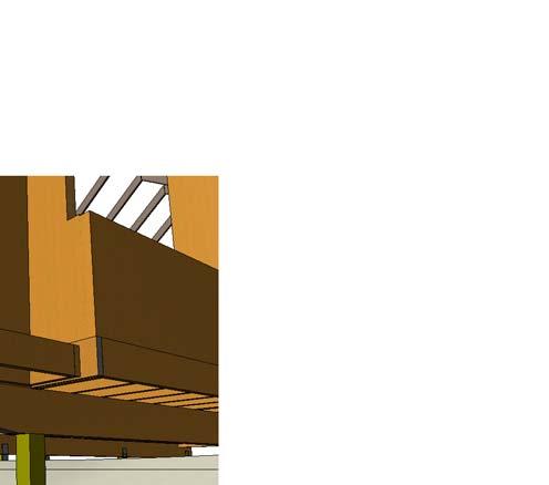
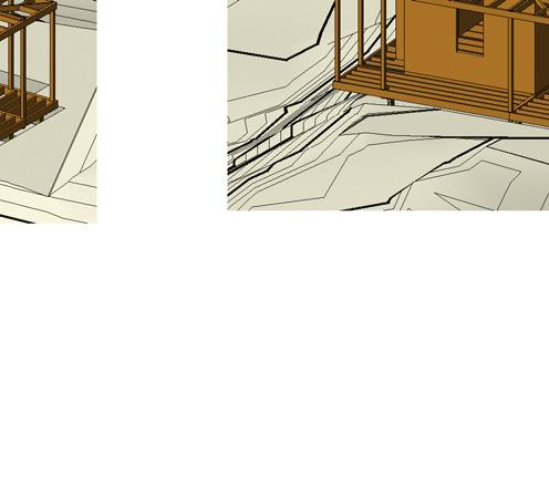
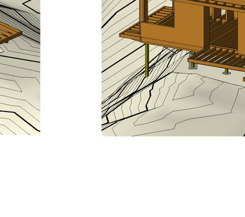
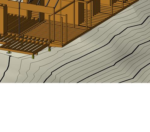
5 ISOMETRIC OUNDATIONS AND SITE ISOMETRIC LOOR STRUCTURE ISOMETRIC LOOR STRUCTURE ISOMETRIC LOOR STRUCTURE.0. No. Date By INAL REVIEW Description Chk App ISOMETRIC LOOR STRUCTURE ISOMETRIC LOOR STRUCTURE 0/08/0 :0:09 p.m. LOOR RAMING VIEWS Drawn J0000 S. Design


6 ROO RAMING DESIGN SITE WIND ZONE IS "EXTREME WIND" IN ACCORDANCE WITH NZS0. A B C D E VERIY ALL SETOUT DIMENSIONS WITH ARCHITECTURAL DRAWINGS. REER ANY DISCREPANCIES TO THE ENGINEER AND ARCHITECT IMMEDIATELY OR RESOLUTION AND CLARIICATION. ALL RAMING IXINGS TO BE IN ACCORDANCE WITH NZS0 OR "EXTREME HIGH WIND" CASE. CONTRACTOR MUST COMPLY WITH ALL NZS0 IXING AND DETAILING PROVISIONS. LAT ROO RAMING RIDGE BEAM -0x HYSPAN LAMINATE TOGETHER TO COMPLY WITH MANUACTURES DETAILS. 0x HYSPAN CONTINUOUS STEEL END RAME 0x HYSPAN CONTINUOUS SKYLIGHT -90x 0x HYSPAN CONTINUOUS SKYLIGHT 0x HYSPAN CONTINUOUS EX 90/0x SG8 PLATE AGAINST GLULAM. TOP O PLATE AT UNDERSIDE O PLY ROOING OR DIRECT IX. -M COACH SCREWS AT 00c.c DOUBLE S USE EX 90x OR EX0x WITH TIMBER CUT TO PROILE SO THAT S HARD TO UNDERSIDE O PLY ROOING AND IXED HARD TO WALL TOP PLATE. DOUBLE S TO EXTEND TO ACE O GLULAM. SKYLIGHT 0x HYSPAN CONTINUOUS P P EX 90/0 x TIMBER. TRIM TO ALLS. BACK SPAN 00mm WITH TIMBER PLATE AGAINST GLULAM. mm STAINLESS ROD OR IXING DETAILS REER TO ARCH DETAILS. SUGGEST mm STAINLESS PLATE AT GRID 0 / WITH -STAINLESS TEK SCREWS. AT OUTTER COLUMNS SANDWICH TIMBER TOGETHER BY REBATING. SUGGEST THREADED END AND LOCK NUT EACH SIDE O POST. 0x HYSPAN CONTINUOUS TO AR SIDE O SKYLIGHT. DOUBLE S DOUBLE S DOUBLE S DOUBLE S DOUBLE S SKYLIGHT P P 0x HYSPAN CONTINUOUS 0x90 ROSEWOOD BEAM UNDER RHS CRANKED S 0x0 RHS. MITER CUT AND SBW AT RIDGE WELDED END PLATES AND BOLTED CONNECTION TO GLULAM BEAMS. BEAMS TO BE TIMBER CLAD. 0x90 GL8 GLULAM BEAM EXTERNAL 0x90 GL8 GLULAM BEAMS EX 90/0x SG8 PLATE AGAINST GLULAM. TOP O PLATE AT UNDERSIDE O PLY ROOING OR DIRECT IX. -M COACH SCREWS AT 00c.c RHS CRANKED S 0x0X RHS MITER CUT AND SBW AT RIDGE WELDED END PLATES AND BOLTED CONNECTION TO GLULAM BEAMS. ALL LAT ROO CONSTRUCT WITH 0X SG8 S IN HORIZONTAL PLANE U.N.O. BUILD UP TO SUIT ALLS (REER TO ARCH DETAILS). ENSURE BUILT UP RAMING IS IXED TO TOP O S WITH NAILING SIZE AND SPACING AT LEAST EQUIVALENT TO PLYWOOD TO RAMING IXINGS. PROVIDE 0x STRINGER TO ACE O WALLS ON GRID,, A, D. PROVIDE EX90x/0X SB8 STRINGER TO grid E AND, TRIM TO SUIT HEIGHT O PLYWOOD AND ALLS. PITCHED ROO RAMING (GRID A-D) ALL ROO RAMING IN ACCORDANCE WITH NZS0 WITH 0x SG8 S AT 00c.c CEILING mm PLY LINING TO BE INSTALLED AS CEILING DIAPHRAGM. COLUMNS : 90x90 GL8 GLULAM COLUMNS P: 00x0x RHS COLUMNS.0. INAL REVIEW STEEL END RAME 0x0 RHS MITRE CUT & WELDED S AS PER MAIN DETAILS. MITRE CUT & SITE WELDED TO 00x0 RHS COLUMNS. 0x SHS WINDOW HEADER WITH x0 PLATE TO WELDED EACH SIDE BEWTEEN COLUMNS. mm THREADED ROD HANGAR AT MIDSPAN RIDGE TO WINDOW HEADER. - 0x HYSPAN DOUBLE HYSPAN AS SHORT CANTILEVERS. SOLID STUD RAMING UNDER. CPC80 x TO 0X90 GLULAM BEAM, AND CPC80 ROM ACE O STUD TO UNDERSIDE O HYSPAN AT EDGE O WINDOW OPENING. D E ROO RAMING PLAN : 0 0/08/0 :0:0 p.m. ROO RAMING Drawn Design : 0 J0000 S.


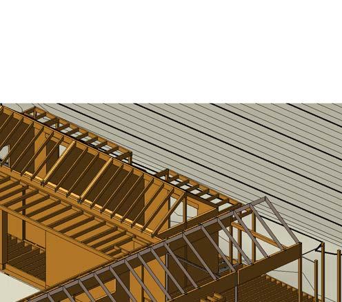

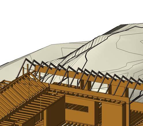
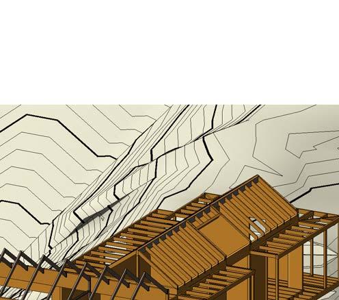


7 ROO VIEW Roof View.0. No. Date By INAL REVIEW Description Chk App Roof View Roof View 0/08/0 :0: p.m. D RAMING VIEWS Drawn J0000 S. Design
8 ROO STRINGER TO WALL PROVIDE 90x NOG ON EDGE, TO ALIGN WITH ROO STRINGER. BOLT STRINGER TO WALL NOGS WITH M COACH SCREWS AT 00c.c PERIMETER 0x HYSPAN TO BE SEATED MIN mm ONTO STUD WALL. JOIST TO BEARER OR CONDITIONS WITH JOISTS TO EACH SIDE O BEARER, PROVIDE JHx0 HANGARS. -xgxmm HEX HEAD SS SCREWS AND -NAILS PER LANGE. 0mm PACKER ON JOIST TO SUPPORT WALL. 90x90 SG8 BEARER ALL 90x90 BEARER CONNECTIONS TO PILES TO PROVIDE kn TENSION OR COMPRESSION ALONG THE BEARER AND TIMBER JOISTS SUITABLE OR ANCHOR PILE CONNECTION SPECIICATION. LUMBERLOK kn PILE IXING DETAIL INTENDED. MINIMUM 000mm EMBEDMENT BELOW INISHED GROUND LEVEL. JOISTS S. INTERNAL PILES MINIMUM 00mm EMBEDMENT BELOW INISHED GROUND LEVEL. S. RIDGE BEAM CONNECTION O S TO RIDGE BEAM TO BE IN ACCORDANCE WITH NZS0. TO WALL CONNECTION IN ACCORDANCE WITH nzs0 DETAILING. -90x SG8 LINTELS TO NZS0 PROVIDE NOGS B/W RATRES AND IXING PLATE TO U/S O S OR INSTALLTION O WINDOWS. JOISTS CONNECTION TO TOP O BEARERS TO BE IN ACCORDANCE WITH NZS0. PROVIDE SOLID BLOCKING ON EDGE O LOOR STRUCTURE. ALL PILES ARE CONSIDERED ANCHOR PILES SO ADJACENT JOISTS REQUIRE kn IXINGS AS REQURIED BY NZS0. Level 000 GLULAM BEARER CANTILEVER BEAM -90x SG8, WITH kn STRAP TO DOUBLE STUDS UNDER, AND 00x00 NAIL PLATE TO END STUDS. PROVIDE kn TIE DOWN TO LOOR STRUCTURE WALL BEAM 00x HYSPAN WALL BEAM SPAN ULL LENGTH O GRID WALL OPENING - PART O WALL PRENAIL. PROVIDE -.x90 NAILS INTO END O CANTILEVER BEAM AND MULTIGRIPS. HYSPAN BEAM PROVIDE kn HOLD DOWN TO HYSPAN BEAM AT EDGES O OPENINGS GREATER THAN 900mm PROVIDE BOUNDARY JOIST OVER BEARER ALONG THIS EDGE. TRIPPLE JOISTS PROVIDE SINGLE JOIST HANGER TO MIDDEL JOIST THEN PAIR O BOWMAK B ANGLE BRACKETS TO OUTTER JOISTS. MINIMUM 000mm EMBEDMENT BELOW INISHED GROUND LEVEL. S JOIST DOUBLE STUD DOUBLE STUD TRIPPLE JOIST S INTERNAL PILES MINIMUM 00mm EMBEDMENT BELOW INISHED GROUND LEVEL. S 90x90 GL8 POST WALL ROO INTERACE WALL RAMING TO EXTEND TO TOP O S. PLY BRACING TO EXTEND TO TOP O WALL. PROVIDE ADDITIONAL NOGS IN WALL RAMING AS NECSSARY OR INISHING WALL AND CEILING LININGS ax SG8 LINTEL S. Level 00 PROVIDE NOG BETWEEN JOISTS AT NOTCH OR 0MM SETDOWN. Level 000 S. Section A : 0 S. Section B : 0 S. S. HYSPAN LINTEL HYSPAN BEAM Level 0-90x SG8 LINTEL TO NZS0 JOISTS NOTCH 0mm OR DECK SETDOWN. S. 90x90 GL8 POST WALL BEYOND DECK JOIST AND STRUCTURE S..0. INAL REVIEW JOISTS 8 S. DECK BEARER PROP 90x90 H STRUT NOTCH INTO BEARER S. Section C : 0 MINIMUM 000mm EMBEDMENT BELOW INISHED GROUND LEVEL. INTERNAL PILES MINIMUM 00mm EMBEDMENT BELOW INISHED GROUND LEVEL. 0/08/0 :0: p.m. SECTIONS SHEET Drawn Design : 0 J0000
9 E MITRE CUT AND.S.B.W JOINTS S 0x0x RHS STEEL RAMES BETWEN GLULAM BEAMS S. 8 S. / TIMBER PLATE 0mm O BACK O POST. EXTEND TIMBER HARD TO BACK O RETURN ASCIA. 0x0x RHS 0x0x RHS mm THREADED ROD HANGER. WELD NUT TO UNDERSIDE O RHS. PROVIDE LOOSE LOCKING NUT TO SECURE ROD. ROD TO EXTEND THROUGH BOX SECTION AT WINDOW HEAD LEVEL BELOW AND SECURE WITH DOUBLE LOCK NUT. MITRE CUT AND.S.B.W JOINTS 0x GL8 BEAM S. 0 PILE AND CROSS BRACE 0mm STAINLESS STEEL ROD BRACE. AT BOTTOM O COLUMN, DRILL ROD CENTRALLY THROUGH PILE AND PROVIDE PL WASHER AND NUT TO BACK SIDE. CHECK IN WASHER OR LEVEL BEARING. STEEL END WALL RAME x GL8 BEARER BOWMAC B08 BRACKET OR BEARER ON OPPOSITE ACE TO CONNECT TO X GLULAM. S. S. 90X00 SG8 BEARER DECK JOISTS S. 90x90 GL8 POST PROVIDE 0mm SOLID TIMBER PACKER. ALLOW 0mm DEPTH O ASCIA TO CONTINUE BELOW PACKER. BOLT COLUMN TO WITH M BOLTS. PROVIDE PAIR O MULITGRIPS OR IXING O 0xHYSPAN TO BACK O. Level 000 0x SHS WITH x0pl ACING. 00x0x RHS POSTS 00x0x RHS POSTS x GL8 x GL8 x GL8 x0 PLATE TO OVERLAP COLUMN EACH SIDE AND BE SITE WELDED mm.w TO COLUMN ACE. 0X SHS TO SITE WELD TOP AND BOTTOM TO RHS. POST. COLUMN BASE OUTTER LANGE O SHS TO EXTEND TO TOP O BEARER BELOW. PROVIDE -M COACH SCREWS x 0 LONG INTO END O BEAM. PROVIDE PL 90 SQ BASE PLATE TO COLUMN AT TOP O GLULAM BEAM WITH -# STAINLESS SCREWS x INTO TOP O GLULAM. GLULAM BEAM SET DOWN 0mm BELOW MAIN LOOR JOISTS. S. MINIMUM 000mm EMBEDMENT BELOW INISHED GROUND LEVEL. S. Section D : 0 S. Section J : 0 ** IXING O P COLUMNS AT GRID 0 PL END PLATE.W.A.R TO COLUMN PROVIDE -Mx0 COACH SCREWS DOWN INTO TOP O GLULAM BEARER SPACE AT mm ROM ACE O COLUMN, CENTRELINE O BEARER. A B C D E D E S. S. S. GLULAM BEAMS S. -90x SG8 LINTEL TO NZS0-90x SG8 LINTEL TO NZS0-90x SG8 LINTEL TO NZS0 0x90 ROSEWOOD BEAM LINTEL TO NZS0 OOTING BEAM OOTING TO MATCH GROUND CONTOUR, WITH TOP O OOTING AT OR JUST BELOW INISHED GROUND LEVEL. S..0. INAL REVIEW DECK S UNDER IN WALLS DECK BEARER GLULAM BEARER GLULAM BEARER MINIMUM 000mm EMBEDMENT BELOW INISHED GROUND LEVEL. S. Section : 0 S. Section I : 0 0/08/0 :0: p.m. SECTIONS SHEET Drawn Design : 0 J0000
10 JOIST CONNECTION SS CT0 CLEATS EACH SIDE ( TOTAL PER JOIST) TO JOIST EACH SIDE O PILE. NAILS INTO BEARER AND JOIST PER BRACKET) NOTCH TIMBER PILE TO BE LUSH WITH TOP O SS PLATE. BEARERS/PILE BRACKET xmm STAINLESS STEEL H BRACKET. -M TO PILE AND -M TO BEARER. BOLTS TO BEARER AT 0MM ACROSS AND 80mm VERT. BOLTS TO PILE AT 0mm ACROSS X 80MM VERT. BEARER DECKING HYSPAN BEAM -M THROUGH BOLTS STAINLESS STEEL PROVIDE PLATE WASHERS S. STRIP OOTING TYPICAL TAPER PILE TO SUIT TAPER PLATES. 0 PILE STRUT MAY BE BELOW GROUND, CAST INTO PILE. 90x90 H STRUT NOTCH BEARER AS SHOWN PROVIDE 00x00 NAIL ON PLATE EACH SIDE TO BEARER. ULLY NAIL. STRUT TO PILE CAREULLY NOTCH ACE O PILE 0mm DEPTH. INSTALL M THROUGH BOLT WITH PLATE WASHER. 90x90 GL8 POSTS NOTCH OR mm SEATING O TIMBER BEAM BEARER CONNECTION GRID : 0 STRUT TO DECK BEARER : 0 TYPICAL VERANDAH POST TO HYSPAN : INTERNAL LOOR JOISTS DECK STRUCTURE 90x90 GL8 POSTS PRECISION REBATE OR BASE IXING PLATES MAIN BEARER CONNECTION TO PILES TO THE REQUIREMENTS O "ANCHOR PILE" NZS0. USE LUMBERLOCK kn ANCHOR PILE IXING DETAILS. M M BEARER CONNECT WITH BOWMAC B08, RE-DRILL OR mm BOLTS TO SUPPORTING BEARER. STRIP OOTING AND PILE NOTCH JOIST DO NOT OVERCUT NOTCH VERTICALLY OR HORIZONTALLY OR JOIST WILL BE REJECTED BY THE ENGINEER. MAIN LOOR JOISTS SPLIT SUPRESSION INSTALL -mm LONG g SCREWS AS SHOWN ON JOIST CENTRELINE. 0 EXTERNAL INTERNAL ABRICATED BRACKETS MATCH BOWMAC BRACKET DETAIL B9 BUT DO NOT SPLIT BOTTOM O PLATE DRILL OR -M BOLTS OR IXING TO TRIPPLE/DOUBLE SUPPORT JOISTS. PLATE WASHERS TO JOISTS. BOUNDARY JOIST MIN X.dia X 00 NAILS BUTT NAILED TO ENDS O EACH JOIST PROVIDE PAIRS O MULIGRIPS ROM BOUNDARY JOIST TO ENDS O SUPPORT JOISTS (NOT SHOWN OR CLARITY) DOUBLE/TRIPPLE DECK JOISTS 0 00 Callout of Section C : 0 JOIST NOTCH STRENGTHENING : 0 8 VERANDAH POST TO DECK : HYSPAN RIDGE BEAM -M THROUGH BOLTS TO SIDE STUDS -M THRU BOLT TO STUDS IN WALL AT 900c.c HYSPAN RIDGE BEAM.0. INAL REVIEW x.0mm STRAP BRACE OVER TOP O BEAM TO WALL PLATE. ULLY NAIL) x.0mm STRAP BRACE OVER TOP O BEAM TO WALL PLATE. ULLY NAIL) TOP PLATE 0 TOP PLATE STUDS BELOW RIDGE BEAM. RIDGE BEAM TO WALL GRID A, B, C : M M M M PAIR CPC80 EACH SIDE O, EACH SIDE O RIDGE BEAM. ABRICATED STEEL BRACKET. GEOMETRY AS PER BOWMAC B9 - WITHOUT RAG SPLIT END. BOLTS OR RIDGE BEAM TO HAVE 0mm END DISTANCE TO RIDGE BEAM, AND BOLTS TO COLUMN TO BE CENTRAL. ALL M BOLTS WITH PLATE WASHERS. 90x90 GLULAM POST REBATE OR STEEL PLATE. RIDGE BEAM SUPPORT GRID D : 0 0/08/0 :0: p.m. As indicated DETAILS SHEET J0000 Drawn S. Design
11 GLULAM DECK BEAM ACE O BEAM mm PAST END O BEARER. ROUTER OUT BEAM TO ALLOW BEARER TO SOCKET INTO ACE O BEAM. BOWMAC B8 BRACKET, USE BOLTS TO BEAM, AND COACH SCREWS TO BEARER. JOIST AS STINGER. BOLTED BACK TO MAIN BEAM AT 00c.c WITH M BOLTS TO ARCH DETAILS. GLULAM BEARER x TAPER CUT BEARER AS SHOWN. REER TO ARCHITECTS DETAILS. TAPER TO INISH LUSH WITH UNDERSIDE O GLULAB BEAM. M COACH SCREW WITH PLATE WASHER. 00mm LONG, PREDRILL INTO END O BEARER GLULAM LOOR BEAM BEAM NOTCHED OVER BEARER.. PROVIDE B8 BRACKET TO INTERNAL SIDE, LOCATE TO INSIDE EDGE O BEARER TO ALLOW OR BOUNDARY JOIST. PROVIDE CPC80 TO BOTTOM O GLULAM BEAM IXED INTO BEARER. BOLTS mm EDGE DISTANCE TO PLATE, AND 0mm EDGE DISTANCE TO JOIST. NOTCH BEARER AND MAKE PLATE LUSH WITH TOP O BEARER. ABRICATEDSTAINLESS PLATE mm STAINLESS PLATE,.W.A.R JOINS SANDWICH BETWEEN S -M STAINLESS BOLTS TO JOISTS, WITH PLATE WASHERS. MM SEATING PLATEx 90 WIDE WITH - Mx COACH SCREWS TO BEARER MM VERTICAL ACE PLATE x 90 WIDE, - Mx00 STAINLESS COACH SCREWS TO BEARER. END PLATE 90mm WIDE. BOLTS 0mm SIDE AND BOTTOM EDGE DISTANCE, 0MM TOP EDGE DISTANCE. ROD BRACE CL BEARER CL CL JOIST STEEL RAME BASE PLATE AND COACH BOLTS AS NOTED PREVIOUSLY ON GRID RAME. 0mm TIMBER PLATE TO TOP O GRID BEARER TO PACK TO LOOR LEVEL. 0 LOOR JOISTNAIL LAMINATED TO ACE O BEARER. GLULAM BEARER GRID NOTCH BOTTOM O UPPER BEARER OVER LOWER BEARER. PROVIDE PAIR O CPC80 AS SHOWN PLUS SKEW NAILS.x00. BEARER TO PILE BRACKET ABRIACTED STAINLESS STEEL H BRACKET WITH 8 - M THROUGH BOLTS AS SPECIIED OR PILE AT GRID E/ 90x90 SG8 BEARER LUSH WITH TOP O DECK JOISTS. CPC80 EACH SIDE DOWN TO TOP O BEARER. PROVIDE Kn TIE TO DOUBLE JOIST AND PAIR O CPC80 ROM CONNECTION TO GLULAM BEARER UNDER. DOUBLE DECK JOISTS ON GRID E LUSH WITH TOP O DECK JOISTS. CPC80 EACH SIDE DOWN TO TOP O BEARER. NOTE: OR SINGLE JOISTS, JUST USE JOIST HAGNERS OR CONNECTION TO 90x90 BEARER. DOUBLE STUDS mm PLY BRACING EACH SIDE. PROVIDE kn TIE DOWN ROM STUDS TO JOISTS. USE STRAP BRACE, SLOTTED THROUGH LOORING. STRAP BRACES S GRID E/ PAIR O CPC80 BRACKETS ROM JOISTS TO BEARER AND SINGLE CPC80 ROM ACE O BEARER TO U/S DOUBLE JOISTS. BEARER TO PILE STANDARD STAINLESS H BRACKET WITH M TO BEARER AND PILE. AS DETAILED IN GRID E/ DETAIL. BEARER TO PILE BRACKET mm PLATE 'H" BRACKET..W.A.R x0 VERTICAL PLATES X SEATING PLATE ON TOP O TIMBER PILE. NOTCH INTO TIMBER PILE AS NECESSARY. -M BOLTS TO PILE AND BEARER. 0mm STAINLESS STEEL ROD BRACE PROVIDE 0x0PL CENTRALLY SLOTTED 0 WIDE x 00mm OR ROD,.W.A.R ROD TO PLATE. x0mm STAINLESS BOLT TO ABRACITED BEARER PLATE. ROD TO BE DRILLED THROUGH BASE O TIMBER PILE, WITH 0x0x PLATE WASHER AND NUT AS NOTED ON LOOR RAMING PLAN. GRID /E SECTION : 0 CONNECTION OVER BEARERS : 0 GRID E/ CONNECTION DETAILS : 0 RHS S. PROVIDE HOLE IN LANGE ACE TO ALLOW OR INSTALLATION O COACH SCREW. 0x0x RHS S. 0x0x RHS PROVIDE PL TAG PLATE WELDED TO EDGE O RHS LANGE. -Mx0 COACH BOLT CENTRAL INTO TOP O GLULAM. GLULAM BEAM INTERNAL 0mm STAINLESS STEEL ROD ULLY THREADED WITH NYLOC NUTS ACTORY EPOXY 0mm INTO OVERSIIZED AND GROOVED HOLES. MANUACTURE TO SUPPLY EPOXY AND CONSTRUCTION SPECIICATION OR ENGINEERS APPROVAL x0x RHS RAME PROVIDE PL TAG PLATE WELDED TO EDGE O RHS LANGE. -Mx0 COACH BOLT CENTRAL INTO TOP O GLULAM. GLULAM BEAM INTERNAL 0mm STAINLESS STEEL ROD ULLY THREADED WITH NYLOC NUTS ACTORY EPOXY 0mm INTO OVERSIIZED AND GROOVED HOLES. MANUACTURE TO SUPPLY EPOXY AND CONSTRUCTION SPECIICATION OR ENGINEERS APPROVAL GLULAM BEAM EXTERNAL 0mm STAINLESS STEEL ROD ULLY THREADED WITH NYLOC NUTS BOTH SIDES O POST. ACTORY EPOXY 00mm INTO OVERSIZED AND GROOVED HOLES. MANUACTURE TO SUPPLY EPOXY AND CONSTRUCTION SPECIICATION OR ENGINEERS APPROVAL. GLULAM BEAM EXTERNAL COACHSCREW IXINGS AT c.c TOP AND BOTTOM IXING M M MIDDEL IXINGS. IXING MUST HAVE EMBEDMENT LENTH INTO GLULAB BEAM O 0mm MINIMUM. PROVIDE HOLE IN RHS LANGE OR ACCESS TO INSTALL COACH SCREW ROSE WOOD BEAM. REER TO OTHER DETAIL SECTION OR IXING AND CONNECTION DETAIL..0. INAL REVIEW 0 BOX, x0pl SIDES mm SEAL WELD ULL LENGTH O MEMBER AND SHS/PLATE INTERACES.W.A.R SITE 0PLATES TO ACE O SHS POST 0 BOX, x0pl SIDES mm SEAL WELD ULL LENGTH O MEMBER AND SHS/PLATE INTERACES.W.A.R SITE 0PLATES TO ACE O SHS POST GLULAM COLUMN GL8 90x90 TO MATCH BEAM. PROVIDE -.dia x 00 SS NAILS AT c.c (BETWEEN COACH SCREWS). GLULAM TO STEEL RAME GRID 8 GLULAM TO RAME GRID : 0 : 0 : 0 GLULAM BEAM AT GRID 0/08/0 :0: p.m. DETAILS SHEET Drawn Design : 0 J0000 S.


12 E 0x0x RHS S.W.A.R TO SUPPORT BRACKET. PROVIDE HOLE IN BOTTOM LANGE OR ACCESS TO TIGHTEN IXING BOLT. 90x90 GL8 POSTS PRECISION REBATE OR BASE IXING PLATES. REER TO VERANDAH POST TO DECK DETAIL OR STANDARD IXINGS. BOUNDARY JOIST CONNECTION AS SHOWN IN STANDARD VERANDAH POST TO BASE DETAIL. 90x90 SG8 PACKER BETWEEN BOUNDARY AND OLLOWING JOIST. CONNECT TO INNER JOIST WITH PAIR O MULITGRIPS. PROVIDE 00w X h NAILON PLATE EACH SIDE. ULLY NAIL. ABRIACTED BRACKET OR PILE CONNECTION REER TO BUILDING SECTION A 88 CPC80 BRACKET RHS IXING ABRICATED STEEL PLATES 80mm WIDE 0mm END PLATE TO RHS MM TOP AND BACK ACE PLATE..S.B.W JOINTS..W.A.R TO RHS. BRACKET TO BE ROUTERED INTO GLULAM BEAM OR TIGHT IT JOINT. M0x COACH SCREW TO TOP M COACH BOLT THROUGH ACE. PLYWOOD ROOING TIMBER PLATE EXTEND TO VERANDAH. BOLT TO GLULAM -M COACH SCREWS AT 00c.c WITH 80mm PENETRATION TO GLULAM WITH JOIST HANGER TO PLATE. STAINLESS STEEL BRACKET DIMENSIONAL DATA AS PER B08 BOWMAC BRACKET, BUT NO SEATING PLATE TO BASE. DRILL OR xm COACH BOLTS TO POST, AND -M OR BEAM. 90x90 GL8 POST 0 0 0x90 BEAM RHS ROO S GLULAM BEAM ABRICATED BRACKET SEE DETAIL BESIDE. PL 80x80 CAP, 80xPL VERTICAL TAG PLATE...W.A.R. M0x0 COACHBOLT WELDED TO TOP CENTRAL TO CAP PLATE. INSTALL IN PREDRILLED HOLE kn LATERAL TIE. USE STRAP WRAPPED AROUND COLUMN, ULLY NAILED. (SIMILAR OTHER END) PLYWOOD BRACING ULLY NAILED TO PERIMETER RAMING AND TO BOTH TOP PLATES IN ACCORDANCE WITH BRACING SPECIICATION DOUBLE STUDS SANDWICH BRACKET PLATE BETWEEN AND BOLT THROUGH WITH - M BOLTS mm PLATE mm PLATE S. DOUBLE TOP PLATE DOUBLE STUDS PLYWOOD ROOING NAIL TO THE SPECIICATIONS O E WALL BRACING. DOUBLE ROW O NAILS ONTO DOUBLE LOCATIONS AT BRACE WALLS. -EX 0/90x PAIR CPC80 TO GLULAM SINGLE CPC80 TO HYSPAN ASCIA BEAM xkn TIE DOWN STRAP TO STUDS PAIR O 0T TYLOK TO TOP PLATES -EX 0/90x PAIR CPC80 TO GLULAM SINGLE CPC80 TO HYSPAN ASCIA BEAM xkn TIE DOWN STRAP TO STUDS PAIR O 0T TYLOK TO TOP PLATES GRID BEARER TAPER. : 0 ROO DETAIL GRID /E : 0 SUPPORT OR GLULAM GRID E/ Glulam stud support : 0 TYPICAL OR DOUBLE STUD SUPPORTS INTERNALLY TO 0x90 GLULAM AT IN WALLS..0. INAL REVIEW LUMBERLOCK kn ANCHOR PILE N.T.S 0/08/0 :0: p.m. DETAILS SHEET Drawn Design : 0 Approver J0000 S.
Timber to Timber - Timber to Concrete - Timber to Steel
 01/2017 TIMBER CONNECTORS NOT TO BE USED IN EXTERIOR SITUATIONS Stainless Steel alternatives are available where stated Timber to Timber - Timber to Concrete - Timber to Steel MiTek manufactures and markets
STRUCTURAL BRACKETS CATALOGUE
 0/2 STRUCTURAL BRACKETS CATALOGUE SUPERIOR QUALITY, HOT DIP GALVANISED, HEAVY DUTY BRACKETS FOR FIXING TIMBER TO TIMBER, TIMBER TO CONCRETE, TIMBER TO STEEL The BOWMAC product range is designed to cut
SECTION R507 DECKS DECKING LEDGER BOARD BEAM. FOOTING BEAM SPAN CANTILEVER For SI: 1 inch = 25.4 mm FIGURE R507.2 DECK CONSTRUCTION
 SECTION R507 DECKS R507.1 Application. The provisions of this section shall provide prescriptive requirements for the design and construction of all uncovered, wood-framed, single-span exterior decks.
STRUCTURAL BRACKETS CATALOGUE
 08/2011 STRUCTURAL BRACKETS CATALOGUE SUPERIOR QUALITY, HOT DIP GALVANISED, HEAVY DUTY BRACKETS FOR FIXING TIMBER TO TIMBER, TIMBER TO CONCRETE, TIMBER TO STEEL The BOWMAC product range is designed to
How-To-build guide carport
 How-To-build guide carport What you can build using this guide This guide will show you how to build a free-standing, open-sided single carport. Before you begin building Contact your local territorial
LVL8 H1.2 GENERAL FRAMING. Eco Friendly Revolutionary H1.2 Treatment Azotek by Zelam
 LVL8 H1.2 GENERAL FRAMING Eco Friendly Revolutionary H1.2 Treatment Azotek by Zelam NPIL/MARCH2015 Introduction to NelsonPine LVL8 H1.2 NelsonPine LVL is an engineered wood composite made from rotary peeled
DUTCH GABLE FREESTANDING CARPORT
 DUTCH GABLE FREESTANDING CARPORT STRATCO OUTBACK ASSEMBLY INSTRUCTIONS. Your complete guide to building a FREESTANDING Outback DUTCH GABLE CARPORT BEFORE YOU START Carefully read these instructions. If
TRADITIONAL GABLE ATTACHED PATIO AND CARPORT. Your complete guide to building an ATTACHED Outback TRADITIONAL GABLE PATIO or CARPORT
 TRADITIONAL GABLE ATTACHED PATIO AND CARPORT STRATCO OUTBACK ASSEMBLY INSTRUCTIONS. Your complete guide to building an ATTACHED Outback TRADITIONAL GABLE PATIO or CARPORT BEFORE YOU START Carefully read
A. Rough carpentry includes but is not limited to the following:
 SECTION 06100 ROUGH CARPENTRY PART 1 - GENERAL 1.01 RELATED DOCUMENTS A. Drawings and general provisions of Contract, including General and Supplementary Conditions and Division-1 Specification Sections,
Strong, lightweight composite structural I -Beam.
 Strong, lightweight composite structural I -Beam. This Installation Guide has been prepared as a source of information to provide general guidance to consultants and in no way replaces the services of
GLOSSARY OF TERMS SECTION 8
 GLOSSARY OF TERMS SECTION 8 Anchor Bolt Angle Base Plate Bay Blocking CCB Centerline Chord Cladding Clip Closure Strip An A-307 steel bolt embedded in the concrete footing to anchor the base plate of the
CLEARSPAN GABLE STRATCO OUTBACK ASSEMBLY INSTRUCTIONS. WITH GAZEBO END ATTACHED PATIO
 CLEARSPAN GABLE WITH GAZEBO END ATTACHED PATIO STRATCO OUTBACK ASSEMBLY INSTRUCTIONS. Your supplementary guide to building an ATTACHED CLEARSPAN GABLE VERANDAH or PATIO WITH GAZEBO END This set of instructions
CURVED ROOF ASSEMBLY INSTRUCTIONS ATTACHED VERANDAH. Your supplementary guide to building an ATTACHED CURVED ROOF VERANDAH or PATIO BEFORE YOU START
 ROOF ATTACHED VERANDAH ASSEMBLY INSTRUCTIONS Your supplementary guide to building an ATTACHED ROOF VERANDAH or PATIO This set of instructions should be used in conjunction with the Stratco instruction
SECTION ROUGH CARPENTRY 1.1 DESCRIPTION OF WORK:
 SECTION 061000 - ROUGH CARPENTRY 1.1 DESCRIPTION OF WORK: A. Definition: Rough carpentry includes carpent~y work not specified as part of other sections and which is generally not exposed, except as otherwise
Pryda Timber Connectors
 Pryda Timber Connectors Pryda Lintel Guide Engineered Steel Wall Lintels March 2014 ESSENTIAL NOTES PRYDA PRODUCT GUIDES INTRODUCTION The information in this Product Guide is provided for use in Australia
3.1 General Provisions
 WOOD FRAME CONSTRUCTION MANUAL 107 3.1 General Provisions 3.1.1 Prescriptive Requirements The provisions of this Chapter establish a specific set of resistance requirements for buildings meeting the scope
Acceptable Standards of Domestic Construction
 Truss or Rafter Roof Batten Triple grip fastener (for roof trusses) Foil lined Insulation blanket Top plate Sprocket Brick tie Top plate strapping at 1200mm max. cts. Note: Holding down straps should be
Glulam Connection Details
 T E C H N I C A L N O T E Glulam Connection Details Note: This version is superseded by a more current edition. Check the current edition for updated design and application recommendations. ENGINEERED
DECKS. Stairway illumination Positive attachment of ledger Lateral load connection required board (R507.2) required (R ) (R311.7.
 required (R ) (R311.7.") DECKS Max. riser height-7 ¾ Min. tread depth-10 Landings required at (R311.7.5.1) (R311.7.5.2) top and bottom of stairs (R311.7.6) Notched guardrail post NOT allowed Graspable handrail required Spacing
DECKS Max. riser height-7 ¾ Min. tread depth-10 Landings required at (R311.7.5.1) (R311.7.5.2) top and bottom of stairs (R311.7.6) Notched guardrail post NOT allowed Graspable handrail required Spacing
F I X I N G B R O C H U R E
 F I X I N G B R O C H U R E Joist Hangers Joist Hangers on Steel Beams Fixing Masonry Hangers Speedy Joist Hangers Lateral Restraint Straps Roof Tie Down Straps Herring Bone Joist Strut Bat 'U' Nail Plate
hy JOIST futurebuild structural lvl design & Installation Guide: 2.1 december 2013
 futurebuild structural lvl hy JOIST design & Installation Guide: 2.1 december 2013 Information contained within this manual is specific to the hyjoist range of LVL products and cannot be used with any
hyjoist Options Range Installation Guide
 hyjoist Options Range Installation Guide For on-site, technical and product support, including assistance in sizing freecall 1800 808 131 hyjoist Guide for Installation hyjoist is a cost effective, lightweight
Corner Potting Store Assembly Instructions
 Corner Potting Store Assembly Instructions English SS225E Before assembly We recommend that time is taken to read the instructions before starting assembly, then follow the easy step by step guide. The
Gable HomeshedsTM INSTALLATION BEFORE YOU START TOOLS REQUIRED GUIDE LARGE SPAN. Council Approval. Before Starting
 INSTALLATION GUIDE Gable HomeshedsTM LARGE SPAN BEFORE YOU START Council Approval It is important to contact your local council before building your Stratco Gable Homeshed. You will have already received
RAIL PANEL AT TRANSITION SECTION PLAN - POST DETAIL PLAN - TUBE SPLICE. Colorado Department of Transportation. Staff Bridge Branch
 Limits of pay length for Bridge RailType 10M (For post spacing, see Dwg. No. B ) B60610 (Use with B60610A) 8 min. 1 max. 8 min. 1 max. 10 0 Max. 10 0 Max. post spacing 10 0 Max. 2 5 Post 1 x 1 slotted
Dura-Lock Roof System
 DLR-14 Dura-Lock Roof System Assembly and Installation Instructions Read the instructions before starting the job. They explain the steps required to produce a finished product that will meet factory specifications.
Sturdi-Wall Design Manual for SW46, SW66, SW63, SW64, SW60, SW83, SW84, and SW80 Models
 Sturdi-Wall Design Manual for SW46, SW66, SW63, SW64, SW60, SW83, SW84, and SW80 Models Project Number ME086-05 by Brent Leatherman, P.E. Timber Tech Engineering, Inc E-Mail: bl@timbertecheng.com January
Posi-Joist Installation Guide. A guide for storage, handling and installation of the MiTek Posi-Joist floor system
 Posi-Joist Installation Guide A guide for storage, handling and installation of the MiTek Posi-Joist floor system Posi-Joist Installation Details A B C D F E A Masonry Wall Connection Details Blockwork
Renaissance Pavilion. Assembly Manual
 Renaissance Pavilion Assembly Manual Thank you for your purchase of this pavilion. Renaissance Pavilion Assembly Manual This manual is designed to simplify the assembly process, however we recommend having
24" max from each end of the ledger. See detail 6A & 6B, typ. both ends IRC R Ledger R507.2
 NOTE: All exposed lumber to be pressure treated (P.T.) or decay resistant. Fasteners for P.T. wood shall be hot-dipped galv. or stainless steel, typical. see pages 2 & 5 for footings 8'-0" -10'-0" Beam
MULTISPAN GABLE WITH HIP END ATTACHED PATIO
 MULTISPAN GABLE WITH HIP END ATTACHED PATIO STRATCO OUTBACK ASSEMBLY INSTRUCTIONS. Your supplementary guide to building an ATTACHED MULTISPAN GABLE VERANDAH or PATIO WITH HIP END This set of instructions
DEEP-DECK PANEL INSTALLATION DETAILS BERRIDGE MANUFACTURING COMPANY
 DEEP-DECK PANEL INSTALLATION DETAILS 800-669-0009 www.berridge.com INDEX INDEX INSTALLATION INSTRUCTIONS INSTALLATION INSTRUCTIONS INSTALLATION INSTRUCTIONS INSTALLATION INSTRUCTIONS INTRODUCTION TO TYPICAL
SECTION STRUCTURAL STEEL FRAMING PART 1 - GENERAL 1.1 RELATED DOCUMENTS
 SECTION 05 12 00 - STRUCTURAL STEEL FRAMING PART 1 - GENERAL 1.1 RELATED DOCUMENTS A. Drawings and general provisions of the Contract, including General and Supplementary Conditions and Division 01 Specification
SHED PACK Step 1: Choose your shed type.
 SHED PACK Step 1: Choose your shed type. Industrial Shed Open FarmShed Shed Pack / Types of Sheds Drawing # S0104.A001 Hanger Shed =DISCLAIMER= Please read and agree to Purlin Brackets Terms and Conditions
Heartland Perma-Column 1841 E 1450 Rd. Lawrence, KS (785)
") 141 E 1450 Rd. Lawrence, KS 66044 (75) 594-5696 Perma-Column Installation Instructions i Unlike any other concrete post-frame foundation system, Perma-Column Precast Concrete Piers use 10,000 psi concrete
141 E 1450 Rd. Lawrence, KS 66044 (75) 594-5696 Perma-Column Installation Instructions i Unlike any other concrete post-frame foundation system, Perma-Column Precast Concrete Piers use 10,000 psi concrete
T-BRACE / I-BRACE DETAIL WITH 2X BRACE ONLY
 August 10, 2010 T-BRACE / I-BRACE DETAIL WITH 2X BRACE ONLY ST - T-BRACE 2 R MiTek Industries, Chesterfield, MO Page 1 of 1 Note: T-Bracing / I-Bracing to be used when continuous lateral bracing is impractical.
ATLANTIS RAIL Contact Information
 ATLANTIS RAIL Contact Information Customer Service (800) 541-6829 (508) 732-9191 Spectrum System Installation Instructions Atlantis Rail s Spectrum System is an easy to install, universal cable railing
Index Pipe Hangers and Straps
 Index Pipe Hangers and Straps Fig. 1 Standard Clevis Hanger MSS-SP-69, Type 1 WW-H-171E, Type 1 Page 14 Fig. 1CI Clevis Hanger for A.W.W.A. Page 16 Fig. 81 Clevis Hanger WW-H-171E, Type 12 Page 70 Fig.
Typical Deck Details Based on the City of Nixa Residential Deck Ordinance
 Typical Deck Details Based on the City of Nixa Residential Deck Ordinance The use of this package in lieu of submitted drawings applies to Single Span, Single Level, Residential Decks ONLY. Decks must
A Shell construction
 A Shell construction A 4/2012 Content 1 BASE AND WALL ANCHORING 1.1 Base with mortar bed 1.2 Base with sill plate 1.3 Base with raised sill plate 1.4 Concrete base (mortar bed) 1.5 Concrete base (sill
How-To-build guide Garden shed
 How-To-build guide Garden shed What you can build using this guide This guide will show you how to build a re-locatable garden shed. Before you begin building Contact your local territorial authority to
STEEL PIPE GUIDERAIL 01/01/
 NOTES PIPE RAILING & POSTS: Pipe Rails and s shall be in accordance with ASTM A5 Grade B for standard weight pipe and ASTM A500 Grade B, C or D or ASTM A50 for structural tube. Bars for handrail supports
C.00. Ullrich Aluminium Co. Ltd. Ulltraclad Aluminium Cladding September Wall Batten Elevation. Horizontal battens between verticals at soffit
 Horizontal battens between verticals at soffit 2 C.04 600 600 600 600 Cavity batten at 600 mm centres 1 C.03 Batten fixing points 1 C.04 1 C.07 1 C.12 1 C.13 1 C.14 Meter Box Window 1 C.08 1 C.09 800 800
FASTENERS BUILDING DEPARTMENT
 FASTENERS BUILDING DEPARTMENT 952-446-1660 WWW.CITYOFMINNETRISTA.COM This handout is intended only as a guide and is based in part on the 2015 Minnesota Residential Code, Minnetrista City ordinances, and
Site Installation Guide
 Site Installation Guide Site Checklist Stop and read this now. Tick box when checked. Floor Joist Layout If a floor joist design/layout was done, was a site copy of the layout provided with the joists,
WHY YOU SHOULD USE TUFFLOOR. components
 Tuffloor DESIGN GUIDE WHY YOU SHOULD USE TUFFLOOR Strong and Easily Installed Tuffloor is a steel floor framing system designed for strength and ease of installation, and is an easy and economical alternative
Typical Deck Details
 Botetourt County guard decking ledger board fasteners existing house floor construction guard post attachment ledger board attachment to existing house s footing beam -to-beam connection post-to-beam connection
Stratco Sanctuary INSTALLATION BEFORE YOU START TOOLS REQUIRED GUIDE
 INSTALLATION GUIDE Stratco Sanctuary Verandahs, Patios and Carports BEFORE YOU START It is important to check with your Local Government Authority prior to the installation of your new Stratco Sanctuary
INDEX PAGE RELEASE SECTION NUMBER DATE
 INSTALLATION INSTRUCTIONS For Wind Zone 1 (other Wind Zones available on request) Version 11/20/2002 INDEX PAGE RELEASE SECTION NUMBER DATE Approval INTRODUCTION 2 2/26/2001 GENERAL INSTALLATION 3 2/26/2001
Installation Procedures
 Installation Procedures Nutec Bigsix Roofing sheets properly laid and fixed in accordance with recommendations will provide many years of trouble-free protection from the elements. Failure to follow these
AUXILIARY FRAMING AND ACCESSORIES
 CUSTOM CABINETS & RACKS STRUT AND ACCESSO- RIES JUNCTION KITS ANGLE AND BRACE KITS SPLICE KITS BRACE KITS INSTALLATION KITS WALL ANGLE KITS RUBBER END CAPS SUPPORT INSTALLATION AND SUPPORT KITS STANCHION
SHED PACK. Sheds are commonly constructed using portal frames.
 SHED PACK Sheds are commonly constructed using portal frames. This pack relates to purchasing portal frame purlin bracket sets. Ruest our free generic engineered and certified shed plans. SHED PACK Step
INSTALLATION GUIDE. Outback. Flat Attached BEFORE YOU START ADDITIONAL MATERIALS TOOLS REQUIRED. VERAnDAHS PATIOS CARPORTS
 INSTALLATION GUIDE Outback VERAnDAHS PATIOS CARPORTS Flat Attached BEFORE YOU START It is important to check your Local Government Authority requirements before the installation of your new Stratco Outback
Ulltraclad Aluminium Cladding. Contents. 1.0 General Information Design Information Installation Information 7. 4.
 Ulltraclad Aluminium Cladding Contents 1.0 General Information 2 2.0 Design Information 4 3.0 Installation Information 7 4.0 Maintenance 10 5.0 Health & Safety 10 1 1.0 General Information 1.1 Introduction
SECTION ROUGH CARPENTRY
 SECTION 06100 PART I - GENERAL 1.01 DESCRIPTION A. Scope: Work of this Section shall include all materials and installation necessary to provide Rough Carpentry as shown and detailed on the Drawings and
INSTALLATION GUIDE. Outback Clearspan Gable BEFORE YOU START ADDITIONAL MATERIALS ADDITIONAL MATERIALS WITH COOLDEK ROOFING
 INSTALLATION GUIDE Outback Clearspan Gable WITH COOLDEK ROOFING BEFORE YOU START It is important to check your Local Government Authority requirements before the installation of your new Stratco Outback
VERSA-LAM. An Introduction to VERSA-LAM Products
 44 VERSA-LAM An Introduction to VERSA-LAM Products VERSA-LAM is one of the strongest and stiffest engineered wood products approved in the UK. 241 302 356 406 VERSA-LAM products are excellent as floor
OUTBACK FLAT ATTACHED VERANDAH PATIO CARPORT - INSTALLATION GUIDE BEFORE YOU START TOOLS REQUIRED ADDITIONAL MATERIALS
 BEFORE YOU START It is important to check your Local Government Authority requirements before the installation of your new Stratco Outback Flat Verandah. It is the builder s responsibility to ensure any
(50 FT FT) MICHIGAN DEPARTMENT OF TRANSPORTATION 10-0" 7-6" 8-0" 6-0" Truss Depth. 3" sheets 5 & 6 of 10) DEPARTMENT DIRECTOR. Kirk T.
 MICHIGAN DEPARTMENT OF TRANSPORTATION 10-0 7-6 8-0 6-0 Truss Depth. 3 sheets 5 & 6 of 10) DEPARTMENT DIRECTOR. Kirk T.") Column truss connection (See details sheets 3 & 4 of 10) \ Span (Odd number of panels) \ Span (Even number of panels) Back truss chord Top truss chord \ Truss Chord splice Truss depth (See details \ Left
Column truss connection (See details sheets 3 & 4 of 10) \ Span (Odd number of panels) \ Span (Even number of panels) Back truss chord Top truss chord \ Truss Chord splice Truss depth (See details \ Left
APPLICATION FOR A BUILDING PERMIT
 APPLICATION FOR A BUILDING PERMIT City of San Jacinto 595 S. San Jacinto Ave San Jacinto CA 92583 95.487.7330 fax 95.654.9896 Must print legibly, submit (3) sets of building and plot plans. Fill out all
Products for fixing to Steelwork and Decking
 Products 8.0 Beam Clamp - Single Support 8.1 Universal Joint for any variable Angle Adjustment 8.2 Beam Clamp TCS for Header Rails 8.3 Beam Clip for Cross Support/ Dimensioning of Bolts 8.4 Beam Clip for
TYPE J (20 FT - 40 FT) MICHIGAN DEPARTMENT OF TRANSPORTATION 10-0" 7-6" NOTE: sheet 5 & 6 of 10) DEPARTMENT DIRECTOR. Kirk T.
 MICHIGAN DEPARTMENT OF TRANSPORTATION 10-0 7-6 NOTE: sheet 5 & 6 of 10) DEPARTMENT DIRECTOR. Kirk T.") Column truss connection Chord splice (see details (See details sheets 3 & 4 of 10) s Top truss chord Free end panel 10-0" Support end panels length varies (See chart below) \ Truss Back truss chord Top
Column truss connection Chord splice (see details (See details sheets 3 & 4 of 10) s Top truss chord Free end panel 10-0" Support end panels length varies (See chart below) \ Truss Back truss chord Top
SECTION ROUGH CARPENTRY
 SECTION 06100 ROUGH CARPENTRY PART 1 GENERAL 1.1 DESCRIPTION OF WORK A. The work includes furnishing all labor, materials and equipment required to complete the Rough Carpentry work as shown on the Drawings
ROOF-CEILING CONSTRUCTION
 CHAPTER 8 ROOF-CEILING CONSTRUCTION SECTION R801 GENERAL R801.1 Application. The provisions of this chapter shall control the design and construction of the roof-ceiling system for all buildings. R801.2
Structural Calculations
 Structural Calculations Project Project Number 14 266 Napier Girls High School Performing Arts Building (Arthur Building) Document Control Date Version Extent of Revision Status 21 September 2015 A Original
S-DECK PANEL INSTALLATION DETAILS BERRIDGE MANUFACTURING COMPANY
 S-DECK PANEL INSTALLATION DETAILS MANUACTURING 800-669-0009 www.berridge.com INDEX INDEX INSTALLATION INSTRUCTION INSTALLATION INSTRUCTION INSTALLATION INSTRUCTION INSTALLATION INSTRUCTION INTRODUCTION
ALUMINUM PIPE GUIDERAIL 01/01/
 NOTES PIPE RAILING & POSTS: Structural Tube, Pipe and Bar shall be in accordance with ASTM B22 or ASTM B429, Alloy 606-T6. End Rail 90 bends and corner bends with maximum 4-0" post spacing, may be Alloy
Butt Two pieces of wood meeting with flat sides adjoining usually at right angles. Some type of connector is needed to prevent movement.
 Wood Connections There are basically five different types of connectors: Interlocking (carpentry joints), Dowel, Metal Connectors, Special Formed Connectors and Adhesives. I Interlocking (Carpentry Joints)
Potting Store Assembly Instructions
 Before assembly We recommend that time is taken to read the instructions before starting assembly, then follow the easy step by step guide. The instruction sheet is only a guide to the assembly. Certain
GABLE ROOF CARPORT RECOMMENDED INSTRUCTION MANUAL
 GABLE ROOF CARPORT RECOMMENDED INSTRUCTION MANUAL Table of Contents Introduction 2 Components 3 Step 1a Marking out the Perimeter of the Carport with Footing only 3 Step 2a Footing Set-Out for Concrete
INSTALLATION SHOP DRAWINGS FOR MINNEAPOLIS, MN
 MINNEAPOLIS, MN 2-0- 2-- General Notes Abbreviations Deviations from Architectural Specifications Deviations from Architectural Drawings ALUM. = ALUMINUM B.O. = BY OTHERS CONT. = CONTINUOUS. = CLEARANCE
DIY SHED GUIDE Planning your Project I Simple Illustrations I Hints
 Easy Step by Step Guide DIY SHED GUIDE Planning your Project I Simple Illustrations I Hints TIMBERLINK. MADE OF TASMANIA. DIY Shed Guide Timberlink Green Outdoor Structural Range Timberlink Green Outdoor
Table of Contents. e-joist Design Information Page 2. Floor Joists Supporting Floor and Ceiling Loads Only 3. e-joist Construction Information 4
 Table of Contents e-joist Design Information Page 2 Floor Joists Supporting Floor and Ceiling Loads Only 3 e-joist Construction Information 4 e-joist Installation Details 5 Bearing at Supports 5 Support
Verge Flashing. Verge Flashing. Only use if flashings requirements can be site measured before ordering. Verge Clip
 Tolerance Detail (recommended) Verge Closure Verge Channel Verge Clip Verge Flashing VERGE CHANNEL RIVETTED TO EUROSEAM AT APPROX 400MM CENTRES USING 4.8 X 12MM RIVETS. NB: DO NOT RIVET AT HALTER POSITION
Midwest Roadside Safety Facility
 2 Spaces @ 75" [05]= 150" 3810 4 Spaces @ 3 Spaces @ 4 Spaces @ 18.75" 37.5" [953]= 37.5" [953]= [476] 112 1/2" 150" = 75" 2857 3810 [05] 18 476 7 Spaces @ 75" [05]=525" [13335] 21 20 18 17 1615 14 1312
Fibre Cement G C. Batten Fixing Setout ST-01. Jan 2014 A4 PROFILE DATE SCALE DETAIL DETAIL NO. Plank joint. 600mm stud crs.
 Plank joint 600mm stud crs 600mm 600mm 600mm Horizontal Structural Timber Cavity atten 50x20mm H3.1 atten fixing points 800mm 800mm 300mm 800mm Max. Nog spacing 50mm All intermediate battens to be 50x20mm
TREX PERGOLA INSTALLATION INSTRUCTIONS
 RECOMMENDED TOOLS/SUPPLIES: Pencil 4' Level Measuring Tape Framing Square/Speed Square 8' High Step Ladder (Two recommended) Hacksaw or Bolt Cutters Socket Wrench with 9/16" Socket and 3/4" Deep Socket
Connection Philosophy. p NDS Chapter-by-chapter description Changes from previous editions Examples. Part 1: Member Design Webinar.
 Outline ASD and LRFD with the 2005 NDS Part 2 Connection Design Presented by: John Buddy Showalter, P.E. Vice President, Technology Transfer Connection philosophy p NDS Chapter-by-chapter description Changes
INS A KSR INSTALLATION INSTRUCTIONS STANDARD PROCEDURE. 1. Verify Curb Installation Required Installation Tools...
 INS-88.300-0A KSR INSTALLATION INSTRUCTIONS STANDARD PROCEDURE 1. Verify Curb Installation... 2 2. Required Installation Tools... 2 3. Unpacking the KSR... 3 4. Attach KSR Bottom Rail to Curb... 5 5. Attach
Joshua Woodsman
 CONSTRUCTION GUIDE of one of our design Please Note This electronic document is protected by the identifier against unauthorized dissemination on the Internet. Before building any structure make sure you
Deck Design Guide. One and Two Family Residential Dwellings
 Deck Design Guide One and Two Family Residential Dwellings The City of Lake Oswego is providing this information to help you design your deck, obtain a building permit and pass inspections. The standards
3. Are component and cladding design pressures consistent with ASCE 7 for the wind speed and exposure category (ASCE 7 Fig. 6-3)?
?") Mobile County Public Works Residential Plan Reviewers Checklist For Structural Requirements of Wood Framed Residences Recommendation: Permit as Noted Revise Plans and Resubmit MCPW Ref. No. Design Criteria:
Mobile County Public Works Residential Plan Reviewers Checklist For Structural Requirements of Wood Framed Residences Recommendation: Permit as Noted Revise Plans and Resubmit MCPW Ref. No. Design Criteria:
Deck Designer Specification Kit For. TimberTech. All rights reserved copyright 2015 AZEK Building Products
 Deck Designer Specification Kit For TimberTech All rights reserved copyright 2015 AZEK Building Products Deck layout diagram Top view without planks Bottom view with planks Top view with planks Page 2
CORRIGENDA TO STEEL CONNECTIONS SERIES 1 AND 2 Version 2
 ASI Head Oice Level 3, 99 Mount Street North Sydney NSW 060 Tel: 0 993 6666 Email: enquiries@steel.org.au (ABN)/ACN (94) 000973 839 www.steel.org.au Author: T J HOGAN Date: February 0 Page o 9 CORRIGENDA
 JOIST DETAILS Plate nail, 16d (0.15" x 1 ") at 1 on-center Blocking panel: 1 1 8" TJ Rim Board, 1 1 TimberStrand SL or TJI joist Toe nail, 10d (0.11" x ") at on-center A1 CS BEAM DETAILS L1 eb stiffener
Midwest Roadside Safety Facility
 19'-11 1/2" 6083 239'-11 1/2" 73139 Impact 1100C 25 43 5/16" 1100 upstream from the upstream face of the first shear fender downstream of the joint between barrier nos. 7 and 8 Upstream End Downstream
DIVISION 6 WOOD AND PLASTICS
 DIVISION 6 WOOD AND PLASTICS PART 1 - GENERAL 1.01 SUMMARY A. This Section includes the following: 1. Wood framing. 2. Wood supports. 3. Wood blocking. 4. Wood cants. 5. Wood nailers. 6. Wood furring.
INSTALLATION INSTRUCTIONS FOR PLASCORE F5075 FRAME WALL
 INSTALLATION INSTRUCTIONS FOR PLASCORE F5075 FRAME WALL The following information is provided by Plascore, Inc., as a general guideline for the installation of the F5075 Frame Wall System. This information
Office Installation Guidelines
 UH Structures Inc. dba Ebtech Industrial 2241 Industrial Drive Connellsville, PA 15425-6181 Telephone: 724-628-6100 Fax: 1-412-774-2429 www.ebtechindustrial.com Office Installation Guidelines INTRODUCTION
SIG-032-B TRAFFIC SIGNAL MAST ARM POLE AND MAST ARM DETAILS - CATEGORY III LUMINAIRE ARM (SEE CONTRACT) 6'-0", 8'-0", 10'-0" NOMINAL SPREAD
 6'-0, 8'-0, 10'-0 NOMINAL SPREAD") Michigan Department of Transportation 6'-0", 8'-0", 10'-0" NOMINAL SPREAD (SEE CONTRACT) LUMINAIRE ARM (SEE CONTRACT) POLE CAP 1'-6" (6'-0" ARM) 1'-10" (8'-0" ARM) 2'-0" (10'-0" ARM) NOMINAL RISE 2.38"
Michigan Department of Transportation 6'-0", 8'-0", 10'-0" NOMINAL SPREAD (SEE CONTRACT) LUMINAIRE ARM (SEE CONTRACT) POLE CAP 1'-6" (6'-0" ARM) 1'-10" (8'-0" ARM) 2'-0" (10'-0" ARM) NOMINAL RISE 2.38"
Clopay Models 835/837 Sliding Door System Installation Guide
 Clopay Models 835/837 Sliding Door System Installation Guide The aim of this instruction is to guide you through the process of construction and fitting of Sliding Doors. Due to the number of sizes available
NORMAL WEIGHT CONCRETE TOTAL-LEWIS-DECK GYPSUM BOARD 2 OR 3-PLY COMPOSITE TOTALJOIST TOP CHORD CONNECTION
 GENERAL DETAILS 100 TYPICAL FLOOR CONSTRUCTION NORMAL WEIGHT CONCRETE WELDED WIRE MESH FIBERGLASS BATT INSULATION (OPTIONAL) 18 GAUGE TIE WIRE 7/8" RESILIENT CHANNEL NOTE: CEILING MAY ALSO BE SUSPENDED
Attach Trusses and Rafters Faster
 Attach Trusses and Rafters Faster SDWC TRUSS Screw Truss-to-Plate Connections For Truss-to-Plate Connections The Strong-Drive SDWC TRUSS screw provides a truss- and rafter-to-top-plate connection. The
Pocket Door Kit PD1 / PD2 Installation Instructions. Kit Contents.
 Pocket Door Kit PD1 / PD2 Installation Instructions Kit Contents. 1, Create Rough Opening In Stud Wall Construct rough opening ensuring all sides are square and level. Rough opening should be; Height =
Collins Engineers Palmetto Islands County Park Boardwalk Repairs 03/28/2014 SECTION ROUGH CARPENTRY
 PART 1 GENERAL 1.1 RELATED SECTIONS SECTION 061000 ROUGH CARPENTRY A. Drawings and general provisions of the Construction Contract, including General Conditions and Division 1 Specification Sections, apply
Chapter 7 - Porch Framing
 Chapter 7 - Porch Framing Contents Chapter 7 - Porch Framing... 7-1 Timing & Prerequisites... 7-2 Concrete Porches Caps (Contractor)... 7-3 Organize the Porch Framing Lumber... 7-3 Types of Porch Roofs...
Midwest Roadside Safety Facility
 C 1690" A 42926 75" 1905 150" 3810 G E F F 11 10 9 8 7 6 5 4 3 2 C D D 25 18 17 16 15 14 13 12 11 10 9 8 7 6 5 4 3 2 1 21.2 G E Impact 2270P 17 Spaces @ 75" [1905] Spacing = 106' 3" [32385] 1 1662 1/2"
5/16" Flange nut. Bolt Keeper Plate (8" Sq. SYS.) (3) 1/2" x 3" Hex head connector zinc plated bolt w/ washers and nut. Anchor 3" sq. 7 Ga.
 (3) 1/2 x 3 Hex head connector zinc plated bolt w/ washers and nut. Anchor 3 sq. 7 Ga.") 2 1/2" x 2 1/2" x 10 Ga. 6" 5" 4" Variable Slipbase (8" Sq. SYS.) 5/16 Corner Bolt W/ nut 5/16" Flange nut Stub Insert (8" Sq. SYS.) Bolt Keeper Plate (8" Sq. SYS.) (3) 1/2" x 3" Hex head connector zinc
2 1/2" x 2 1/2" x 10 Ga. 6" 5" 4" Variable Slipbase (8" Sq. SYS.) 5/16 Corner Bolt W/ nut 5/16" Flange nut Stub Insert (8" Sq. SYS.) Bolt Keeper Plate (8" Sq. SYS.) (3) 1/2" x 3" Hex head connector zinc
Safety Glasses Safety Gloves Ladders Measuring Tape Spirit Level String Line. Tin-Snips Rivet Gun Caulking Gun Silicone Socket Set
 BEFORE YOU START Carefully read these instructions and refer to them constantly during each stage of construction. If you do not have all the necessary tools or information, contact Stratco for advice.
Attachment of Residential Deck Ledger to Side of Metal Plate Connected Wood Truss Floor Ladder. Installation Instructions Revised 9/2/2016
 Attachment of Residential Deck Ledger to Side of Metal Plate Connected Wood Truss Floor Ladder Installation Instructions Revised 9/2/2016 SBCA has been the voice of the structural building components industry