Installation Guide Simplicity 6. v3.5 lu171117
|
|
|
- Gwen Davis
- 6 years ago
- Views:
Transcription


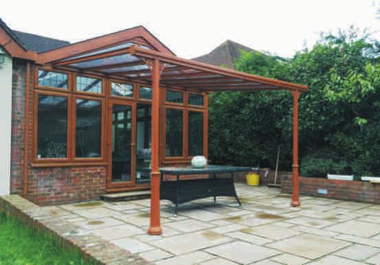


1 Installation Guide Simplicity 6 v3.5 lu171117


")


2 Tools Required Below is a list of tools that you will require to install the Simplicity 6 Canopy or Carport. Cordless Drill Mastic Gun Spirit Level Tape Measure 8mm Spanner 10mm Spanner 8mm Socket & Ratchet 10mm Socket & Ratchet 5mm & 6.5mm Drill Bit White Rubber Mallet Pozi Head Screwdriver & Flathead Hammer Roofing Square 36 Sash Cramp 45mm Hole Saw Aluminium Chop Saw Digging Equipment Parts Supplied Below is a list of the parts supplied with your new canopy. Please check that all parts are present before commencing the installation process. Gutter Extrusion Post Extrusion Roof Bar Extrusion End Roof Bars Wall Plate Gutter Trim Height 110mm Wall Plate End Plate Height 130mm Gutter End Plate Glass Sheets Glass End Enclosures 6mm x 16mm Pan Pozi Screw Bolt 5/8 Pozi Self Tapping Screws Type AB M6 Nylock Nut No. 12x 1 ¼ No. 10x 25mm Hexagon Self Hexagon Drill Drill Screws Screws Glazing Bar End Plate M6 X 20MM Hex Headed Bolts Gallow Support Bar Spigot Bolt Down Post Foot Above Ground (if required) In Ground Post Foot (if required) 2No. Joining Plate 18mm x 300mm x 2mm Joining Plate 61.5mm x 300mm x 2mm Joining Plate 70mm x 300mm x 2mm Please reference the CAD during installation as this is just a general guide, your CAD will provide you with more specific details for your install. 2
3 Preliminary Stages and Planning Before starting your install please check all components for quantity and damage. Below is a roof span chart which you MUST refer to in order to establish the maximum centre to centre dimensions of your roof bars and posts. SPAN Chart Roof Bars Up to 3.1m Projection POST SPACINGS Up to & Including 3.1m Projection System 6 600mm Roof Bar Spacings System 6 3m Post Spacings PLEASE NOTE A MAXIMUM OF 500MM OVERHANG ON THE GUTTER IS ALLOWED 500mm Max Overhang on the Guttering from Post 500mm Max Overhang on the Guttering from Post Before starting your installation please check all components for damage and ensure the parts are provided in the correct quantity. PLEASE NOTE, IF USING SELF CLEANING GLASS A MINIMUM PITCH OF 10 IS REQUIRED. At 3.2 metres projection the maximum pitch of your roof system is 13 due to glass length, contact the office for further details. Be aware! You must ensure all glass is installed with the film facing upwards (sky). This will ensure that if installing self cleaning glass it is the correct way up. Please note when ordering Pilkington Self Cleaning Glass: Pilkington Activ needs both daylight and rain to work effectively. When the roof angle gets too low the rain does not wash the loosened dirt off as effectively. A good flow of water across the glass is beneficial. Pilkington Activ still gives better results than ordinary glass with low angle roof applications. We recommend a minimum angle of 10 degrees. You are now ready to start installing the structure, following all steps within this guide. Lighting (if required) The lighting consists of an aluminium extrusion that can fit to either the bottom of the wall plate, or the back of the eaves beam. When installing lighting please consider cable exist and cable entry to the light channel. The lighting also comes with an electrical capacitor for each 6m of light and an optional external grade plastic box to house the capacitors if the installation requires that they be mounted outside.


4 STEP 1 Foundation Hole Positions for Posts Establish the height of the canopy/carport at the back (wall edge) and the height of the canopy at the front. The height at the front must be above 2.1m to meet the minimum legal head height requirement. Once you have established your height at the front and back, deduct the height at the front from the height at the back to give you The Fall (x). Measure distance 'x' up the wall and position your roof bar at this height on the wall. Let the other end touch the ground and where that touches will be the centre of your hole for the foundation. IMPORTANT: Use roofing square to ensure the bar used is held square to the wall. STEP 2 Digging of Holes You can either cast foundations first or dig holes for casting after. (Bolt to or cast in) Holes or foundations must be a minimum of 300x300x600 deep. This is only a guide. Please consult a structural engineer for verification 4
.")


5 STEP 3 Fitting of Wall Plate to the Wall Measure 25mm in from one end of the Wall plate and approx 55mm down from the top of the inside profile and mark before you drill. Drill the wall plate using the correct sized drill bit for the suitable wall fixings that you intend to use (not supplied). Once this is done repeat at the other end. Continue to drill holes in the wall plate at approx 55mm down and at approx 300mm centres. This is only a guide. Please consult a structural engineer for verification. See diagram You must ensure the wall plate is not twisted or bowed. Use a spirit level to make sure the wall plate is fitted level. Using suitable wall fixings, fix the wall plate to the wall, we recommend plastic caps are fitted over the screw/bolt heads for aesthetic reasons. STEP 4 Fitting of Post Feet to Posts Centralise the post foot to the post and attach using 2 x No. 12 x 1 ¼ self drill screws (Note the post foot is only suitable for surface mounting the posts. If your posts need to be concreted into the ground please follow step 4a overleaf) STEP 4a Fitting of Post Feet to Posts Centralise the post anchor to the post and attach using 2 x No12 x 1 ¼ self drill screws 5


6 STEP 5 Cutting the Posts Measure the height of the canopy/carport at the front and add to this dimension the depth of post that will be going into the ground. The total of this is the length at which your posts needs to be cut. STEP 6 Fitting of Post to Gutter Section Position the gutter section over the posts and ensure they are in the correct position and are spaced in accordance with the span chart. Ensure the post is square to the gutter section using a roofing square. Using 2 x No. 12 x 1 ¼ drill screws, secure through the front profile of the gutter into the post. Repeat on the inner side so that 4 screws in total are used to secure the post. STEP 7 If your canopy or carport is longer than 6m, you may need to join the gutter sections as follows: Joining Gutter Sections You will need the following to join every gutter beam: 4No. flat aluminium joining plates: 2No. 18mm x 300mm x 2mm, 1No. 70mm x 300mm x 2mm, 1No. 61.5mm x 300mm x 2mm 1No tube of Sudaflex marine grade sealer 1No roll of masking tape 4No. M6 x 20mm hex headed bolts 4No. M6 self locking nuts 1No. 6.5mm drill bit 1No mastic gun 1No drill with 8mm self driller attachment Industrial wipes Roll of industrial tissue paper 1. Make sure you only use Sudaflex; normal silicon sealer will not do. 2. Now apply a liberal amount of Sudaflex to both sides of the eave beam on the internal vertical sections and the underside of the gutter where the plate fits into this will enable you to bond the four joining plates. 6


7 3. Flatten any excess Sudaflex with the spatula and apply a generous amount of sealer around every edge of both plates. Then insert all plates half way in to one half of the join. 4. Apply ample amounts of Sudaflex across all corresponding areas of the opposite eaves beam 5. You are now ready to marry the two eaves beams together but you must ensure they are flat and level to each other. 6. Once you have married the two beams together you must leave at least a 3mm gap between the two but no greater than 5mm 6a. Drill 2 No. x 6.5mm holes through the top 18mm joining plate and gutter channel and either side of the join line at the back of the Gutter Channel. Using the 6mm Hex Headed Bolts and Nuts supplied bolt through the gutter channel and joining plates and tighten up. 7. After around 15 to 20 minutes and once the sealer has had time to harden stand the Eaves Beam with legs attached up, and attach the bars as described in the above procedure. 8. Once your canopy is glazed, your legs are plumb and your eaves beam is level up and down, left and right, and front to back, ensure your gutter is dry and the surface temperature at least 4 degrees. If you are installing in the winter, you may need to use a heat gun. 9. Then you will need to apply the final amount of Sudaflex into the bottom of the Eaves Beam, please see diagrams below: 3mm gap between the two but no greater than 5mm 7


8 10. Apply a generous amount around the edges of the flat plates inside the gutter and ensure all gaps are filled with Sudaflex internally. 11. Fit the external gutter cover plates. 12. Fit the cover plate centrally over the gutter join line, these plates are fixed using Sikaflex. 13. Remove this section because the bolts are hidden by the trim. STEP 7a Fitting the Gallows Support Bar The gutter support bar is designed to span from post to post or from post to end cap underneath the gutter, fix the bar through the gutter channel using self drillers every 300mm both sides of the gutter as shown in the below diagram. STEP 8 Stand Post & Gutter Beam Up Using the excavated hole, position each of the posts into the centre of the hole and lean the whole frame forward so that the back of the posts leans against the front of the hole; please see diagram overleaf. If the posts are to be surface mounted, please secure the posts ensuring they are plum and square. STEP 9 Fitting of the Glazing Bars Pre-drill the glazing bar that is going to fit into the gutter section. 15mm in from the edge and 30mm from the end of the bar drill your 6.5mm hole. Do this on both sides of the bar. This will allow the glazing bar to overhang the gutter section. Please see the images below. 8


9 Starting with the End Glazing Bar, push this bar into the wall plate so that it is pushed back as far as possible and ensure the outside profile lines up with the edge of the wall plate. Rest the other end of the glazing bar on the radius inner section of the gutter section. Using a 6.5mm drill bit, drill 1 No. hole through the bottom radius profile of the wall plate ensuring this also goes through the flat section of the glazing bar. Locate a 6mm x 16mm pan pozi screw bolt through the hole and apply m6 nyloc nut. Using an 8mm ratchet and screw driver tighten up. Repeat this process on the other side of the glazing bar. Please see the image below: Make sure the glazing bar is in line with the gutter beam, then using the same fixing method as the wall plate secure the glazing bar to the gutter section. Your pre-drilled holes will determine where you drill through on the radius of the gutter section. Please see diagram below: Repeat the above with the last glazing bar at the other end of the wall plate and gutter beam to stabilise the wall plate and gutter beam while you seal the wall plate in the following section. DO NOT FIT ANY MORE GLAZING BARS AT THIS STAGE STEP 10 Sealing Wall Plate Against the Wall If flashing or silicone is required to seal the wall plate against the wall, it needs to be done prior to the glass sheets being fitted. STEP 11 Glass Sheets The glass sheet comes with a protective film fitted on the coated face. This needs to be removed prior to fitting. The side with the film needs to be fitted facing the sunlight. PLEASE NOTE IF USING SELF CLEANING GLASS A MINIMUM PITCH OF 10 IS REQUIRED. 9

10 STEP 12 Glazing the Canopy The glass will be supplied cut to the correct dimensions needed for the installation. You need to measure the width of glass and then work out your bar centres to ensure your last piece of glass fits correctly and is not too big or too small. DO NOT attempt to glaze the canopy until you have done this calculation. When you push the glazing bar into the wall plate the gasket will have a tendency to fold back. You need to flick the rubber gasket out so it lips over the glazing bar and glass. The glass into the glazing should be a nice, tight fit. You will need to apply a suitable lubricant to the top and bottom gasket prior to inserting the glass. (Not supplied) We suggest fairy liquid. Always fit the glass into the next glazing bar at floor level before you lift and position into the fixed bar on the frame. When you are fitting the glass sheet into the fixed glazing bar (with the next bar attached) it is recommended that you locate the top corner into position first with the other end about 200mm away from the finished position. When the glass is located in this position it is recommended that you use a Sach Cramp or rachet straps to ensure the glass stays within the glazing bar and does not spring out while you are pushing the glass into the bar. Then working from that top corner you steadily work along pushing the glass into the glazing bar which reduces the gap until the full length of glass is located into the glazing bar. See illustration below Secure the glazing bar in place as shown in STEP 9 STEP 13 Fitting of the F -Section Secure the glazing bar to the gutter section using M6 X 16MM Pan Pozi Bolts and M6 Nuts. Ensure the end of the glass is fitting flush with the edge of the glazing bars as shown overleaf. 10


11 Cut the f -section the same width as the distance between the inner edge of the two glazing bars. See the image below. STEP 13a Fitting of Bar End Plates Secure the bar end plate into the end of the glazing bar using a No. 10 x 25 hexagon headed screw (supplied). Please see the image below. 11
.")


12 STEP 13b Fixing the Gutter Trim There are 3 trims the same length as the gutter, if the gutter is over 6m and has a join then stagger the trim so that the join is in a different place. The trim fits into the channel on the front and the back of the gutter, 1 trim on the front and 2 trims on the back (inside of the gutter). Simply hold the trim close to the channel and using a rubber or fibre mallet tap the trim into place ensuring the bottom 2 trims have the flat section facing down. The top trim on the inside is fitted with the flat section of the trim facing upwards. STEP 14 Fitting of Gutter End Caps Ensure the gutter is completely dry, then apply a continuous bead of Sudaflex around the end of the gutter extrusion, then line up the 4 holes on the gutter end plate with the port holes on the end of the gutter section and using 4 No. x 5/8'' self tapping screws secure in place. Finally using a dobbing stick or finger with disposable gloves apply a bead around the internal gutter section at the end. Repeat at the other end. Please see diagrams below: STEP 15 Fitting of Wall Plate End Caps Line up the 2 No. holes on the wall plate end plate with the port holes on the end of the wall plate section and using 2 No. x 5/8'' self-tapping screws secure in place. Repeat at the other end. Please see diagram below: STEP 16 Make Sure Your Canopy/Carport is Square To ensure the carport is square, using the roofing square, attach one edge of the square to the wall plate and the other edge will need to continuously touch the other edge of the square. This will ensure the gutter beam is perpendicular to the wall plate. 12


13 STEP 16a Ensuring your Canopy/Carport is Level Using a spirit level ensure the front beam is completely level and your posts are plumb. STEP 17 Concrete around the Posts Using the correct aggregate apply to the excavated holes and make good. STEP 18 Victorian Upgrade Drainage System If you are not installing the Victorian Upgrade, please skip this step and move onto step 18a. Drill a hole no more than 40mm diameter in the gutter section where your post is to be located. Push the post in to the gutter section below the hole. Please see diagram below Victorian Upgrade Base Casting 40mm outlet hole above ground covered by Victorian Upgrade Post Foundation 600 Post Foot Dry Mix Concrete
14 Note: 1. You must ensure the bottom of the hole has at least 100mm of dry mix concrete under the post to prevent subsidence of the post, and that is compacted hard. 2. Ensure as you fill the 300 x 300 x 600 foundation, that you fill the centre of the post level to the bottom of the 40mm hole to prevent rainwater going into the bottom of the post. 3. We recommend that when installing above ground outlets, you perform this procedure on every post to minimise puddles. Disclaimer: We cannot be held liable for puddles of excess rainwater around the column base. STEP 19a Standard Drainage System Drill a hole 45mm diameter using a hole saw in the gutter section where your downpipe is to be located, Insert the outlet into the hole and tighten. Push the downpipe in to the gutter section below the hole over the outlet. Using the downpipe clips provided secure to one of the posts or the wall depending on the position of your outlet. STEP 19b Capping off the Fixings Using the supplied caps, ensure the fixings have been capped off and the structure has been cleaned. STEP 20 Applying the Stickers When applying the logo ensure to fix one at each end. STEP 21 Fitting the Gutter Support Channel If supplied, then the Gutter Support channel (see profile image) fits directly underneath the Gutter Channel. It is held in place by using No12 x 1 ¼ drill screws every 300mm directly through the flange on both the outside and inner face. STEP 21a Fitting the Gallows Brackets Once the Gutter Support Channel is fitted you can now fit the Gallows Brackets. Using 2 x No12 x 1 1/4 drill screws fix the Gallows brackets directly into the post and then into the support channel you have previously fitted. See photo below. Using caps provided cap off all screw heads. Please see images overleaf. 14

15 Image shows gutter channel fitted. Image shows gallows brackets fitted to gutter channel and post. Please see the position of the fixings. Please see the position of the fixings. STEP 22 Lighting installation (if required) Inside of the light channel you will find a 12 Volt LED self-adhesive strip light, to access this just unscrew the aluminium end cap and slide out the polycarbonate lenses. You will need to connect the black and red cables to some compatible flex cable that is small enough to run through the trims on the alfresco, or through the wall plate and the main bars. Attaching the light channel to the Simplicity 6 eaves beam: Before you attached the light channel please consider the cable route and ensure you have enough cable to run it through the main bar and out of the wall plate to the capacitor. Then you need to drill up through the trim channel above the light channel into the main bar next to the main bar fixing bolt, then crimp the cables that exit the light channel with the additional cable required for the run, if the hole in the light channel is not already drilled, slide the lens out of the light channel by unscrewing the aluminium end cap and drill the hole using a 6mm drill bit ensuring it is aligned to the main bar hole you have just drilled. Once you have passed the cables through the hole simply snap the light into place or using a rubber mallet tap it into the light channel as below image. Then run the cables up the main bar and out of the wall plate at the desired location. 15


16 Attaching the lighting to the Simplicity 6 wall plate: To do this drill a hole through the back of the light channel (facing the wall) in the desired location for cable exit using a 6mm drill bit, crimp the cables to the red and black LED cables exiting the light channel and feed the extended cables through the hole and run them into the building or the plastic external box supplied and connect them to the capacitor. Then slide the polycarbonate lens back into the light and screw the end cap back on to the light channel. The capacitor will then need to be powered to the mains either via a fused spur or a plug socket as per the specification detailed on the lighting capacitor. End. 16

17 v3.5 lu171117
Installation Guide Simplicity 16. V2.9 Lu171117
 0845 869 6006 www.canoports.co.uk Installation Guide Simplicity 16 V2.9 Lu171117 Tools Required Below is a list of tools that you will require to install the Simplicity 16 Canopy or Carport. Cordless Drill
Installation Guide Simplicity Alfresco. V1.9 Lu070318
 0333 305 5272 www.canoports.co.uk Installation Guide Simplicity Alfresco V1.9 Lu070318 Tools Required Below is a list of tools that you will require to install your the Simplicity Alfresco System. Cordless
Installation Guide Contemporary Alfresco V1.3 LU
 Installation Guide Contemporary Alfresco V1.3 LU 010818 Tools Required Below is a list of tools that you will require to install you're the Contemporary Alfresco System. Cordless Drill Mastic Gun Spirit
INSTALLATION INSTRUCTIONS
 Tools required for the installation. A. Core Drill 87mm Drill bit B. Tape measure C. Spirit Level D. Marking pen E. Caulking gun F. Cutting Pliers G. Cordless Drill and Philips head bit, 5mm Drill bit.
GROWING BETTER THROUGH DESIGN. 6ft Lean-To LEAN-TO. Assembly Instructions 04/02
 GROWING BETTER THROUGH DESIGN 6ft Lean-To LEAN-TO Assembly Instructions 04/02 6ft Lean-To Greenhouse Base Plan Introduction/Tools/Contents / / Contents This is a copy of our Lean-To greenhouse base plan.
Fitting Instructions
 Fitting Instructions = Actions. Red = Notes you must read before continuing. Grey = Only applies to canopies over 4m widths. Overview 1. Tools you will need. 2. What you will need to provide. 3. Description
INSTALLATION INSTRUCTIONS
 Tools required for the installation. A. Core Drill 87mm Drill bit B. Tape measure C. Spirit Level D. Marking pen E. Caulking gun F. Cutting Pliers G. Cordless Drill and Philips head bit, 5mm Drill bit.
Gardman Lean-to Greenhouse Assembly Instructions
 Page 1 Gardman Lean-to Greenhouse Assembly Instructions Our Help Line provides support and advice to customers of Summer Garden Buildings after ordering. For advice before you buy you can phone us free
This installation guide has been created to assist in constructing a Liniar conservatory roof from a kit format.
 1.00 - Introduction This installation guide has been created to assist in constructing a Liniar conservatory roof from a kit format. Please note, each roof has been individually designed to meet specific
Dura-Lock Roof System
 DLR-14 Dura-Lock Roof System Assembly and Installation Instructions Read the instructions before starting the job. They explain the steps required to produce a finished product that will meet factory specifications.
Installation Guidelines
 Page 1 Tools You ll Need 4 ft. Carpenter s level Chalk line (to mark U channel locations) Cordless drill/nut driver Caulking gun Chop saw with a metal cutting blade on it (required to make accurate and
YUKON PATIO COVER INSTALLATION INSTRUCTIONS
 YUKON PATIO COVER INSTALLATION INSTRUCTIONS Before You Begin: Consult your local building department for any required permits You may be required to obtain a building permit for this structure. Contact
Stratco Sanctuary INSTALLATION BEFORE YOU START TOOLS REQUIRED GUIDE
 INSTALLATION GUIDE Stratco Sanctuary Verandahs, Patios and Carports BEFORE YOU START It is important to check with your Local Government Authority prior to the installation of your new Stratco Sanctuary
INSTALLATION GUIDE. Outback. Flat Attached BEFORE YOU START ADDITIONAL MATERIALS TOOLS REQUIRED. VERAnDAHS PATIOS CARPORTS
 INSTALLATION GUIDE Outback VERAnDAHS PATIOS CARPORTS Flat Attached BEFORE YOU START It is important to check your Local Government Authority requirements before the installation of your new Stratco Outback
Document: Installation Overview Guide No: 017a Description: Omega Canopy, Lean-To Style, Post-Supported, Glass-Clear Plate Polycarbonate Roof Panels
 Page 1 of 11 Sections: Section No. Section Description Page No. 01 Essential Tools 2 02 Tools that will make Installation easier 2 03 Items to be supplied by Installer 2 04 main components 3 05 Overview
OUTBACK FLAT ATTACHED VERANDAH PATIO CARPORT - INSTALLATION GUIDE BEFORE YOU START TOOLS REQUIRED ADDITIONAL MATERIALS
 BEFORE YOU START It is important to check your Local Government Authority requirements before the installation of your new Stratco Outback Flat Verandah. It is the builder s responsibility to ensure any
Synseal assembly guide 2009:Synseal assembly guide /2/09 12:38 Page 1. Conservatory Roof Assembly Guide
 Synseal assembly guide 2009:Synseal assembly guide 2007 9/2/09 12:38 Page 1 Conservatory Roof Effective from February 2009 Synseal assembly guide 2009:Synseal assembly guide 2007 9/2/09 12:39 Page 6 3.1
Curium 19H Installation Instructions & Parts List
 Curium 19H Installation Instructions & Parts List Illustration Curium 19H Right Hand Page 1 of 15 01/07/2016 Revision 2.1 IMPORTANT This shower screen / enclosure must be installed by suitably qualified
Greenhouse Assembly Instructions
 Greenhouse Assembly Instructions Our Help Line provides support and advice to customers of Summer Garden Buildings after ordering. For advice before you buy you can phone us free 7 days a week on 0800
RTS518 - Rhino Heavy Duty 2 & 3 Crossbar System Hyundai iload, imax, i800, H-1.
 RTS518 - Rhino Heavy Duty 2 & 3 Crossbar System Hyundai iload, imax, i800, H-1. NOTE: Please read these instructions carefully prior to installation. Check the contents of kit before commencing fitment
Installation Instructions
 Installation Instructions Alcove Enclosure Before Installation please check that your shower enclosure system is undamaged Please read these instructions carefully March 2015 TOOLS REQUIRED Electric or
Installation Guidelines
 Page 1 Tools You ll Need 4 ft. Carpenter s level Chalk line (to mark U channel locations) Cordless drill/nut driver Caulking gun Chop saw with a metal cutting blade on it (required to make accurate and
Safety Glasses Safety Gloves Ladders Measuring Tape Spirit Level String Line. Tin-Snips Rivet Gun Caulking Gun Silicone Socket Set
 BEFORE YOU START Carefully read these instructions and refer to them constantly during each stage of construction. If you do not have all the necessary tools or information, contact Stratco for advice.
MISCELLANEOUS CABINET REPAIRS
 MISCELLANEOUS CABINET REPAIRS 167 168 NOTES MISCELLANEOUS CABINET REPAIRS Cabinet Panel Repairs 175 SIDE PANEL REPLACEMENT - GDM SERIES INSTALLATION INSTRUCTIONS Tools Required 1/8" drill Rivet Tool Silicone
Classicroof. Low Pitch Lean-to. Installation Guide SEPT 2015 V3
 Classicroof Low Pitch Lean-to Installation Guide SEPT 2015 V3 PRE-INSTALLATION CHECKS At this stage do not fix the frames down - pin only to the house wall (one fix per side) to allow the conservatory
IMPORTANT INSTALLATION GUIDE VALENCIA ANGLE CORNER SHOWER READ ALL INSTRUCTIONS CAREFULLY BEFORE STARTING THE INSTALLATION
 INSTALLATION GUIDE VALENCIA ANGLE CORNER SHOWER SEALANT REQUIRED TO COMPLETE THIS INSTALLATION: (Supplied) Sika Sikasil NG (Arctic White) To seal the WHITE shower door and returns to the shower tray. Usage:
Curium 19.4H Installation Instructions & Parts List
 Curium 19.4H Installation Instructions & Parts List Illustration Curium 19.4H Right Hand Page 1 of 21 30/06/2016 Revision 1.0 IMPORTANT This shower screen / enclosure must be installed by suitably qualified
Version 2016_1.1 VICTORIAN ASSEMBLY INSTRUCTIONS. Victorian Vi-23, 34, 36
 Version 2016_1.1 VICTORIAN ASSEMBLY INSTRUCTIONS Victorian Vi-23, 34, 36 PRODUCT INFORMATION Dear customer, Thank you for buying a high-quality aluminium greenhouse. REMARKS The drawings in these instructions
LOCKN LOAD FIRST TIME INSTALLATION
 LOCKN LOAD TM TRACK MOUNTING KIT ISUZU MU-X 2013+ LS-M & LS-U MODELS ONLY 3 BAR TRACK HEAVY DUTY ROOF RACK SYSTEM MAX VEHICLE ROOF LOAD RATING: 100KG TOTAL LOAD EQUALS WEIGHT OF ROOF RACKS + ACCESSORIES
utopia Window & Door Products Orangery Home Extension Products Conservatory Products Skylight Products
 Window & Door Products Orangery Home Extension Products Conservatory Products Skylight Products utopia Installation Guide Version 1.1 June 2011 Dear Customer, Thank you for choosing the Ultraframe Utopia
Cardo DOOR & RETURN SHOWER ENCLOSURE INSTALLATION PLEASE READ THESE INSTRUCTIONS CAREFULLY.
 Cardo DOOR & RETURN SHOWER ENCLOSURE INSTALLATION PLEASE READ THESE INSTRUCTIONS CAREFULLY. IT IS RECOMMENDED TO USE A TRAINED SHOWER INSTALLER FOR THIS SHOWER TO OBTAIN THE BEST INSTALLATION. D Square
ultraframe Classic Low Pitch Lean-to Installation Guide
 ultraframe Classic Low Pitch Lean-to Installation Guide Version 1.0 May 2011 Tools required 8, 10, 13mm Socket Spanner Deadblow Hammer or White Rubber Mallet No. 2 Pozi-drive Bit Hack Saw Drill/Screwdriver
Installation Guide. Evolve bi-fold. 8. Door restrictor- optional p9. 1. Before you start p2. 9. Adjustment. 2. Measuring and surveying p2
 Evolve bi-fold Installation Guide 1. Before you start p2 8. Door restrictor- optional p9 2. Measuring and surveying p2 3. Configuration details p4 4. Installation p5 5. Glazing p5 6. Glazing packer details
This installation guide has been created to assist in constructing a Liniar conservatory roof from a kit format.
 1.00 - Introduction This installation guide has been created to assist in constructing a Liniar conservatory roof from a kit format. Please note, each roof has been individually designed to meet specific
Double Beam Freestanding Pergola Installation Guide
 Double Beam Freestanding Pergola Installation Guide Patent Pending. Copyright 2011 USAVinyl, LLC - All Rights Reserved The information contained in these instructions are proprietary to USAVinyl, LLC and
MODUS 770 AND MODUS 1280 (FLAT PACK) OPERATIONAL, ASSEMBLY & FIXING INSTRUCTION LEAFLET
 OPERATIONAL, ASSEMBLY & FIXING INSTRUCTION LEAFLET") MODUS 770 AND MODUS 1280 (FLAT PACK) TM TM OPERATIONAL, ASSEMBLY & FIXING INSTRUCTION LEAFLET NOTE: Ensure that all relevant personnel read the points listed below and that a copy is passed on to staff
MODUS 770 AND MODUS 1280 (FLAT PACK) TM TM OPERATIONAL, ASSEMBLY & FIXING INSTRUCTION LEAFLET NOTE: Ensure that all relevant personnel read the points listed below and that a copy is passed on to staff
CONSERVATORY ROOF INSTALLATION GUIDE Issue
 CONSERVATORY ROOF INSTALLATION GUIDE Issue 3 CONTENTS 1. Statements 2. General assemblies 3. Victorian / Edwardian roof installation 4. Jack rafter installation 5. P-shaped roof installation 6. Lean-to
Gallium 03 Installation Instructions & Parts List
 Gallium 03 Installation Instructions & Parts List Illustration Gallium 03, H1 Handle Left Hand: Open Out 04/05/2016 Revision 1.1 Page 1 of 19 IMPORTANT This shower screen / enclosure must be installed
B A T H R O O M G L A S S
 mistley B A T H R O O M G L A S S vaug16 Page 2 Thank you for purchasing this Trinity shower screen. Please study these instructions carefully before assembly and installation and check all supplied parts
Eurocell conservatory roof system. Installation manual Issue 3
 Eurocell conservatory roof system Installation manual Contents Statement General Assemblies Cross Sections Victorian/ Edwardian Roof Installation Jack Rafter Installation P Shape Roof Installation 15-45
Installation Guide. Bi-fold Doors
 Installation Guide Bi-fold Doors Installation Guide Components box 1. 6. 2. 3. 7. 5. 4. 8. Contents 1. Fixing plugs 2. Wedge gasket 3. Bottom trolley 4. Top trolley 5. Magnetic keep (x 2 if door height
Argon 02 Installation Instructions & Parts List
 Argon 02 Installation Instructions & Parts List Illustration Argon, H1 Handle Right Hand: Open Out 16/06/2016 Revision 1.1 Page 1 of 10 IMPORTANT This shower screen / enclosure must be installed by suitably
OXYGEN INSTALLATION. Revision date
 12345 1 Hardware List 12345 Flat head wood screw #9 x 7/8 long with #2 Phillips drive, silver Used to attach surfaces and end panels Hex set screw ½-13 x 2 long with 1/4 hex drive, black Used on Legs Hex
INSTRUCTION BOOKLET #34. For Wallbed models: KING SIZE SIERRA WITH STORAGE HEADBOARD
 For Wallbed models: KING SIZE SIERRA WITH STORAGE HEADBOARD INSTRUCTION BOOKLET #34 WARNING! ALL MURPHY/WALLBED SYSTEMS CONTAIN STORED ENERGY. FAILURE TO USE AND FOLLOW THESE INSTRUCTIONS DURING THE INSTALLATION
INSTRUCTION GUIDE SANCTUARY CANOPY. C & A SUPPLIES LTD, Bidder Street, London E16 4ST tel: WEB:
 INSTRUCTION GUIDE SANCTUARY CANOPY 1. Add gasket to wall plate 2. Drill holes in wall plate along the two rib lines The first pair of holes should be 25mm from the edge and then spaced every 525mm along
INFINITE RANGE - HINGE DOOR
 INFINITE RANGE - HINGE DOOR HINGE DOOR + 1 SIDE RETURN PANEL (CORNER) Please read these instructions before installing, as incorrect fitting will invalidate the guarantee-carry out each stage before moving
GROWING BETTER THROUGH DESIGN LEAN-TO. Lean-To. Assembly Instructions 04/02
 GROWING BETTER THROUGH DESIGN Lean-To LEAN-TO Assembly Instructions 04/02 2 Lean-To Greenhouse Base Plan Introduction / Tools / Contents This is a copy of our Lean-To greenhouse base plan. Dimensions shown
Allora ALCOVE ENCLOSURE INSTALLATION BEFORE INSTALLATION CHECK THAT YOUR ALLORA SHOWER ENCLOSURE SYSTEM IS UNDAMAGED
 Allora ALCOVE ENCLOSURE INSTALLATION BEFORE INSTALLATION CHECK THAT YOUR ALLORA SHOWER ENCLOSURE SYSTEM IS UNDAMAGED ALCOVE SHOWER Your shower can be installed to open Left hand or Right hand by rotating
E N G L I S H GARDEN SHED. Assembly Instructions. Suitable for Models WITH VARYING DEPTHS
 GARDEN SHED Assembly Instructions Suitable for Models 6' Wide 8' Wide 0' Wide WITH VARYING DEPTHS GI0003 November 0 INSTALLATION ADVICE It's Not That Difficult! The construction of your shed isn't as complicated
INTRODUCTION. EqunioxRoof.com. Pro Tip
 INSTALLATION MANUAL INTRODUCTION The Equinox Louvered Roof System is designed to be installed in an aluminum frame. All these sections are 1/8" thick extruded aluminum. All engineering for this system
Tools Required Page 1. KIT CONTENTS: Smoking Shelter Page 1-2 Smoking Shelter Optional Extras Page 3
 TM MODUS SHELTER 770 AND 1280 FLAT PACK ASSEMBLY & FIXING INSTRUCTION LEAFLET NOTE: Ensure that all relevant personnel read the points listed below and that a copy is passed on to staff involved with the
Ensure there is reasonable access for materials and working space, ensure the shed site is level and consider the disposal of run-off water.
 INSTALLATION GUIDE TM Flat Roof Homesheds THE POTTER BEFORE YOU START It is important to check your Local Government Authority requirements before the installation of your new Stratco Potter Flat Roof
INSTRUCTION BOOKLET #C20
 INSTRUCTION BOOKLET #C0 WARNING! ALL MURPHY/WALLBED SYSTEMS CONTAIN STORED ENERGY. FAILURE TO USE AND FOLLOW THESE INSTRUCTIONS DURING THE INSTALLATION PROCESS COULD RESULT IN SEVERE PERSONAL INJURY TO
LOCKN LOAD FIRST TIME INSTALLATION
 LOCKN LOAD TM TRACK MOUNTING KIT NISSAN NAVARA D40 2004-2015 2 BAR TRACK HEAVY DUTY ROOF RACK SYSTEM MAX VEHICLE ROOF LOAD RATING: 100KG TOTAL LOAD EQUALS WEIGHT OF ROOF RACKS + ACCESSORIES + CARGO FIRST
SIMPLER BETTER FASTER
 SIMPLER BETTER FASTER 1. FITTING RING BEAMS DETAILS Always work anti-clockwise viewed from outside the roof. Each bar should be sequentially numbered, i.e. 1, 2, 3. Select the ring beam, position the left
VISAGE SCREEN SYSTEM - FOUR SIDED (FLAT PACK) OPERATIONAL, ASSEMBLY & FIXING INSTRUCTION LEAFLET
 OPERATIONAL, ASSEMBLY & FIXING INSTRUCTION LEAFLET") TM VISAGE SCREEN SYSTEM - FOUR SIDED (FLAT PACK) OPERATIONAL, ASSEMBLY & FIXING INSTRUCTION LEAFLET NOTE: Ensure that all relevant personnel read the points listed below and that a copy is passed on to
TM VISAGE SCREEN SYSTEM - FOUR SIDED (FLAT PACK) OPERATIONAL, ASSEMBLY & FIXING INSTRUCTION LEAFLET NOTE: Ensure that all relevant personnel read the points listed below and that a copy is passed on to
 SUPREME WALL GARDEN ASSEMBLY INSTRUCTIONS 24/08/16 www.hallsgreenhouses.com Please refer to website for the most up to date instructions. SAFETY WARNING 1. Always wear protective glasses, shoes, gloves
DUTCH GABLE FREESTANDING CARPORT
 DUTCH GABLE FREESTANDING CARPORT STRATCO OUTBACK ASSEMBLY INSTRUCTIONS. Your complete guide to building a FREESTANDING Outback DUTCH GABLE CARPORT BEFORE YOU START Carefully read these instructions. If
INSTALLATION GUIDE SLIMLINE ROOF LANTERN 4 PANE CONFIGURATION
 INSTALLATION GUIDE SLIMLINE ROOF LANTERN 4 PANE CONFIGURATION SLIMLINE STEP-BY-STEP INSTALLATION GUIDE Thank you for choosing Roof Maker, we hope you are delighted with your new rooflight. Our roof lanterns
Locker Pedestal Installation Instructions
 Locker Pedestal Installation Instructions LK-PED-INST-0314r1 Parts List Single Pedestal Back to Back Pedestal Horizontal Support Tube TS-169 Post Flange TS-190 Post Cap Fasteners Provided: #8 x ¾ round
Radon 07 Installation Instructions & Parts List
 Radon 07 Installation Instructions & Parts List Illustration Radon 07, H1 Handle Right Hand: Open Out 14/06/2016 Revision 1.1 Page 1 of 21 IMPORTANT This shower screen / enclosure must be installed by
THANK YOU FOR PURCHASING FROM HERITAGE PATIOS
 Installation Guide THANK YOU FOR PURCHASING FROM HERITAGE PATIOS Your purchase is engineered by nearly a half century of commercial and residential product design proudly manufactured in the USA from responsibly
ENGINEERING STRENGTH INSTAL L AT I O N M A NUAL OUR STRENGTH IS OUR STRENGTH
 ENGINEERING STRENGTH INSTAL L AT I O N M A NUAL OUR STRENGTH IS OUR STRENGTH RAFTER PREPERATION RAFTER PREPARATION A FRAME PREPERATION AND ASSEMBLY A FRAME PREPARATION AND ASSEMBLY... Open boxes, remove
Dubnium 11 Installation Instructions & Parts List
 Dubnium 11 Installation Instructions & Parts List Illustration Dubnium, H1 Handle Right Hand: Open Out Page 1 of 25 IMPORTANT This shower screen / enclosure must be installed by suitably qualified individuals.
Xenon 05 Installation Instructions & Parts List
 Xenon 05 Installation Instructions & Parts List Illustration Xenon 05, H1 Handle Left Hand: Open Out 26/05/2016 Revision 2.1 Page 1 of 19 IMPORTANT This shower screen / enclosure must be installed by suitably
CURVED ROOF ASSEMBLY INSTRUCTIONS ATTACHED VERANDAH. Your supplementary guide to building an ATTACHED CURVED ROOF VERANDAH or PATIO BEFORE YOU START
 ROOF ATTACHED VERANDAH ASSEMBLY INSTRUCTIONS Your supplementary guide to building an ATTACHED ROOF VERANDAH or PATIO This set of instructions should be used in conjunction with the Stratco instruction
ALLORA SWING PANEL INSTALLATION INSTRUCTIONS
 ALLORA SWING PANEL INSTALLATION INSTRUCTIONS Before Installation Please check that your Allora Swing Panel is undamaged SEQUENCE OF INSTALLATION These instructions are also available from the Athena website:
INSTRUCTION BOOKLET #C21. For Wallbed models: KING SIZE
 For Wallbed models: KING SIZE INSTRUCTION BOOKLET #C1 WARNING! ALL MURPHY/WALLBED SYSTEMS CONTAIN STORED ENERGY. FAILURE TO USE AND FOLLOW THESE INSTRUCTIONS DURING THE INSTALLATION PROCESS COULD RESULT
Assembly Instructions 10 X 10 Aluminum Frame Building
 Assembly Instructions 10 X 10 Aluminum Frame Building 27 97 9 8 47 36 74 52 10 10 X 10 Square Building W/ Dome Includes: The Steel Entry Door with a Dead Bolt Lock assembly and Aluminum Door Frame. Metal
Diva Acoustical Ceiling
 Installation Instructions Diva Acoustical Ceiling CONTENTS Important User Information...........................2 Safety Precautions.................................3 Required Tools....................................3
Document: Installation Guide Guide No: 019 Description: Omega Canopy, Free-Standing, Gable-Roof, Type 1
 Page 1 of 42 Sections: Section No. Section Description Page No. 01 Essential Tools 2 02 Tools that will make Installation easier 2 03 Items to be supplied by Installer 2 04 Canopy main components 3 05
INFINITE RANGE - CENTRE FOLDING DOOR
 INFINITE RANGE - CENTRE FOLDING DOOR CENTRE FOLDING DOOR + 2 SIDE RETURN PANELS (PENINSULA) Please read these instructions before installing, as incorrect fitting will invalidate the guarantee-carry out
ClearVue Roofing System Technical Manual
 Technical Manual Components CLEARVUE RAFTER BRACKETS CV-02 2 Components CLEARVUE EXTRUSIONS CV-03 3 Components END PLATES - 6mm SHEET CV-04 4 Components END PLATES - 8mm SHEET CV-05 5 Components MECHANICAL
Section 1 Specifications..
 Section 1 Specifications.. Conservatory roofs, Atrium glazing, Rooflight & Entrance canopies E-mail: sales@amartsystems.com 07/06/2006 Section 1 Skycrest - 1 Information sheet product GENERAL. All styles
INFINITE RANGE - CENTRE FOLDING DOOR
 INFINITE RANGE - CENTRE FOLDING DOOR CENTRE FOLDING DOOR ONLY ( RECESS) Please read these instructions before installing, as incorrect fitting will invalidate the guarantee-carry out each stage before
Installation manual. For setting in concrete/on base plates - Panel height 1830
 1 Aluminium fencing and drive-in gates Installation manual For setting in concrete/on base plates - Panel height 1830 Aluclos system components: U10 Connecting U-bracket 1900 mm CL18/CL18.XL Half-height
STRATCO GABLE HOMESHED STRATCO GABLE HOMESHEDS STUBBIE INSTALLATION GUIDE
 STRATCO GABLE HOMESHED STRATCO GABLE HOMESHEDS STUBBIE INSTALLATION GUIDE INSTALL GUIDE BEFORE YOU START COUNCIL APPROVAL It is important that you have local council approval before building your Stratco
VYTEX PREMIUM SLIDING GLASS DOOR. Table of Contents. Precautions and Safety 2. Tools Required...3. Inspect and Prepare Door...4
 VYTEX PREMIUM SLIDING GLASS DOOR Table of Contents Precautions and Safety 2 Tools Required...3 Inspect and Prepare Door...4 Hardware and Parts Check List....4 Master Frame Assembly 5 Master Frame Installation..7
LEGENDS RETRACTABLE DOOR SCREENS
 LEGENDS RETRACTABLE DOOR SCREENS MAGNETIC LATCHING DESIGN SYSTEM 42 I N S T A L L A T I O N I N S T R U C T I O N S 1 MOUNTING OPTIONS Recess : Mount the Screen Cassette using Recess Mounting Clips Recess
Pergola PR100N1. Assembly Instructions. Systems Trading Corporation Customer service: (877)
") FABRIC Pergola PR00N Assembly Instructions Systems Trading Corporation Customer service: (8)82 82 of 20 Introduction Thank you for purchasing the Pergola PR00N. When properly assembled and maintained,
FABRIC Pergola PR00N Assembly Instructions Systems Trading Corporation Customer service: (8)82 82 of 20 Introduction Thank you for purchasing the Pergola PR00N. When properly assembled and maintained,
IMPORTANT INSTALLATION GUIDE VALENCIA SQUARE CORNER SHOWER READ ALL INSTRUCTIONS CAREFULLY BEFORE STARTING THE
 INSTALLATION GUIDE VALENCIA SQUARE CORNER SHOWER NOTE: Acrylic wall, tray and tapware not included. Supplied handles may differ from image. SEALANT REQUIRED TO COMPLETE THIS INSTALLATION: (Not supplied)
SMART SYSTEMS VISOGLIDE+ INSTALLTION GUIDE
 SMART SYSTEMS VISOGLIDE+ INSTALLTION GUIDE Please read guide before beginning any installation. Instructions/Guides Keys & Handle Screw Covers Interlock Covers Anti-Lift & Rubber Stops Anti-Lift for Slim
STEP 1 : DESTROYER FRONT BUMPER INSTALL GATHER YOUR TOOLS AND LAY OUT YOUR PARTS... *shorty bumper to show hardware* Tools Required:
 DESTROYER FRONT BUMPER INSTALL JL STEP 1 : GATHER YOUR TOOLS AND LAY OUT YOUR PARTS... Tools Required: - Utility knife - 11/16 Deep socket - Ratchet - 11/16 Crescent wrench - Ratchet Extension - 1/4 socket
SLIDING MECHANISM TROLLEY CATCH TROLLEY ASSEMBLY FLOOR GUIDE
 Set A Set B P7001 Standard Kit FITTING INSTRUCTIONS For use with 44mm thick doors only For Single and Double doors IF INSTALLING A TOUCH LATCH, PLEASE READ THE CORRESPONDING FITTING INSTRUCTIONS FIRST
UNIT No FRAMELESS PIVOT SHOWER DOOR
 INSTALLATION INSTRUCTIONS UNIT No. 3600 FRAMELESS PIVOT SHOWER DOOR NEED INSTALLATION HELP? Call 1-800-45-BASCO (452-2726) Monday - Friday 8:00 A.M. - 4:30 P.M. Eastern Time QCI0020 Rev. 3 Page 1 of 8
GV Standard Sliding Over Roof Installation Instruction Manual
 GV Standard Sliding Over Roof Installation Instruction Manual Technical experts in the design, manufacture and supply of precision engineered, architectural rooflights for residential and commercial buildings.
PRODUCT INFORMATION MANUAL SECTION: 16 FIXED METAL AWNINGS FIXED METAL AWNINGS
 FIXED METAL AWNINGS Fixed Metal Awnings BAHAMA Maximum Width Minimum Width Minimum projection Minimum Drop TS - Truss Support Maximum Overhang Minimum Overhang Unlimited 500mm TS=1601mm PS=2847mm PS=
Zero Threshold TM. Hints and Tips Handbook. Birdlip. Burford. Blockley. Bourton
 Birdlip Burford Zero Threshold TM Hints and Tips Handbook Blockley www.edengreenhouses.com Bourton Customer Helpline: +44 (0)1242 676625 Mon Fri 9:00am 5:00pm mail@eden greenhouses.com EH 1.02 Dear Customer,
10 x 10 Flat Top Two Tone Pergola
 0 x 0 Flat Top Two Tone Pergola Models: Bordeaux ASSEMBLY GUIDE OPTIONAL ACCESSORIES Arch Kit System ( Arches) Privacy Fence Panel System ( Panels & Middle Post) Bolt Down Bracket Kit ( for Pergola) Ver.0-00
Monaco Installation Guide - Surface Profiles
 v1 Page 1 Thank you for purchasing this Monaco shower screen. Please study these instructions carefully before assembly and installation and check all supplied parts immediately upon receipt. These instructions
Series 1500 Aluminum Door Canopy
 Series 500 Aluminum Door Canopy with Sidewings It is our recommendation that you read instructions carefully prior to assembly and installation. Series 500 with Sidewings mounting bar (A) top trim (B)
Method of Build 1. General
 Method of Build 1 General GLAZED ELEVATIONS Viso Double Glazed in glazed form differs from many other systems as the vertical joints can have Viso dry joints or the unique HIDDEN mullion post between glazed
Range height adjustable assembly
 Table of contents Digital handset operation 3 Height adjustable bench kit 4-5 Cable carrier 6 Ganging tray and ganging rail 7 Height adjustable return frame kit 8 Cable entry pole 9 24 and 30 d worksurfaces
PORCH-LOC INSTALLATION INSTRUCTIONS
 PORCH-LOC INSTALLATION INSTRUCTIONS 2017 HB&G Building Products, Inc. Porch-Loc Installation Instructions NOTE: DISCARD THE INSTALLATION INSTRUCTIONS AND HARDWARE THAT CAME IN YOUR PERMAPOST PACKAGING
START HERE BEFORE YOU BEGIN FIG 1 STEP 2
 PROFESSIONAL INSTALL RECOMMENDED REAR MODULAR / MULTI LED ROOF MOUNTS PART#: Z350040 / Z350050 REAR ROOF LED LIGHT MOUNTS Parts included (1) - Driver Side Roof Mount Upright (1) - Passenger Side Roof Mount
Monaco Installation Guide - Surface Profiles - vjun16
 1 Thank you for purchasing this Monaco shower screen. Please study these instructions carefully before assembly and installation. Checking of Parts Parts are listed at the beginning of this guide. Please
GREENHOUSE 6'x8' ASSEMBLY INSTRUCTIONS. (Internal Dimensions) Overall Dimensions (Approx.) L 193 W 200 H cms 97.5" L 76" W 78.
 Overall Dimensions (Approx.) L 193 W 200 H cms 97.5 L 76 W 78.") ASSEMBLY INSTRUCTIONS GREENHOUSE 'x8' (Internal Dimensions) Overall Dimensions (Approx.) 7. L 9 W 00 H cms 97." L 7" W 78.8" H 0 IMPORTANT You must read these instructions carefully before you start to
ASSEMBLY INSTRUCTIONS GREENHOUSE 'x8' (Internal Dimensions) Overall Dimensions (Approx.) 7. L 9 W 00 H cms 97." L 7" W 78.8" H 0 IMPORTANT You must read these instructions carefully before you start to
16ft Polytunnel Assembly Instructions
 CONTENTS Section Page 1. FOUNDATION TUBES: Option A Ground Anchor Plates 3 2. FOUNDATION TUBES: Option B Concreted Foundation Tubes 5 3. STEEL FRAME ASSEMBLY & INSTALLATION 6 4. CROP BARS 8 5. TIMBER END
FLAT ROOF CARPORT RECOMMENDED INSTRUCTION MANUAL
 FLAT ROOF CARPORT RECOMMENDED INSTRUCTION MANUAL Table of Contents Introduction... 2 Components... 3 Step 1 Marking out the Perimeter of the Carport... 3 Step 2a Footing Set-Out for Concrete Block Pad
Pergola. Installation Guide
 Pergola Installation Guide Version 1 March 2014 INTRODUCTION Dear Customer Thank you for choosing a Pergola. Please take a few minutes prior to installation to familiarise yourself with this guide. For