DIY MODELS THRALL 5-UNIT ARTICULATED WELL CAR W. Canyon Creek Dr. Maricopa, AZ
|
|
|
- Rafe Walker
- 6 years ago
- Views:
Transcription
 8-1 3/4 Length, Inter.")
 40-2 WEIGHT Light Weight (Inter. Unit) 31,400 lbs.")
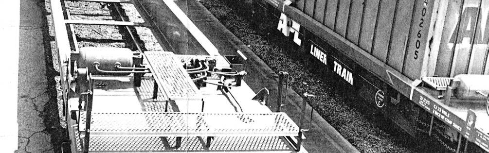
1 THRALL 5-UNIT ARTICULATED WELL CAR DIY MODELS W. Canyon Creek Dr. Maricopa, AZ DIMENSIONS Length End Units /16 Width (Inside Well at Bottom) 8-1 3/4 Length, Inter. Units / /2 Over Top Chords Length Over Coupler Pulling Faces /2 Between Top Chords Length Over Strikers /8 Length (Inside Well at Bottom) 40-2 WEIGHT Light Weight (Inter. Unit) 31,400 lbs. Capacity Per Unit 126,100 lbs. DAVID ALLEN Page 1 04/24/10
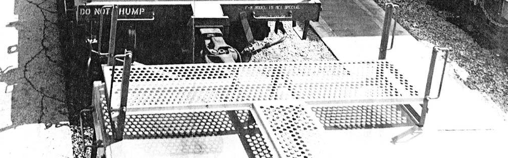
2 2 DIY MODELS THRALL 5-UNIT ARTICULATED WELL CAR Trailer-On-Flat-Car (TOFC) and Container-On-Flat-Car (COFC) have become a large business for the transportation industry. Shipping lines and truckers as well as the railroads have worked to make this an effective way to handle and transport goods. Containers especially lend themselves to intermodal transport since they are rectangular, have no wheels or other external components; therefore they can be stacked in multiple layers aboard ship. Railroads adapted 89-foot flatcars to carry this cargo inland from ports. This is often done with the unit train concept direct from point A to point B with a minimum of yard switching. In search of greater efficiency, shippers and railroads worked together to find a better method. Southern Pacific designed and American Car and Foundry (ACF) built a group of 5-unit cars articulated to become one car as the railroads look at it. These cars are capable of carrying 35 or 40- foot containers in a stack of two per unit, hence the trade name Double Stack. These cars have an empty weight of about 40,000 lbs. per platform. Since APL was seeking to maximize the efficiency of container carrying railcars, they pursued methods of weight reduction. It was apparent that if they eliminated the bulkheads of the ACF car, a significant weight reduction would be obtained. The only purpose of the bulkheads on the ACF cars was to keep the upper container on the car. Through the use of a prototype car designed and built by the Budd Co. (Lo-Pac 2000) to be used as TOFC and COFC both, APL was able to test the practicality of stacking containers two high by using inter-box connectors which are similar to the ones in use for stacking containers above deck aboard ship. Once this method was determined to be successful, APL in conjunction with Budd and the Thrall Car Co. designed a lightweight well-type railcar, which has become the APL Liner Train of today. The end platforms are capable of carrying two 20 foot containers in the well with a 40 or 45 foot container on top. The intermediate platforms are built to accommodate only a 40 foot container in the well with either a 40 or 45 foot container on top. These cars have an empty weight of about 31,000 lbs. per platform. Initially, 3 trains were obtained with 2 of them operating from Los Angeles to Chicago via UP and CNW and the other from Seattle to the East Coast via Conrail east of Chicago.. Other trains have since been obtained and are running from Los Angeles through Houston and New Orleans via SP and on to Atlanta via the Southern Railway. Trailer Train Corporation has recently acquired Thrall units and will run from the Northwest toward the East. Another modification to the Thrall unit is to add a diesel engine, generator and fuel tank to one of the end units with electrical connections to the other units to provide power for refrigerated containers. These units are painted red as compared to blue for the standard units. All have white lettering. Each unit of a car carries the same road number with a letter suffix (A through E). The relationship of the units is B-C-D-E-A so the railroad practice of an A and B end is maintained. Units A and B have conventional couplers and units A,B and D have air brake equipment. On the reefer units, the power equipment is on the A unit.
3 3 DIY MODELS GENERAL CONSTRUCTION NOTES Construct the two end units, A and B, which is the minimum possible configuration. You may also construct any inner unit( C,D or E). In the instructions, which follow, references will be made to end units and inner units as there are some slight differences in detailing. The Bill of Material list the sizing of most pieces are easily cut with a chopper or with a hobby knife. Slight trimming may be necessary to insure a close neat fit with a file or sandpaper. Since there are many small parts, fit the parts before cementing. Study all drawings and written instructions carefully before you start construction so you have a good overall idea of the car and its construction. Liquid plastic cement is strongly recommended; do not use the tube type plastic cement as it does not dry rapidly and could also spoil some areas of fine detail. Some type of super glue is also suggested to bond metal parts to the styrene. Observe all caution notices on any type of cement or solvent. A good work surface for working with styrene is Formica, wood, or glass since the solvent does not affect those surfaces directly. A straight edge fastened to the work surface is handy in squaring joints such as fastening the side panels to the bottom frame assembly. CONSTRUCTION 1. Assemble the bottom frame from two pieces of (A) and two cross pieces (B) using the plan view on Dwg. 1 fig A. Next, insert the other crosspieces as per the plan. When this assembly is thoroughly dry, sand all surfaces lightly. 2. Attach side panels(d) to the side sills ( C ) for end units or (L) for inner units). The narrower edge of the side sill should attach to the edge of the side panel as in Dwg. 1 fig D. The lengthwise positioning of the sill to the panel is shown in Dwg.. 1 fig C. When dry sand surfaces lightly. 3. Fasten the side panel assemblies to the outer edges of the bottom frame. Make sure the ends of the side panels are flush with the ends of the bottom frame. Insert the box ends ( G) between the side panels so they sit on.top. of the bottom frame and form a flush fit with the ends of the side panels. Trim to fit as necessary. Attach the two bottom plates (J) as per Dwg.. 1 fig 13. A semi-exploded view of the basic car body is shown in Dwg. 2 fig A. 4. Insert the end platforms (E) for a short end or (F) for long end) between the protruding side sills so the top of the platform is flush with the tops of the side sills and butting up against the previously installed box ends. When thoroughly dry, trim or sand the tops of the box ends flush with the platform tops. Then sand or trim the ends of the side sills and platforms to the same 1ength. 5. Create the male and female link components from.080 x.250 strips per the layout drawing. Cut the pieces to length and drill a hole in the male end for tapping for a 2-56 screw. Drill a clearance hole for a 2-56 screw in the female link. Each male link will have a truck attached with a long 2-56 screw provided with the screw protruding through the link so the opening in the female link will fit over it to act as the articulation joint. 6. Build up a bolster and draft gear support from.080 x.250 styrene. Attach coupler pockets to each long casting so the hole in the pocket lines up with the hole near the end of the casting. Kadee #5 couplers so the ears of the pocket must first be trimmed off. Sand the back of the pocket smooth and glue. Next sand the bottom of the black plastic bolster and fasten it to the cylinder on the long casting with super glue.
4 4 DIY MODELS 7. Laminate end strips (I) across each long end so the end of the deck and the ends of the side sills are covered. You will have to notch these strips accordingly so the top of, the strip is flush with the top of the platform. Do the same on all short ends using (I) strips. The ends are now neatly finished. 8. The vertical braces on each side panel are strips (K) and should be attached with care. The positioning of these is critical so that custom decals will fit between them properly. This positioning is shown in Dwg. 1 fig C. Now, taper these braces down from the edge of the side sill to the bottom of the side panel where they should be down to 1/32 thick. See Dwg. 1 fig D. This can be done with a flush cutter, file or sanding block but be careful not to mar any other surfaces. Lastly trim and sand the bottom of these braces so they are flush with the bottom frame of the car. This finishes the basic car body. Further detailing instructions are next and this will give the car much of its unique appearance. DETAILING 1. Detailing consists of adding steps, grabirons, and walkways and brake gear. Tools needed are drill bits (#53,76 and 78) to be used in pin vise or variable speed motor tool, pliers, screwdriver and wire cutters. All drilling should be done at this time before adding small bits of styrene details. Dwg. 2 fig A, Dwg. 3 fig B and Dwg. 4 contain information about the holes to be drilled. 2. When drilling is complete, attach grabirons and stirrup steps and fasten with super glue if desired. 3. Attach the walkway risers to the tops of the platforms as shown in Dwg. 4. The drawing is to scale - attach risers carefully, as the walkway will be cut to fit the locations of the risers. If this an A, B or D unit, attach air tank stands. When dry attach air tank, air valve but NOT brake wheel and stand. Use.015 wire to simulate air brake piping. See reference A in the photo for details. 4. For the B end unit only: Fabricate the brake chain hangers from.015 brass wire as shown in Dwg. 3 fig B. Construct the two brake chain pulley brackets from.125 x.015 and.040 x.030 stock provided. Shape the three pulleys from the 3/32 x.040 stock or. See Dwg. 3 fig A for details. Insert the wire hangers at this time. 5. Before fastening the above constructed brackets to the underside of the sill, drill two holes with #78 bit through the side sill from top to bottom as shown in Dwg. 3 fig C. Now attach the two brackets as shown and attach the third pulley to the side of the car body, and finish with the cover plate. Cut the piece of.008 brass wire in half and form the smallest possible hook in one end of each. Thread one of these hooks through the end link of the chain provided and then insert the straight end of the wire through the #78 hole nearest the car end. Pull through all the way and bend over sharply on top of the side sill. Fix in place with a spot of super glue, being careful not to let any drip onto the chain as it will become rigid immediately. When dry snip off the excess wire from the top of the sill. 6. Thread the chain through the pulley system in the manner shown in Dwg. 3 fig C. Finally using the second.008 wire hook, run it through an appropriate link in the chain and insert in the other #78 hole and finish it as described above.
5 5 DIY MODELS 7. The walkway material should now be prepared. Now refer to Dwg. 4 and the photo. Note that all walkways do not span the complete width of the car body. Dwg. 5 also shows more detail about the walkways. The lateral walkways nearest the ends of all units should be in line with the grabirons. On long ends of units A and B, walkways should stop 1/16 from each side. This leaves room to attach the upright grabs. On all other walkway locations, there will be an equipment box on the left side of one end and the right side of the other end. It is suggested that these equipment boxes be constructed before attaching the walkways. Use the small pieces (.250 x.125 x.015) for inner and outer edges and (.125 x.125 x.015) for the narrow ends of these boxes. The inner edge should attach directly to the walkway riser. The opposite end of these walkways should also stop 1/16 from the edge as above. 8. Small triangular pieces of styrene are used and cut into 1/16 long pcs. and used as load guides. All units have load guides on each side sill at the ends of the box opening. Units A and B also have these at the center of each side but before these are attached, the sill stiffeners should be applied. See Dwg. 1 fig B and C. 9. Cut the ladder stock as shown in Dwg. 4 fig B and D, sand the bottom edge flat and cement in place. A strip of.100 x.020 is cut into ¼ pcs and a #53 hole drilled nearest one end of each. You might perform this more accurately by drilling a #78 or #76 pilot hole first. These are the lift rings and should be attached as in Dwg. 1 fig C. Now attach a brake stand and wheel to the long end of the B unit directly above the chain pulley nearest the end. 10. This should complete the unit(s) and painting and decaling remains. Floquil Light Blue is a very close match for the entire APL car with Floquil Platinum Mist for the tops of the walkways. Prototype decals are available from Protopower Products. One sheet will do all five units of the car.

6 6 DIY MODELS
7 7 DIY MODELS Material for 2 End Units Des. Qty. Size Styrene sizes are for HO scale 40 Contnr. Length in scale feet 48 Contnr. Length in scale feet Description A x Bottom frame side strips B x Bottom frame cross pieces C 4.l00 x Side sills D x Side panels E x l-1/ Short platforms F x l-1/ Long platforms G x 3/ Well box ends H x Long platform end caps I x Short platform end caps J x Bottom end plates inside of well K x Side panel braces Detail Items Refer to Drawings for Location Item Qty. Size (decimal) 40 Well in scale feet 48 Well in scale feet Description Styrene triangular cross sect Load guides x Brake chain bracket base A/R.015 x Bracket sides.040 x Chain pulley material x Long walkway riser(tall) x.l Short walkway riser(low) x.l Air tank pedestals 2 Air tanks 2 Air valves x Equipment box sides x Equipment box ends 1 Brake wheel and stand x.l Lift ring plate material cut, the round end, drill hole 6 Ladder stock x See-through walkway if you re rich x Top side sill braces x Edge side sill braces 1 3/8 x 2-56 screws Used with center truck 2 ¼ x 2-56 screws Used with end trucks 3 Trucks Roller bearing type 2 Coupler box & Couplers x.250 Truck bolsters.125 x.250 x Grab irons - make from.015 music wire 12 Stirrup steps make from.015 music wire 1 8 pc.015 brass wire 1 2 pcs.008 brass wire 1 4 pcs. chain For brakes on B unit 1 Brake Stand & Brake Wheel
8 8 DIY MODELS Material for 3 Center Unit Frames De Qty. Size 40 Well in 48 Well in Description s. decimal scale feet scale feet A x Bottom frame side strips B x Bottom frame cross pieces C 6.l00 x Side sills D x Side panels E x l-1/ Short platforms G x 3/ Well box ends I x Platform end caps J x Bottom end plates inside of well K x Side panel braces Detail Items Refer to Drawings for Location Item No. Qty. Size (decimal) 40 Well in scale feet 48 Well in scale feet Description triangle? 1 1 Styrene triangular cross sect Load guides x Long walkway riser(tall) x.l Short walkway riser(low) x.l00 3/16 3/16 Air tank pedestals 1 Air tanks 1 on unit D 1 Air valves 1 on unit D x Equipment box sides x Equipment box ends x.l Lift ring plate material cut, the round end, drill hole 6 Ladder stock x See-through walkway if you re rich styrene otherwise! x Top side sill braces x Edge side sill braces 4 3/8 x 2-56 Used with trucks screws 3 Trucks Roller bearing type 12 Grab irons 12 Stirrup steps 1 8 pc.015 brass wire 1 Brake Stand 1 Brake Wheel
9 9 DIY MODELS Drawing 1
10 10 DIY MODELS Drawing 2 Deck Layouts
11 11 DIY MODELS
12 12 DIY MODELS
13 13 DIY MODELS
14 14 DIY MODELS

15 15 DIY MODELS
1. Underframe/Tank Bottom
 1. Underframe/Tank Bottom The construction process for the Class X tank cars is a little different as there is no true underframe. Instead we will use the tank bottom as part of the underframe, attaching
Instructions: GSC 60 Flatcar Kit with or without bulkheads Tangent Part Number: and /2016
 Instructions: GSC 60 Flatcar Kit with or without bulkheads Tangent Part Number: 11000-01 and 11000-02 5/2016 Thank you for purchasing the Tangent Scale Models GSC 60 Flatcar Kit! A few quick notes before
Instructions: PS-2CD 4000 Model Kit Revised 7/2008
 Instructions: PS-2CD 4000 Model Kit Revised 7/2008 Plastic Parts included: Body shell Parts Sprue #1 Roof, trainline, gravity outlet gates, and centersill/endsill pieces Parts Sprue #2 Underframe bolster
Instructions: Bethlehem 70 ton Riveted Gondola Kit
 Instructions: Bethlehem 70 ton Riveted Gondola Kit Kit number 10900 01 Steel Floor or 10900 02 Wood Floor 8/2012 Parts included in this kit: 95004 01 Plastic Part Body Shell (either steel or wood floor
CONCEPT MODELS SP DOUBLE STACK CONTAINER CARS INSTRUCTIONS Sheep Ranch Rd. Mountain Ranch, CA Web Address:
 CONCEPT MODELS Web Address: http://www.con-sys.com 8331 Sheep Ranch Rd. Mountain Ranch, CA 95246 SP DOUBLE STACK CONTAINER CARS INSTRUCTIONS 2 CONCEPT MODELS PARTS Item No. PART NO. DESCRIPTION QTY. 1
40 & 50 Foot PS-1 Box Car Assembly Instructions
 40 & 50 Foot PS-1 Box Car Instructions Push the #2100 coupler/stirrup assembly onto the ends of the metal floor. Slide them into the slots and slightly lift the ends (wings), then press firmly on the front
Scratch Build a Water Tower
 Here s some Prototype details Photos Courtesy of Rodney Doster Water Spout and Discharge Pipe Tank Bands Here s some more Prototype details Photos Courtesy of Rodney Doster Weather Vane as a Finial Using
Scratchbuild A Backwoods Water Tank Part V - Making the Frost Box and Hanging the Water Spout
 Scratchbuild A Backwoods Water Tank Part V - Making the Frost Box and Hanging the Water Spout By Dwight Ennis In this section, we're going to make the Frost Box, and we'll build the Spout Hanger Assembly
CONCEPT MODELS INSTRUCTIONS FOR PRODUCT 60,000 GALLON TANK CAR El Toro Way Stockton, CA 95210
 CONCEPT MODELS Web Address: http://www.con-sys.com Email: concept_models@con-sys.com 8810 El Toro Way Stockton, CA 95210 INSTRUCTIONS FOR PRODUCT 60,000 GALLON TANK CAR 2 CONCEPT MODELS PARTS GATX/UTLX
Precision Steel Car s 100 T Steel Coil Car
 Precision Steel Car s 100 T Steel Coil Car Precision Steel Car www.precisionsteelcar.com info@precisionsteelcar.com Paul Vernon: (513) 571-5739 Revised 4/30/2009 Contents of Kit Main Tube Side Frame 2
PS 5077 cu. ft. Boxcar with EOC device. 1:29 scale resin craftsman kit. by Burl Rice
 PS 5077 cu. ft. Boxcar with EOC device 1:29 scale resin craftsman kit by Burl Rice www.burlrice.com Bill of materials (not included): Thick/medium viscosity CA PL adhesive, or Gorilla Glue Heavy Duty Construction
CONCEPT MODELS INSTRUCTIONS FOR THE KASGRO KRL SPECIAL DEPRESSED CENTER FLAT CARS El Toro Way Stockton, CA 95210
 CONCEPT MODELS Web Address: http://www.con-sys.com Email: concept_models@con-sys.com 8810 El Toro Way Stockton, CA 95210 INSTRUCTIONS FOR THE KASGRO KRL 204000-2 SPECIAL DEPRESSED CENTER FLAT CARS 2 CONCEPT
Peter Krause ABN
 Peter Krause ABN 25 736 637 163 T/as O-Aust Kits PO Box 743 ALBANY CREEK QLD 4035 AUSTRALIA Phone +61 (0)7 3298 6283 (7.00pm to 9.30pm ONLY) Facsimile +61 (0)7 3298 6287 (24 hours) Mobile 0419 680 584
20 ORE CAR INSTRUCTIONS. Kit )rv \M TAURUS PRODUCTS P.0. BOX 6534 ORANGECA m WeWWW. Dronerty efi N456 Inc.
rv \M TAURUS PRODUCTS P.0. BOX 6534 ORANGECA m WeWWW. Dronerty efi N456 Inc.") 20 ORE CAR Kit 3305 - INSTRUCTIONS TAURUS PRODUCTS )rv \M P.0. BOX 6534 ORANGECA. 92667 m WeWWW Dronerty efi N456 Inc. Thank you for selecting this TAURUS PRODUCTS kit. We sincerely hope that you will
20 ORE CAR Kit 3305 - INSTRUCTIONS TAURUS PRODUCTS )rv \M P.0. BOX 6534 ORANGECA. 92667 m WeWWW Dronerty efi N456 Inc. Thank you for selecting this TAURUS PRODUCTS kit. We sincerely hope that you will
Kit 6.00 ACF Type 27, Class ,000 Gallon Insulated Tank Cars
 Kit 6.00 ACF Type 27, Class 103 10,000 Gallon Insulated Tank Cars Introduction Warranty Thank you for your interest in Resin Car Works and this kit. Resin Car Works is not a business in the traditional
28 ft. Ventilated (Combination) Box Car
 Box Car") 28 ft. Ventilated (Combination) Box Car Introduction This laser cut wood kit is an HO scale model of a 28 ft. Ventilated (also known as a Combination) Box Car. The model is based on the Illinois Central
28 ft. Ventilated (Combination) Box Car Introduction This laser cut wood kit is an HO scale model of a 28 ft. Ventilated (also known as a Combination) Box Car. The model is based on the Illinois Central
CONCEPT MODELS UTLX 80006,80020 CRYOGENIC TANK CAR KIT INSTRUCTIONS Sheep Ranch Rd. Mountain Ranch, CA 95246
 CONCEPT MODELS Web Address: http://www.con-sys.com Email: concept_models@con-sys.com 8331 Sheep Ranch Rd. Mountain Ranch, CA 95246 UTLX 80006,80020 CRYOGENIC TANK CAR KIT INSTRUCTIONS 2 CONCEPT MODELS
SE5a Instrument Board part 2 - rev 1.1
 SE5a Instrument Board part 2 - rev 1.1 Fuel (Petrol) Valve This valve uses two circular name plates, eight brass screws, one black plastic base, copper wire and two black plastic risers. You can pick any
Southern Pacific C-30-4/6 Bay Window Caboose N-Scale & HO-Scale
 Southern Pacific C-30-4/6 Bay Window Caboose N-Scale & HO-Scale Before Starting PREPARING BRASS The easiest way to remove the brass parts from the sheet they are produced on, is to use rail nippers. The
HOn3-118 Denver, Boulder & Western Box Car
 HOn3-118 Denver, Boulder & Western Box Car 30 32 35 29 28 34 Door and Track on End Opposite Brake Wheel ONLY 31 3 36 2 6 24 33 Deadwoods Center Line of Coupler 27 We would like to thank you for purchasing
Tools and Tips: ( 1 )
") Tools and Tips: As you build instructions will show in my many picture manual how to assemble. You can use your own methods as you desire, my results are very good. A smooth, flat work surface is very
Tools and Tips: As you build instructions will show in my many picture manual how to assemble. You can use your own methods as you desire, my results are very good. A smooth, flat work surface is very
After the glue dries, trim the trussrod ends with your cutting pliers
 The following information and photographs are what I did to build the kit. Your methods and needs may differ from this which is fine. There is no right or wrong way if you are used to scratch building.
Instructions For Corrugated End Van
 Instructions For Corrugated End Van This kit contains the following items QTY ITEM QTY ITEM QTY ITEM 1 Floor 2 Van Ends 1 Roof 2 Van Sides 2 Sole Bars 4 Axle Boxes 4 Bearings 2 Coupling Hooks 2 Split Pins
Lima XPT/HST Re-Powering Conversion
 Lima XPT/HST Re-Powering Conversion Please read through these instructions before beginning the conversion process. Non-Powered Bogie The front non-powered bogie is the starting point for this conversion.
EXTREME LOAD no. TWO
 1602 - EXTREME LOAD no. TWO Kit Features: 22' 4 " x 14' x 3'-6 Oversize Load 49mm (1.9") actual height Bolt Head Details Welded Load Mounting Fins Painting Handles Tools Required: Hobby Knife Tweezers
Trim down the piece of casting being pointed to with the tip of the pencil in the first picture. It is only the 'inboard casting that needs to be
 1. File off the moulding pips from the wheel flanges. File the ends of the tube smooth and de-burr. Assemble the wheel sets with a drop of car engine oil on the axles. Glue the wheel sets into place. 2.
Dura-Lock Roof System
 DLR-14 Dura-Lock Roof System Assembly and Installation Instructions Read the instructions before starting the job. They explain the steps required to produce a finished product that will meet factory specifications.
PORTA-DOCK, INC. AP17 APD DS 4 X 16 T12 AW17 CPD DS 4 X 16 T12
 Page 1 of 7 PORTA-DOCK, INC. AP17 APD DS 4 X 16 T12 AW17 CPD DS 4 X 16 T12 *For Beige Decking Add the Letter B to Model* Thank you for purchasing out product! *Please read these instructions and follow
MobileTrak5 Installation Instructions
 MobileTrak5 Installation Instructions PLEASE OPEN ALL BOXES & CHECK TO MAKE SURE YOU HAVE ALL PIECES REQUIRED READ ALL INSTRUCTIONS BEFORE STARTING Tools Required for Assembly 7/16, 1/2 Wrench Phillips
129 KITCHEN BASE CABINET 480
 129 KITCHEN BASE CABINET 480 There are two sorts of kitchen cabinets: base cabinets, which sit on the floor, and wall cabinets. Base cabinets provide both storage space and work surfaces. They often house
INSTALLATION GUIDE. TRANZFORM Sound TRANZFORM Space
 INSTALLATION GUIDE TRANZFORM Sound TRANZFORM Space Cornell Iron Works, Inc. 100 Elmwood Ave. Crestwood Industrial Park Mountain Top, PA 18707 Phone: 800.233.8366 or 570.474.6773 Fax: 800.526.0841 INSTALLATION
Thank you for purchasing out product! *Please read these instructions and follow them step by step. *
 Page 1 of 7 AD17 AA DS 4 X 16 T12 Thank you for purchasing out product! *Please read these instructions and follow them step by step. * STEP 1. Slide two support posts (REF. # 24) into the two outside
Nanton Grain Mill Assembly
 ( 1 ) Nanton Grain Mill Assembly Locate package for assembling storage building. These are cut from 1/8 masonite. Inspect and lightly sand edges where it will be bonded. Use white glue or CA glue to bond.
Installation Instructions For Slider Casement Air Conditioners
 Installation Instructions For Slider Casement Air Conditioners NOTE: These instructions describe installation in a typical wood framed window with a wood SLIDE-BY sash, or installation in a metal CASEMENT
VICTORIAN RAILWAYS GY WAGON
 C/- P.O. Rhyll, Victoria, 3923. VICTORIAN RAILWAYS GY WAGON Prototype Notes The GY wagon fleet was one of the largest single classes of goods vehicle in VR service and was primarily a bulk commodities
Installing Body Mounted Kadee Couplers on LGB Housecars
 Installing Body Mounted Kadee Couplers on LGB Housecars Steven C. Seitel Before (left) and after (right) This easy conversion replaces the stock hook and loop couplers on the LGB housecars with Kadee knuckle
Continue gluing the remaining top parts ensuring the angled piece is glued well. Set aside and let dry. See photo below
 Radiator rev 1.1 The SE5a s radiator is one of the most recognized radiators in WW1. It is one of the components that defines the SE5a. The original SE5a has seen multiple radiator designs used during
CA to each one. You may have to hold the end down while to glue sets or use an accelerator like I did.
 The following information and photographs are what I did to build the kit. Your methods and needs may differ from this which is fine. There is no right or wrong way if you are used to scratch building.
THE SWALLOW. An interesting, simple, all-balsa speedster of crashproof design. by MALCOLM J. ABZUG
 THE SWALLOW An interesting, simple, all-balsa speedster of crashproof design. by MALCOLM J. ABZUG DESIGNED primarily for the purpose of testing a new type of monocoque fuselage design, the Swallow proved
Precision Steel Car s 40 Ft. Stock Car
 Precision Steel Car s 40 Ft. Stock Car Precision Steel Car Website: www.precisionsteelcar.com E-mail: info@precisionsteelcar.com Revised 12/3/2018 Paul Vernon: (513) 571-5739 PSC 40 ft. Stock Car Kit:
CONCEPT MODELS INSTRUCTIONS FOR UP DC-10 WING CAR El Toro Way Stockton, CA Web Address:
 CONCEPT MODELS Web Address: http://www.con-sys.com 8810 El Toro Way Stockton, CA 95210 INSTRUCTIONS FOR UP DC-10 WING CAR 2 CONCEPT MODELS PARTS DC-10 WING CAR Item No. Part No. DESCRIPTION QTY. 1 2003-1
After the glue dries, trim the trussrod ends with your cutting pliers.
 The following information and photographs are what I did to build the kit. Your methods and needs may differ from this which is fine. There is no right or wrong way if you are used to scratch building.
VICTORIAN RAILWAYS QR BOGIE OPEN WAGON
 C/- P.O. Rhyll, Victoria, 3923. VICTORIAN RAILWAYS QR BOGIE OPEN WAGON Prototype Notes QR number 1 was built at the VR Newport workshops in 1889, being the forerunner of a long lived and useful class of
SCHWERE PLATTFORMWAGON TYPE SSY 60TON
 TWS 5094 SCHWERE PLATTFORMWAGON TYPE SSY 60TON Congratulations on purchasing one of the finer aftermarket resin kits sets available. The photo below is of the completed kit. The Panther tank is not included
Tortoise Switch Machines, Mounted Horizontally
 Tortoise Switch Machines, Mounted Horizontally by David King Have you ever used the Tortoise Switch Machines manufactured by Circuitron. These are a wonderful stall motor slow motion switch machine that
the wire, less is better. And make sure the bends on each truss wire are in line with the other. See the next photo.
 The following information and photographs are what I did to build the kit. Your methods and needs may differ from this which is fine. There is no right or wrong way if you are used to scratch building.
C-180 Builder s Manual
 C-180 Builder s Manual. May 20, 2002 Last revised July 11, 2002 Copyright! 2002 Douglas Binder, Mountain Models www.mountainmodels.com sales@mountainmodels.com (719) 630-3186 1 Required Equipment! Xacto
O-Aust Kits. QR Class CLF Louvred Wagon Kitset in O Scale 1:48
 O-Aust Kits PO Box 743 ALBANY CREEK QLD 4035 AUSTRALIA Phone +61 (0)7 3298 6283 (7.00pm to 9.30pm ONLY) Facsimile +61 (0)7 3298 6287 (24 hours) Mobile 0419 680 584 Email pa_rl_krause@bigpond.com Web www.oaustkits.com.au
Clearview Railing System Installation Instructions
 Clearview Railing System Installation Instructions Disclaimer: AGS Stainless, Inc. has its Clearview Railing Systems designed by a professional engineer to meet the requirements of the latest national
FINNEY7 4500G May17 SR 4500G TENDER. Fig 1. Original Appearance. Side raves Sanding gear Front water fillers TIA Water treatment system
 Fig 1. Original Appearance Side raves Sanding gear Front water fillers TIA Water treatment system 4500G - 3 Fig 2. Rebuilt Condition Cut down side raves with fire iron tunnels# TIA removed and replaced
CUT OUT FLARES INSTALLATION INSTRUCTIONS FOR 20017, 20018, F100-F150 F250-F350 P.U. & BRONCO CUT OUTS
 20017 04/22/03 REV-A CUT OUT FLARES INSTALLATION INSTRUCTIONS FOR 20017, 20018, F100-F150 F250-F350 P.U. & BRONCO CUT OUTS Tools Required for Installation: (A) 3/16 Drill Bit (B) Pop-Rivet Gun (C) Air
Application Note. Con-Cor Goose Tsunami Digital Sound Decoder Installation Notes
 Application Note Con-Cor Goose Tsunami Digital Sound Decoder Installation Notes Overview This application note describes how to install a TSU-750 Digital Sound Decoder into a Con-Cor HO Goose. Skill Level
The Rubley Building Instructions for Assembly of the N scale kit. v1.1
 The Rubley Building Instructions for Assembly of the N scale kit. v1.1 Kit Contents: 197 ea. laser cut 1/16" acrylic parts. 1ea. adhesive backed.020 styrene part. 10 ea..060 x 1" styrene alignment pins.
NSWGR Class SRC Refrigerated Wagon Kitset in 7mm Scale
 O-Aust Kits PO Box 743 ALBANY CREEK QLD 4035 AUSTRALIA Phone +61 (0)7 3298 6283 (7.00pm to 9.30pm ONLY) Facsimile +61 (0)7 3298 6287 (24 hours) Mobile 0419 680 584 Email pa_rl_krause@bigpond.com Web www.oaustkits.com.au
Installation Instructions
 READ BEFORE INSTALLING UNIT For Slider Casement Air Conditioners To avoid risk of personal injury, property damage, or product damage due to the weight of this device and sharp edges that may be exposed:
Removing and Replacing the Y-truck
 Service Documentation Removing and Replacing the Y-truck To remove and replace the Y-truck you will need the following tools: 4mm Allen wrench 12mm stamped flat wrench #2 Phillips screwdriver (magnetic
Application Note. Bowser-Stewart VO-1000 Tsunami Digital Sound Decoder Installation Notes
 Application Note Overview This application note describes how to install a TSU-1000 Digital Sound Decoder into the Bowser-Stewart VO-1000 Locomotive. Skill Level 4: The entire installation can be completed
CHEVY/GMC SuperRail Mounting Kit #3117
 CHEVY/GMC SuperRail Mounting Kit #3117 #3100 SuperGlide (12K) Gross Trailer Weight (Maximum) Vertical Load Weight (Max. Pin Weight) 12,000 lbs. 3,000 lbs. Installation Instructions SPECIFICATIONS Fits
Leafy Greens Spinner Construction Manual
 Leafy Greens Spinner Construction Manual University of Houston Conrad N. Hilton College Food Science Lab Materials list: Base and Armature Approximately 8-1 PVC cut into sections o 3-22.5 o 2-7 o 2-4 o
Kentucky 4H Wood Science Plans Notebook. Plans Level 3
 Kentucky 4H Wood Science Plans Notebook Plans Level 3 MATERIALS: 2 pieces wood 3/4 x 10 x 4 1 piece wood 3/4 x 12 x 4 2 pieces wood 3/4 x 3 x 2 5 1/2" 2 pieces wood 3/4 x 3 x 1 8 1 piece wood 2 x 4 x
Note - the nose ribs and are thinner than the main ribs. These nose ribs will use a thinner rib cap than the ribs. This is per design.
 Stabilizer rev 1.2 The SE5a stabilizer is the heartbeat of the tail and is recreated like the full scale version. All tail pieces depend on the stabilizer. It uses the steel fittings, pulleys, inspection
Installation Instructions
 DODGE 16K Industry Standard Rail Custom Mounting Kit #2728 Gross Trailer Weight (Maximum)...16,000 lbs. Vertical Load Weight (Max. Pin Weight)...4,000 lbs. SYSTEM TOW CAPACITY Please note, in order to
American Car and Foundry Type 27 ICC Class 103A & B 7000 and 8000 Gallon Acid Tank Cars
 American Car and Foundry Type 27 ICC Class 103A & B 7000 and 8000 Gallon Acid Tank Cars Introduction Thank you for your interest in Resin Car Works and this kit. Resin Car Works is not a business in the
Installation Instructions for Vista Air Vertically Folding Walls
 Installation Instructions for Vista Air Vertically Folding Walls Use these instructions in conjunction with your shop drawings to see the specifics that are particular to the model you are installing.
Bowser Baldwin AS-16 Tsunami Digital Sound Decoder Installation Notes
 Bowser Baldwin AS-16 Tsunami Digital Sound Decoder Installation Notes Overview This application note describes how to install a TSU-BW1000 digital sound decoder into a Bowser HO Baldwin AS-16. Skill Level
Adding Buffers to the SEM Z van
 Adding Buffers to the SEM Z van Throughout the 1930s, 40s and early 50s the Victorian Railways carried out a program of conversion of rolling stock to auto couplers, with a particular emphasis on goods
Application Note. Athearn RTR AC4400CW Tsunami Digital Sound Decoder Installation Notes
 Application Note Overview This application note describes how to install a TSU-AT1000 Digital Sound Decoder into an HO Athearn Ready To Roll AC4400CW. Skill Level 2: The entire installation can be completed
Cardo DOOR & RETURN SHOWER ENCLOSURE INSTALLATION PLEASE READ THESE INSTRUCTIONS CAREFULLY.
 Cardo DOOR & RETURN SHOWER ENCLOSURE INSTALLATION PLEASE READ THESE INSTRUCTIONS CAREFULLY. IT IS RECOMMENDED TO USE A TRAINED SHOWER INSTALLER FOR THIS SHOWER TO OBTAIN THE BEST INSTALLATION. D Square
-1- Coach Instructions.
 -1- Coach Instructions. Insert the bogie pivot pins through the bottom of the coach body ensuring the dimples fit into the recesses. Glue the.06 x.25 short strips each side of the pivot head, bridge the
FUSELAGE CONSTRUCTION
 FUSELAGE CONSTRUCTION Note: prior to building and gluing on the work surface use protective covering on your building surface. (wax paper or clear wrap) Fit the laser cut Fuselage Front and Fuselage Rear
Athearn RTR AMD103/P42 Tsunami Digital Sound Decoder Installation Notes
 Athearn RTR AMD103/P42 Tsunami Digital Sound Decoder Installation Notes Overview This application note describes how to install a TSU-AT1000 into an Athearn HO Ready-To-Roll GE AMD103/P42. Skill Level
Flat Style Fender Flares Front Pair. Jeep. Included in Hardware Kit:
 Jeep Flat Style Fender Flares Front Pair STEP 1 PRIOR TO INSTALLATION A) Bushwacker only approves installing the fl ares according to these written instructions with the hardware provided. WARNING: Failure
V4 Premium Kit. Prusa i3 Build Guide
 V4 Premium Kit Prusa i3 Build Guide Hi! Congratulations on your purchase of the DIYElectronics.co.za Prusa I3 kit, the best South African 3D Printer Kit! Hopefully this should serve as complete guide to
CHEVY/GMC SuperRail Mounting Kit #4423
 CHEVY/GMC SuperRail Mounting Kit #4423 #4100 SuperGlide (16K) #4400 SuperGlide (20K) Gross Trailer Weight (Maximum) Vertical Load Weight (Max. Pin Weight) 16,000 lbs. 4,000 lbs. Gross Trailer Weight (Maximum)
OPERATION AND MAINTENANCE FOR MODEL MRV050A REVERSIBLE
 OPERATION AND MAINTENANCE FOR MODEL MRV050A REVERSIBLE MANUAL AIR MOTOR 04666770 Edition 1 April, 1999 IMPORTANT SAFETY INFORMATION ENCLOSED. READ THIS MANUAL BEFORE OPERATING TOOL. FAILURE TO OBSERVE
400A 40113V, 401A 40120V, & 401AL 40120VL ALUMINUM VERTICAL 4000 LB LIFT INCLUDES SCREW LEG ASSEMBLY INSTRUCTIONS
 12/11/07 PAGE 1 OF 12 400A 40113V, 401A 40120V, & 401AL 40120VL ALUMINUM VERTICAL 4000 LB LIFT INCLUDES SCREW LEG ASSEMBLY INSTRUCTIONS Thank you for purchasing our product! *Please read these instructions
The Festival Assembly Instructions
 The Festival Assembly Instructions Toll Free: 866.768.8465 Hours: 9-5 Monday-Friday EST www.homeplacestructures.com Package ships as shown CONTACT INFORMATION: HomePlace Structures 301 Commerce Drive New
N Scale Concrete Coal Dock Instruction Manual
 N Scale Concrete Coal Dock Instruction Manual 1. General Overview This kit combines precision laser cut acrylic, photo etched brass and wood parts to make a highly detailed model of the Roberts and Schaefer
Installation Instructions
 DODGE RAM 2500 20K Industry Standard SuperRail Custom Mounting Kit #2336 Gross Trailer Weight (Maximum)...20,000 lbs. Vertical Load Weight (Max. Pin Weight)...5,000 lbs. SYSTEM TOW CAPACITY Please note,
LEG CURL IP-S1315 INSTALLATION INSTRUCTIONS
 LEG CURL IP-S35 INSTALLATION INSTRUCTIONS Copyright 2009. Star Trac by Unisen, Inc. All rights reserved, including those to reproduce this book or parts thereof in any form without first obtaining written
Ford Cut-Out Fender Flares Rear Pair
 Ford Cut-Out Fender Flares Rear Pair STEP 1 PRIOR TO INSTALLATION A) Bushwacker only approves installing the fl ares according to these written instructions with the hardware provided. WARNING: Failure
Series 1500 Aluminum Door Canopy
 Series 500 Aluminum Door Canopy with Sidewings It is our recommendation that you read instructions carefully prior to assembly and installation. Series 500 with Sidewings mounting bar (A) top trim (B)
Kits SE #1.1 and SE #1.2 GATX Type 30 Class 103 8,000 Gallon Tank Car
 Kits SE #1.1 and SE #1.2 GATX Type 30 Class 103 8,000 Gallon Tank Car Introduction Thank you for your interest in Resin Car Works and this kit. Resin Car Works is not a business in the traditional sense.
Woodchip Loader All Scales
 Woodchip Loader All Scales Before Starting PREPARING BRASS The easiest way to remove the brass parts from the sheet they are produced on, is to use rail nippers. The brass is soft and won't affect their
The Virgo/Libra Steam Engine
 The Virgo/Libra Steam Engine Congratulations on becoming the owner of a Virgo or Libra Steam Engine. With careful use and maintenance it will give many years of satisfying performance. Contents 1) Notes
You can print these instructions by downloading the PDF here: Boxcar Assembly PDF
 The following information and photographs are what I did to build the kit. Your methods and needs may differ from this which is fine. There is no right or wrong way if you are used to scratch building.
FORWARD FUSELAGE SIDES & REAR TOP SKINS
 FORWARD FUSELAGE SIDES & REAR TOP SKINS WORK REPORT Step No. Check Parts / Tools Qty Preparations. 1 [ ] 6F5-3 Upper Front Longerons 2 2 [ ] 6F5-5 Heel Support 1 3 [ ] 6F5-2 Front Floor Skin 1 3 [ ] Firewall
INSTALLATION AND CARE INSTRUCTIONS
 INSTALLATION AND CARE INSTRUCTIONS Skylight Manually Operated Honeycomb Shades 20 C8-10-1806 2/15 1 INTRODUCTION Thank you for purchasing our product. Your new shade has been custom built for you from
Ford Ranger / Bronco II Set Part # Rev B 5-04
 Ford Ranger / Bronco II Set Part # 21008 Rev B 5-04 Step 1: Prior to Installation: A) Fit: Verify the fit of the flares to vehicle. (Some filing, sanding, or cutting may be necessary to ensure proper fit).
Shay Tender Frame Fabrication
 Shay Tender Frame Fabrication Nelson Riedel Nelson@NelsonsLocomotive.com Initial:3/15/03 Last Revised: 06/05/2004 This page shows additional detail on the tender frame members and some of the processes
IMPULSE G2/PULSE STATIC BRIDGE & RETURN MODULE. Drill. Desk Connecting. Outside by fastening the supplied wood screws from the HK-67 kit through the
 PART # 1608990 STATIC BRIDGE & RETURN MODULE 1. This sheet covers the steps to install a static bridge or return module with the FX no hinged access panel back option to a height adjustable freestanding
Parts list Instruction guide Warnings Please read carefully before assembling and using product.
 Parts list Instruction guide Warnings Please read carefully before assembling and using product. Jet Rail XL Part Number 27377 Tools required for assembly Hammer 9/16 Wrench 3/4 Wrench Ratchet 9/16 Socket
136 PLYWOOD DESK 522
 136 PLYWOOD DESK 522 Simple in design and inexpensive, this plywood desk is made from a single 4- x 8-foot panel. Plywood is available with many hardwood veneers; it can also be covered with plastic laminate,
Depending on the size you ordered you will have either 5 Foot sections which will build the 10 Foot frame or 6 Foot sections which will build the 12
 XL Quilting Frame 1 Depending on the size you ordered you will have either 5 Foot sections which will build the 10 Foot frame or 6 Foot sections which will build the 12 Foot frame Printed 2 June 2014 Updated
Tools and Tips: ( 1 )
") Tools and Tips: As you build the book will show in my many picture manual how to assemble. You can use your own methods as you desire, but these worked best for me. A smooth, flat work surface is very
Tools and Tips: As you build the book will show in my many picture manual how to assemble. You can use your own methods as you desire, but these worked best for me. A smooth, flat work surface is very
Field of Armor. 1/6th SCALE TIGER 1 MODEL TANK INSTRUCTIONS
 Field of Armor 1/6th SCALE TIGER 1 MODEL TANK INSTRUCTIONS Items needed for construction: - Well ventilated, clean 4' x 4' working space - 1 can black or clear ABS Glue (available in plumbing section of
Insolroll Clutch Operated Shades Installation Instructions Installation Instructions
 All clutch operated shades are shipped fully assembled and ready for installation. Mounting screws are not provided. Screws for chain guide installation to meet the child safety standards are provided.
PITTS S2S CONSTRUCTION
 PITTS S2S CONSTRUCTION FUSELAGE CONSTRUCTION 1) Place the right fuselage side over the plan and mark the former positions. Place the left side over the right side and mark the former positions. Glue F1
Building Instructions Diva cabin boat
 Building Instructions Diva cabin boat Order no. 3093/00 aero-naut Modellbau Stuttgarterstr. 18-22 D-72766 Reutlingen / Germany http://www.aero-naut.com 1 For pictured building instructions please see the