Application Note. Con-Cor Goose Tsunami Digital Sound Decoder Installation Notes
|
|
|
- Chloe Banks
- 6 years ago
- Views:
Transcription


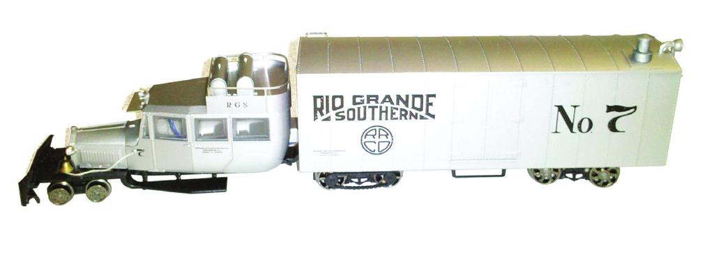
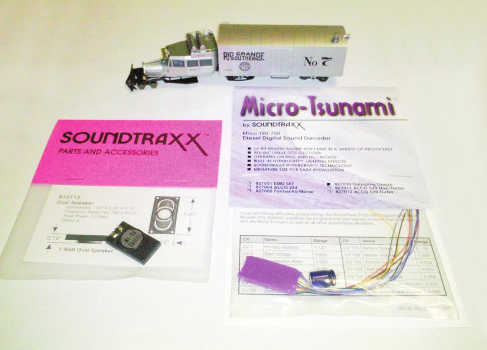
1 Application Note Con-Cor Goose Tsunami Digital Sound Decoder Installation Notes Overview This application note describes how to install a TSU-750 Digital Sound Decoder into a Con-Cor HO Goose. Skill Level 3: One to three hours installation requiring working in tight spaces and some minimal modifications to the model. Bill of Materials P.N. Description TSU-750 for Galloping Goose 14mm x 25.5mm Oval Speaker Golden-White LED 6-Pack Shrink Tube Assortment One 1k Ohm, 1/8 Watt Resistor Evergreen P.N Sheet Styrene 3/16 Styrene Tubing For your convenience, Evergreen part numbers have been listed above. Please visit their website at Tools You Will Need #60 Drill Bit Pin Vise or Small Electric Drill X-Acto Knife Soldering Iron Rosin Core Solder Aquarium Sealant / Silicone Miniature Screwdriver Set Flush Cutting Pliers Wire Cutters Double-Sided Foam Tape Liquid Plastic Cement (Tenax 7R or equivalent) Heat Gun or Blow Dryer


 Photo 2 2.")

 T- TFL+ FL- M+ M- T+ M = Motor FL = Front Light (Headlight) T+ = Track Positive (Red Wire) T- = Track Negative (Black")
2 Installation Start by removing the cargo box shell. Gently slide a small flat screwdriver under the side of the box to free the tabs and then lift the cargo box off the frame. This will reveal the factory installed circuit board. (Photos 1 and 2) Remove the wires from the circuit board. Pull the black caps off the terminals holding the wires in place and pull the wires out of the holes in each tab. (Photo 3) Photo 1 Photo 3 4. Remove the screws located in the front left corner and the rear right corner of the circuit board. Lift the circuit board out of the model. (Photo 4) Photo 2 2. Using Figure 1 below, note the markings on the circuit board for the M+ and M- motor leads, the + and - track pickup wires, and FL for front light. Label the wires connected to these with tape if needed. The backup light is part of the circuit board and will be replaced in a later step. (Figure 1) T- TFL+ FL- M+ M- T+ M = Motor FL = Front Light (Headlight) T+ = Track Positive (Red Wire) T- = Track Negative (Black Wire) T+ Photo 4 5. Locate the blue and the green wires on the Tsunami. These will be connected to the capacitor. Cut the blue wire about 2 from the end. Strip 1/8 insulation from the end of the blue wire and one end of the 2 piece cut from the blue wire. Twist the ends together. (Photo 5) Figure 1 Photo 5

 Photo 6 7.")

3 6. Slide a 1/2 piece of 3/64 heat-shrink tubing over the blue wires and a a 1/2 piece of 3/64 heat-shrink tubing over the green wire. Solder the twisted blue wires to the positive lead of the capacitor and the green wire to the negative lead. The negative lead of the capacitor is designated by the light blue stripe with a minus sign. After soldering these connections, pull the shrink tubing over the joints and shrink the insulating tubing with a heat source. (Photo 6) Photo 6 7. Next, join the track pickup wires to their respective red and black wires. Twist the right rail track leads together, and then twist the left rail track leads together. You should now have two branches. Slide a piece of 3/16 heat-shrink tubing over each pair of wires, then attach the Tsunami s red wire to the right rail branch and the Tsunami s black wire to the left rail branch. Solder the joints, then slide the tubing over the joint and shrink in place. Follow with the motor leads. The orange wire goes to the M+ wire, and the grey wire to the M- wire. (Photo 7) Photo 7 8. The Con-Cor Goose uses a 14V bulb for the headlight, so polarity is not important. Slide a 1/4 piece of heat-shrink tubing over the Tsunami s white wire and a 1/4 piece of heat-shrink tubing over the yellow wire. Cut 2 from one of the headlight wires and discard. Tin the end of the shortened wire and then solder to the Tsunami s white wire. 9. The backup light will be replaced with an LED. Polarity is important with LEDs, so first determine the negative lead. (An LED s negative lead can be determined by the shorter lead, or by the wider edge of the flag-shaped component in the LED.) Shorten the LED s leads to 1/2. Solder the Tsunami s yellow wire to the negative lead of the LED. 10. Slide a 1/2 piece of 1/4 heat-shrink tubing over both the Tsunami s blue wire and the remaining headlight wire. Solder both wires to one lead of a 1k ohm resistor. Cut off any excess length from the resistor lead. Shorten the remaining resistor lead to 3/8 and solder to the positive lead of the LED. Slide the heat-shrink tubing over the joints and shrink to insulate. (Figure 2 and Photo 8) Decoder Backup Light Decoder Function Common LED Locomotive Headlight 1K Resistor Figure 2 Photo Now take the model for a test run. Place the model on the mainline, select address 3, and check that the headlight, backup light and motor are all functioning properly.


4 12. Due to the heat that the motor and decoder generate, it is necessary to leave the opening originally designed for the speaker open, so we will relocate the speaker. It will be necessary to build a small speaker baffle using styrene. Use the dimensions for the baffle found at the end of this document as a pattern. Drill two small holes using the #60 drill bit on the marked piece. This side will be placed on the end nearest the speaker terminals. 13. Start by attaching one side of the enclosure to the speaker with liquid plastic cement. Then attach the next piece to the speaker side in the same manner. Follow this until all four sides are complete. (Photo 9) Photo Before closing up the enclosure, insert the Tsunami s two purple wires through the two holes, strip 1/8 insulation off and tin the ends. 15. Solder the two purple wires to the speaker terminals. Since we are using only one speaker, polarity is not important. (Photo 10) 17. Take the model for a test run by placing it on the mainline, selecting address 3, and testing the sound, lights, and motor function. 18. Now turn your attention to mounting the backup light. Cut a 1/4 piece off of the styrene tubing. The LED for the backup light should fit inside the tubing. Test for a clean fit first. The tubing is not always perfectly symmetrical inside, so some filing or drilling out of the inside may be necessary. 19. When you are finished adjusting the tubing to fit the LED, cement the tube to the inside of the cargo box just underneath the backup light casting (the clear plastic lens that extends through the shell to transmit light). After the cement dries, secure the LED inside the tubing using the clear silicone. Allow this to thoroughly dry for best results. 20. Using the double-sided foam tape, secure the speaker assembly to the roof of the cargo box toward the rear of the shell. Next, attach the TSU-750 to the side of the cargo box opposite the backup light casting. Be sure the flat side of the decoder is facing outward, as this is the heat sink and needs the best access to the air coming through the original speaker opening. 21. On the other side of the cargo box, attach the capacitor with double-sided foam tape. Be sure all of these components fit inside the shell as high as possible to ensure the frame has ample clearance. (Photo 11) Photo Attach the top of the baffle to the assembly with the plastic cement. Photo Now, reattach the cargo box by tucking in all loose wires and pressing it in place. All that is left is to explore the horn selection and have fun!
5 Baffle Dimensions TM New Dimensions in Digital Sound Technology 2013 Throttle Up! Corp. All Rights Reserved 141 Burnett Drive Durango, CO Phone: (970) Toll Free: Fax: (970) support@soundtraxx.com Website:
Atlas GenSet Tsunami Digital Sound Decoder Installation Notes
 Atlas GenSet Tsunami Digital Sound Decoder Installation Notes Overview This application note describes how to install a TSU-AT1000 digital sound decoder into an Atlas HO GenSet. Skill Level 2: The entire
Bachmann GP7 Tsunami Digital Sound Decoder Installation Notes
 Bachmann GP7 Tsunami Digital Sound Decoder Installation Notes Overview This application note describes how to install a TSU-AT1000 digital sound decoder into a Bachmann HO GP7. Skill Level 3: One to three
Application Note. Atlas B23-7 Tsunami Digital Sound Decoder Installation Notes
 Application Note Atlas B23-7 Tsunami Digital Sound Decoder Installation Notes Overview This application note describes how to install a TSU-1000 digital sound decoder into an Atlas B23-7. Skill Level 2:
Bowser Baldwin AS-16 Tsunami Digital Sound Decoder Installation Notes
 Bowser Baldwin AS-16 Tsunami Digital Sound Decoder Installation Notes Overview This application note describes how to install a TSU-BW1000 digital sound decoder into a Bowser HO Baldwin AS-16. Skill Level
Athearn RTR AMD103/P42 Tsunami Digital Sound Decoder Installation Notes
 Athearn RTR AMD103/P42 Tsunami Digital Sound Decoder Installation Notes Overview This application note describes how to install a TSU-AT1000 into an Athearn HO Ready-To-Roll GE AMD103/P42. Skill Level
Kato N-Scale E8 Tsunami Digital Sound Decoder Installation Notes
 Kato N-Scale E8 Tsunami Digital Sound Decoder Installation Notes Overview This application note describes how to install a TSU-750 digital sound decoder into a Kato N-scale E8. Skill Level 4: The entire
Application Note. Bowser-Stewart VO-1000 Tsunami Digital Sound Decoder Installation Notes
 Application Note Overview This application note describes how to install a TSU-1000 Digital Sound Decoder into the Bowser-Stewart VO-1000 Locomotive. Skill Level 4: The entire installation can be completed
Application Note. Athearn RTR AC4400CW Tsunami Digital Sound Decoder Installation Notes
 Application Note Overview This application note describes how to install a TSU-AT1000 Digital Sound Decoder into an HO Athearn Ready To Roll AC4400CW. Skill Level 2: The entire installation can be completed
Instructions for Lighting an S Scale Caboose
 Instructions for Lighting an S Scale Caboose The S Scale Caboose lighting kit is adaptable for most caboose models of rolling stock including American Flyer (TM) and contains the same components as found
Section 5 BATTERY REPLACEMENT
 u Section 5 BATTERY REPLACEMENT j i 5.1 General The internal battery is used for preserving the clock and programming memory in the models 5000 and 7000. I i The procedure for each is given separately.
QUALITY MANAGEMENT SYSTEM
 Not controlled in hard copy Rev. 1.0 Date: Page 1 of 18 Subject The following instructions provide a step-by-step procedure to replace the heating element for DEF/SCR/UREA/ADBLUE/DIESEL After Treatment
TCS Book of Classic N Installations v1.21 A simple guide to installing Classic N Decoders
 TCS Book of Classic N Installations v1.21 A simple guide to installing Classic N Decoders CN CN-GP To use this installation book, first read through the generic installation. Next, find the specific locomotive
Repairing MagSafe Connector
 Repairing MagSafe Connector Written By: Dave Fixedit ifixit CC BY-NC-SA www.ifixit.com Page 1 of 10 INTRODUCTION Magsafe cables are known to break off close to the connector. This article explains how
Frivolous Engineering Useless Machine Soldering Instructions
 Frivolous Engineering Useless Machine Soldering Instructions The electronics assembly for the Useless Machine is very easy to solder together. It consists of 11 parts as shown in the photo. Required tools
Signal Mirror Installation Instructions
 Signal Mirror Installation Instructions Honda CRV 1997-2003 THE safety accessory of the 21 st Century. P/N 210-0032-0 Rev B2 (6-26-04), GG 2003 Muth Mirror Systems, LLC. Note: Professional Installation
Manual Version July 2007
 Manual Version 1.2 - July 2007 Page 1 Table of Contents Section1: M3 Phono Board Build...3 Phono Board Parts List...3 Preparation...4 Fitting the Valve Bases...6 Installing the Resistors...7 Starting the
INSTALLATION INSTRUCTIONS DANUBE ACRYLIC NEO ANGLE
 INSTALLATION INSTRUCTIONS DANUBE ACRYLIC NEO ANGLE March 2013 DOOR 2 Page 1 of 5 INSTALLATION INSTRUCTIONS NEO ANGLE 6MM FRAMELESS AND 4MM FRAMED SHOWER DOOR DANUBE, DELTA, SIGNATURE, OCEANIA, CASCADE
C-Note Bookshelf Speaker Kit
 C-Note Bookshelf Speaker Kit Thank you for purchasing the C-Note bookshelf speaker kit. This speaker kit was precision cut using CNC machinery for the best possible fit and finish. With a little time and
ROVs in a Bucket Building an Underwater Robot. 5.0 Building the Tether
 5.0 A professional ROV is connected to the controller box by strands of wire. The bundle of wires are encased in a single sheath. The connecting wire is called the tether. In our project the tether is
Model 333 Single Channel USB Chromatography Data System Relay ( Contact Closure ) Installation
 Installation") Remove the four screws holding the Model 333 A/D board in the stand-alone box. If the 333 is installed in a GC or HPLC, remove the four hex head screws from the outside of the instrument which secure the
Remove the four screws holding the Model 333 A/D board in the stand-alone box. If the 333 is installed in a GC or HPLC, remove the four hex head screws from the outside of the instrument which secure the
Ford Ranger / Bronco II Set Part # Rev B 5-04
 Ford Ranger / Bronco II Set Part # 21008 Rev B 5-04 Step 1: Prior to Installation: A) Fit: Verify the fit of the flares to vehicle. (Some filing, sanding, or cutting may be necessary to ensure proper fit).
PSU for LawMate 500mW Transmitters. Assembly and Operation Manual
 PSU for LawMate 500mW Transmitters Assembly and Operation Manual Introduction Thank you for purchasing LawMate 500mW Power Supply. This power supply was specifically designed for the 500mW LawMate transmitter
The Useless Machine. DIY Soldering Edition. Instruction Guide v0004
 The Useless Machine DIY Soldering Edition Instruction Guide v0004 TM For the best outcome, follow each step in order. We recommend reading this guide entirely before you get started. Tools required: Soldering
2 Recommended Tools / Supplies
 Bias Scout TM Kit Assembly Manual Version 3.1 25 March 2015 1 Inventory of Parts 1 ea octal socket 1 ea octal base, brown (1 3/16" dia x 7/8" high) 1 ea 1.0 / 1W metal oxide, flame proof resistor 1 ea
Lima XPT/HST Re-Powering Conversion
 Lima XPT/HST Re-Powering Conversion Please read through these instructions before beginning the conversion process. Non-Powered Bogie The front non-powered bogie is the starting point for this conversion.
OpenROV. Guide 3 - Electronics. We will now move to the assembly of the electronics that will control the ROV. Written By: OpenROV
 OpenROV Guide 3 - Electronics We will now move to the assembly of the electronics that will control the ROV. Written By: OpenROV 2017 openrov.dozuki.com Page 1 of 33 INTRODUCTION We will introduce soldering
Building the Toothpick Audio CW Filter
 Building the Toothpick Audio CW Filter Introduction The toothpick is a simple variable bandpass audio filter designed to compliment the Splinter QRPp Trans-Receiver. The filter also contains an audio amplifier
Elektor Construction Guide TAPIR
 Elektor Construction Guide TAPIR The TAPIR is a three-dimensional assembly. To ensure good access to all soldering points, we recommend assembling the kit exactly according to the described sequence. 1
DIY Instructions For NGPC Front Light Installation using the Gameboy Advanced SP Front Light
 DIY Instructions For NGPC Front Light Installation using the Gameboy Advanced SP Front Light Tools you will need: Phillips Screwdriver Flat head Screwdriver Tri-wing Screwdriver Exacto Knife Soldering
DC Motor. Controller. User Guide V0210
 DC Motor Controller User Guide 59757 V0210 This kit provides a great exercise of intermediate soldering skills and creates a device that enables you to control various Pitsco motors, Tamiya gearboxes,
Tip: 3425 Kittle with LokSound Micro V4.0 Conversion and LED Lighting Date:
 Hi All, Ed Lekanides sent me this article where he used a LokSound Micro V4.0 decoder to convert his Kittle. He shows what he had to do differently to my original article to complete the conversion. My
101B, 210X, ELM, VSTB Installation Manual
 101B, 210X, ELM, VSTB Installation Manual 99-16105-I001 Copyright 2010 by ALL rights reserved. Information in this document is subject to change without notice. Companies, names and data used in examples
Wiring Techniques for Wiring a Lamp
 Supplies and Tools that you will need: Provided in your kit: Polarized lamp plug, 9 of SPT-1 18 AWG parallel lamp cord, bushings and grommets Items that you will need to provide: Phillips screwdriver,
Installation Instructions. Vista R Door I001 April Design with Anthony
 Installation Instructions Vista R Door 99-21428-I001 April 2015 Design with Anthony Anthony Locations North America Locations Sylmar, CA Corporate Offices 12391 Montero Avenue Sylmar, CA 91342 Phone :
PSU V2 for LawMate 500mW Transmitters. Assembly and Operation Manual
 PSU V2 for LawMate 500mW Transmitters Assembly and Operation Manual Introduction Thank you for purchasing the V2 LawMate 500mW Power Supply. This power supply was specifically designed for the 500mW LawMate
The Hamlin Assembly Instruction By Laser Dollhouse Designs
 The Hamlin Assembly Instruction By Laser Dollhouse Designs NOTE 1: Please do a dry assembly using only tape to hold house together. This will get you familiar with parts, location, and fit. This also gives
Removing and Replacing the Y-truck
 Service Documentation Removing and Replacing the Y-truck To remove and replace the Y-truck you will need the following tools: 4mm Allen wrench 12mm stamped flat wrench #2 Phillips screwdriver (magnetic
Signal Mirror Installation Instructions
 Signal Mirror Installation Instructions Pontiac Grand Prix 1997-2003; Sedan and oupe THE safety accessory of the 21st entury. P/N 210-0018-0 Rev 2 (6-24-04), GG 2002 Muth Mirror Systems, LL. Note: Professional
Telecaster Wiring Kits Please Read All Instructions Before Beginning. Tools you will need: Soldering tips: Removing Current Wiring: Step 1. Step 2.
 Telecaster Wiring Kits Please Read All Instructions Before Beginning. Tools you will need: Soldering Iron (35 watt preferably) Solder Wet Sponge Wire Clippers Wire Strippers 3/8 Drill Bit 5/32 Drill Bit
Bill of Materials: PWM Stepper Motor Driver PART NO
 PWM Stepper Motor Driver PART NO. 2183816 Control a stepper motor using this circuit and a servo PWM signal from an R/C controller, arduino, or microcontroller. Onboard circuitry limits winding current,
Take the drill and clean and ream the hole so the wire can pass through. Drill a 3/16 hole in the center of the flat portion of the tubing.
 Mini LED Spotlight Cut & Drill tubing Pieces ½ EMT Conduit Cut at 12 3/8 OD Copper Hard copper Tubing cut 3-1/2 long. Mark and drill a 5/32 hole for wire to pass through 5/8 from end. Take a large pair
Instructions to Convert a 4-foot Florescent Fixture to LEDs Using 60W Power Supply Using 2 or 3 strips 30Dec15
 Instructions to Convert a 4-foot Florescent Fixture to LEDs Using 60W Power Supply Using 2 or 3 strips 30Dec15 Thank you for purchasing the Shoplight Solutions 4-ft conversion kit. This is a companion
Assembly Instructions
 Assembly Instructions For the SSQ-2F 3.1 MHz Rife Controller Board Kit v1.41 Manual v1.00 2012 by Ralph Hartwell Spectrotek Services GENERAL ASSEMBLY INSTRUCTIONS Arrange for a clean work surface with
Set Part # Rev
 Set Part # 21007 Rev-3 06-06-11 Step 1: Prior to Installation: A) Bushwacker only approves installing the flares according to these written instructions with the hardware provided. WARNING: Failure to
TRUE TECHNICAL SERVICE MANUAL - ALL MODELS. DOORS/DRAWERS/LIDS
 DOORS/DRAWERS/LIDS 55 56 NOTES DOORS/DRAWERS/LIDS Swing s 73 74 NOTES INSTALLATION OF A GDM-SWING DOOR Phillips Head Screwdriver (2) - 1/8" Drift Punches (forged) Top Bracket NOTE: It may be necessary
Modification of USB Sound Card for Asterisk app_rpt Use
 Modification of USB Sound Card for Asterisk app_rpt Use First off a huge thank you to Steve for providing the original notes on how to modify a USB sound card. (http://images.qrvc.com/usbfob.pdf) These
IMPORTANT INSTALLATION GUIDE VALENCIA SQUARE CORNER SHOWER READ ALL INSTRUCTIONS CAREFULLY BEFORE STARTING THE
 INSTALLATION GUIDE VALENCIA SQUARE CORNER SHOWER NOTE: Acrylic wall, tray and tapware not included. Supplied handles may differ from image. SEALANT REQUIRED TO COMPLETE THIS INSTALLATION: (Not supplied)
INSTALL/REMOVAL INSTRUCTIONS: WINDOW REGULATOR
 REMOVAL/INSTALL OF WINDOW REGULATOR (741-584) Ford Focus 2000-2007 General Tech Tips: Use painter s tape rather than duct tape to secure window. It will not damage paint or leave sticky residue. A plastic
Arched Top Lantern Pendant Assembly and Installation Instructions. Country of Destination: US/CN UK/EU/AUS Middle East
 CAUTION: Arched Top Lantern Pendant Assembly and Installation Instructions Country of Destination: US/CN UK/EU/AUS Middle East BEFORE INSTALLING FIXTURE, MAKE SURE THE POWER TO THE CIRCUIT IS TURNED OFF
Billy Body Kit HBK5 CHECKLIST. Modular Locomotive System Instruction Manual for HBK5 Billy Body Kit. Checked
 Billy Body Kit HBK5 CHECKLIST 1 Cab body panel (folded). 1 Cab floor. 1 Cab front panel. 1 Roof. 1 Body tank support. 2 Boiler bands with M2 Long Steel Screws & Nuts fitted. 1 Brass dome. 1 Cast brass
Assembly and Installation Instructions for White Oak Audio Design TM-1001 LED board
 Thank you for purchasing White Oak Audio Design s TM-1001 Upgrade LED Light Board. White Oak Audio Design products are meticulously engineered and tested to ensure a direct drop in fit with your tuner.
The Useless Machine. Parts Only - Build Guide v0001
 TM The Useless Machine Parts Only - Build Guide v0001 For the best outcome, follow each step in order. We recommend reading this guide entirely before you get started. Tools required: One phillips screwdriver,
Clansman PRC 320 Modification to add LSB mode
 Introduction Clansman PRC 320 Modification to add LSB mode The PRC 320 is a mobile HF radio covering a frequency range of roughly 2 30MHz. Operating modes are AM, CW and SSB. SSB is actually USB only,
Pacific Antenna 20 and 40M Lightweight Dipole Kit
 Pacific Antenna 20 and 40M Lightweight Dipole Kit Antenna diagram showing configuration and lengths when assembled 7 8 16 9 16 9 Description The Pacific Antenna lightweight dual band dipole kit provides
Installation Instructions
 Installation Instructions Follow these simple instructions to install your OneDayCab! IMPORTANT: Unpack and check shipment for damage. Verify color, size and parts before demolition. Installation of interiors
DIODE / TRANSISTOR TESTER KIT
 DIODE / TRANSISTOR TESTER KIT MODEL DT-100K Assembly and Instruction Manual Elenco Electronics, Inc. Copyright 1988 Elenco Electronics, Inc. Revised 2002 REV-K 753110 DT-100 PARTS LIST If you are a student,
Signal Lights Demonstration Video Time Duration: - 38 sec. Use the right hand mouse button for video control.
 Tip: - Working Turntable Signals and Cabin Lights using Gold TC7.0F1 and Above Hi All, At long last I completed the project to have working signals and cabin lights on my turntable. This is a record of
Please read BOTH these Installation Instructions and the General Instructions prior to installing or operating this equipment.
 Attachment Tab Height: 16-1/4 Attachment Tab Width: 21-3/4 Please read BOTH these and the General Instructions prior to installing or operating this equipment. Serial Number 1. Blue Ox towing products
3 Shielded Compact Ribbon (SCR) Wiremount Plug, XX, and Shell Kit, F200-XXX
 Wiremount Plug, XX, and Shell Kit, F200-XXX") 3 Shielded Compact Ribbon (SCR) Wiremount Plug, 36110-3000XX, and Shell Kit, 36310-F200-XXX Instructions June 2007 78-9100-4282-5 General This instruction manual explains the method of assembling the 3M
3 Shielded Compact Ribbon (SCR) Wiremount Plug, 36110-3000XX, and Shell Kit, 36310-F200-XXX Instructions June 2007 78-9100-4282-5 General This instruction manual explains the method of assembling the 3M
Explorer Wiring Kit (assembled)
") Explorer Wiring Kit (assembled) For Vintage, Firestorm & Standard Series Please Read All Instructions Before Beginning. Tools you will need: Soldering Iron (35 watt preferably) Solder Wet Sponge Wire Clippers
Explorer Wiring Kit (assembled) For Vintage, Firestorm & Standard Series Please Read All Instructions Before Beginning. Tools you will need: Soldering Iron (35 watt preferably) Solder Wet Sponge Wire Clippers
Instructions to Convert a 4-foot Florescent Fixture to LEDs Using 100W Power Supply Using 1-4 strips 30Dec15
 Instructions to Convert a 4-foot Florescent Fixture to LEDs Using 100W Power Supply Using 1-4 strips 30Dec15 Thank you for purchasing the Shoplight Solutions 100W conversion kit. This is a companion document
Modifying a USB sound fob to act as a repeater interface for app_rpt
 Modifying a USB sound fob to act as a repeater interface for app_rpt This document explains how to modify a USB sound fob to work as a repeater interface for app_rpt. The following materials and tools
Asus ZenFone 2 Display Replacement
 Asus ZenFone 2 Display Replacement Replace your display if it isn't functioning correctly or if it is cracked or broken. Written By: Jessica Nguyen ifixit CC BY-NC-SA www.ifixit.com Page 1 of 14 INTRODUCTION
Refer to the drawing on page 2 to familiarize yourself with the connectors and controls on the
 PT Boat Sound by CAUTION: This device can be damaged by static discharge. Please exercise care during installation to avoid this possibility. Discharge yourself to an electrical ground (outlet cover screw
GEN II Toyota Prius Back Door Opener Switch Replacement & License Plate Lights
 GEN II Toyota Prius Back Door Opener Switch Replacement & License Plate Lights Rubber Surface of Switch had Degraded to Tar-like Substance Vehicle Manufacture Date 10/06 OLD SWITCH IN GARNISH SWITCH REMOVED
Signal Mirror Installation Instructions Honda Odyssey
 Signal Mirror Installation Instructions 2005-2009 Honda Odyssey THE safety accessory of the 21st Century. P/N 210-0122-0 Rev. A4 (6/9/09), BTV 2006 Muth Company, LLC PROFESSIONAL INSTALLATION RECOMMENDED
GCI BRUTALIST JR. BUILD GUIDE
 GCI BRUTALIST JR. BUILD GUIDE The Brutalist Jr. is the DIY little brother to the GCI Brutalist, a high powered distortion pedal loosely based on the Providence Stampede SDT-1. It runs on 9v DC power or
I found the job quite straightforward and would have done it in about half an hour if I hadn t kept stopping to take pictures and write notes.
 SmartStart Installation The following describes how I installed a Dometic SmartStart Model #4220040 on the Dometic 600312.331 Penguin Air Conditioner on my Escape 19 Trailer. I had no problems following
Line-Following Robot
 1 Line-Following Robot Printed Circuit Board Assembly Jeffrey La Favre October 5, 2014 After you have learned to solder, you are ready to start the assembly of your robot. The assembly will be divided
Line Following Circuit Board Wiring Guide
 Line Following Circuit Board Wiring Guide Soldering the Analog Optosensors 1. Obtain a line following printed circuit board from the store as well as three analog optosensors (w/6 resistors). 2. Remove
Triplex Instructions for Packing and Unpacking
 2-8-8-2 Triplex Instructions for Packing and Unpacking It is recommended that you review all these instructions before removing the engine or tender from the poly foam container. www.mthtrains.com Table
Assembly Instructions for the 1.5 Watt Amplifier Kit
 Assembly Instructions for the 1.5 Watt Amplifier Kit 1.) All of the small parts are attached to a sheet of paper indicating both their value and id. 2.) Leave the parts affixed to the paper until you are
Instructions to Convert a 4-foot Florescent Fixture to LEDs Using a SS 25W Power Supply and a 4 LED strip 30Dec15
 Instructions to Convert a 4-foot Florescent Fixture to LEDs Using a SS 25W Power Supply and a 4 LED strip 30Dec15 Thank you for purchasing the Shoplight Solutions 4-ft conversion kit. This is a companion
Bowser drive assembly.
 Bowser drive assembly. Since the late 90s the Bowser drive has become the de-facto drive for repowering HO trolley cars. While other available drives fit certain situations the Bowser seems to be the first
BX3615. Subaru Impreza WRX (Include STI) Subaru 2012 Impreza Premium 2010 Outback Sport Installation Instructions Attachment Tab Height: 15
 Subaru 2012 Impreza Premium 2010 Outback Sport Installation Instructions Attachment Tab Height: 15") 1. Blue Ox towing products and accessories are intended to be installed by Blue Ox Dealers who are familiar with our products and have the equipment and knowledge necessary to do fit work. If needed, Blue
1. Blue Ox towing products and accessories are intended to be installed by Blue Ox Dealers who are familiar with our products and have the equipment and knowledge necessary to do fit work. If needed, Blue
Deauville Installation Guide
 vjul16 (for 17 or 24 mm Surface Wall Profiles) DO NOT ASSEMBLE WITHOUT FULLY READING THESE INSTRUCTIONS Page 2 Thank you for purchasing this Deauville shower enclosure. Please study these instructions
Technical Specifications:
 Technical Specifications: Print Method: Print Speed: Duplex Speed: First page out: Resolution: Duty Cycle: Memory: Laser Color up to 5ppm Monochrome up to 21ppm Color up to 5ipm Monochrome up to 9.5ipm
Signal Mirror Installation Instructions
 Signal Mirror Installation Instructions 2005-2010 Chevy Corvette C6 THE safety accessory of the 21 st Century. P/N 210-0144-0 Rev. A3 (9/29/2011), BTV 2007 Muth Mirror Systems, LLC Page 3 of 10PplPage
Specimen Products Single Ended Stereo Amp Instruction Book
 Specimen Products Single Ended Stereo Amp Instruction Book Specimen tube amplifier designs are informed by decades of servicing and building musical instrument amps. As a result of being subjected to the
2009 Acura TL Installation Instructions
 Please read BOTH these and the General Instructions before attempting to install or operate this equipment. 1. Blue Ox towing products and accessories are intended to be installed by Blue Ox Dealers who
(Build Instructions)
") (Build Instructions) Specifications * Wingspan: 58cm * Length: 50cm * Flying Weight: 59 grams * Channels: 3 (Rudder Elevator Throttle) * Suggested Receiver: 4Ch Micro * Motor: 8mm GearDrive * Prop: GWS
(Build Instructions) Specifications * Wingspan: 58cm * Length: 50cm * Flying Weight: 59 grams * Channels: 3 (Rudder Elevator Throttle) * Suggested Receiver: 4Ch Micro * Motor: 8mm GearDrive * Prop: GWS
Signal Mirror Installation Instructions Toyota Tacoma
 Signal Mirror Installation Instructions 2005-2015 Toyota Tacoma THE safety accessory of the 21 st Century. P/N 210-0115-0 Rev. A4 (3/11/15), BTV 2005 Muth Mirror Systems, LLC Page 3 of 12PplPage 3 of 12
PAT-4 POWER SUPPLY ASSEMBLY MANUAL Rev B Version
 PAT-4 POWER SUPPLY ASSEMBLY MANUAL Rev B Version 2013 AkitikA, LLC All rights reserved Revision Bp01 November 3, 2013 Page 1 of 16 Table of Contents Table of Contents... 2 Table of Figures... 2 Section
SKY TUNNEL COMMERCIAL INSTALLATION GUIDE ALL WORK CARRIED OUT BY THE INSTALLER SHOULD BE IN ACCORDANCE WITH LOCAL LAWS & SAFETY REGULATIONS.
 XL 2 SKY TUNNEL COMMERCIAL INSTALLATION GUIDE ATTENTION: ALL WORK CARRIED OUT BY THE INSTALLER SHOULD BE IN ACCORDANCE WITH LOCAL LAWS & SAFETY REGULATIONS. Care must be taken when handling skylight components.
CUT OUT FLARES INSTALLATION INSTRUCTIONS FOR 20017, 20018, F100-F150 F250-F350 P.U. & BRONCO CUT OUTS
 20017 04/22/03 REV-A CUT OUT FLARES INSTALLATION INSTRUCTIONS FOR 20017, 20018, F100-F150 F250-F350 P.U. & BRONCO CUT OUTS Tools Required for Installation: (A) 3/16 Drill Bit (B) Pop-Rivet Gun (C) Air
John Deere 9570STS, 9650STS, 9660STS, and 9750STS Grain Tank Cross Auger Trough Liner EXOPLATE INSTRUCTION MANUAL
 PLEASE READ THE ENTIRE INSTRUCTION SHEET BEFORE STARTING INSTALLATION. PLEASE REFER TO THE OPERATORS MANUAL FOR YOUR SPECIFIC COMBINE FOR PERTINENT SAFETY PRECAUTIONS THE TERMS. LEFT, RIGHT, FRONT, & REAR
Circuit Board Assembly Instructions for Babuinobot 1.0
 Circuit Board Assembly Instructions for Babuinobot 1.0 Brett Nelson January 2010 1 Features Sensor4 input Sensor3 input Sensor2 input 5v power bus Sensor1 input Do not exceed 5v Ground power bus Programming
THE THUNDERDRIVE (K-950)
") THE THUNDERDRIVE (K-950) OUTPUT DISTORTION Unplug when not in use to save battery life. TO AMP IN The Thunderdrive Modkitsdiy.com FROM GUITAR OUT Use these instructions to learn: How to build an effects
THE THUNDERDRIVE (K-950) OUTPUT DISTORTION Unplug when not in use to save battery life. TO AMP IN The Thunderdrive Modkitsdiy.com FROM GUITAR OUT Use these instructions to learn: How to build an effects
LEGENDS RETRACTABLE DOOR SCREENS
 LEGENDS RETRACTABLE DOOR SCREENS MAGNETIC LATCHING DESIGN SYSTEM 42 I N S T A L L A T I O N I N S T R U C T I O N S 1 MOUNTING OPTIONS Recess : Mount the Screen Cassette using Recess Mounting Clips Recess
THE TRILL TREMOLO (K-960)
") THE TRILL TREMOLO (K-60) DEPTH SPEED The Trill Tremolo Modkitsdiy.com Unplug when not in use to save battery life. TO AMP IN FROM GUITAR OUT Use these instructions to learn: How to build an effects pedal
THE TRILL TREMOLO (K-60) DEPTH SPEED The Trill Tremolo Modkitsdiy.com Unplug when not in use to save battery life. TO AMP IN FROM GUITAR OUT Use these instructions to learn: How to build an effects pedal
Custom Pendant- Hardwire Assembly and Installation Instructions
 Custom Pendant- Hardwire Assembly and Installation Instructions CAUTION: BEFORE INSTALLING FIXTURE, MAKE SURE THE POWER TO THE CIRCUIT IS TURNED OFF AT THE MAIN FUSE BOX / CIRCUIT BREAKER UTILITY BOX.
LANDING GEAR. 1. Fit landing gear into slots on bottom of fuselage.
 LANDING GEAR 1. Fit landing gear into slots on bottom of fuselage. 4. Use channel-lock pliers to press blind nuts into position (note: drilled hole should be slightly smaller than shaft of blind nut for
ELECRAFT Application Note
 ELECRAFT Application Note Front Panel Microphone Circuit Modification Revision A, November 12, 2008 Copyright 2008, Elecraft, Inc., All Rights Reserved Background Some K3 owners have noted distorted transmit
WARNING. BX Buick Lacrosse Installation Instructions. Bolt Torque Specifications. Bolt Torque Specifications
 Please read BOTH these and the General Instructions before attempting to install or operate this equipment. 1. Blue Ox towing products and accessories are intended to be installed by Blue Ox Dealers who
INSTALLATION INSTRUCTIONS FOR & Chevy CUT OUT FLARE
 40009 7/10/03 REV-A INSTALLATION INSTRUCTIONS FOR 40009 & 40010 Chevy CUT OUT FLARE TOOLS REQUIRED FOR INSTALLATION: Drill Motor Pop Rivet Gun Flat File Hair Dryer or Heat Gun Sawzall Jack and Jack Stands
Cover Page. Factory Radio Other Documents Available For This Vehicle:
 Factory Radio Other Documents Available For This Vehicle: No documents available at this time Adobe Acrobat Reader Printing Tips: Factory Radio with dash radio installation kit 1) Select FLE then PRNT
IMPORTANT INSTALLATION GUIDE VALENCIA ANGLE CORNER SHOWER READ ALL INSTRUCTIONS CAREFULLY BEFORE STARTING THE INSTALLATION
 INSTALLATION GUIDE VALENCIA ANGLE CORNER SHOWER SEALANT REQUIRED TO COMPLETE THIS INSTALLATION: (Supplied) Sika Sikasil NG (Arctic White) To seal the WHITE shower door and returns to the shower tray. Usage:
Frameless Inline Door With Return QCI5263
 INSTALLATION INSTRUCTIONS Frameless Inline Door With Return QCI5263 WALL MOUNT HINGES FRAMELESS DOOR / PANEL / RETURN PANEL QCI5263 REV. 0 Page 1 Certified 06/17/2016 Parts List with wall mount hinges
I Click on a link tab to jump to that page. Cover Page
 Factory Radio Other Documents Available For This Vehicle: No documents available at this time Adobe Acrobat Reader Printing Tips: 1) Select FLE then PRNT and select your printer. 2) n the print options
I Click on a link tab to jump to that page. Cover Page
 Publication, Duplication, or Retransmission Of This Document Not Expressly Authorized n Writing By The nstall Doctor s Prohibited. Protected By U.S. Copyright Laws. 1997,1998,1999,2000. & nstall Factory