Wizard of Oz (WOZ) Pinball Cliffy Protector Installation Instructions
|
|
|
- Joleen Garrett
- 6 years ago
- Views:
Transcription


1 Wizard of Oz (WOZ) Pinball Cliffy Protector Installation Instructions These instructions are provided for the installation of the 10 piece WOZ Cliffy protector set. Before starting, remove the lockdown bar and the glass and place aside until complete. Additionally, lift up on the apron and pull the playfield forward until the SECOND set of rubber feet on the rails rest on the lockdown receiver. 1. Shooter Lane Protector. This is one of the easier ones to install so I started with this one. Remove the apron by removing two 1/4 screws and then sliding forward off of the two playfield mounts


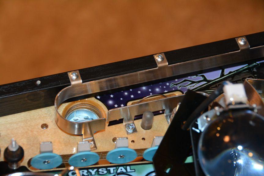
2 Remove the two ¼ screws that attach to the ball trough and ball retainer Loosen, but do not remove four Phillips screws under the playfield that attach to the inner black rail. Remove fully the screw at the farthest left circled in the pic below. This will allow the Cliffy to slide around and in place. If you do not remove this screw, the Cliffy will hit the screw and will not go through.

3 Lift up slightly on the inner black rail you just loosened and then slide the Cliffy protector under it and then into place. Reinstall screws to ball trough and retainer and then replace screw under PF and tighten the others as well. Congratulations, this one is now done and should like the pic below 2. Wizard Protector. Begin by removing the four 11/32 nuts that hold the plastic on. You will notice that one of them is under a clear plastic protector, just push the protector aside to get to that nut. You do not have to remove the plastic protector to get to the nut.


4 Cut the wire tie wrapping the spotlight cord and remove the screw and then post as in the pic below. Lay the Wizard to the side and then remove the plastic.
.")
 As you did with the protector for the shooter lane, loosen the rail screws from underneath the PF. The Cliffy must slide under this rail.")
5 Next remove the rubber and then two posts. Finally, remove the two screws that hold the scoop down. Use the included alcohol pad to wipe the area the where the Cliffy will be installed. Remove the adhesive, place in position and then press down. Reverse process to re- install everything you removed. 3. Crystal Ball VUK. Begin by removing the VUK rail (11/32 nuts in red). Be careful as the crystal ball is only held in place by one nut and will fall off once removed. Lay it to the side. Next remove the screws for the plastic (in blue) As you did with the protector for the shooter lane, loosen the rail screws from underneath the PF. The Cliffy must slide under this rail. Remove the two posts (in green) Remove rail protector (screws in yellow) Wipe area with included alcohol swab. Remove paper from adhesive and install protector. Reverse process for reinstallation.


6

7


8 4. Castle VUK. Warning, this was one of the hardest ones to install. Remove two 11/32 nuts to castle VUK (in red)and then remove castle VUK wire ramp Remove two Phillips screws (blue) to remove castle wall
.")

9 Remove two screws on Munchkin ramp (in green), followed by the spacer/stand- off (also in green). Hint: you will have to lift up on the rear of the ramp with good force to unscrew and remove that spacer Remove three 11/32 holding plastic down (in yellow). Note: one of the screws is behind the castle wall. There is a clear plastic protector above the plastic that may either be flexed to get to these nuts or removed. If you remove it, be warned that putting the rubber nubs back through the plastic protector to reinstall is not the easiest thing to do Remove 11/32 nuts from witch and then remove metal plate and plastic witch window/protector (in pink). It simple slides right up and off. Be careful to weave it around her hat. Next pry up the plastic and remove it. This will take some effort as it is on there snug. Work all the way around at each mount, do not pull too hard in one spot or you will break the plastic. Once it is off the posts, pull it towards the backbox and slide it out. Lift slightly as you pull it out to prevent the posts from scratching the plastic. Remove the two screws for the scoop (in blue)

 Use alcohol swap")


10 Remove the ¼ screws for each of the left and right metal guides (red) Use alcohol swap on area for protector, remove paper from adhesive, install protector, and reverse to reinstall.
 of the WOZ manual. There are a couple of clarifications.")

11 5. Munchkin Land Mini- PF. This was actually not that difficult with the exception of actually maneuvering the playfield out and over the upper flipper. Remove mini- pf as indicated in section E- 2 (page E- 4) of the WOZ manual. There are a couple of clarifications. In step 1 it says to remove the 4 pin (vio/yel/blk/red) from the larger hole. My 4 pin connector was (vio/blk/red/blk). This confused me for some time because the colors did not match up. Additionally, you will have to cut about 4 wire ties to remove the data connector from step 3. o Per step 1 of the manual - 4 pin connectors shown in pic below (red), 2 pin connector shown below (in blue) o Per step 2, J4 and J5 circled (in green) o Per step 3, data cable (in yellow)


12


13

14 It s OK to pull the ramp outward slightly, while lifting the mini- pf at an angle to get it out. If it feels stuck, make sure it is not caught on the flipper bat. Once the mini- pf is out, place on a soft towel and use one of the screws you removed in step 5 of the PF removal to hold the Cliffy protector in place. Pre- drill using a small drill bit making sure you put a piece of tape on the bit to gauge depth so you don t drill all the way through the PF. Also, be sure to push the protector tight against the playfield so you drill the holes in the correct locations. Once you have predrilled all holes, screw the protector into the mini- pf using the supplied screws and then reinstall being careful to put the wires back in the holes they came out of. Additionally, make sure that the light board plug you removed in step 9 is reinstalled. It should look like this before you reinstall it.

15 6-10. Rollover and magnet protectors. These were of course the easiest so I left them for last. They are pretty obvious. Use alcohol swab on area, remove adhesive paper, and stick in place. That said, a few tips. o If you use two collapsible magnetic pick ups, it allows you to place it much more precisely. This is particularly true of the monkey magnetic, which is very hard to reach to get it lined up well. Using the magnetic pick ups worked well. o Push down hard and rub your finger around them to ensure they are down. o You will also need to make sure to place them precisely over the opening or they could interfere with the rollovers. o Finally, you will likely need to adjust the rollover switches to compensate for the protector. I have not yet done that so it is not included in this tutorial. More pics of final installation below:


16


17

18
Installing Cliffy's AFM mothership protectors
 Installing Cliffy's AFM mothership protectors These instructions tell you what needs to be removed and done to install Cliffy's two new AFM protectors. The front edge protector for the moving target bank
PRINTER REPAIR ARTICLE HP LJ 4345/M4345 Swing Plate Replacement
 a1 output bin a2 DUPLEXER a4 FORMATTER COVER a5 FORMATTER a3 fuser entr. guide PRINTER REPAIR ARTICLE HP LJ 4345/M4345 Swing Plate Replacement Grinding noise near the fuser means it is time to replace
Bram Stoker's Dracula Shop Out Guide
 Bram Stoker's Dracula Shop Out Guide By Lou Perazzoli, lou.perazzoli@removeverizon.net Date: March 11, 2002. The other guides inspired this guide and served as a model. Read the Indiana Jones Guide by
IMPORTANT: WILL NOT FIT COUNTRYMAN MODELS
 Part #1410-0102-07 2 3 1 IMPORTANT: WILL NOT FIT COUNTRYMAN MODELS Apply masking tape around the bottom grille opening and across the bottom of the upper facto ry grille.. Open the hood and remove the
Motorola E815 / E816 Disassembly / Assembly Guide. Ver. 1.1 By Chubbs_WA
 Motorola E815 / E816 Disassembly / Assembly Guide Ver. 1.1 By Chubbs_WA April 10, 2007 Table of Contents Disassembly Tools needed 3 Disassembly for dummies 4 Just a note 5 Disassembly of keypad housing
Installing Your New Creature From The Black Lagoon Tail Light DMD Panel MOD
 Installing Your New Creature From The Black Lagoon Tail Light DMD Panel MOD A few things before we start: The wooden speaker panel provided in this MOD was manufactured using a Precision CNC machine and
Bushwacker Jeep Flat Style Fender Flares Front Pair
 Bushwacker Jeep Flat Style Fender Flares Front Pair Note: These instructions involve cutting parts of your vehicle. Please read all instructions prior to starting. Installation Time: 3-4 Hours Tools Required:
Bushwacker Jeep Flat Style Fender Flares Rear Pair (JK Wrangler 2dr)
") Bushwacker Jeep Flat Style Fender Flares Rear Pair (JK Wrangler 2dr) Note: These instructions involve cutting parts of your vehicle. Please read all instructions prior to starting. Installation Time: 3-4
Bushwacker Jeep Flat Style Fender Flares Rear Pair (JK Wrangler 2dr) Note: These instructions involve cutting parts of your vehicle. Please read all instructions prior to starting. Installation Time: 3-4
Volvo 240/260 New Face Overlay Installation Models By Dave Barton
 Volvo 240/260 New Face Overlay Installation 1975-80 Models By Dave Barton These custom faces are the product of years of research and experimentation. They are printed with a special printer using waterproof
C70 Window Roller Repair Taken from: Heres the problem:
 C70 Window Roller Repair Taken from: http://www.volvospeed.com/vs_forum/topic/115086-how-to-c70-window-rollers-permanent-fix/ Heres the problem: This happened to two separate window assemblys on my c70
Custom Front Panel Upgrade Instructions
 Custom Front Panel Upgrade Instructions Here are the directions for upgrading your SP-II to an SP-IIB, with a custom blackanodized front panel and engraved lettering. There are only forty SP-IIB s in existence
LED Cup Holder Lights Installation Guide
 LED Cup Holder Lights Installation Guide (20112015 Kia Optima) Thanks for purchasing this LED Cup Holder Light Kit! If you have any questions or feedback please email us direct at Sales@K5OptimaStore.com
Hatchback Wing Riser Kit
 Hatchback Wing Riser Kit 2015-06-11 Thank you for purchasing this PERRIN product for your car! Installation of this product should only be performed by persons experienced with installation of aftermarket
THIS KIT INCLUDES: 8 M8-1.25X40MM BOLTS WITH WASHERS 8 M8-1.25X30MM BOLTS WITH WASHERS RIGHT AND LEFT HINGE
 Sal es@lambodoorscanada. com 2407A Kal adarave,ottawa,on K1V 8B9 THIS KIT INCLUDES: 8 M8-1.25X40MM BOLTS WITH WASHERS 8 M8-1.25X30MM BOLTS WITH WASHERS RIGHT AND LEFT HINGE 2 SHOCKS 565 PSI 2 SHOULDER
Bend-Tech Dragon Assembly Manual
 p.1 Bend-Tech Dragon Assembly Manual IMPORTANT: Please read before unpacking. Place shipping container in a wide open area where you will have room to work and assemble this product. Shipping The Dragon
CORVETTE CORVETTE REV: Made in USA U.S. PATENT #6,808,223; #6,845,547; #7,140,075; #7,059,655 and other patents pending.
 CORVETTE 2005-2006 CORVETTE 2005-2007 REV: 7-2-07 Made in USA U.S. PATENT #6,808,223; #6,845,547; #7,140,075; #7,059,655 and other patents pending. Page 1 of 12 CORVETTE C6 2005-2007 THIS KIT INCLUDES:
1/4 Rubber Spacer, 26 pcs. M5-.8 Machine Screw, 26 pcs 13. Female Wire Connector, 4 pcs
 97-06 Jeep Wrangler TJ Set Part #10920-07 Rev-3 12-15-08 A) B) C) D) E) F) G) STEP 1 - PRIOR TO INSTALLATION Bushwacker only approves installing the fl ares according to these written instructions with
INSTALLATION. Preparation:
 INSTALLATION Preparation: Average Time Required: 2 to 3 hours Place a blanket down in the area which you will be working in. This will prevent scratches on the rear fascia / valance. Remove your License
ASHFORD TABLE LOOM - EIGHT SHAFT 410/610/800mm 16/24/32in
 INSTRUCTIONS ASHFORD TABLE LOOM - EIGHT SHAFT 410/610/800mm 16/4/3in ESTL1110016V1 Ashford Handicrafts Limited Factory and Showroom: 415 West Street PO Box 474, Ashburton 7700 New Zealand Telephone 64
TASK: Replace Control Mechanism/Drive End for G71 Supervue/Everglide Vertical headrail
 1. Locate the clear plastic louver stems where louvers are attached. 2. Rotate louvers open. Slide a hard plastic card between the louver and the long side of the louver stem. Push the card and louver
Written By: Andrew Optimus Goldberg
 Replace the screen your GSM/AT&T iphone 4. Written By: Andrew Optimus Goldberg ifixit CC BY-NC-SA www.ifixit.com Page 1 of 25 INTRODUCTION [video: http://www.youtube.com/watch?v=obpfpfx5abw] Use this guide
Chevy Tahoe Utility Vehicle
 Chevy Tahoe Utility Vehicle 1 TOOLS NEEDED 5/8 Step Drill Bit Hand Drill or Cordless Drill Measuring Tape or Ruler Grease Pencil (White or Black) Small Tie Wraps Silicone Adhesive Sealant Phillips Screw
BABY WOLF LOOM. Assembly Instructions for Knocked-Down Looms
 BABY WOLF LOOM Assembly Instructions for Knocked-Down Looms BEFORE YOU BEGIN Please read through the directions before beginning to assemble your loom. Unpack the loom parts carefully. Do not throw away
BX2173 Installation Instructions Ford Focus (including the 2.3L engine) 2003 Ford Focus SVT
 2003 Ford Focus SVT") BX2173 Installation Instructions 2000-04 Ford Focus (including the 2.3L engine) 2003 Ford Focus SVT Serial No. The front fascia, coolant line bracket and anti-pollution devices are removed for baseplate
BX2173 Installation Instructions 2000-04 Ford Focus (including the 2.3L engine) 2003 Ford Focus SVT Serial No. The front fascia, coolant line bracket and anti-pollution devices are removed for baseplate
* Drill and 3/32" drill bit: for drilling holes in the factory plastic upper for the screws to secure the brackets (factory upper installation only)
") * Two slider windows (four sliders windows for the 4-door kit) * Four brackets to secure the windows to the upper door frames (8 brackets for the 4-door kit) * Weatherstrip to seal the windows to the half
* Two slider windows (four sliders windows for the 4-door kit) * Four brackets to secure the windows to the upper door frames (8 brackets for the 4-door kit) * Weatherstrip to seal the windows to the half
JK JEEP MIDWIDTH FRONT BUMPER
 SIGNATURE SERIES JK JEEP MIDWIDTH FRONT BUMPER INSTALLATION INSTRUCTIONS **PLEASE READ THROUGH THE INSTRUCTIONS BEFORE BEGINNING ANY PART OF THE INSTALLATION PROCESS** 1. Begin the installation of your
7878 K940. Checkpoint Antenna. Kit Instructions. Issue B
 7878 K940 Checkpoint Antenna Kit Instructions Issue B Revision Record Issue Date Remarks A July 7, 2009 First issue B Nov2013 Revised the Checkpoint installation procedures for 7878 and 7874 scanners Added
INTERCOOLER UPGRADE INSTALLATION INSTRUCTIONS PART NUMBER D APPLICATION: F87 M2
 INTERCOOLER UPGRADE INSTALLATION INSTRUCTIONS PART NUMBER D330-0026 APPLICATION: 2016-17 F87 M2 Congratulations for being selective enough to use a Dinan Intercooler Upgrade Kit. We have spent many hours
Dragon A400 Assembly Manual
 1 Dragon A400 Assembly Manual Crate Size: 120 L x 65 W x 80 H Machine Size (After Assembly): 372 L x 30 W x 72 H The Dragon A400 will arrive in its crate and will need to be opened with a minimum of two
Assembly Instructions 10 X 10 Aluminum Frame Building
 Assembly Instructions 10 X 10 Aluminum Frame Building 27 97 9 8 47 36 74 52 10 10 X 10 Square Building W/ Dome Includes: The Steel Entry Door with a Dead Bolt Lock assembly and Aluminum Door Frame. Metal
Mini Cooper Lock Actuator
 2001-2006 Mini Cooper Lock Actuator Replacement This guide is on how to remove the lock actuator from the cars door. Written By: Jem ifixit CC BY-NC-SA www.ifixit.com Page 1 of 13 INTRODUCTION In order
ELECRAFT Application Note
 ELECRAFT Application Note Front Panel Microphone Circuit Modification Revision A, November 12, 2008 Copyright 2008, Elecraft, Inc., All Rights Reserved Background Some K3 owners have noted distorted transmit
OTHER TOOLS MAY BE NEEDED DEPENDING ON YOUR VEHICLE.
 THIS KIT INCLUDES: 16 M8-1.25X40MM BOLTS WITH WASHERS 2 SHOCKS 720 PSI RIGHT AND LEFT HINGE ASSEMBLY 2 SHOULDER BOLTS 2 PINS TOOLS REQUIRED FOR INSTALLATION: AIR RACHET, GRINDER AND CUTTER. 10MM, 11MM,
AUTOMATIC ADVANCE MANUAL
 AUTOMATIC ADVANCE MANUAL AVL Looms, Inc. 3851 Morrow Lane, Suite #9 Chico, CA 95928-8305 530 893-4915 530 893-1372 fax # info@avlusa.com www.avlusa.com Copyright 2009 TABLE OF CONTENTS Page # I. Parts.........................
ROMAN AND. Roller Lift System Continuous Cord Loop GETTING STARTED BRACKET INFORMATION INSIDE MOUNT. A few simple tools are required:
 ROMAN AND WOVEN WOOD SHADES Roller Lift System Continuous Cord Loop GETTING STARTED BRACKET INFORMATION A few simple tools are required: The brackets you received with your product are REQUIRED for proper
Removing and Replacing the Y-truck
 Service Documentation Removing and Replacing the Y-truck To remove and replace the Y-truck you will need the following tools: 4mm Allen wrench 12mm stamped flat wrench #2 Phillips screwdriver (magnetic
HQ Precision-Glide Track Upgrade 2 Extension Kit for HQ Studio Frame Part# QF09750
 HQ Precision-Glide Track Upgrade 2 Extension Kit for HQ Studio Frame Part# QF09750 Important Note: Upgrading the track system on the HQ Studio Frame requires the use of this 2 Extension Kit (Part #QF09750),
iphone 6 Chargeport REPAIR GUIDE Version Edition
 iphone 6 Chargeport REPAIR GUIDE Version 1 2016 Edition IPHONE 6 CHARGEPORT REPAIR GUIDE LCD AND DIGITIZER REPLACEMENT RiAna Soto Repair Training Specialist rsoto@cellairis.com FOR EVERY REPAIR MAKE SURE
INSTALL/REMOVAL INSTRUCTIONS: WINDOW REGULATOR
 REMOVAL/INSTALL OF WINDOW REGULATOR (741-584) Ford Focus 2000-2007 General Tech Tips: Use painter s tape rather than duct tape to secure window. It will not damage paint or leave sticky residue. A plastic
AUDI A8 D3 REPLACING THE OUTSIDE DRIVER DOOR HANDLE
 AUDI A8 D3 REPLACING THE OUTSIDE DRIVER DOOR HANDLE The keyless entry system in the D3 is a great feature. If you have the car key fob in your pocket, putting your hand under the door handle will unlock
SuperTrack Parts List
 SuperTrack Parts List [indicates number for 6 lane tracks] SuperTrack Installation Instructions www.supertimer.com 1-800-654-2088 1 Track Instruction Manual (this booklet) 2 Start sections [3] Start Gate
OPERATING INSTRUCTIONS. for the double plate extension. Secabo Slide for TC5 and TC7
 OPERATING INSTRUCTIONS for the double plate extension Secabo Slide for TC5 and TC7 Congratulations on purchasing a Secabo product! Please read these operating instructions carefully before using the product.
Astro-Physics Inc. 400QMD Lubrication/Maintenance Guide
 Astro-Physics Inc. 400QMD Lubrication/Maintenance Guide The following guidelines should be followed to lubricate the three main parts of the 400QMD mount. The QMD stands for Quartz Micro-Drive controller.
Tools needed: Phillips screwdriver, flat blade screwdriver, rubber cement, clean hands.
 Installing the New Face for the Volvo 740 Turbo Vacuum/Boost Gauge INTRODUCTION: These instructions will guide you through the installation of this new face for your existing vacuum/boost gauge. It is
Written By: Walter Galan
 ipad 3 Wi-Fi Dock Connector Replacement Replace the dock connector in your ipad 3 Wi-Fi. Written By: Walter Galan ifixit CC BY-NC-SA www.ifixit.com Page 1 of 29 INTRODUCTION Use this guide to replace the
KN-8828B Upgrade Directions
 KN-8828B Upgrade Directions This document outlines the steps to take to update earlier Hottop Bean Roasters to the KN-8828B 2007 by Chang Yue and Hottop USA - All Rights Reserved No part of this document
METAL BLINDS. Deluxe GETTING STARTED OPTIONAL HARDWARE. A few simple tools are required: STANDARD HARDWARE
 METAL BLINDS Deluxe GETTING STARTED OPTIONAL HARDWARE A few simple tools are required: Steel Tape Measure Pencil Level Hold Down Brackets with Screws Extension Bracket Power Drill and Drill Bits Flathead
Written By: Evan Noronha
 Replace the logic board in an ipad Air LTE. Written By: Evan Noronha ifixit CC BY-NC-SA www.ifixit.com Page 1 of 50 INTRODUCTION Follow the steps in this guide to replace the logic board in an ipad Air
The Useless Machine. DIY Soldering Edition. Instruction Guide v0004
 The Useless Machine DIY Soldering Edition Instruction Guide v0004 TM For the best outcome, follow each step in order. We recommend reading this guide entirely before you get started. Tools required: Soldering
WOLF PUP LOOM TM & WOLF PUP LT LOOM TM
 WOLF PUP LOOM TM & WOLF PUP LT LOOM TM Assembly Instructions FL3000 FL3006 FL3009 WOLF PUP WOLF PUP LT Find out more at schachtspindle.com Schacht Spindle Company 6101 Ben Place Boulder, CO 80301 p. 303.442.3212
re3d Assembling Gigabot: "Flatpack"
 re3d Assembling Gigabot: "Flatpack" Your Gigabot was assembled, calibrated, tested, and taken apart for shipping purposes. All you need to do is reassemble it, and you're ready to go! Written By: Chris
Triplex Instructions for Packing and Unpacking
 2-8-8-2 Triplex Instructions for Packing and Unpacking It is recommended that you review all these instructions before removing the engine or tender from the poly foam container. www.mthtrains.com Table
The build should take around 2 to 3 hours. However, by leaving yourself more time you can go at a relaxed pace and be sure not to miss anything.
 Before We Start Before we jump into building your Picade, make sure you have everything to hand. I know you're eager to jump right into the construction, but we need to get set up properly first! 1. Prepare
Jeep. Flat Style Fender Flares Set of 4. Included in Hardware Kit: STEP 1 PRIOR TO INSTALLATION. Set Part # Rev-3 1/11/2016
 STEP 1 PRIOR TO INSTALLATION A) Bushwacker only approves installing the fl ares according to these written instructions with the hardware provided. WARNING: Failure to install according to these instructions
Iphone 5 Glass/Lcd REPAIR GUIDE. Version Edition
 Iphone 5 Glass/Lcd REPAIR GUIDE Version 1 2016 Edition IPhone 5 Glass/LCd REPAIR GUIDE RiAna Soto Repair Training Specialist rsoto@cellairis.com FOR EVERY REPAIR MAKE SURE TO COMPLETE, INITIAL, AND HAVE
Bed Extension Kit 16 Instructions
 The premier source of tooling, parts, and accessories for bench top machinists. Bed Extension Kit 16 Instructions This kit converts a 7 10, 7 12, and 7 14 mini lathe manufactured by SIEG (including those
Rockwell Automation PowerFlex 755 Disassembly
 Rockwell Automation PowerFlex 755 Disassembly Disassembling a 1HP Rockwell Automation PowerFlex 755 VFD. Written By: Alex Nolan ifixit CC BY-NC-SA www.ifixit.com Page 1 of 12 INTRODUCTION This guide outlines
Flat Style Fender Flares Front Pair. Jeep. Included in Hardware Kit:
 Jeep Flat Style Fender Flares Front Pair STEP 1 PRIOR TO INSTALLATION A) Bushwacker only approves installing the fl ares according to these written instructions with the hardware provided. WARNING: Failure
WARNING. BX Ford Explorer With Adaptive Cruise Control & Eco Boost Installation Instructions
 Please read BOTH these and the General Instructions before attempting to install or operate this equipment. 1. Blue Ox towing products and accessories are intended to be installed by Blue Ox Dealers who
RAIL 4 PERIMETER RP4D RECESSED T-BAR LED TELESCOPIC, INTEGRAL DRIVER
 INSTALLATION INSTRUCTIONS RAIL 4 PERIMETER RP4D RECESSED T-BAR LED TELESCOPIC, INTEGRAL DRIVER NOTE: The following instructions provide general guidelines for product installation. For additional information
The Queen Quilter Professional Quilters Kit Frame
 The Queen Quilter Professional Quilters Kit Frame Assembly Instructions Table of Contents: Before you begin......................... Pg. 2 Wood parts............................. Pg. 3 Hardware..............................
This instruction manual is an in-depth look and explanation of how to assemble and install the Murphy Bed properly and efficiently.
 This instruction manual is an in-depth look and explanation of how to assemble and install the Murphy Bed properly and efficiently. Don t be put off by the size of the instruction manual as the large diagrams
Please read BOTH these Installation Instructions and the General Instructions before attempting to install or operate this equipment.
 Please read BOTH these and the General Instructions before attempting to install or operate this equipment. 1. Blue Ox towing products and accessories are intended to be installed by Blue Ox Dealers who
ipad 3 4G Home Button Control Board Replacement
 ipad 3 4G Home Button Control Board Replacement Replace the home button control board in your ipad 3. Written By: Brett Hartt ifixit CC BY-NC-SA www.ifixit.com Page 1 of 28 INTRODUCTION This guide will
ABM International, Inc. Navigator Assembly Manual
 ABM International, Inc. 1 1.0: Parts List Tablet (Qty. 1) Tablet mount (Qty. 1) NOTE: Mount may appear and operate different then image below Control Box (Qty. 1) Motor Power Supply (Qty. 1) 2 X-axis motor
Toyota Tacoma Interior Light Upgrade
 Toyota Tacoma 2011- Interior Light Upgrade Part Number 00016-00095 Accesory Code: IL2 Conflicts Kit Contents Item # Quantity Reqd. Description 1 1 Y Adapter 2 1 Wire harness 3 1 Hardware Kit 4 2 White
compile system INSTALLATION GUIDE Updated January 2019
 INSTALLATION GUIDE Updated January 09 compile system Table of Contents Panels 0 Quick Connect Clips 0 Lock Clips 0 Panel Trims 0 Privacy Glass 0 Post Base Covers 04 Electrical 04 Power Distribution Harness
Q-Zone Hoop-Frame. Assembly Instructions. Copyright July 11, 2018 Grace Company (Reproduction Prohibited) Version 1.8
 Version 1.8") Q-Zone Hoop-Frame Assembly Instructions Copyright July 11, 2018 Grace Company (Reproduction Prohibited) Version 1.8 Table of Contents Table of Contents... i Warranty... ii Parts List Box 1...iii Box 2...
Q-Zone Hoop-Frame Assembly Instructions Copyright July 11, 2018 Grace Company (Reproduction Prohibited) Version 1.8 Table of Contents Table of Contents... i Warranty... ii Parts List Box 1...iii Box 2...
Installation instructions, accessories. Rails. Volvo Car Corporation Gothenburg, Sweden. Instruction No Version Part. No
 Instruction No Version Part. No. 8685942 1.0 Rails J8401014 Page 1 / 9 Equipment A0000162 A0000161 J8401006 Page 2 / 9 INTRODUCTION Read through all of the instructions before starting installation. Notifications
Replacing a Wheel on the Pinch Wheel assembly
 14140 NE 200th St - Woodinville, WA. 98072 - PH: (425) 398-8282 - Fax: (425) 398-8383 Replacing a Wheel on the Pinch Wheel assembly Determine which pinch wheel assembly your plotter or cutter has. See
ipad 3 4G Home Button Assembly Replacement
 ipad 3 4G Home Button Assembly Replacement Replace the home button assembly in your ipad 3 4G. Written By: Brett Hartt ifixit CC BY-NC-SA www.ifixit.com Page 1 of 29 INTRODUCTION Use this guide to replace
Written By: Walter Galan
 Replace the Logic Board in your ipad 4 Wi-Fi. Written By: Walter Galan ifixit CC BY-NC-SA www.ifixit.com Page 1 of 32 INTRODUCTION Use this guide to replace the logic board. TOOLS: iopener (1) Phillips
Custom Grille Insert
 1 of 8 Thank you for your purchase of DBCustomz 2016+ Toyota Tacoma! This product was carefully crafted to ensure a perfect fit with your vehicle. The instructions below are provided to allow for an easier
V-MOTION LITE USER GUIDE. Rat Rig All rights reserved.
 V-MOTION LITE USER GUIDE Rat Rig 2017. All rights reserved. PACKAGE CONTENTS 1 1x V-Motion Motor 2 1x Belt 3 1x 3mm Hex Key 4 1x AA Battery Pack (for 8x AA batteries)* 5 1x V-Motion Controller 6 2x Knob
Installation, Usage and Maintenance Guide
 Installation, Usage and Maintenance Guide October 2012 WARNING Read this document before installing or using Johnny Mnemonic Topper Mod by Pinballtoppers Improper installation, improper use, may cause
Installation and Operating Instructions
 INSTRUCTIONS Installation and Operating Instructions In these installation instructions is described the replacement of the elevating support with gas springs. This conversion kit applies to all California
Written By: Walter Galan
 ipad 4 CDMA SIM Board Replacement Replace the SIM Board in your ipad 4 CDMA. Written By: Walter Galan ifixit CC BY-NC-SA www.ifixit.com Page 1 of 33 INTRODUCTION Use this guide to replace the SIM Board.
ASSEMBLY INSTRUCTIONS FOR SL500A AND SL500AL
 ASSEMBLY INSTRUCTIONS FOR SL500A AND SL500AL January 2013 The SL500A is a square upright glass cabinet with a single hinged lockable door. It has five adjustable shelves plus the base. It also has an optional
Kai Installation Instructions
 Kai Installation Instructions Before Beginning Installation Read through the entire instruction thoroughly A minimum of 2 people are required for this assembly These instructions reflect typical assemblies;
LOCK ASSEMBLY INSTRUCTIONS
 LOCK ASSEMBLY INSTRUCTIONS Use the drawing below as a key to determine which lock assembly instruction to follow. There are three different types of locks used, and the instructions for each are on the
/ Rudder Installation Guide
 / Rudder Installation Guide Parts List Part # Part Description Qty Part # Part Description Qty 1030 Plastic Bead 1 1195 Rope; 1/8" Black Nylon 1 @ 9 1044 1/4-20 x 5/8" Pan Head Bolt 2 1353 Sliding Track
STELLA AUTO SIDECAR INSTALL INSTRUCTIONS
 STELLA AUTO SIDECAR INSTALL INSTRUCTIONS Open crate and inspect sidecar Remove cardboard box from inside the sidecar Remove all hardware holding the sidecar to the crate Remove sidecar from crate Remove
kitsch-bent > el_dmg ver. 1 3/25/2012 kitsch-bent.com
 kitsch-bent > el_dmg ver. 1 3/25/2012 kitsch-bent.com before we begin... tips steps 1-6 may be completed before your kit arrives in the mail. this let's you install the kit much quicker when it arrives
Tools Needed Hardware Provided (per shade) Hardware Needed
 Hardware Needed") Baby Grande or Grande Motorized (XQ5 Premium) Shade with Cables and Housing Installation Instructions Tools Needed Hardware Provided (per shade) Hardware Needed Drill 3/8 Metal Drill Bit Measuring Tape
Baby Grande or Grande Motorized (XQ5 Premium) Shade with Cables and Housing Installation Instructions Tools Needed Hardware Provided (per shade) Hardware Needed Drill 3/8 Metal Drill Bit Measuring Tape
Door window. Front door window, assembly overview
 64-50 Door window Front door window, assembly overview 1 - Window channel Pushed onto flange 2 - Door window Removing Page 64-52 Adjusting Page 64-53 3 - Door 4 - Outer window channel Pushed onto flange
Written By: Brett Hartt
 ipad 3 4G LCD Replacement Removing the LCD Written By: Brett Hartt ifixit CC BY-NC-SA www.ifixit.com Page 1 of 25 INTRODUCTION The third generation ipad loses a lot of luster when its gorgeous retina display
INSTALLATION INSTRUCTIONS FOR SL-LB MANUAL LIFT BARRIER GATE ARMS
 INSTALLATION INSTRUCTIONS FOR SL-LB MANUAL LIFT BARRIER GATE ARMS Questions? Call 520-780-9751 or visit our website at: www.barriergatearm.com YOUR SL-LB MANUAL LIFT BARRIER GATE ARM WILL ARRIVE WITH WEIGHT
IMPORTANT: PLEASE RETAIN THIS INSTRUCTION MANUAL FOR FUTURE REFERENCE
 IMPORTANT: PLEASE RETAIN THIS INSTRUCTION MANUAL FOR FUTURE REFERENCE 005-07 Cadillac STS Classic 3D Z, Classic Dual Weave, Classic Mesh & Classic Black Mesh Grilles B 7 HR 3 STS Classic 3D Z Grille Part
Written By: Walter Galan
 Replace the logic board in your ipad 3 Wi-Fi. Written By: Walter Galan ifixit CC BY-NC-SA www.ifixit.com Page 1 of 29 INTRODUCTION Use this guide to replace the logic board. TOOLS: iopener (1) Phillips
INSTALLATION INSTRUCTIONS
 INSTALLATION INSTRUCTIONS Thank You, for your recent purchase with TrimLine Windows, Inc. This is a quality product and deserves a quality installation. Please follow the attached instructions for a quick
Signal Mirror Installation Instructions Honda Odyssey
 Signal Mirror Installation Instructions 2005-2009 Honda Odyssey THE safety accessory of the 21st Century. P/N 210-0122-0 Rev. A4 (6/9/09), BTV 2006 Muth Company, LLC PROFESSIONAL INSTALLATION RECOMMENDED
001-Component-build. Build the following Contraptor components before assembly:
 001-Component-build Build the following Contraptor components before assembly: http://www.contraptor.org/make-linear-rail-v2#assembly http://www.contraptor.org/make-linear-bearings-v2#assembly http://www.contraptor.org/make-sliding-elements#assembly
Assembly Instructions 10 X 10 Aluminum Roof Support
 Assembly Instructions 10 X 10 Aluminum Roof Support Aluminum Roof Support Bolt Package 16-5/16 X 2 ¼ SS Bolt 24-5/16 X 1 SS Bolt 40-5/16 SS Nylon Lock Nuts 16-5/16 SS Flat Washers 28-4 ½ Wood Screws 36-1
Adjustable Hammered Dulcimer Stand
 Adjustable Hammered Dulcimer Stand Musicmaker s Kits (Hwy 36 behind Joseph s Restaurant) P.O. Box 2117 Stillwater MN 55082 651 439 9120 www.harpkit.com PARTS LIST: 1 Set of Assembly Instructions A. 2 front
Repairing iphone 4 LCD Backlight Dim spot issue
 Repairing iphone 4 LCD Backlight Dim spot issue found a way to fix a liquid damaged iphone screen back light issue Written By: Pranav Singh ifixit CC BY-NC-SA www.ifixit.com Page 1 of 26 INTRODUCTION found
EmagiKit. Privacy Pod Plus. Quiet. Easy. Affordable. INSTRUCTIONS ASSEMBLY
 EmagiKit Privacy Pod Plus Quiet. Easy. Affordable. INSTRUCTIONS ASSEMBLY DIMENSIONS AND COMPONENTS 47 47 Ceiling Unit 2-B 2-L 2-R Glass Door Corner Trim Door Handle 90 Adjustable Height Work Surface 1-B
WARNING!! DO NOT LIFT DOORS UP WHEN THE HOOD IS OPEN. THE DOORS WILL HIT THE HOOD!
 WARNING!! DO NOT LIFT DOORS UP WHEN THE HOOD IS OPEN. THE DOORS WILL HIT THE HOOD! THIS KIT INCLUDES: 4 M8-1.25X30MM BOLTS WITH WASHERS 12 M8-1.25X40MM BOLTS WITH WASHERS 2 SHOULDER BOLTS WITH RIGHT AND
Product must be installed as shown using the screws and brackets provided. Use of incorrect hardware could result in damage to the product.
 General Notes These installation instructions are intended to be comprehensive for a typical Keyeira/Presto configuration. Your configuration may differ. If you have questions contact Geiger Customer Service
Instructions to fit Emulator in place of floppy drive M.D.R.
 Instructions to fit Emulator in place of floppy drive M.D.R. Before starting, read through all the following instructions, and then when you do begin, read each number section before attempting that particular
Aircraft assembly and disassembly
 Following instructions are related to ATEC 321(322) FAETA with wingtanks, but in general the basic methodics (besides several few differencies) is applicable also to other ATEC models. Aircraft assembly