TECHNICAL DESIGN CATALOG
|
|
|
- Clare Dorsey
- 6 years ago
- Views:
Transcription

1 TECHNICAL DESIGN CATALOG

2 Disclaimer: The Steeler Technical Design Catalog is a collection of typical designs for steel framing and connections to help guide with your design process. The Calalog should only be used as a guide, as these are typical designs and have not been tested in all situations or scenarios. You should consult with your architecture and engineering firms during the design process before applying any of the typical designs or ideas. Local building codes may require certain designs and may have special considerations that you may not be familiar with. ICBO ES REPORT #4389P (206) (206) FAX (800) Toll Free Martin Luther King Jr. Way South Seattle, WA marketing@steeler.com
3 Table of Contents General Section: G1 Schematic of Typical Steel-Framed House G2 C-shape Configuration G3 Track Configuration G4 Joist Web Holes G5 Stud Web Holes G6 Joist Web Hole Patch G7 Stud Web Hole Patch 1 G8 In-Line Framing Detail G9 Web Stiffener Detail 1 G10 Web Stiffener Detail 2 G11 Web Stiffener Detail 3 G12 Track Splice Detail G13 Screw Attachment Detail Floor Section: F1 F2 F3 F4 F5 F6 F7 F8 F9 F10 F11 F12 F13 F14 F15 F16 F17 F18 F19 F20 F21 F22 Floor Framing Floor to Foundation Connection Floor to Wood Sill Connection Floor to Load Bearing Wall Connection Floor Bearing on I-Beam Connection Lapped Joists Continuous Joist Floors to I-Beam Side Connection Joists Supported by Shallow I-Beam Joists Supported by Deep I-Beam Floor Joists at Interior Bearing Wall Joists Bearing on Foundation at Opening Floor to CMU Wall Side Connection Web Stiffener at Load Bearing Wall Alternate Pony Wall Detail Cantilevered Joist to Foundation Connection Cantilevered Joist to Wood Sill Connection Cantilevered Joist to Bearing Wall Connection Cantilevered Joist to Wood Top Plate Connection Double Cantilevered Joists Wood Deck Balcony Beam Support with Column Rev. March 11, 2011
4 Table of Contents Floor Section (Continued): F23 F24 F25 F26 Floor Blocking Detail 1 F27 Floor Blocking Detail 2 F28 Floor Blocking Detail 3 Beam Support with Column Floor Opening Detail Floor Header and Trimmer Detail F29 Floor Blocking Detail 4 F30 Bridging Detail Load-Bearing Walls Section: W1 Schematic of Typical Wall Framing W2 Wall Framing Elevation W3 Wall to Foundation W4 Wall to Foundation W5 Wall to Foundation W6 Wall to Foundation W7 Wall to Wood Sill Connection W8 Hold-Down Connection Detail 1 W9 Hold-Down Connection Detail 2 W10 Box Beam Header W11 Box Beam Header W12 Back-to-Back Header with Jack Stud W13 Back-to-Back Header W14 L-Header Detail W15 Single L-Header Detail W16 Double L-Header Detail W17 Stud Bracing with Cold-Rolled Channel W18 Stud Bracing with Sheathing W19 Stud Bracing with Strapping and Sheathing W20 Stud Bracing with Strapping and Blocking W21 Structural Sheathing Fastening to Wall Studs W22 Shearwall and Diaphragm Details W23 Sheathed Wall with Opening W24 Single Story X-Brace Detail W25 Two Story X-Brace Detail W26 Two Story Sheathed Wall Detail W27 X-Brace Detail W28 X-Brace with Gusset Detail W29 Corner Framing Detail
5 Table of Contents Non-Load Bearing Walls: NL1 NL2 NL3 NL4 NL5 NL6 NL7 NL8 Non-Load Bearing Wall Framing Sill and Head Track Connection Detail Corner Framing Detail Slammer Stud Detail Window Opening Framing Detail Door Opening Framing Detail Non-Load Bearing Opening Non-Load Bearing Wall Parallel to Joist Roofs (Rafters/Joists): R1 R2 R3 R4 R5 R6 R7 R8 R9 R10 R11 R12 R13 R14 R15 Roof Framing Joist and Rafter Detail Roof Framing Isometric View Heel Joint Connection Detail Ridge Member Connection Detail Ridge Member with Coped Rafters Roof Eave and Soffit Detail Rafter and Joist Bridging Collar Tie at Rafter Detail Rafter Brace Connection Detail Roof Framing with Wood Tail Extension Wood Truss Bearing on Steel Wall Collector Block Detail Non-aligned Roof-Wall framing Hip Beam Miscellaneous: M1 M2 M3 M4 M5 M6 Cabinet Blocking Detail Wiring and Piping Installation Detail Stair Framing Stair Framing Stair Landing Window Sill
6
7
8
9
10
11
12
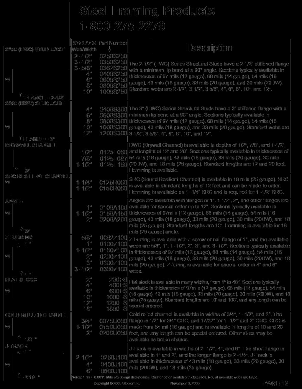
13
14
15
16
17
18
19
20
21
22
23
24
25
26
27
28
29
30
31
32
33
34
35
36
37
38
39
40
41
42
43
44
45
46
47
48
49
50
51
52
53
54
55
56
57
58
59
60
61
62
63
64
65
66
67
68
69
70
71
72
73
74
75
76
77
78
79
80
81
82
83
84
85
86
87
88
89
90
91
92
93
94
95
96
97
98
99
100
101
102
103
104
105
106
107
108
109
110
111
112
113 STEELER Hemmed Angle Eliminate finger cuts, lost time due to injuries, and workman compension claims with STEELER Hemmed Angle. Non-hemmed 25 gauge steel has extremely sharp edges that can cut your hands and fingers very easily. Hemmed angle has edges that are bent over the flanges to make a smooth edge that is less sharp and easier to handle. The hemming also stiffens the angle significantly. Hemmed angle is easier and safer to work with, thus increasing productivity. STEELER HEMMED ANGLE HEMMING NOT TO SCALE Hemmed angle is available in 25 gauge and lengths from 3" to 20' lengths. Hemmed angle is available with flanges of 1", 1-1/4", 1-1/2", 2", and 2-1/2". Both flanges must be the same size. Hemmed angle is manufactured from light gauge steel meetings the requirements of ASTM A653-02a or equal. Typical uses for hemmed angle include bridging, bracing, blocking, and other situations that would require light gauge angles. In addition to angles, STEELER offers hemming on most 25 gauge products such as Sound Resilient Channel, Drywall Channel (DWC / Furring Channel), Studs, Tracks, and C-H Shaftwall Studs. Steeler Part #: 0100A H 0125A H 0150A H 0200A H 0250A H Description: 1" x 1" Hemmed Angle, 25 Gauge 1 1/4" x 1 1/4" Hemmed Angle, 25 Gauge 1 1/2" x 1 1/2" Hemmed Angle, 25 Gauge 2" x 2" Hemmed Angle, 25 Gauge 2 1/2" x 2 1/2" Hemmed Angle, 25 Gauge Martin Luther King Jr. Way South, Seattle, WA FAX Steeler and Steeler, Inc. are registered trademarks of Steeler, Inc. Copyright 2003 Steeler, Inc. All Rights Reserved. Document: ST-HA April 28, 2003


114 STEELER Engineered Slide Clip Building structures move with dead, live and snow loads, wind and seismic forces, and temperature changes. STEELER has designed and engineered a slide clip that isolates the non-load wall system from the structure. The STEELER slide clip allows the structure to deflect vertically for any designed vertical deflection and its simple design saves time and money compared to other products and installation methods. Consult with your Engineering firm before using this product Martin Luther King Jr Way South, Seattle, WA FAX Steeler and Steeler, Inc. are registered trademarks of Steeler, Inc. Copyright 2003 Steeler, Inc. All Rights Reserved. ST-VSC September 10, 2003
115 Custom Brake Shapes B B D C B 90 1 A 90 ANGLE B A B B F A C A J TRACK E 7 D 9 E PITCHED TRACK Z SHAPES A C A B C A ANGLE OVER B 11 D C D CUSTOM SHAPES 5 A GUTTER SHAPES F C STAIR PANS 13 C B B C B B C D 10 A 8 A 12 6 A C A HAT SECTION D HAT SECTION 2 E F D DEFLECTION TRACK B ANGLE UNDER 90 C B & C LEGS UP TO 6" DEEP A D DEEP LEG TRACK E C UP TO 6" 14 NOTE: SPECIFY LEG LENGTHS CUSTOM SHAPES STEELER INC. will provide brake shapes to you on an as needed basis. We are able to provide custom shapes for your special job requirements within reasonable lead times. At left are some shapes which are common in industry and dimensioning variables to help you with your ordering. Our shop is not limited to these shapes and it is just a matter of a request to receive information on shapes not shown. Materials a) Light gauge steel meeting the physical and galvanization requirements of A.S.T.M. A-653 or equal. b) Shape and Dimensions as requested c) Maximum Length = 32' - 0" d) Gauges available: 25, 20, 18, 16, 14, 12, 10 and up to 1/4 of an inch thick. e) Packaging = Varies on Order f) Up to 6 brakes/bends available (BS1 = 1 bend; BS6 = 6 bends) Ordering information Please be sure to provide quantity, length, thickness (gauge) and appropriate dimensional information. A drawing of the brake shape is required for all orders. Be sure to identify inside or outside measurements and to let us know of acceptable variances on angles or dimensions. Consult with your engineering firm before using this product Martin Luther King Jr. Way South - Seattle, WA (206) (206) FAX - Steeler and Steeler, Inc. are registered trademarks of Steeler, Inc. Copyright 2003 Steeler, Inc. All Rights Reserved. Document: ST-BS September 10, 2003
116 DFT (Deflection Track) Materials a) Light gauge steel meeting the physical and galvanization requirements of A.S.T.M. A-653 or equal. b) Shape and Dimensions as shown at left. c) Length = 10' - 0" d) Widths available: 3-1/2", 3-5/8", 4", 6", 8" e) Gauges available: 25, 20, 18, & 16. d) Packaging = Varies on Order W 1/2" Wafer head driller screw (STEELER P/N 34 Super Wafer Head Driller) 1-1/4 Installation 1) Walls assembled with deflection track are assembled similar to standard load bearing walls except that stud lengths are 1-3/ 8 inch shorter to allow for the deflection track's equivalent height. This 1-1/4 inch track height is able to expand and contract to allow for the ceiling deflection. Standard lower track is used in these walls. Sheathing is done as normal except that it must be held back from the top of the track. STEELER INC. is introducing an economical alternative for ceiling connections of non-load bearing walls. Our new deflection track may allow ceilings to deflect under loading without affecting the wall beneath. Performance is based upon gauge and must be determined by the Job Engineer. In many cases a slip track application may be changed to deflection track saving both material and labor at installation. 2) Walls should be framed with a 1/2" Wafer head driller screw (STEELER P/N 34Super). 3) Sheathing - Use a 1-1/8" Super Steeler drywall screw (STEELER P/N 268) to secure 1/2" drywall and a 1-1/4" Super Steeler drywall screw (STEELER P/N 368) to secure 5/8" drywall to either 25 or 20 gauge studs. Use a 1 1/4" drywall driller screw to attach to the 18 gauge studs (STEELER P/N 14). Consult with your engineering firm before using this product Martin Luther King Jr. Way South - Seattle, WA (206) (206) FAX Steeler and Steeler, Inc. are registered trademarks of Steeler, Inc. Copyright 2003 Steeler, Inc. All Rights Reserved. Document: ST-DFT March 14, 2003
117 CRC (Cold-Rolled Channel) Materials a) Light gauge steel meeting the physical and galvanization requirements of ASTM A-653 or equal. b) Shape and Dimensions shown at left. c) Length and Special lengths are available. d) Sizes - ¾, 1½, and 2. Installation a) Suspended Drywall Ceiling erection- install CRC 48 on center as the main carriers and within 6 of walls. Secure with 8 ga. or 9 ga. STEELER hanger wire (saddle tie). Spices- interlock flanges and overlap ends 12 and secure with 1 strand of 16 ga. or 2 strands of 18 ga. tie wire. STEELER, INC. provides CRC cold-rolled channel made from 16 gauge. CRC is used for furring walls and ceilings and suspended ceilings. Also used for laterally bracing in steel stud wall systems and ornamental lathing. Available in galvanized per ASTM A-653 or equal. b) Suspended Plaster Ceilingapply ¾ CRC across at right angles to 1½ CRC. Space 12 to 24 depending on type of lath. Saddle tie to 1½ carriers with tie wire. c) Walls- Refer to page 51 of our ICBO Report for bridging applications. Consult with your engineering firm before using this product Martin Luther King Jr. Way South, Seattle, WA (206) (206) FAX Document: ST-CRC March 8, 2003 Steeler and Steeler, Inc. are registered trademarks of Steeler, Inc. Copyright 2003 Steeler, Inc. All Rights Reserved.
118 12 SRC (Resilient Channel) REF: Gypsum Association ICBO, ES, Inc. Report # 1632 Materials a) Light gauge steel meeting the physical and galvanization requirements of A.S.T.M. A-653 or equal. b) Shape and Dimensions in accordance with Gypsum Association Fire Resistance and Sound Control Design Manual, page 14, as shown at left. Available flanges of 1-1/4" and Extra Wide 1-1/2". A STEELER part #300 (wood) or #368 (wood) or #31 (steel) or #34 (steel) B c) Length = 12' - 0" Custom Lengths Available. d) Packaging = Bundles of 40 (480 feet per bundle) e) Available with hemming for 1-1/4" and hemming is required for 1-1/2". Installation A = 1-1/4" or 1-1/2" B = 1/2" C = 7/16" minimum C STEELER INC. is pleased to offer an excellent product for use in wall assemblies requiring higher S.T.C. ratings as stipulated by the Uniform Building Code. Our 12 SRC meets the minimum design dimensions (A,B&C) as shown on page 5 of the Gypsum Association's ICBO No When used in accordance with the Gypsum Association's Fire Resistance and Sound Control Design Manual, 12 SRC will meet their listed ratings. The developers of the 1991 Edition of the Uniform Building Code and the technical staff of the International Conference of Building Officials have recognized the S.T.C. and Fire Resistance Ratings of the "generic" systems as set forth in the Gypsum Association's Fire Resistance and Sound Control Design Manual. a) Walls - 12 SRC is placed parallel to the floor with attaching flange down and attached with a 1-1/4" Type W (STEELER P/N 300) or Type S (STEELER P/N 368) for wood stud applications. When attaching to steel use a 1/2" Type A (STEELER P/N 31) or 1/2" Type SDS (STEELER P/N 34). Spacing over studs 16" o.c. is 24" maximum. Spacing over studs 24" o.c. is 16" maximum. b) Ceilings - 12 SRC is placed perpendicular to the joists and attached as stated above. Spacing under joists 16" o.c. is 24" maximum. Spacing under joists 24" o.c. is 16" maximum. c) Sheathing - Use screws (STEELER P/N 268) to secure 1/2" drywall and (STEELER P/N 368) to secure 5/8" drywall. Note: Installation methods and components should be as listed in the Gypsum Association's Fire Resistance and Sound Control Design Manual Martin Luther King Jr. Way South - Seattle, WA (206) (206) FAX Steeler and Steeler, Inc. are registered trademarks of Steeler, Inc. Copyright 2003 Steeler, Inc. All Rights Reserved. Document: ST-12SRC November 20, 2003
119 Hanger Wire TWISTED WIRE W/PIGTAIL ASSEMBLY PERCUSSION CLIP W/PIN ASSEMBLY WEDGE ANCHOR ASSEMBLY CLIP W/ SCREW ASSEMBLY (SHOWN: RAMSET 1202CF & STEELER 28BJZNW) (SHOWN: RAMSET 2202C) REF. RAMSET ICBO ES, INC. REPORT #1639 (SHOWN: RAMSET TWS 1400) REF. RAMSET ICBO ES, INC REPORT #1372 Galvanized hanger wire is used for a variety of applications in the construction industry. Hanger wire is most commonly used to suspend HVAC ductwork, lighting fixtures, electrical conduit and acoustical ceilings. Hanger wire may be anchored by several different methods. (see assemblies at left) 1) Straight wire twisted on site to structure. 2) Twisted loop dropped through the pan before concrete. 3) Clip w/percussion pin to ceiling surface. (various clip & pin combinations) 4) Wedge anchor to ceiling surfaces. 5) Clip w/screw to metal structure. (various clip & screw combinations) Straight wire. Stock lengths are: In 12 ga. 4, 6, 8, 10, 12, 14, 16, and 20 feet. In 9 ga. 10, 12 feet. In 8 ga. 10, 12 feet. Hanger wire assemblies are manufactured from stock lengths. Ordering: STEELER offers the assemblies shown at left in 8, 9 and 12 gauge wire. We have available many combinations and/ or separate components. Custom assemblies may be manufactured on request Martin Luther King Jr. Way South - Seattle, WA (206) (206) FAX Steeler and Steeler, Inc. are registered trademarks of Steeler, Inc. Copyright 2003 Steeler, Inc. All Rights Reserved. Document: ST-HW March 8, 2003
120 DWC (DryWall Channel) Materials a) Light gauge steel meeting the physical and galvanization requirements of ASTM A-653 or equal. b) Shape and dimensions shown at left. c) Length = 12-0 and 20-0 Special lengths available d) Depth = ½, 7/8, and 1½ e) Gauges available: 25, 22, 20DW (21), 20, 18, 16, and 14. f) Refer to page 4 of our ICBO for section properties and span tables. Installation a) Walls- DWC may be attached vertically or horizontally depending on wall type. 16 o.c. or 24 o.c. depending on thickness of gypsum wallboard. STEELER, INC. Drywall furring channel is a rollformed hat shaped section available in 25ga. to 14ga. galvanized steel. Designed for screw attachment of gypsum panels in ceiling and wall applications. DWC may be attached with furring clips or tie wire. b) Ceiling- DWC may be attached with furring clips or tie wire to 1½ main carriers. Max allowable spacing for DWC is 24 o.c. for ½ & 5/8 wallboard. Note: Our DWC meets the requirements related to the methods of installation in ASTM C754. Consult with your engineering firm before using this product Martin Luther King Jr. Way South, Seattle, WA (206) (206) FAX Document: ST-DWC November 6, 2003 Steeler and Steeler, Inc. are registered trademarks of Steeler, Inc. Copyright 2003 Steeler, Inc. All Rights Reserved.
121 Pony Wall Supports /2" or 3 1/2" Part # 250PWS-68, 350PWS /4" 16" 1/2" 1/2" 2" 5 1/ 4" 2" ½" STEELER INC. will provide Pony Wall Supports to you on an as needed basis. We are able to provide custom heights for your special job requirements within reasonable lead times. At left is our standard stock Pony Wall Support with dimensioning variables to help you with your ordering. STEELER is not limited to our stock supports and with proper lead time we are able to supply variations on this design. 2" Features and Benefits: Steeler Pony Wall Supports have clear advantages over square tubing pony wall supports. Steeler Pony Wall Supports allow for easy screw access and do not need pre-drilling. Our screw #44Z-MAG can be used to attach up to 14 gauge steel studs to either side of the "C" channel. Steeler Pony Wall Supports save time and money. Custom Lengths Available Up to 120" (10 feet) 30" 48" 60" Materials a) Light gauge steel meeting the physical and galvanization requirements of A.S.T.M. A-653 or equal. b) Maximum recommended height is 40" but can be made to custom specifications such as 120". Stock lengths are 30" and 48". c) The upright is a 14 gauge "C" channel d) The bottom plate is 3/8" X 2 1/2" X 16" mild steel, or 3/8" X 3 1/2" e) The holes are 9/16" in diameter for anchors. f) The upright is welded to the bottom plate, cleaned and painted at the welded area at the same time the bottom plate is painted. 3/8" 16" Ordering information Please be sure to provide quantity, heights, and any special instructions at time of order. Consult with your engineering firm before using this product Martin Luther King Jr. Way South - Seattle, WA (206) (206) FAX Steeler and Steeler, Inc. are registered trademarks of Steeler, Inc. Copyright 2003 Steeler, Inc. All Rights Reserved. Document: ST-PWS March 8, 2003
122 STEELER INC. Shaft Walls C-H Studs & J-Track for Shaft Wall Construction Steeler Inc.'s Engineered C-H Stud and J-Track are an economical solution to Shaft Wall Systems. Steeler C-H shaped studs are shaped by cold-formed shaping of the steel, which increases the strength of the C-H stud. Other competing Shaft Wall Systems use knock out tabs to hold the shaft liner in place, however these knock-out tabs reduce the strength of those Shaft Wall studs and reduce the limiting wall heights of such walls. Steeler C-H are safer and easier to work with because the edges (except for one lip return) are hemmed and there are no sharp knock out tabs to worry about. Steeler J-Track is manufactured from steel meeting the requirements of ASTM C653-02a or equal, Grade 33 (fy=33ksi). J-Track is used for top, bottom, and end of wall track in construction of Shaft Wall Systems. Steeler J-Track is available with webs of 2 1/2", 4", and 6". The long flange is 2 1/4" and short flange (stiffener) is available with 1" and 2" flanges. 6" C-H Stud Diagram J - Track Diagram J-Track Part #: Web (A): Flange (B): Stiffener flange (C): Thickness: 0250J /2" 2 1/4" 1" 18, 27, 30, 33 mils 0250J /2" 2 1/4" 2" 18, 27, 30, 33 mils 0400J100 4" 2 1/4" 1" 18, 27, 30, 33 mils 0400J200 4" 2 1/4" 2" 18, 27, 30, 33 mils 0600J100 6" 2 1/4" 1" 18, 27, 30, 33 mils 0600J200 6" 2 1/4" 2" 18, 27, 30, 33 mils *Part # Notes: Desired thickness of J-Track is indicated by appending mil thickness to part # listed above. Steeler and Steeler, Inc. are registered trademarks of Steeler, Inc. Copyright 2003 Steeler, Inc. All Rights Reserved. June 6, 2003
123 STEELER INC. Shaft Walls C-H Studs & J-Track for Shaft Wall Construction STEELER C-H Studs can be used in the Shaft Wall construction as listed below in the following UL Design Numbers. UL Certifications are available at or copies are available upon request. Design Number: Minimum "C-H" Shaped Stud Size: Min. Thickness: Fire Resistance Rating U /2" C-H Shaped studs, 1-1/2" wide 25 GA. 2 hour U /2" C-H Shaped studs, 1-1/2" wide 25 GA. 2 hour U /2" C-H Shaped studs, 1 1/2" wide 25 GA. * 2 hour U /2" C-H Shaped studs, 1 1/2" wide 20 GA. 2 hour U /2" C-H Shaped studs, 1 1/2" wide 25 GA. * 2 hour U /2" C-H Shaped studs, 1 1/2" wide 25 GA. * 1 hour U492 4" C-H Shaped studs, 1 1/2" wide 25 GA. 2 hour * - Minimum thickness depends on manufacturer of drywall. 1) Steeler C-H Studs conform to the manufacturers standard gauge (MSG), shape, and section property specifications listed in each UL/USG system design and Fire Resistance Rating and are therefore acceptable for use with listed wallboard gypsum products bearing the UL classification marking. 2) The 2 1/2" web X 1 1/2" flange dimension for C-H Studs is a minimum requirement and larger sizes, i.e.; 4" and 6" (studs) are permitted system stud sizes under any UL certification. 3) All wallboard sizes specified in each system design must bear a UL classification marking. 4) Note specific manufacturers standard gauge (MSG) and stud length (floor to ceiling) requirements in each system design. 5) Note "J" shaped floor and ceiling runners (J Track) require unequal leg lengths of 1 in. and 2 in. and manufacturers standard gauge (MSG) requirements may vary by system design. Steeler Part #: Stud Dimensions: Gauge: 0250H /2" x 1 1/2" deep H /2" x 1 1/2" deep 20DW 0250H /2" x 1 1/2" deep H " x 1 1/2" deep H " x 1 1/2" deep 20DW 0400H " x 1 1/2" deep H " x 1 1/2" deep H " x 1 1/2" deep 20DW 0600H " x 1 1/2" deep 20 References: UL Technical Services, Conformity Assessment Services (CAS) Phone Number: (847) ext ; Fax (847) David Jeter, Steeler Engineer. Phone Number: (800) ; Fax (206) Martin Luther King Jr. Way South, Seattle, WA engineering@steeler.com Steeler and Steeler, Inc. are registered trademarks of Steeler, Inc. Copyright 2004 Steeler Inc. All Rights Reserved. Rev. 1.1 Dec. 6, 2004
124


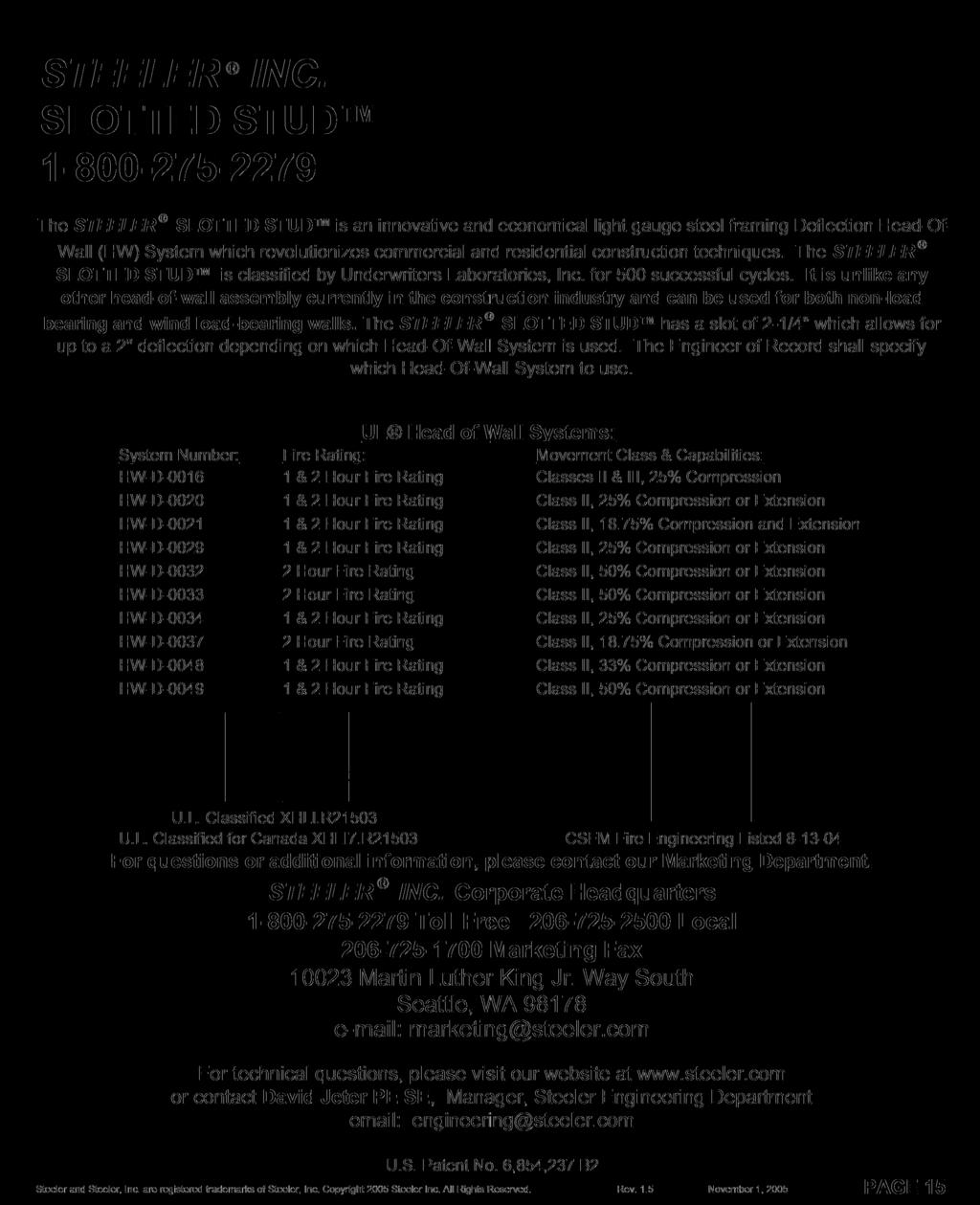
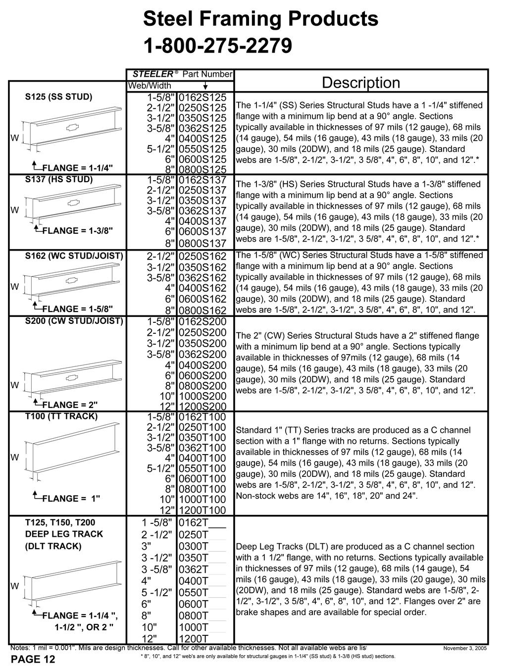
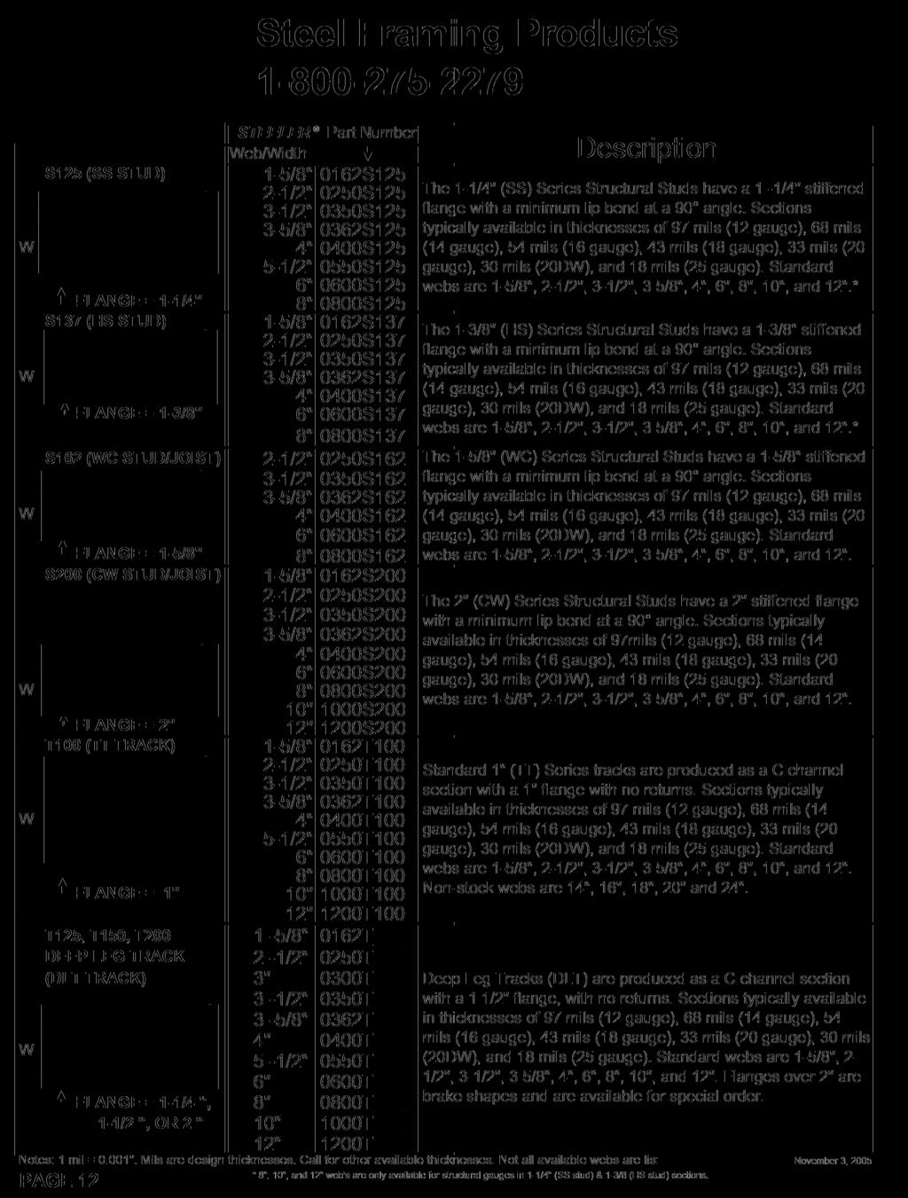
125 Steeler Slotted Stud MODERN, EFFICIENT HEAD-OF-WALL SYSTEMS A cost-effective alternative to slotted track, the Steeler Slotted Stud is everything you need in a Head-of-Wall system. The Steeler Slotted Stud is innovative and economical, as it can be used in combination with track to form both non-load bearing and wind load-bearing walls. It includes a 2 1/4" slot which allows for up to a 2" vertical deflection and is UL fire rated. Substituting Steeler Slotted Stud in place of slotted track can save your project money while still offering the proper deflection your walls require. Easier Install: Steeler Slotted Studs are lighter than conventional studs, meaning quicker installation. The 2-1/4" slot allows is designed for easy fastening. Better Deflection: Steeler Slotted Stud is unlike any other head-of-wall assembly in the industry. Its 2-1/4" slot allows for up to 2" of deflection. Superior Toughness: We use a full zinc coating to greatly minimize rust formation. What s more, the Steeler Slotted Stud is available in gauges from 21 to 12, meaning superior wind load capabilities. Designed for fire & smoke protection: Two slots in the head of each stud means less of a need for fire proofing. The Steeler Slotted Stud offers an effective alternative to standard slotted track. Depending on the specifications of your project, Steeler Slotted Studs can save you big money. Steeler Slotted Studs meet or exceed ASTM A370, A1003, C754, C645, and C955. The Steeler Slotted Stud is UL rated for up to 2 hours. Members 33ES and thicker are engineered to be load bearing and thus structural. Web Size Offerings: 1-5/8, 2, 2-1/2", 3-1/2", 3 5/8", 4", 5 1/2", 6", 8", 10, and 12. Flange Offerings: 1-1/4", 1-7/16", 1-5/8", 2, 2-1/2, and 3. For more information, including Limiting Heights and Section Properties, visit
126 STEELER INC. SLOTTED STUD Wind Load & Non-Load Bearing Deflection Wall System U.S. Patent No. 6,854,237 B2 Steeler and Steeler, Inc. are registered trademarks of Steeler, Inc. Copyright 2003 Steeler, Inc. All Rights Reserved. November 3, 2005
127 STEELER INC. SLOTTED STUD Wind Load & Non-Load Bearing Deflection Wall System U.S. Patent No. 6,854,237 B2 The Engineer of Record shall specify design vertical and lateral deflection requirements. Steeler and Steeler, Inc. are registered trademarks of Steeler, Inc. Copyright 2003 Steeler, Inc. All Rights Reserved. November 3, 2005
128
129
130
131
 699-0543 phone P (562) 695-4694 fax March 10, 2003 Mike Vailencour Steeler, Inc.")
132 ICC EVALUATION SERVICE, INC. Evaluate P Inform P Protect Los Angeles Business/Regional Office P 5360 Workman Mill Road P Whittier, CA (562) phone P (562) fax March 10, 2003 Mike Vailencour Steeler, Inc. ER-4389P Marketing and Project support Please reference this number Martin Luther King Way South on all correspondence Seattle, Washington Dear Mr. Vailencour: In reference to your request, the above-reference evaluation report dated March, 1994 continues to be in good standing under the 1991 Uniform Building Code. Reissuance of the evaluation report continues, pending acceptance of the technical revisions If you have any questions, please contact me at(562) , extension Yours very truly PB/ns Peter Bahlo Senior Staff Engineer Business/Regional Office P 5360 Workman Mill Road, Whittier, California P (562) Regional Office P 900 Montclair Road, Suite A, Birmingham, Alabama P (205) Regional Office P 4051 West Flossmoor Road, Country Club Hills, Illinois P (708)


133 Product Lines INTERIOR & EXTERIOR FRAMING Steeler Manufactured Products FASTENERS Steeler Product Offerings Steel Studs & Track Smooth Products Slotted Track Sound Resilient Channel Furring Channel Cold-Rolled Channel Angle Super Steelers * Hi-Lo Super Steelers Super Woodies * Super Framer* Super Lathers* Super Hex Framers* Super Laminating *Denotes availability in zinc coating Flat Stock Shaftwall Studs J Track Z-Furring Channel Custom Brake Shapes Steeler Slotted Studs Pony Wall Supports Rust Resistant Screws Drywall Drillers* Cement Board Screws Super Framing Drillers* Wafer Head Drillers* Super Hex Drillers* And more... INTERIOR FINISHING & DRYWALL Steeler Product Offerings TOOLS & ACCESSORIES Steeler Product Offerings Hanger Wire U-Hank Tie Wire Engineered Slide Clips National Gypsum The Steel Network Knauf Insulation Westpac Materials Products from USG Murco Wall Products Award Metals Corner Beads Trim-Tex Drywall Products And more... Bit Tips & Bit Tip Holders Magnetic Nut Runners Chop Saw Blades DeWalt Empire Levels Kett Tool Company ToolPro Pacific Laser Systems Wal-Board Tools Ramset Fastening Systems 3M Construction Supplies And more...

134 STEELER ICC-ES REPORT ESR-2054 (206) (206) FAX (800) Toll Free Martin Luther King Jr. Way South Seattle, WA Seattle Spokane Sacramento FAX FAX FAX Redmond FAX Tacoma Delta, B.C. Tucson Newark FAX FAX FAX FAX Portland Bakersfield Phoenix San Diego FAX FAX FAX FAX
SUBMITTAL SHEET. Project Submittals by
 Galvanized Tie Wire and Hanger Wire Submittal of Product Performance SUBMITTAL SHEET Project Submittals by GRABBER CONSTRUCTION PRODUCTS, INC. Submittal Date: Contract Number: Project Name: Section Number:
GLOSSARY OF TERMS SECTION 8
 GLOSSARY OF TERMS SECTION 8 Anchor Bolt Angle Base Plate Bay Blocking CCB Centerline Chord Cladding Clip Closure Strip An A-307 steel bolt embedded in the concrete footing to anchor the base plate of the
3.1 General Provisions
 WOOD FRAME CONSTRUCTION MANUAL 107 3.1 General Provisions 3.1.1 Prescriptive Requirements The provisions of this Chapter establish a specific set of resistance requirements for buildings meeting the scope
FASTENERS BUILDING DEPARTMENT
 FASTENERS BUILDING DEPARTMENT 952-446-1660 WWW.CITYOFMINNETRISTA.COM This handout is intended only as a guide and is based in part on the 2015 Minnesota Residential Code, Minnetrista City ordinances, and
*Revised September 1, 2003
 LEGACY REPORT ER-580* Reissued January, 00 ICC Evaluation Service, Inc. www.icc-es.org Business/Regional Office # 560 Workman Mill Road, Whittier, California 9060 # (56) 699-054 Regional Office # 900 Montclair
2x6. 2x8. 2x10. Size. 2-2x10 8'-5" w/ 2 NJ 7'-3" w/ 2 NJ
 1 Rafter Size Spacing Allowable span 24" 11'-9" 24" 2x6 14'-1" 2x4 12" 15'-6" 12" 24" 14'-10" 24" 2x8 18'-2" 2x6 12" 20'-5" 12" 24" 18'-2" 24" 2x10 22'-3" 2x8 12" 25'-8" 12" 24" 21'-0" 24" 2x12 25'-9"
Fastener Schedule. a, b, c. FASTENER Roof 3-8d (2 1 / ) / ) 3-10d. 3-10d ( ) 3-16d box nails. (3 1 2 toe nails on one side
 / ) 3-10d. 3-10d ( ) 3-16d box nails. (3 1 2 toe nails on one side") ITEM 1 DESCRIPTION OF BUILDING ELEMENTS Blocking between joists or rafters to top plate, toe 2 Ceiling joists to plate, toe 3 4 5 6 Ceiling joists not attached to parallel rafter, laps over partitions,
ITEM 1 DESCRIPTION OF BUILDING ELEMENTS Blocking between joists or rafters to top plate, toe 2 Ceiling joists to plate, toe 3 4 5 6 Ceiling joists not attached to parallel rafter, laps over partitions,
3. Are component and cladding design pressures consistent with ASCE 7 for the wind speed and exposure category (ASCE 7 Fig. 6-3)?
?") Mobile County Public Works Residential Plan Reviewers Checklist For Structural Requirements of Wood Framed Residences Recommendation: Permit as Noted Revise Plans and Resubmit MCPW Ref. No. Design Criteria:
Mobile County Public Works Residential Plan Reviewers Checklist For Structural Requirements of Wood Framed Residences Recommendation: Permit as Noted Revise Plans and Resubmit MCPW Ref. No. Design Criteria:
TOLL FREE:(888) FAX:(941) ASSEMBLY of ProTEC CONCRETE STRUCTURAL INSULATED PANEL
 FAX:(941) ASSEMBLY of ProTEC CONCRETE STRUCTURAL INSULATED PANEL") ASSEMBLY of ProTEC CONCRETE STRUCTURAL INSULATED PANEL The ProTEC panels are manufactured with grooves on all four sides to accept the steel components. This grooving applies to the regular panel whose
ASSEMBLY of ProTEC CONCRETE STRUCTURAL INSULATED PANEL The ProTEC panels are manufactured with grooves on all four sides to accept the steel components. This grooving applies to the regular panel whose
Garage Design Guide. October 2018
 Garage Design Guide October 2018 The Corporation of the Township of Hamilton 8235 Majestic Hills Drive, P.O. Box 1060, Cobourg Ontario K9A 4W5 Tel: 905-342-2810 Fax: 905-342-2818 Email: Tim Jeronimus (Chief
Vertical Offset Base and Safety Rail System Installation Instructions
 Section 5 Vertical Offset Base and Safety Rail System Installation Instructions The vertical offset base and safety rail assembly are designed to be used in residential construction for sloped or flat
Connectors for Cold-Formed Steel Curtain-Wall Construction
 The expiration date of this document has been extended until 2/3/3. Introducing Connectors for Cold-Formed Steel Curtain-Wall Construction Code Listed: IAPMO ES ER-238 (800) 999-5099 www.strongtie.com
ESR-1254 * DELETED BY CITY OF LOS ANGELES. Reissued April 1, 2006 This report is subject to re-examination in one year.
 ESR-1254 Reissued April 1, 2006 This report is subject to re-examination in one year. www.icc-es.org Business/Regional Office 5360 Workman Mill Road, Whittier, California 90601 (562) 699-0543 Regional
Trusted ICC ES PASLODE, Evaluation. report, or as to any. ICC-ES Evaluation
 0 ICC ES Evaluation Report ICC ES 000 (800) 423 6587 (562) 699 0543 www.icc es.orgg Most Widely Accepted and Trusted ESR 3072 Reissued 09/2018 Revised 10/2018 This report is subject to renewal 09/2020.
DW HORIZONTAL INSTALLATION
 AR-PJ-01-DW2H 2" HORIZONTAL PANEL JOINT AR-PJ-02-DW2H 2" VERTICAL PANEL JOINT AR-PJ-03-DW2H 3" HORIZONTAL PANEL JOINT AR-PJ-04-DW2H 3" VERTICAL PANEL JOINT AR-PJ-05-DW2H CUSTOM REVEAL AR-PJ-06-DW2H DW-2000S
Exterior Wall Fastener Schedule
 City of Republic Community Development Department Exterior Wall Fastener Schedule REVISION DATE: JANUARY 2017 Design and construction (2012 IRC Section R602.3): Exterior walls of wood frame construction
Dave's Glossary of Construction Terms. by Dave Osborne (www.daveosborne.com)
") Dave's Glossary of Construction Terms by Dave Osborne (www.daveosborne.com) 5/4" A thickness of decking material between 1 x 6 and 2 x 6. Although it is called 5/4 x 6, it is actually 1" thick and 5 1/2"
Dave's Glossary of Construction Terms by Dave Osborne (www.daveosborne.com) 5/4" A thickness of decking material between 1 x 6 and 2 x 6. Although it is called 5/4 x 6, it is actually 1" thick and 5 1/2"
KS SERIES - VERTICAL INSTALLATION
 CS-DS-01-KSV CS DISCLAIMER CS-PJ-01-KSV KS42SL EXPANDED PANEL JOINT CS-PJ-02-KSV KS42SL ENGAGED PANEL JOINT CS-PJ-03-KSV KS45SL EXPANDED PANEL JOINT CS-PJ-04-KSV KS45 FLAT ENGAGED PANEL JOINT CS-PJ-05-KSV
Sections & Details VOCABULARY
 1 Sections & Details VOCABULARY 1 ROOF FRAMING DETAIL RIDGE BOARD SHEATHING SHINGLES WEB FASCIA RAFTER (chord) SOFFIT SHEATHING STUD INSULATION DOUBLE TOP PLATE CEILING JOIST 2 FOUNDATION DETAIL STUD SHEATHING
GlasRoc Sheathing Type X
 Wall / Fire-Rated Systems 3-5/8" (92 mm) Steel Studs ProRoc Steel Stud System 3-5/8" (92 mm) Steel Track 3-1/2" (89 mm) Glass Fiber or Mineral Wool Insulation GlasRoc Sheathing Type X UL Design U465 Cavity
NORMAL WEIGHT CONCRETE TOTAL-LEWIS-DECK GYPSUM BOARD 2 OR 3-PLY COMPOSITE TOTALJOIST TOP CHORD CONNECTION
 GENERAL DETAILS 100 TYPICAL FLOOR CONSTRUCTION NORMAL WEIGHT CONCRETE WELDED WIRE MESH FIBERGLASS BATT INSULATION (OPTIONAL) 18 GAUGE TIE WIRE 7/8" RESILIENT CHANNEL NOTE: CEILING MAY ALSO BE SUSPENDED
Best Barns USA Assembly Book
 Best Barns USA Assembly Book Revised September 12, 2017 the Easton 12'x 16' Manufactured by Reynolds Building Systems, Inc. 205 Arlington Drive - Greenville, PA 16125 This manual is copyrighted. Under
ROOF-CEILING CONSTRUCTION
 CHAPTER 8 ROOF-CEILING CONSTRUCTION SECTION R801 GENERAL R801.1 Application. The provisions of this chapter shall control the design and construction of the roof-ceiling system for all buildings. R801.2
Carpentry/Carpenter CIP Task Grid
 1 Secondary Task List 100 SAFETY/OCCUPATIONAL ORIENTATION 101 Identify and follow all basic safety practices and procedures. 102 Identify and follow all lab safety practices and procedures. 103 Identify
Drywall, Wood and Truss Uplift
 Drywall, Wood and Truss Uplift Drywall (gypsum board) has to: provide rigidity provide aesthetics provide fire protection not leak air Concerns Wood moves. Drywall does not move. Interesting problem. The
Introducing AJSTM INSTALLATION GUIDE USA. 8 th Edition USA
 The SIMPLE FRAMING SYSTEMSM INSTALLATION GUIDE USA for Floors This Installation Guide is intended to provide general information for the designer and end-user. For further information, please refer to
 JOIST DETAILS Plate nail, 16d (0.15" x 1 ") at 1 on-center Blocking panel: 1 1 8" TJ Rim Board, 1 1 TimberStrand SL or TJI joist Toe nail, 10d (0.11" x ") at on-center A1 CS BEAM DETAILS L1 eb stiffener
A Shell construction
 A Shell construction A 4/2012 Content 1 BASE AND WALL ANCHORING 1.1 Base with mortar bed 1.2 Base with sill plate 1.3 Base with raised sill plate 1.4 Concrete base (mortar bed) 1.5 Concrete base (sill
Best Barns USA Assembly Book
 Best Barns USA Assembly Book Revised November 20, 2013 the Easton - R 12'x 16' Manufactured by Reynolds Building Systems, Inc. 205 Arlington Drive Greenville, PA 16125 724-646-3775 This manual is copyrighted.
Wood structures Copyright G G Schierle, press Esc to end, for next, for previous slide 1
 Wood structures Copyright G G Schierle, 2001-02 press Esc to end, for next, for previous slide 1 Wood Types: Balloon framing (rare) Platform framing Heavy timber framing Advantages: The only renewable
Shearwall System Installation Guide
 Shearwall System Installation Guide Complete HFX product listing with dimensions, weights, connectors, typical installations and accessories. Also includes Hardy Frame Moment Frame information. Easy as
COLD-FORMED METAL FRAMING INSPECTION REPORT SUMMARY
 COLD-FORMED METAL FRAMING INSPECTION REPORT SUMMARY Inspector: Section 05400 Name: Date: Company: Address: City: State: Zip code: Phone: Fax: E-mail: Project: Project Name: Location: Contractor: Phone:
SCREW FASTENER SELECTION FOR COLD-FORMED STEEL FRAME CONSTRUCTION
 test TECHNICAL NOTE On Cold-Formed Steel Construction $5.00 Cold-Formed Steel Engineers Institute Washington, DC www.cfsei.org 866-465-4732 SCREW FASTENER SELECTION FOR COLD-FORMED STEEL FRAME CONSTRUCTION
REPORT HOLDER: JAACO CORPORATION NORTHEAST 68 TH STREET, SUITE C-130 REDMOND, WASHINGTON EVALUATION SUBJECT:
 0 Most Widely Accepted and Trusted ICC-ES Evaluation Report ICC-ES 000 (800) 423-6587 (562) 699-0543 www.icc-es.org ESR-2961 Reissued 09/2017 This report is subject to renewal 09/2019. DIVISION: 05 00
CUTTING, NOTCHING, AND BORING OF WOOD FRAMING MEMBERS (Unless an alternate design is provided by a licensed Engineer or Architect)
") INFORMATION BULLETIN / PUBLIC - BUILDING CODE REFERENCE NO.: 91.2320 Effective: 5-23-00 DOCUMENT NO. P/BC 2002-007 Revised: 2-01-01 Previously Issued As: IB ST-14 CUTTING, NOTCHING, AND BORING OF WOOD
INFORMATION BULLETIN / PUBLIC - BUILDING CODE REFERENCE NO.: 91.2320 Effective: 5-23-00 DOCUMENT NO. P/BC 2002-007 Revised: 2-01-01 Previously Issued As: IB ST-14 CUTTING, NOTCHING, AND BORING OF WOOD
Glulam Connection Details
 T E C H N I C A L N O T E Glulam Connection Details Note: This version is superseded by a more current edition. Check the current edition for updated design and application recommendations. ENGINEERED
Best Barns USA. the Brookhaven 10' x 16' Assembly Book. revised March 23, 2016
 Best Barns USA Assembly Book revised March 23, 2016 the Brookhaven 10' x 16' Manufactured by Reynolds Building Systems, Inc. 205 Arlington Drive Greenville, PA 16125 724-646-3775 This manual is copyrighted.
CARRIER OVERHANG 1'-0" MAX PANEL LENGTH 3'-0" MIN - 16'-0" MAX (RECOMMENDED) SPECIFICATIONS (unless noted otherwise)
 SPECIFICATIONS (unless noted otherwise)") DETAIL 5 32 5 " 27 32 " 6" OPTIONAL FLAT RECESSED CLOSURE 1 1 4 " 17 32 " 1 25 32 " OPTIONAL BUTTERFLY CLOSURE CARRIER OVERHANG 1'-0" MAX CARRIER SPAN 4'-0" 12 GA HANGER WIRE, BY OTHERS, NOT BY HUNTER
DETAIL 5 32 5 " 27 32 " 6" OPTIONAL FLAT RECESSED CLOSURE 1 1 4 " 17 32 " 1 25 32 " OPTIONAL BUTTERFLY CLOSURE CARRIER OVERHANG 1'-0" MAX CARRIER SPAN 4'-0" 12 GA HANGER WIRE, BY OTHERS, NOT BY HUNTER
WOODWORKS. Linear Solid Panels. Installation Instructions CEILING SYSTEMS. 1. General
 CEILING SYSTEMS Between us, ideas become reality WOODWORKS Installation Instructions Linear Solid Panels 1. General 1.1 Product Description WoodWorks Linear features a solid wood ceiling system in 1' x
table of contents Sliding Door Accessories Page Latches & Snuggers Stay Rollers Brackets & Stops
 table of contents Square Track & Accessories Pages 4-7 Square Track Options Page 4 Light Duty Track Page 4 Square Track Brackets Page 5 Square Track Accessories Page 5 Square Track Trolleys Page 6-7 Offset
Connectors for Cold-Formed Steel Curtain-Wall Construction
 Introducing Connectors for Cold-Formed Steel Curtain-Wall Construction Code Listed: IAPMO ES ER-238 (800) 999-5099 www.strongtie.com Our Newest Product Line for Cold-Formed Steel Framing Simpson Strong
Best Barns USA Assembly Book
 Best Barns USA Assembly Book Revised September 12, 2017 the Denver 12' x 16' Manufactured by Reynolds Building Systems, Inc. 205 Arlington Drive Greenville, PA 16125 This manual is copyrighted. Under the
Best Barns USA Assembly Book
 Best Barns USA Assembly Book Revised September 19, 2017 the Millcreek 12'x 20' Manufactured by Reynolds Building Systems, Inc 205 Arlington Drive Greenville, PA 16125 This manual is copyrighted Under the
Building for High Wind Resistance in Light-Frame Wood Construction
 Building for High Wind Resistance in Light-Frame Wood Construction DESIGN GUIDE Meeting the Challenge of High Wind Design Designing a structure to withstand the devastating forces of tornados is one of
ROOF-CEILING CONSTRUCTION
 CHAPTER 8 ROOF-CEILING CONSTRUCTION SECTION R801 GENERAL R801.1 Application. The provisions of this chapter shall control the design and construction of the roof-ceiling system for all buildings (see Section
INSTALLATION SHOP DRAWINGS FOR MINNEAPOLIS, MN
 MINNEAPOLIS, MN 2-0- 2-- General Notes Abbreviations Deviations from Architectural Specifications Deviations from Architectural Drawings ALUM. = ALUMINUM B.O. = BY OTHERS CONT. = CONTINUOUS. = CLEARANCE
Best Barns USA. Assembly Book. 12'x 16' the Millcreek. Revised September 19, 2017
 Assembly Book Best Barns USA Revised September 19, 2017 the Millcreek 12'x 16' Manufactured by Reynolds Building Systems, Inc 205 Arlington Drive Greenville, PA 16125 This manual is copyrighted Under the
AUXILIARY FRAMING AND ACCESSORIES
 CUSTOM CABINETS & RACKS STRUT AND ACCESSO- RIES JUNCTION KITS ANGLE AND BRACE KITS SPLICE KITS BRACE KITS INSTALLATION KITS WALL ANGLE KITS RUBBER END CAPS SUPPORT INSTALLATION AND SUPPORT KITS STANCHION
Entry Level Assessment Blueprint Carpentry
 Entry Level Assessment Blueprint Test Code: 4115 / Version: 01 Specific Competencies and Skills Tested in this Assessment: Safety Demonstrate safe material handling practices Display comprehension of workplace/job-site
Main Floor Revisions: 38' 0" Rm1 H3 50' 0" Bk1 B1 Rm2 B5 (26)-2 H2 B2 H3 (3)-3 B3 (11)-4 Bk1 B1 (5)-5 Rm4 Bk1 Rm3 Bk1 24' 0" 6' 0" 20' 0" START FRAMIN
-2 H2 B2 H3 (3)-3 B3 (11)-4 Bk1 B1 (5)-5 Rm4 Bk1 Rm3 Bk1 24' 0 6' 0 20' 0 START FRAMIN") Main Floor Revisions: 38' 0" Rm1 H3 50' 0" B1 Rm2 B5 (26)-2 H2 B2 H3 (3)-3 B3 (11)-4 B1 (5)-5 Rm4 Rm3 24' 0" 6' 0" 20' 0" START FRAMING HERE 18" BCI 90'S @ 16"OC Products PlotID Net Qty Product Length
Main Floor Revisions: 38' 0" Rm1 H3 50' 0" B1 Rm2 B5 (26)-2 H2 B2 H3 (3)-3 B3 (11)-4 B1 (5)-5 Rm4 Rm3 24' 0" 6' 0" 20' 0" START FRAMING HERE 18" BCI 90'S @ 16"OC Products PlotID Net Qty Product Length
Best Barns USA Assembly Book Revised October 24, 2017
 Best Barns USA Assembly Book Revised October 24, 2017 Garage Door by Owner the Tahoe 12'x 16' Manufactured by Reynolds Building Systems, Inc. 205 Arlington Drive Greenville, PA 16125 This manual is copyrighted.
ICC-ES Evaluation Report Reissued September 1, 2012 This report is subject to renewal September 1, 2013.
 ICC-ES Evaluation Report www.icc-es.org (800) 423-6587 (562) 699-0543 ESR-1790 Reissued September 1, 2012 This report is subject to renewal September 1, 2013. A Subsidiary of the International Code Council
Unit 9. Wall and Ceiling Framing
 Unit 9 Wall and Ceiling Framing Wall construction Wall framing includes the assembly of horizontal and vertical members that make up exterior walls and interior partitions. Theses walls support the ceilings
Best Barns USA Assembly Book
 Best Barns USA Assembly Book Revised December 6, 2013 the Denver-R 12' x 20' Manufactured by Reynolds Building Systems, Inc. 205 Arlington Drive Greenville, PA 16125 724-646-3775 This manual is copyrighted.
Beam & Header Technical Guide. LP SolidStart LVL. 2900F b -2.0E. U.S. Technical Guide U.S. TECHNICAL GUIDE
 U.S. Technical Guide U.S. TECHNICAL GUIDE LP SolidStart LVL & Header Technical Guide 2900F b -2.0E Please verify availability with the LP SolidStart Engineered Wood Products distributor in your area prior
THE ENGINEERED WOOD ASSOCIATION
 D A T A F I L E APA Performance Rated Rim Boards A rim board is the wood component that fills the space between the sill plate and bottom plate of a wall or, in second floor construction, between the top
Coatings ASTM B117 SST Salt Spray Test Kesternick Phosphate Zinc E-Coat Dip Spin Coatings
 Head and Thread types Coatings ASTM B117 Two major types of coating tests: SST Salt Spray Test screws are placed in a container and a salt solution is sprayed on the screws for a number of hours, checking
1. Show the following information with additional information necessary to indicate shop compliance with the requirements of this section.
 SECTION 12360 LIBRARY SHELVING PART 1 GENERAL 1.01 SUMMARY A. Related Sections: 1. 06100 - Carpentry. 2. 09200 - Metal Studs, Lath, Suspension Ceiling, Plaster and Stucco. 3. 09660 - Resilient Tile Flooring.
SECTION ROUGH CARPENTRY
 SECTION 06100 PART I - GENERAL 1.01 DESCRIPTION A. Scope: Work of this Section shall include all materials and installation necessary to provide Rough Carpentry as shown and detailed on the Drawings and
Assembly Book. 10' x 12' the Cambridge II. revised June 13, 2014
 Assembly Book revised June 13, 2014 the Cambridge II 10' x 12' Manufactured by Reynolds Building Systems, Inc. 205 Arlington Drive Greenville, PA 16125 724-646-3775 This manual is copyrighted. Under the
LEGACY REPORT. (800) (562) A Subsidiary of the International Code Council. *Revised September 2003
 (562) A Subsidiary of the International Code Council. *Revised September 2003") ICC-ES Evaluation Report ER-580* Reissued January 00 www.icc-es.org (800) 4-6587 (56) 699-054 A Subsidiary of the International Code Council Legacy report on the 997 Uniform Building Code DIVISION: 05
ICC-ES Evaluation Report ER-580* Reissued January 00 www.icc-es.org (800) 4-6587 (56) 699-054 A Subsidiary of the International Code Council Legacy report on the 997 Uniform Building Code DIVISION: 05
B. Shop Drawings: Include elevations, door edge details, frame profiles, metal thicknesses, preparations for hardware, and other details.
 SECTION 081113 - HOLLOW METAL DOORS AND FRAMES PART 1 - GENERAL 1.1 SUMMARY A. Section Includes: 1. Standard hollow metal doors and frames. 1.2 SUBMITTALS A. Product Data: For each type of product indicated.
APPLICATION FOR A BUILDING PERMIT
 APPLICATION FOR A BUILDING PERMIT City of San Jacinto 595 S. San Jacinto Ave San Jacinto CA 92583 95.487.7330 fax 95.654.9896 Must print legibly, submit (3) sets of building and plot plans. Fill out all
VERSA-LAM BCI INSTALLATION GUIDE LIMIT STATES DESIGN CANADA
 INSTALLATION GUIDE VERSA-LAM BCI LIMIT STATES DESIGN CANADA The information in this document pertains use in the CANADA ONLY, Limit States Design. Refer the appropriate Specifier Guide US for use in the
ESR-2403 Reissued October 1, 2009 This report is subject to re-examination in one year.
 ICC-ES Evaluation Report ESR-403 Reissued October, 009 This report is subject to re-examination in one year. www.icc-es.org (800) 43-6587 (56) 699-0543 A Subsidiary of the International Code Council DIVISION:
Best Barns USA Assembly Book
 Best Barns USA Assembly Book Revised November 27, 2013 the Easton - R 12'x 20' Manufactured by Reynolds Building Systems, Inc. 205 Arlington Drive Greenville, PA 16125 724-646-3775 This manual is copyrighted.
CITY OF LOS ANGELES CALIFORNIA
 BOARD OF BUILDING AND SAFETY COMMISSIONERS JAVIER NUÑEZ PRESIDENT MARSHA L. BROWN VICE-PRESIDENT VAN AMBATIELOS PEDRO BIRBA ELENORE A. WILLIAMS CITY OF LOS ANGELES CALIFORNIA ANTONIO R. VILLARAIGOSA MAYOR
UL Construction No. 254
 UL Construction No. Wind-Uplift - Class 90 (See Item No. ) / Fire Not Investigated Metal Roof Deck Panels* Snap-Clad No. MSG or No. MSG min. thickness coated steel panels. Panels in. wide max., 0 in. wide
ROOF-CEILING CONSTRUCTION
 CHAPTER 8 ROOF-CEILING CONSTRUCTION SECTION R801 GENERAL R801.1 Application. The provisions of this chapter shall control the design and construction of the roof-ceiling system for all buildings. R801.2
ICC-ES Evaluation Report
 ICC-ES Evaluation Report www.icc-es.org (800) 423-6587 (562) 699-0543 ESR-2608 Reissued January 2016 This report is subject to renewal January 2017. A Subsidiary of the International Code Council DIVISION:
Assembly Book. 10' x 16' the Cambridge II. revised July 15, 2014
 Assembly Book revised July 15, 2014 the Cambridge II 10' x 16' Manufactured by Reynolds Building Systems, Inc. 205 Arlington Drive Greenville, PA 16125 724-646-3775 This manual is copyrighted. Under the
SYNTHEON ACCEL-E INSTALLATION MANUAL
 Installation Guide SYNTHEON ACCEL-E INSTALLATION MANUAL Table of Contents View this entire installation manual online at www.syntheoninc.com/accel-e GENERAL INFORMATION... 2-11 Introduction...2 ACCEL-E
APA Performance Rated Rim Boards
 D a t a F i l e APA Performance Rated Rim Boards A Rim Board is the wood component that fills the space between the sill plate and bottom plate of a wall or, in second floor construction, between the top
eco-shake INSTALLATION INSTRUCTION
 1 eco-shake INSTALLATION INSTRUCTION NOTE: Shuffling the eco-shakes during installation may be necessary to obtain a uniform color throughout the roof. Due to the natural wood content in the ecoshakes,
Best Barns USA Assembly Book
 Best Barns USA Assembly Book Revised February 4, 2016 the Millcreek-R 12'x 20' Manufactured by Reynolds Building Systems, Inc. 205 Arlington Drive Greenville, PA 16125 724-646-3775 This manual is copyrighted.
Best Barns USA Assembly Book
 Best Barns USA Assembly Book Revised February 4, 2016 the Millcreek-R 12'x 16' Manufactured by Reynolds Building Systems, Inc. 205 Arlington Drive Greenville, PA 16125 724-646-3775 This manual is copyrighted.
Featuring TJ Rim Board and TimberStrand LSL
 #TJ-8000 SPECIFIER S GUIDE TRUS JOIST RIM BOARD Featuring TJ Rim Board and TimberStrand LSL Multiple thicknesses, grades, and products to cover all your rim board needs 1¼" Thickness matches lateral load
Hardware Pkg
 ASSEMBLY INSTRUCTIONS Horse Shelter 12 x 15 76110678 Hardware Pkg. 76900228 THANK YOU FOR PURCHASING THIS PRODUCT For questions about this product, or parts inquiries, please contact our Customer Service
SECTION: 15 ZONING RULE LOT AREA 6134 S.F S.F. BUILDING AREA (FOOTPRINT) LOT COVERAGE 20.2% 24.86' FRONT YARD SIDE YARD 8.
 LOT COVERAGE 20.2% 24.86' FRONT YARD SIDE YARD 8.") PROPOSED 1ST FLOOR PROPOSED 2ND FLOOR Anthony Hatziioannou Architect, P.C. EXISTING 1ST FLOOR ZONING CALCULATION JURISDICTION: TOWN OF OYSTER BAY SECTION: 15 BLOCK: 71 LOT: ZONE: RESIDENCE R1-7 PERMITTED
PROPOSED 1ST FLOOR PROPOSED 2ND FLOOR Anthony Hatziioannou Architect, P.C. EXISTING 1ST FLOOR ZONING CALCULATION JURISDICTION: TOWN OF OYSTER BAY SECTION: 15 BLOCK: 71 LOT: ZONE: RESIDENCE R1-7 PERMITTED
Assembly Book. the Brandon Building Size 12' x 20' Revised September 13, 2017
 Assembly Book Revised September 13, 2017 the Brandon Building Size 12' x 20' Manufactured by Reynolds Building Systems, Inc. 205 Arlington Drive Greenville, PA 16125 This manual is copyrighted. Under the
900 SERIES WALL PANELS
 CI-DS-01-900 CI-PP-01-900 CI-PJ-01-900 CI-PJ-02-900 CI-PJ-03-900 CI-BS-01-900 CI-BS-02-900 CI-BS-03-900 CI-BS-04-900 CI-BS-05-900 CI-OC-01-900 CI-OC-02-900 CI-IC-01-900 CI-FO-01-900 CI-FO-02-900 CI-FO-03-900
COMPOSITE SIDING INSTALLATION GUIDE
 CENTURY HOME LIVING COMPOSITE SIDING INSTALLATION GUIDE Read all instructions prior to installing any siding product. Failure to install and finish this product in accordance with all local building codes,
With Illustrations, Drawings & Step By Step Details. Click Here To Download 12,000 Shed Plans. 1 P a g e Download 12,000 More Shed Plans
 With Illustrations, Drawings & Step By Step Details Click Here To Download 12,000 Shed Plans 1 P a g e Download 12,000 More Shed Plans Table of Contents OVERVIEW... 3 MATERIALS & CUTTING LISTS... 4 DRAWINGS,
Best Barns USA Assembly Book
 Best Barns USA Assembly Book Revised July 6, 2015 Garage Door by Owner Tahoe-R 12'x 20' Manufactured by Reynolds Building Systems, Inc. 205 Arlington Drive Greenville, PA 16125 724-646-3775 This manual
Best Barns USA Assembly Book
 Best Barns USA Assembly Book Revised September 19, 2017 Garage Door by Owner the Tahoe 12'x 20' Manufactured by Reynolds Building Systems, Inc. 205 Arlington Drive Greenville, PA 16125 This manual is copyrighted.
FIRE STATION NO TH STREET NORTH ST. PETERSBURG, FL M-1 SCOPE OF WORK SYMBOL DESCRIPTION SYMBOL DESCRIPTION HVAC SYMBOL LEGEND
 HVAC SYMBOL LEGEND HVAC PIPING AND VALVES LEGEND HVAC GENERAL NOTES SCOPE OF WORK SYMBOL DESCRIPTION SYMBOL DESCRIPTION SYMBOL DESCRIPTION SYMBOL DESCRIPTION PHASING OF WORK HVAC ABBREVIATIONS ABBREVIATION
Core Curriculum Carpentry 1 Carpentry 2 Carpentry 3
 A Correlation of Core Curriculum Carpentry 1 Carpentry 3 To the Carpentry II Course Standards and Objectives to the Content Standards Resource Title: Core Curriculum: Introductory Craft Skills, Fifth Edition
8 x 10 Timber-frame Garden Shed
 8 x 10 Timber-frame Garden Shed Includes: Step-By-Step Instructions, Complete Details & Materials Lists Timber-framing is a traditional building method that uses a simple framework of heavy timber posts
Mach Wall Installation Instructions
 Mach Wall Installation Instructions Planning the Job Since Mach Wall is an innovative product that accomplishes 3 tasks at the same time (frame, insulate and drywall) and it replaces traditional framing,
Strands & Standards CARPENTRY 2
 Strands & Standards CARPENTRY 2 COURSE DESCRIPTION This is the second in a sequence of courses that prepares individuals to layout, fabricate, erect, install, and repair wooden structures and fixtures
PART II ENGINEERED BASIS OF RIDGE AND EAVE VENT DETAILS
 PART II ENGINEERED BASIS OF RIDGE AND EAVE VENT DETAILS A - INTRODUCTION This report addresses engineered design for unblocked wood structural panel (plywood or OSB) roof diaphragms with either continuous
Best Barns USA Assembly Book
 Best Barns USA Assembly Book Revised September 13, 2017 the Belmont Building Size 12' x 16' Manufactured by Reynolds Building Systems, Inc. 205 Arlington Drive Greenville, PA 16125 This manual is copyrighted.
METALWORKS Linear (Interior & Exterior Applications)
") CEILING&WALL SYSTEMS Between us, ideas become reality METALWORKS Linear (Interior & Exterior Applications) Assembly and Installation Instructions 1. GENERAL 1.1 Product Description MetalWorks Linear is
CEILING&WALL SYSTEMS Between us, ideas become reality METALWORKS Linear (Interior & Exterior Applications) Assembly and Installation Instructions 1. GENERAL 1.1 Product Description MetalWorks Linear is
Horse Shelter 12 x
 Horse Shelter 12 x 15 76110678 Hardware Kit 76900228 THANK YOU FOR PURCHASING THIS PRODUCT Behlen Country has been in the business of providing quality products for more than 75 years. Our products will
6x6 Shed Plans and Building Guide
 Page 1 Legal 2018 Zac Spade & Christopher D. Brown. All Rights Reserved For information about special discounts available for bulk purchases, sales promotions, fundraising and educational needs, contact
ROOF-CEILING CONSTRUCTION
 CHAPTER 8 ROOF-CEILING CONSTRUCTION SECTION R801 GENERAL R801.1 Application. The provisions of this chapter shall control the design and construction of the roof-ceiling system for all buildings. R801.2
A. Rough carpentry includes but is not limited to the following:
 SECTION 06100 ROUGH CARPENTRY PART 1 - GENERAL 1.01 RELATED DOCUMENTS A. Drawings and general provisions of Contract, including General and Supplementary Conditions and Division-1 Specification Sections,
Best Barns USA. the Danbury - R 8' x 12' Assembly Book. Revised September 30, 2016
 Best Barns USA Assembly Book Revised September 30, 2016 the Danbury - R 8' x 12' Manufactured by Reynolds Building Systems, Inc. 205 Arlington Drive Greenville, PA 16125 724-646-3775 This manual is copyrighted.
Best Barns USA Assembly Book
 Best Barns USA Assembly Book Revised September 19, 2016 the Meadowbrook-R 16' x 10' Manufactured by Reynolds Building Systems, Inc. 205 Arlington Drive Greenville, PA 16125 724-646-3775 This manual is
DUTCH GABLE FREESTANDING CARPORT
 DUTCH GABLE FREESTANDING CARPORT STRATCO OUTBACK ASSEMBLY INSTRUCTIONS. Your complete guide to building a FREESTANDING Outback DUTCH GABLE CARPORT BEFORE YOU START Carefully read these instructions. If