FIRE STATION NO TH STREET NORTH ST. PETERSBURG, FL M-1 SCOPE OF WORK SYMBOL DESCRIPTION SYMBOL DESCRIPTION HVAC SYMBOL LEGEND
|
|
|
- Easter Wiggins
- 5 years ago
- Views:
Transcription
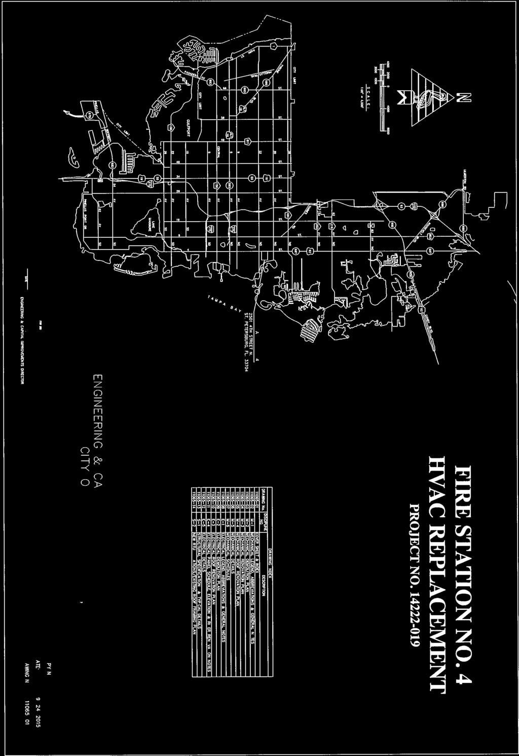

1
2 HVAC SYMBOL LEGEND HVAC PIPING AND VALVES LEGEND HVAC GENERAL NOTES SCOPE OF WORK SYMBOL DESCRIPTION SYMBOL DESCRIPTION SYMBOL DESCRIPTION SYMBOL DESCRIPTION PHASING OF WORK HVAC ABBREVIATIONS ABBREVIATION DESCRIPTION ABBREVIATION DESCRIPTION ABBREVIATION DESCRIPTION ABBREVIATION DESCRIPTION MISCELLANEOUS SYMBOLS NOTE: SOME SYMBOLS AND ABBREVIATIONS SHOWN MAY NOT PERTAIN TO THIS PROJECT. Drawn JWY Designed JWY DATE: SCALE: NOT TO SCALE DRAWING No M-1
3 GENERAL NOTES: KEYED NOTES: MECHANICAL DEMOLITION PLAN NORTH SCALE : 1/4" = 1'-0" Drawn JWY Designed JWY DATE: SCALE: 1/4" = 1'-0" DRAWING No M-2
4 GENERAL NOTES: KEYED NOTES: MECHANICAL RENOVATION PLAN NORTH SCALE : 1/4" = 1'-0" Drawn JWY Designed JWY DATE: SCALE: 1/4" = 1'-0" DRAWING No M-3
5 ROOF MOUNTED PIPE SUPPORT DETAIL GENERAL NOTES: KEYED NOTES: MECHANICAL ROOF RENOVATION PLAN NORTH SCALE : 1/4" = 1'-0" Drawn JWY Designed JWY DATE: SCALE: 1/4" = 1'-0" DRAWING No M-4
6 FIBERGLASS BLANKET DUCT INSULATION DETAIL ROOFTOP UNIT CURB TIE-DOWN DETAIL TURNING VANES DETAIL CONDENSATE DRAIN TRAP DETAIL DUCT RUNOUT TO DIFFUSER DETAIL DUCTWORK SUPPORT DETAIL DUCTWORK FITTINGS DETAIL Drawn JWY Designed JWY DATE: SCALE: NOT TO SCALE DRAWING No M-5
7 PACKAGED DX APPLIED ROOFTOP UNIT SCHEDULE AIR DEVICE SCHEDULE RTU / EXHAUST FAN INTERLOCK SCHEDULE ASHRAE OUTSIDE AIR CALCULATION COMMERCIAL Standard 8-wire twisted net cable Twisted Pair, 22 AWG. Typical Twisted Pair, 18 AWG. Typical Standard 8-wire twisted net cable RTU CONTROLS Drawn JWY Designed JWY DATE: SCALE: NOT TO SCALE DRAWING No M-6
8 ELECTRICAL SYMBOL LEGEND ELECTRICAL GENERAL NOTES: ABBREVIATIONS: NATIONAL ELECTRIC CODE NOTES: ELECTRICAL SUBMITTAL NOTES: RHM RHM Drawn RHM Designed RHM DATE: SCALE: NO SCALE DRAWING No E-1
9 POWER DEMO NOTES: NORTH ELECTRICAL DEMOLITION PLAN SCALE : 1/4" = 1'-0" Drawn RHM Designed RHM DATE: SCALE: 1/4" = 1'-0" DRAWING No E-2
10 POWER RENO NOTES: ELECTRICAL ROOF RENOVATION PLAN NORTH SCALE : 1/4" = 1'-0" Drawn RHM Designed RHM DATE: SCALE: 1/4" = 1'-0" DRAWING No E-3
11 LOAD SUMMARY RISER RENOVATION NOTES: Drawn RHM Designed RHM BY DATE DATE: ENGINEERING and CAPITAL SCALE: NO SCALE DRAWING No E-4
12 DETAIL NOTES: RTU-1 Fed from Panel P1 AC UNIT NAMEPLATE DETAIL TYPICAL DUCT SMOKE DETECTOR WIRING DETAIL ROOFTOP UNIT ELECTRICAL SCHEME Drawn RHM Designed RHM BY DATE DATE: ENGINEERING and CAPITAL SCALE: NO SCALE DRAWING No E-5
13 STRUCTURAL SPECIFICATIONS: STRUCTURAL SPECIFICATIONS: 1. CONTRACTOR IS RESPONSIBLE TO VERIFY AND COORDINATE ALL DIMENSIONS AND DETAILS BEFORE PROCEEDING WITH WORK. ANY DISCREPANCIES MUST BE IMMEDIATELY BROUGHT TO THE ATTENTION OF THE ENGINEER. THE CONTRACTOR NOTE: PROVIDE JOIST REINFORCING IN ACCORDANCE WITH THIS DETAIL FOR ALL CONCENTRATED LOADS IN EXCESS OF 150 POUNDS THAT ARE NOT SHOWN ON THE ROOF FRAMING PLAN. C.L. OF JOIST COPE HORIZONTAL LEG EXISTING JOIST CHORD IS ALSO SOLELY RESPONSIBLE FOR INITIATING, MAINTAINING AND SUPERVISING ALL SAFETY PRECAUTIONS AND PROGRAMS IN CONNECTION WITH THE WORK. NEITHER THE CITY NOR THE DESIGN PROFESSIONALS ARE RESPONSIBLE FOR THE MEANS AND METHODS OF CONSTRUCTION OR FOR RELATED SAFETY PRECAUTIONS AND PROGRAMS. 2. TYPICAL DETAILS AND WALL SECTIONS SHOWN APPLY TO ALL SIMILAR SECTIONS AND CONDITIONS UNLESS NOTED OTHERWISE. 3. CONTRACTOR MUST FULLY BRACE AND PROTECT ALL WORK IN PROGRESS UNTIL THE STRUCTURE IS COMPLETED. 4. THE STRUCTURE AND ALL APPLICABLE COMPONENTS FOR THIS PROJECT HAVE BEEN DESIGNED IN ACCORDANCE WITH APPROPRIATE PROVISIONS OF EACH OF THE FOLLOWING: 4.1. THE 5TH EDITION (2014) FLORIDA BUILDING CODE AISC MANUAL OF STEEL CONSTRUCTION, LATEST EDITION. 5. THE FOLLOWING STRUCTURAL CONSTRUCTION DOCUMENTS MUST BE USED IN CONJUNCTION WITH ALL APPLICABLE SPECIFICATIONS AND THE CONSTRUCTION DOCUMENTS. IF THERE IS A DISCREPANCY BETWEEN DOCUMENTS, IT IS THE CONCENTRATED LOAD, SEE NOTE 3" MINIMUM TYPICAL EACH END EACH ANGLE 1/8" 1-1/2" 1/8" 1-1/2" CONTRACTOR TO PROVIDE AND FIELD INSTALL L2" x 2" x 3/16" STRUT EACH SIDE OF JOIST AT ALL LOCATIONS WHERE CONCENTRATED LOAD DOES NOT OCCUR WITHIN 3" OF A PANEL POINT. INSTALL ANGLE WITH ONE END AT LOCATION OF LOAD AND OTHER END AT A PANEL POINT ON THE OPPOSITE CHORD, TYPICAL. 3" MINIMUM CONCENTRATED LOAD, SEE NOTE LENGTH A A C C B WIDTH B 1/8" 1/8" FIELD FABRICATE FRAME FROM L4" x 4" x 3/8" C.L. OF JOIST TYP PRE-ENG / PRE-FAB ADJUSTABLE 16 GA ROOF CURB. CONNECTION OF CURB TO STRUCTURE IS THE RESPONSIBILITY OF THE MECHANICAL ENGINEER 6" O/C AROUND PERIMETER OF OPENINGS 3/16" 1/8" 1/8" SECTION A-A NOT TO SCALE PRE-ENG / PRE-FAB ADJUSTABLE 16 GA ROOF CURB. CONNECTION OF CURB TO STRUCTURE IS THE RESPONSIBILITY OF THE MECHANICAL ENGINEER CONTRACTOR'S RESPONSIBILITY TO NOTIFY THE ENGINEER PRIOR TO PERFORMING ANY AND ALL CONSTRUCTION. IN CASE OF CONFLICT THE MOST STRINGENT CONDITION MUST ALWAYS APPLY. 6. IT IS THE RESPONSIBILITY OF THE CONTRACTOR TO FIELD VERIFY ALL DIMENSIONS AND COORDINATE WITH STRUCTURAL CONSTRUCTION DOCUMENTS AND WITH ANY AND ALL APPLICABLE EQUIPMENT MANUFACTURER'S (I.E. WINDOW, DOOR, AIR HANDLER, ETC.). IF THERE ARE ANY POTENTIAL CONFLICTS THE CONTRACTOR IS REQUIRED TO REQUEST AND RECEIVE A DIRECTIVE FROM THE ENGINEER PRIOR TO D3 JOIST REINFORCEMENT DETAIL NOT TO SCALE Joist Reinforcement Detail SCALE: 3/4" = 1 0" PLAN VIEW NOT TO SCALE SECTION B-B NOT TO SCALE RTU SUPPORT FRAMES FOR NEW ROOF PENETRATIONS IN EXISTING ROOF NOT TO SCALE SECTION C-C NOT TO SCALE 6" O/C AROUND PERIMETER OF OPENINGS PERFORMING WORK. 7. IF THERE ARE ANY DIMENSION'S NOT SHOWN ON THE STRUCTURAL CONSTRUCTION DOCUMENTS REQUIRED FOR CONSTRUCTION THE CONTRACTOR MAY REFER TO TYPICAL RTU CURB TO SUPPORT ANGLE FRAME DETAIL TYPICAL RTU CURB TO SUPPORT ANGLE FRAME DETAIL TYPICAL RTU CURB TO SUPPORT ANGLE FRAME DETAIL CONTACT THE ENGINEER FOR ADDITIONAL INFORMATION. STRUCTURAL STEEL: 1. ALL STRUCTURAL STEEL ELEMENTS SHALL BE HOT-DIPPED GALVANIZED AND SHALL BE FABRICATED AND ERECTED IN ACCORDANCE WITH THE LATEST A.I.S.C. SPECIFICATIONS. 2. STRUCTURAL STEEL ELEMENTS SHALL CONFORM TO THESE SPECIFICATIONS: ANCHOR BOLTS ASTM F1554 FRAMING BOLTS ASTM A325 OR A490 SHAPES (C,L,PL,T) ASTM A36 SHEAR STUDS ASTM A108 STEEL PIPE (HSS) ASTM A500 (42 KSI) STRUCTURAL TUBE (HSS) ASTM A500 (46 KSI) WELDING ELECTRODES E70XX WIDE FLANGE (WF) ASTM A992 (50 KSI) 3. SHOP CONNECTIONS MAY BE WELDED OR FASTENED BY HIGH STRENGTH BOLTS. ALL CONNECTIONS SHALL CONFORM TO STANDARD CONNECTION DETAILS ON THE PLANS, UNLESS EXPLICIT APPROVAL FROM THE ENGINEER HAS BEEN OBTAINED. ALL CONNECTIONS TO BE DOUBLE ANGLE FRAMED BEAM CONNECTION PER A.I.S.C. UNLESS NOTED OTHERWISE. 2" MAX 12" O/C MAX 12" O/C MAX 12" O/C 2" MAX 12" O/C 2" MAX 12" O/C MAX 12" O/C MAX 12" O/C TYPICAL RTU UNIT MAX WEIGHT = 1,500LBS MAX HEIGHT = 6'-0" COORDINATE DIMENSIONS OF UNIT WITH MECH. ENG. 2" LENGTH & WIDTH ANGLE FRAME TO MATCH LENGTH & WIDTH OF RTU LOCATION OF 1/4"Ø x 2 1/2" HILTI SELF-DRILLING SCREWS, THROUGH METAL DECK INTO STEEL ANGLE, TYPICAL. STEEL ROOF JOIST OR BEAM, SEE PLAN FOR SIZE AND LOCATION ATTACH CURB TO STEEL ANGLES WITH 1/4" x 2.5" HILTI SELF DRILLING 12" O/C AROUND PERIMETER. FASTENERS MUST START WITH 2" OF THE ENDS OF ALL SIDE OF THE CURB. TYPICAL RTU UNIT MAX WEIGHT = 1,500LBS MAX HEIGHT = 6'-0" PROVIDE JOIST REINF. AT CONCENTRATED LOAD LOCATIONS PER "JOIST REINFORCEMENT DETAIL", TYPICAL. GASKET, REFER TO MECHANICAL DRAWINGS. PRE-ENG / PRE-FAB ADJUSTABLE 16 GA ROOF CURB. G.C. MUST PROVIDE 2x BLOCKING UNDER DECK AT LOCATION OF CURB, WHERE APPLICABLE. ATTACH CURB TO STEEL ANGLES WITH 1/4" x 2.5" HILTI SELF DRILLING 12" O/C AROUND PERIMETER. FASTENERS MUST START WITH 2" OF THE ENDS OF ALL SIDE OF THE CURB. TYPICAL RTU UNIT MAX WEIGHT = 1,500LBS MAX HEIGHT = 6'-0" STEEL ANGLE FRAME, SEE TYPICAL DETAIL. REQUIRED AT ALL RTU LOCATIONS. GASKET, REFER TO MECHANICAL DRAWINGS. PRE-ENG / PRE-FAB ADJUSTABLE 16 GA ROOF CURB. DECK MUST BE WELDED TO ANGLE FRAME 36-7 (EACH FLUTE TO ANGLE) 4. DESIGN CONNECTIONS FOR THE MAXIMUM SHEAR (V IN KIPS) LISTED IN THE TABLES FOR "ALLOWABLE UNIFORM LOADS IN KIPS FOR BEAMS LATERALLY SUPPORTED", AT THE BOTTOM OF EACH PAGE IN THE "PROPERTIES AND REACTION VALUES", OF PART TWO OF THE LATEST EDITION OF THE A.I.S.C. "MANUAL OF STEEL CONSTRUCTION". 5. ALL BOLTS SHALL BE A MINIMUM OF 3/4" IN DIAMETER, AND BE PROVIDED WITH CURB ATTACHMENT - PLAN VIEW NOTES: 1. CONTRACTOR IS TO PROVIDE FRAME UNDER ALL RTU'S 2. CONTRACTOR MUST CONTACT THE ENGINEER IF UNIT EXCEEDS MAXIMUM HEIGHT AND/OR WEIGHT. CURB ATTACHMENT PARALLEL TO DECK SPAN. NOTES: 1. CONTRACTOR IS TO PROVIDE FRAME UNDER ALL RTUs. 2. CONTRACTOR MUST CONTACT THE ENGINEER IF UNIT EXCEEDS MAXIMUM HEIGHT AND/OR WEIGHT. CURB ATTACHMENT PERPINDICULAR TO DECK SPAN. NOTES: 1. CONTRACTOR IS TO PROVIDE FRAME UNDER ALL RTUs. 2. CONTRACTOR MUST CONTACT THE ENGINEER IF UNIT EXCEEDS MAXIMUM HEIGHT AND/OR WEIGHT. HARDENED WASHERS UNDER THE TURNED ELEMENT (BOLT HEAD OR NUT). 6. ALL CONNECTIONS PERFORMED IN THE FIELD SHALL BE MADE WITH HIGH STRENGTH BOLTS, SLIP-CRITICAL (FRICTION) TYPE. 7. INSTALLATION AND TIGHTENING OF ALL HIGH STRENGTH BOLTS MUST CONFORM TO "SPECIFICATION FOR STRUCTURAL JOINTS USING ASTM A325 OR A490 BOLTS". 8. ALL WELDING OPERATIONS MUST CONFORM TO THE AMERICAN WELDING SOCIETY CODE, ANS01.1, AND ALL WELDS SHALL BE PERFORMED USING E70XX, U.N.O. WELDS ARE TO BE EQUAL IN STRENGTH TO SIMILAR BOLTED CONNECTIONS. 9. WELDING STRUCTURAL STEEL MEMBERS TO EMBED PLATES IN CONCRETE MUST BE PERFORMED WITH EXTREME CARE. OVERHEATING THE EMBED PLATE DURING THE WELDING PROCESS WILL CAUSE SEVERE DEGRADATION OF THE PERFORMANCE OF THE CONNECTION. WELD IN SHORT, SINGLE PASSES (NO MORE THAN 6" OF LENGTH FOR 1/4" THICK WELD), AND ALLOW AMPLE COOLING-OFF TIME BETWEEN EACH WELD. THICKER WELDS SHOULD BE PERFORMED IN MULTIPLE PASSES, WITH A COOLING-OFF PERIOD FOR EACH PASS. 10. GALVANIZE ALL STEEL MEMBERS EXPOSED TO WEATHER (SUCH AS LINTELS, DOOR JAMBS, ETC.). 11. CUTS, HOLES, COPINGS, AND ALL OTHER MODIFICATIONS REQUIRED TO BE MADE FOR THE WORK OF OTHER TRADES SHALL BE SHOWN IN THE STRUCTURAL STEEL SHOP DRAWINGS, AND SHALL BE PERFORMED ONLY BY THE SHOP ISSUING SAID DRAWINGS, OR OTHER FACILITY APPROVED BY THE ENGINEER TO PERFORM SAID WORK. HOLES IN STRUCTURAL ELEMENTS SHALL BE REINFORCED AS REQUIRED BY THE ENGINEER. 12. CUTTING, BURNING OF HOLES, OR OTHER MODIFICATIONS TO STEEL MEMBERS IN THE FIELD IS NOT PERMITTED WITHOUT THE EXPLICIT APPROVAL OF THE ENGINEER. 13. STEEL MEMBERS REQUIRED BY OTHER TRADES TO SUPPORT THEIR EQUIPMENT, WHICH ARE NOT ALREADY PRESENT ON THE STRUCTURAL DRAWINGS, SHALL BE PROVIDED BY THE TRADE REQUIRING SUCH WORK. 14. ANY PROPOSED REVISIONS CONTEMPLATED BY THE CONTRACTOR TO THESE STRUCTURAL DETAILS OR ANY ALTERNATIVE DESIGN(S) FOR MODIFYING THE EXISTING STRUCTURAL ROOF SUPPORT SYSTEM FOR ENABLING SUPPORT AND INSTALLATION OF NEW ROOF MOUNTED EQUIPMENT SHALL BE SUBMITTED AS SHOP DRAWINGS AND SHALL BE PREPARED, DESIGNED, AND SIGNED AND SEALED BY A FLORIDA LICENSED PROFESSIONAL ENGINEER SHOWING ALL DETAILS AND ALL DESIGN LOAD CALCULATIONS. FULLONE STRUCTURAL GROUP 9600 KOGER BOULEVARD, SUITE #227 ST. PETERSBURG, FLORIDA PHONE: (727) FAX: (727) EB: # PROJECT#: Drawn Designed Fullone Structural Group EB: # Joseph P. Fullone, P.E. FL. PE: # Signature Date DATE: STRUCTURAL SPECIFICATIONS & SCALE: 3/4" = 1'-0" TYPICAL DETAILS DRAWING No S-1
14 EXISTING J-3 EXISTING J-3 EXISTING J-3 EXISTING J-3 EXISTING J-3 EXISTING A-1 EXISTING J-2 EXISTING J-2 EXISTING J-2 EXISTING J-2 EXISTING J-2 EXISTING J-2 EXISTING J-1 EXISTING J-1 EXISTING J-1 EXISTING J-1 EXISTING J-1 EXISTING J-1 RTU-1 MAX WEIGHT= 1,400 LBS NEW ROOF TOP UNIT (RTU) SEE MECHANICAL FOR SIZE AND WEIGHT, SEE TYPICAL DETAILS FOR CONN. OF NEW TO EXISTING ROOF. CENTER UNIT OVER EXISTING MASONRY WALL, AS SHOWN. NEW ROOF TOP UNIT (RTU) SEE MECHANICAL FOR SIZE AND WEIGHT, SEE TYPICAL DETAILS FOR CONN. OF NEW TO EXISTING ROOF. CENTER UNIT OVER EXISTING MASONRY WALL, AS SHOWN. RTU-3 MAX WEIGHT= 1,300 LBS RTU-2 MAX WEIGHT= 1,400 LBS EXISTING J-6 EXISTING J-5 EXISTING J-4 EXISTING J-6 EXISTING J-5 EXISTING J-4 EXISTING J-5 EXISTING J-4 EXISTING J-6 FULLONE STRUCTURAL GROUP 9600 KOGER BOULEVARD, SUITE #227 ST. PETERSBURG, FLORIDA PHONE: (727) FAX: (727) EB: # PROJECT#: Drawn Designed Fullone Structural Group EB: # Joseph P. Fullone, P.E. FL. PE: # Signature Date DATE: NEW RTU LOCATION / SCALE: 1/4" = 1'-0" EXISTING ROOF FRAMING PLAN DRAWING No S-2
SECTION STRUCTURAL STEEL. A. PART A and DIVISION 1 of PART B are hereby made a part of this SECTION.
 SECTION 051200 PART 1 GENERAL 1.01 GENERAL REQUIREMENTS A. PART A and DIVISION 1 of PART B are hereby made a part of this SECTION. B. Examine all conditions as they exist at the project prior to submitting
3 DATE ISSUE R# Forefront Dermatology. CONFLUENCE DESIGN GROUP #2 Daniel Drive O'Fallon, MO ph: St. Peters, Missouri 63376
 THESE DRAWINGS ARE FOR THE TENANT FINISH PORTION OF THE SCOPE. LANDLORD IS RESPONSIBLE FOR THE SHELL WORK. THOSE DOCUMENTS ARE PROVIDED FOR REFERENCE ONLY New 5700 Mexico Road Suite 14 St. Peters, MO 63376
SECTION METAL FABRICATIONS
 SECTION 05100 PART 1 - GENERAL 1.01 DESCRIPTION A. Section includes specifications for metal fabrications, including minimum requirements for fabricator, and galvanizing. 1.02 REFERENCE STANDARDS A. ASTM
PLAN CEILING FRAMING PLAN CEILING JOIST SCHEDULE. Tenant Improvements. UNLV Police Station Maryland Parkway.
 TYPICAL HEADER, SEE DETAIL 3/ 4 1 6 2 CEILING FRAMING PLAN SCALE: 3/16" = 1'-0" 2 2 4 600S162-43 FLAT BRACE, 4 CEILING JOIST, SEE SCHEDULE, BOXED BEAM: (2) 600S162-54 + (2)14GA TRACKS 2 CEILING JOIST SCHEDULE
A. Radius elbows with a construction radius of 1.5 the duct width are preferred to square elbows.
 SECTION 233100 DUCTWORK 1.0 Acoustical duct lining in any part of the duct system is prohibited. All ductwork requiring insulation shall be externally insulated (Refer to the Sheet Metal Ductwork Insulation
FLUOROPOLYMER COATED DUCT FOR CAUSTIC ENVIRONMENTS
 DIVISION 23 FLUOROPOLYMER COATED DUCT FOR CAUSTIC ENVIRONMENTS Part I General 1.1 Related Documents A. All terms and general provisions of contract, General and Supplementary Conditions, and Specification
Installation and Maintenance Manual IM 770-1
 Installation and Maintenance Manual IM 770-1 Group: Applied Air Systems Part Number: IM 770 Date: March 2014 Skyline Outdoor Air Handler Roof Curb Table of Contents General Description... 3 Curb-Ready
D. Thermally Sprayed Metallic Coating (Flame Spray): STD SPEC
: STD SPEC") STANDARD SPECIFICATION SECTION 05121 MISCELLANEOUS METALWORK PART 1 - GENERAL 1.01 DESCRIPTION This section includes materials, fabrication, and installation of structural steel, connecting bolts, pipes,
STANDARD SPECIFICATION SECTION 05121 MISCELLANEOUS METALWORK PART 1 - GENERAL 1.01 DESCRIPTION This section includes materials, fabrication, and installation of structural steel, connecting bolts, pipes,
1.1 RELATED DOCUMENTS
 SECTION 050505 -BEVEL RAIL ENDS PART 1- GENERAL 1.1 RELATED DOCUMENTS A. Drawings and general provisions of the contract, including General and Supplementary Conditions and Division 01 Specification Sections
NORMAL WEIGHT CONCRETE TOTAL-LEWIS-DECK GYPSUM BOARD 2 OR 3-PLY COMPOSITE TOTALJOIST TOP CHORD CONNECTION
 GENERAL DETAILS 100 TYPICAL FLOOR CONSTRUCTION NORMAL WEIGHT CONCRETE WELDED WIRE MESH FIBERGLASS BATT INSULATION (OPTIONAL) 18 GAUGE TIE WIRE 7/8" RESILIENT CHANNEL NOTE: CEILING MAY ALSO BE SUSPENDED
TECHNICAL CORRECTION October Process Industry Practices Structural. PIP STF05121 Fabrication and Installation of Anchor Bolts
 TECHNICAL CORRECTION October 2006 Process Industry Practices Structural PIP STF05121 Fabrication and Installation of Anchor Bolts PURPOSE AND USE OF PROCESS INDUSTRY PRACTICES In an effort to minimize
Bidders and Others to Whom Bidding Documents have been issued by the Architect and/or CM.
 ADDENDUM NO. March 3, 202 Re: MCC Student Center Addition, Manchester, NH To: Bidders and Others to Whom Bidding Documents have been issued by the Architect and/or CM. All items in this Addendum shall
DECKS. Stairway illumination Positive attachment of ledger Lateral load connection required board (R507.2) required (R ) (R311.7.
 required (R ) (R311.7.") DECKS Max. riser height-7 ¾ Min. tread depth-10 Landings required at (R311.7.5.1) (R311.7.5.2) top and bottom of stairs (R311.7.6) Notched guardrail post NOT allowed Graspable handrail required Spacing
DECKS Max. riser height-7 ¾ Min. tread depth-10 Landings required at (R311.7.5.1) (R311.7.5.2) top and bottom of stairs (R311.7.6) Notched guardrail post NOT allowed Graspable handrail required Spacing
BUILDING PLANS. BUILDING INSPECTIONS DEPARTMENT
 BUILDING PLANS BUILDING INSPECTIONS DEPARTMENT 507-537-6773 www.ci.marshall.mn.us This handout is intended only as a guide to the subject matter covered herein and is based in part on the 2015 Minnesota
SECTION LOW PRESSURE DUCTWORK
 SECTION 15841 LOW PRESSURE DUCTWORK PART 1 GENERAL 1.01 SUMMARY A. Related Sections: 1. 07270 - Firestopping and Fire and Smoke Barrier Caulking. 2. 15260 - Vibration Isolation. 3. 15280 - Thermal Insulation
GLOSSARY OF TERMS SECTION 8
 GLOSSARY OF TERMS SECTION 8 Anchor Bolt Angle Base Plate Bay Blocking CCB Centerline Chord Cladding Clip Closure Strip An A-307 steel bolt embedded in the concrete footing to anchor the base plate of the
SECTION STRUCTURAL STEEL FRAMING PART 1 - GENERAL 1.1 RELATED DOCUMENTS
 SECTION 05 12 00 - STRUCTURAL STEEL FRAMING PART 1 - GENERAL 1.1 RELATED DOCUMENTS A. Drawings and general provisions of the Contract, including General and Supplementary Conditions and Division 01 Specification
SECTION BULLET- RESISTANT DOORS
 1 SECTION 08 3950 BULLET- RESISTANT DOORS PART 1- GENERAL 1.01 SUMMARY A. This Section Includes: 1. Bullet- resistant steel door and frame systems. 2. Door hardware for bullet- resistant steel door and
B. Shop Drawings: Include elevations, door edge details, frame profiles, metal thicknesses, preparations for hardware, and other details.
 SECTION 081113 - HOLLOW METAL DOORS AND FRAMES PART 1 - GENERAL 1.1 SUMMARY A. Section Includes: 1. Standard hollow metal doors and frames. 1.2 SUBMITTALS A. Product Data: For each type of product indicated.
.1 Comply with the General Conditions of the Contract, Supplementary General Conditions and the requirements of Division 1.
 PAGE 1 PART 1 GENERAL 1.1 REFERENCE.1 Comply with the General Conditions of the Contract, Supplementary General Conditions and the requirements of Division 1. 1.2 RELATED WORK SPECIFIED ELSEWHERE.1 Installation
CSS Central Mount System
 CSS-20 Installation Manual CSS-20 Safety Notifications Below are the installation instructions for the CSS-20-2 Long Span Beam Mounting System. Please read these safety notifications prior to beginning
Installation and Maintenance Manual
 Installation and Maintenance Manual IM770 Group: pplied ir Part Number: IM770 Date: pril 2003 Roof Curb for Skyline TM Outdoor ir Handlers 2013 Daikin pplied IM 770 Page 1 Table of Contents General Description...
RAIL PANEL AT TRANSITION SECTION PLAN - POST DETAIL PLAN - TUBE SPLICE. Colorado Department of Transportation. Staff Bridge Branch
 Limits of pay length for Bridge RailType 10M (For post spacing, see Dwg. No. B ) B60610 (Use with B60610A) 8 min. 1 max. 8 min. 1 max. 10 0 Max. 10 0 Max. post spacing 10 0 Max. 2 5 Post 1 x 1 slotted
A. Rough carpentry includes but is not limited to the following:
 SECTION 06100 ROUGH CARPENTRY PART 1 - GENERAL 1.01 RELATED DOCUMENTS A. Drawings and general provisions of Contract, including General and Supplementary Conditions and Division-1 Specification Sections,
Collins Engineers Palmetto Islands County Park Boardwalk Repairs 03/28/2014 SECTION ROUGH CARPENTRY
 PART 1 GENERAL 1.1 RELATED SECTIONS SECTION 061000 ROUGH CARPENTRY A. Drawings and general provisions of the Construction Contract, including General Conditions and Division 1 Specification Sections, apply
University of Houston Master Construction Specifications Insert Project Name SECTION MECHANICAL SCOPE OF WORK PART 1 - GENERAL
 SECTION 23 00 10 - MECHANICAL SCOPE OF WORK PART 1 - GENERAL 1.1 RELATED DOCUMENTS: A. The Conditions of the Contract and applicable requirements of Division 1, "General Requirements", and Section 23 01
PRESTON HEALTH SERVICES ARCHITECT S NO. 2700
 SECTION 23 3113 - LOW PRESSURE DUCTWORK PART 1 - GENERAL 1.1 SCOPE OF WORK: A. The work required under this section includes all work necessary for a complete installation of ductwork and accessories.
B. Shop Drawings: Include elevations, door edge details, frame profiles, metal thicknesses, preparations for hardware, and other details.
 SECTION 081113 - HOLLOW METAL DOORS AND FRAMES PART 1 - GENERAL 1.1 SUMMARY A. Section Includes: 1. Standard hollow metal doors and frames. 1.2 SUBMITTALS A. Product Data: For each type of product indicated.
SECTION SHEET METAL FLASHING AND TRIM
 SECTION 07620 PART 1 - GENERAL 1.1 SUMMARY A. Section Includes: 1. Formed roof drainage sheet metal fabrications. 2. Formed low-slope roof sheet metal fabrications. 1.2 SUBMITTALS A. Shop Drawings: Show
BUILDING PLANS. BUILDING DEPARTMENT
 BUILDING PLANS BUILDING DEPARTMENT 952-446-1660 www.cityofminnetrista.com This handout is intended only as a guide and is based in part on the 2015 Minnesota Residential Code, Minnetrista City ordinances,
DIVISION 6 WOOD AND PLASTICS
 DIVISION 6 WOOD AND PLASTICS PART 1 - GENERAL 1.01 SUMMARY A. This Section includes the following: 1. Wood framing. 2. Wood supports. 3. Wood blocking. 4. Wood cants. 5. Wood nailers. 6. Wood furring.
INS A KSCR INSTALLATION INSTRUCTIONS STANDARD PROCEDURE. 1. Unpacking the KSCR Splicing the KSCR (If Required)...
...") INS-88.500-0A KSCR INSTALLATION INSTRUCTIONS STANDARD PROCEDURE 1. Unpacking the KSCR... 2 2. Splicing the KSCR (If Required)... 4 3. Assemble Curb and Rail Corners... 5 4. Install Cross Bracing (If Required)...
INS-88.500-0A KSCR INSTALLATION INSTRUCTIONS STANDARD PROCEDURE 1. Unpacking the KSCR... 2 2. Splicing the KSCR (If Required)... 4 3. Assemble Curb and Rail Corners... 5 4. Install Cross Bracing (If Required)...
Attachment of Residential Deck Ledger to Side of Metal Plate Connected Wood Truss Floor Ladder. Installation Instructions Revised 9/2/2016
 Attachment of Residential Deck Ledger to Side of Metal Plate Connected Wood Truss Floor Ladder Installation Instructions Revised 9/2/2016 SBCA has been the voice of the structural building components industry
SECTION CABLE TRAYS FOR COMMUNICATIONS SYSTEMS
 SECTION 270536 - CABLE TRAYS FOR COMMUNICATIONS SYSTEMS PART 1 - GENERAL 1.1 RELATED DOCUMENTS A. Drawings and general provisions of the Contract, including General and Supplementary Conditions and Division
INSTALLATION SHOP DRAWINGS FOR MINNEAPOLIS, MN
 MINNEAPOLIS, MN 2-0- 2-- General Notes Abbreviations Deviations from Architectural Specifications Deviations from Architectural Drawings ALUM. = ALUMINUM B.O. = BY OTHERS CONT. = CONTINUOUS. = CLEARANCE
STEEL PIPE GUIDERAIL 01/01/
 NOTES PIPE RAILING & POSTS: Pipe Rails and s shall be in accordance with ASTM A5 Grade B for standard weight pipe and ASTM A500 Grade B, C or D or ASTM A50 for structural tube. Bars for handrail supports
LOW PRESSURE STEEL DUCTWORK Mechanical Systems Insulation Outlets (HVAC) Testing and Balancing.
 Testing and Balancing.") SECTION 15841 LOW PRESSURE STEEL DUCTWORK PART 1 GENERAL 1.01 SUMMARY A. Related Sections: 1. 15180 - Mechanical Systems Insulation. 2. 15940 - Outlets (HVAC). 3. 15991 - Testing and Balancing. 1.02 SUBMITTALS
SECTION 15841 LOW PRESSURE STEEL DUCTWORK PART 1 GENERAL 1.01 SUMMARY A. Related Sections: 1. 15180 - Mechanical Systems Insulation. 2. 15940 - Outlets (HVAC). 3. 15991 - Testing and Balancing. 1.02 SUBMITTALS
SECTION STEEL LIGHTING STANDARDS. 1. Electrical conduit and fittings; Section
 02760-1 of 5 SECTION 02760 STEEL LIGHTING STANDARDS 02760.01 GENERAL A. Description Steel lighting standards shall include, but not necessarily be limited to, furnishing and installing steel lighting poles,
EMMEGI ARCHITECTURAL FENCING MASTER SPECIFICATION SECTION METAL FENCING, GATES & RAILING SYSTEM PART 1 GENERAL
 EMMEGI ARCHITECTURAL FENCING MASTER SPECIFICATION SECTION 05720 METAL FENCING, GATES & RAILING SYSTEM PART 1 GENERAL EMMEGI ARCHITECTURAL FENCING is a high quality steel fencing system comprised of a hybrid
Series Sloped glazed Curtain wall. Installation Instructions
 Series 5600 Sloped glazed Curtain wall Installation Instructions Part NO. Y308 February 2013 SECTION TABLE OF CONTENTS PAGE I. General Notes & Guidelines. 3-4 II. Gutter and Mullion Assembly.. 5 III. End
Attachment of Residential Deck Ledger to Metal Plate Connected Wood Truss Floor Systems Overview Revised 9/2/2016
 Attachment of Residential Deck Ledger to Metal Plate Connected Wood Truss Floor Systems Overview Revised 9/2/2016 SBCA has been the voice of the structural building components industry since 1983, providing
3.1 General Provisions
 WOOD FRAME CONSTRUCTION MANUAL 107 3.1 General Provisions 3.1.1 Prescriptive Requirements The provisions of this Chapter establish a specific set of resistance requirements for buildings meeting the scope
The General Provisions of the Contract, including General, Supplementary and Special Conditions, apply to the work specified in this Section.
 SECTION 23 31 13 METAL HVAC DUCTS PART 1 - GENERAL 1.1 RELATED DOCUMENTS The General Provisions of the Contract, including General, Supplementary and Special Conditions, apply to the work specified in
CSP PSYCHIATRIC SERVICES UNIT SECTION IDENTIFICATION FOR HVAC PIPING AND EQUIPMENT
 SECTION 23 05 53 IDENTIFICATION FOR HVAC PIPING AND EQUIPMENT PART 1 GENERAL 1.1 SUMMARY A. Section Includes: 1. Pipe Markers. 2. Valve Tags. 3. Equipment Nameplates. 4. Underground Marking Tape. 5. Duct
CITY OF PITTSBURG ENGINEERING DEPARTMENT CONTRACT NO A WATER TREATEMENT PLANT CAPITAL IMPROVEMENTS PHASE 1A ADDENDUM #1 FENCE AND DITCH AUGUST
 CITY OF PITTSBURG ENGINEERING DEPARTMENT CONTRACT NO. 2012-16A WATER TREATEMENT PLANT CAPITAL IMPROVEMENTS PHASE 1A ADDENDUM #1 FENCE AND DITCH AUGUST 2014 CHAIN LINK FENCE SPECIFICATIONS Chain link fence,
INS A KSR INSTALLATION INSTRUCTIONS STANDARD PROCEDURE. 1. Verify Curb Installation Required Installation Tools...
 INS-88.300-0A KSR INSTALLATION INSTRUCTIONS STANDARD PROCEDURE 1. Verify Curb Installation... 2 2. Required Installation Tools... 2 3. Unpacking the KSR... 3 4. Attach KSR Bottom Rail to Curb... 5 5. Attach
PART MATERIALS. Section Fencing Materials. Description
 PART 03000 - MATERIALS Section 03010 - Fencing Materials Description 03010.00 Scope - This section consists of the test requirements, specifications and tolerances for barbed wire, woven wire and chain
PIP STF05121 Anchor Fabrication and Installation Into Concrete
 June 2017 Structural PIP STF05121 Anchor Fabrication and Installation Into Concrete PURPOSE AND USE OF PROCESS INDUSTRY PRACTICES In an effort to minimize the cost of process industry facilities, this
Connectors for Cold-Formed Steel Curtain-Wall Construction
 The expiration date of this document has been extended until 2/3/3. Introducing Connectors for Cold-Formed Steel Curtain-Wall Construction Code Listed: IAPMO ES ER-238 (800) 999-5099 www.strongtie.com
(50 FT FT) MICHIGAN DEPARTMENT OF TRANSPORTATION 10-0" 7-6" 8-0" 6-0" Truss Depth. 3" sheets 5 & 6 of 10) DEPARTMENT DIRECTOR. Kirk T.
 MICHIGAN DEPARTMENT OF TRANSPORTATION 10-0 7-6 8-0 6-0 Truss Depth. 3 sheets 5 & 6 of 10) DEPARTMENT DIRECTOR. Kirk T.") Column truss connection (See details sheets 3 & 4 of 10) \ Span (Odd number of panels) \ Span (Even number of panels) Back truss chord Top truss chord \ Truss Chord splice Truss depth (See details \ Left
Column truss connection (See details sheets 3 & 4 of 10) \ Span (Odd number of panels) \ Span (Even number of panels) Back truss chord Top truss chord \ Truss Chord splice Truss depth (See details \ Left
REINFORCEMENT DESIGN FOR METAL BUILDING SYSTEMS
 REINFORCEMENT DESIGN FOR METAL BUILDING SYSTEMS By Donald L. Johnson, P.E. RETROFIT PROJECTS CAN BE NECESSARY FOR ANY NUMBER OF REASONS, though change in use is one of the most common. Change of use can
2. All work and materials shall be in full accordance with Local and State ordinance and with any prevailing rules and regulations.
 General Conditions: 1. Deliver all food service equipment as specified herein, including that which is reasonably inferred, with all related items necessary to complete work shown on contract drawings
SECTION ROUGH CARPENTRY
 SECTION 06100 PART I - GENERAL 1.01 DESCRIPTION A. Scope: Work of this Section shall include all materials and installation necessary to provide Rough Carpentry as shown and detailed on the Drawings and
SECTION EXPANSION FITTINGS AND LOOPS FOR HVAC PIPING
 SECTION 230516 - EXPANSION FITTINGS AND LOOPS FOR HVAC PIPING PART 1 - GENERAL 1.1 RELATED DOCUMENTS A. Drawings and general provisions of the Contract, including General and Supplementary Conditions and
SECTION HOLLOW METAL DOORS AND FRAMES
 SECTION 081113 HOLLOW METAL DOORS AND FRAMES PART 1 - GENERAL 1.1 SUMMARY A. Section Includes: 1. Standard hollow metal doors and frames. 1.2 SUBMITTALS A. Product Data: Include construction details, material
SUBMITTAL REQUIREMENTS FOR COMMERCIAL BUILDING PROJECTS
 SUBMITTAL REQUIREMENTS FOR COMMERCIAL BUILDING PROJECTS When submitting your application for Commercial projects please include the following: 1. Completed Building Permit Application with page 2 stamped
Hang-TITE Rod Hanger Screws
 Description The Hang-TITE Rod Hanger Screw is a one-piece, internally threaded anchor designed for suspending threaded rod for applications like cable-tray, pipe hanging, fire protection, and electrical
3. Are component and cladding design pressures consistent with ASCE 7 for the wind speed and exposure category (ASCE 7 Fig. 6-3)?
?") Mobile County Public Works Residential Plan Reviewers Checklist For Structural Requirements of Wood Framed Residences Recommendation: Permit as Noted Revise Plans and Resubmit MCPW Ref. No. Design Criteria:
Mobile County Public Works Residential Plan Reviewers Checklist For Structural Requirements of Wood Framed Residences Recommendation: Permit as Noted Revise Plans and Resubmit MCPW Ref. No. Design Criteria:
1.1 SUMMARY. A. This Section includes the following: 1. Loose steel lintels. 2. Shelf angles. 3. Metal floor plate. 4. Pipe bollards.
 PART 1 - GENERAL 1.1 SUMMARY A. This Section includes the following: 1. Loose steel lintels. 2. Shelf angles. 3. Metal floor plate. 4. Pipe bollards. B. See Division 5 Section "Pipe and Tube Railings"
American Safe Room. Explosion Resistant Blast Hatch with Integrated Riser
 American Safe Room Explosion Resistant Blast Hatch with Integrated Riser Drawing: ASR-50-RBH Revision: H May 17, 2012 Table of Contents Description... 3 Options... 4 Order form... 5 Option: left or right
DHS-500 IMPACT SYSTEM INSTALLATION MANUAL
 DHS-500 IMPACT SYSTEM INSTALLATION MANUAL TABLE OF CONTENTS SECTION PAGE GENERAL NOTES 3 EXTRUSION & PARTS IDENTIFICATION 4-5 DETERMINE FRAME SIZE 6 FABRICATE VERTICAL MULLIONS & FILLERS 7-8 FABRICATE
Section COUPLINGS AND COUPLING ADAPTERS. This Section covers couplings and coupling adapters for ductile iron and steel pipe.
 PART 1 GENERAL 1.01 SUMMARY Section 15155 This Section covers couplings and coupling adapters for ductile iron and steel pipe. 1.02 MEASUREMENT AND PAYMENT A. No separate payment for Work performed under
Residential Room Addition / Remodel Submittal Requirement Checklist
 City of Elko Building Department 1753 College Avenue Elko, Nevada 89801 (775) 777-7220 fax (775) 777-7229 Residential Room Addition / Remodel Submittal Requirement Checklist TWO COMPLETE SETS OF PROPERLY
6o ft (18.3 m) Southwest Windpower, Inc West Route 66 Flagstaff, Arizona USA Phone: Fax:
 Southwest Windpower, Inc West Route 66 Flagstaff, Arizona USA Phone: Fax:") 6o ft (18.3 m) sectional MONOPOLE TOWER INSTALLATION MANUAL Southwest Windpower, Inc. 1801 West Route 66 Flagstaff, Arizona 86001 USA Phone: 928.779.9463 Fax: 928.779.1485 www.skystreamenergy.com 3-CMLT-1390-01
6o ft (18.3 m) sectional MONOPOLE TOWER INSTALLATION MANUAL Southwest Windpower, Inc. 1801 West Route 66 Flagstaff, Arizona 86001 USA Phone: 928.779.9463 Fax: 928.779.1485 www.skystreamenergy.com 3-CMLT-1390-01
KOLO SHELTER Installation Instructions Parts List
 Parts List Roof Cap Rafter Upright Polycarbonate Polycarbonate Drop Polycarbonate Flange Center Weldment (Short length shown above) Polycarbonate Edge Bolt.25 x 6.5 Bolt.625 x 7.5 Threaded Rod.75 x 14
Installation Instructions
 Installation Instructions 200 Series Curtainwall 3056 WALKER RIDGE DR. NW, SUITE G WALKER, MI 49544 800-866-2227 dependable@tubeliteinc.com Revised April 2014 dependable@tubeliteinc.com Page 1 TABLE OF
ALUMINUM PIPE GUIDERAIL 01/01/
 NOTES PIPE RAILING & POSTS: Structural Tube, Pipe and Bar shall be in accordance with ASTM B22 or ASTM B429, Alloy 606-T6. End Rail 90 bends and corner bends with maximum 4-0" post spacing, may be Alloy
STANDARD SPECIFICATION FOR STEEL FRAMING FOR RAILROAD SHELTERS
 SOUTHEASTERN PENNSYLVANIA TRANSPORTATION AUTHORITY 1234 MARKET STREET, PHILADELPHIA, PA 19107 STANDARD SPECIFICATION FOR STEEL FRAMING FOR RAILROAD SHELTERS REVISION DATE SPECIFICATION # F-S-306_ DATE:
*************************************************************************************************************
 15890 DUCTWORK ************************************************************************************************************* SPECIFIER: CSI MasterFormat 2004 number: 23 33 13 *************************************************************************************************************
STRUCTURAL STEEL AND ALUMINUM PART 1 - GENERAL 1.01 SCOPE:
 SECTION 05100 STRUCTURAL STEEL AND ALUMINUM PART 1 - GENERAL 1.01 SCOPE: A. The WORK of this SECTION shall consist of furnishing all the labor, materials, and equipment necessary for installation of structural
REQUEST FOR INFORMATION
 REQUEST FOR INFORMATION Project: Junction City HS General Contractor: Corp Inc. RFI #: MVCC 0 RFI Title: Cold Framing Submittal EOR Response RFI Section: 05 40 00 Date: 0/4/07 Response Required: ASAP Information
XL MAX. Suspension System Data Center Ceiling Solutions. Assembly and Installation Instructions
 PRELUDE Top Lock XL MAX (4) #8 x 1/" Long Main Beam Sharp Point Truss Head Screws Suspension System Data Center Ceiling Solutions Assembly and Installation Instructions SYSTEM OVERVIEW The Prelude XL Max
APPENDIX FENCE GENERAL NOTES
 APPENDIX FENCE GENERAL NOTES 1. Fabric: 9 gage, 2" mesh, knuckle top and bottom, placed on the outside of posts, single fabric width for the entire height. 2. All fencing to be standard galvanized finish.
SECTION MECHANICAL IDENTIFICATION
 SECTION 15190 MECHANICAL IDENTIFICATION PART 1 GENERAL 1.01 SECTION INCLUDES A. Section Includes: 1. Nameplates. 2. Tags. 3. Stencils. 4. Pipe Markers. 1.02 SUBMITTALS A. Submit valve chart and schedule,
SWAY BRACE PIPE ATTACHMENT FIG. 010
 Function: Designed for bracing pipe against sway and seismic disturbance. The pipe attachment component of a sway brace system used in conjunction with a PHD Manufacturing structural attachment fitting,
SuperMount Series Installation instructions for SuperMount 46, 68 & 80 wall structures Bill Of Materials
 SuperMount Series Installation instructions for SuperMount 46, 68 & 80 wall structures Bill Of Materials A (4) Extension Frame B (4) Telescoping Extension C (4) Cross Brace D (3) 2"x8"x84" Wall Board E
Load Tables, Technical Data and Installation Instructions
 W22. W22. W22. W22. W22 W22.. Simpson Strong-Tie Fastening Systems Structural Wood-to-Wood Connections Including Ledgers Designed to provide an easy-to-install, high-strength alternative to through-bolting
APPLICATION FOR A BUILDING PERMIT
 APPLICATION FOR A BUILDING PERMIT City of San Jacinto 595 S. San Jacinto Ave San Jacinto CA 92583 95.487.7330 fax 95.654.9896 Must print legibly, submit (3) sets of building and plot plans. Fill out all
KO LO SH E LT E R. High Capacity and Flexibility
 KO LO SH E LT E R High Capacity and Flexibility The unique styling of our redesigned Dero Kolo Shelter will help beautify your facility and provide secure, covered bike parking for cyclists. The Kolo is
STRUCTURAL ATTACHMENTS
 Brace Structural Attachment Selection Procedure ) Determine structure to be attached to from the following: A) Concrete B) Wood Beam C) Structural Steel 2) Reference structure connection type from Appendix
Typical Deck Details
 Botetourt County guard decking ledger board fasteners existing house floor construction guard post attachment ledger board attachment to existing house s footing beam -to-beam connection post-to-beam connection
Windows Installed into Walls with Polyiso and Wood Framing. Installation Instructions Standard Method Revised 10/24/2016
 Windows Installed into Walls with Polyiso and Wood Framing Installation Instructions Standard Method Revised 10/24/2016 Background There are many acceptable ways to mount and detail windows for support
SECTION THERAPEUTIC POOL ACCESSORIES
 PART 1 - GENERAL 1.1 DESCRIPTION: SECTION 13 17 23.11 THERAPEUTIC POOL ACCESSORIES SPEC WRITER NOTES: Delete between // // if not applicable to project. Also, delete any other item or paragraph not applicable
Typical Deck Details
 Based on the 2009 Michigan Statewide Building Code guard decking ledger board fasteners existing house floor construction guard post attachment ledger board attachement to existing house s footing beam
Single-Family Dwelling Submittal Requirements
 Single-Family Dwelling Submittal Requirements The purpose of this guideline is to assist our customers in preparing for plan submittal. The items listed must be included before your plans can be accepted
SECTION CONCRETE REINFORCEMENT FOR STEAM UTILITY DISTRIBUTION
 PAGE 032015-1 SECTION 032015 PART 1 - GENERAL 1.1 RELATED DOCUMENTS A. Drawings and general provisions of the Contract, including General and Supplementary Conditions and Division 01 Specification sections,
GENERAL ISOMETRIC LAYOUT
 EXISTING OR PROPOSED WIPER WALL SUPPORT STRUCTURE GATE LID CARBATHAN HG 0 WEB GRAY LOWER PAN GRATING ALUMINUM WIPER WALL CARBATHANE HG, 90 GRAY STRUCTURAL SPECIFICATIONS:. FLOODGATE MATERIAL TO BE ALUMINUM
 JOIST DETAILS Plate nail, 16d (0.15" x 1 ") at 1 on-center Blocking panel: 1 1 8" TJ Rim Board, 1 1 TimberStrand SL or TJI joist Toe nail, 10d (0.11" x ") at on-center A1 CS BEAM DETAILS L1 eb stiffener
Featuring TJ Rim Board and TimberStrand LSL
 #TJ-8000 SPECIFIER S GUIDE TRUS JOIST RIM BOARD Featuring TJ Rim Board and TimberStrand LSL Multiple thicknesses, grades, and products to cover all your rim board needs 1¼" Thickness matches lateral load
Sheet Metal Worker Level 2
 Level 2 Unit: B1 Welding 2 (GMAW and SMAW) Level: Two Duration: 25 hours Theory: Practical: 5 hours 20 hours Overview: Upon completion of this unit of instruction the apprentice will demonstrate knowledge
KS SERIES - VERTICAL INSTALLATION
 CS-DS-01-KSV CS DISCLAIMER CS-PJ-01-KSV KS42SL EXPANDED PANEL JOINT CS-PJ-02-KSV KS42SL ENGAGED PANEL JOINT CS-PJ-03-KSV KS45SL EXPANDED PANEL JOINT CS-PJ-04-KSV KS45 FLAT ENGAGED PANEL JOINT CS-PJ-05-KSV
Technical Development Program
 Technical Development Program COMMERCIAL DISTRIBUTION SYSTEMS PRESENTED BY: Ray Chow Duct Design Level 1 Fundamentals Sales Engineer Menu Section 1 Section 2 Section 3 Section 4 Section 5 Introduction
5/16" Flange nut. Bolt Keeper Plate (8" Sq. SYS.) (3) 1/2" x 3" Hex head connector zinc plated bolt w/ washers and nut. Anchor 3" sq. 7 Ga.
 (3) 1/2 x 3 Hex head connector zinc plated bolt w/ washers and nut. Anchor 3 sq. 7 Ga.") 2 1/2" x 2 1/2" x 10 Ga. 6" 5" 4" Variable Slipbase (8" Sq. SYS.) 5/16 Corner Bolt W/ nut 5/16" Flange nut Stub Insert (8" Sq. SYS.) Bolt Keeper Plate (8" Sq. SYS.) (3) 1/2" x 3" Hex head connector zinc
2 1/2" x 2 1/2" x 10 Ga. 6" 5" 4" Variable Slipbase (8" Sq. SYS.) 5/16 Corner Bolt W/ nut 5/16" Flange nut Stub Insert (8" Sq. SYS.) Bolt Keeper Plate (8" Sq. SYS.) (3) 1/2" x 3" Hex head connector zinc
GrowSpan Series 500 Roll-Up Ends
 GrowSpan Series 500 Roll-Up Ends Photo may show a different but similar model. Doorframe materials are not included. 2016 Growers Supply All Rights Reserved. Reproduction is prohibited without permission.
City of Thousand Oaks
 TENANT IMPROVEMENT SUBMITTAL CHECKLIST SUBMIT THREE SETS OF SCALED DRAWINGS (ONE TO BE A BLACKLINE SET) WITH THE FOLLOWING INFORMATION: 1. 2. 3. 4. 5. 6. 7. 8. 9. SITE PLAN: Show building location (vicinity
TYPE J (20 FT - 40 FT) MICHIGAN DEPARTMENT OF TRANSPORTATION 10-0" 7-6" NOTE: sheet 5 & 6 of 10) DEPARTMENT DIRECTOR. Kirk T.
 MICHIGAN DEPARTMENT OF TRANSPORTATION 10-0 7-6 NOTE: sheet 5 & 6 of 10) DEPARTMENT DIRECTOR. Kirk T.") Column truss connection Chord splice (see details (See details sheets 3 & 4 of 10) s Top truss chord Free end panel 10-0" Support end panels length varies (See chart below) \ Truss Back truss chord Top
Column truss connection Chord splice (see details (See details sheets 3 & 4 of 10) s Top truss chord Free end panel 10-0" Support end panels length varies (See chart below) \ Truss Back truss chord Top
2016 AASHTO BRIDGE COMMITTEE AGENDA ITEM: 24 (REVISION 1) SUBJECT: LRFD Bridge Design Specifications: Section 6, Various Articles (2)
 SUBJECT: LRFD Bridge Design Specifications: Section 6, Various Articles (2)") 2016 AASHTO BRIDGE COMMITTEE AGENDA ITEM: 24 (REVISION 1) SUBJECT: LRFD Bridge Design Specifications: Section 6, Various Articles (2) TECHNICAL COMMITTEE: T-14 Steel REVISION ADDITION NEW DOCUMENT DESIGN
2016 AASHTO BRIDGE COMMITTEE AGENDA ITEM: 24 (REVISION 1) SUBJECT: LRFD Bridge Design Specifications: Section 6, Various Articles (2) TECHNICAL COMMITTEE: T-14 Steel REVISION ADDITION NEW DOCUMENT DESIGN
TOLL FREE:(888) FAX:(941) ASSEMBLY of ProTEC CONCRETE STRUCTURAL INSULATED PANEL
 FAX:(941) ASSEMBLY of ProTEC CONCRETE STRUCTURAL INSULATED PANEL") ASSEMBLY of ProTEC CONCRETE STRUCTURAL INSULATED PANEL The ProTEC panels are manufactured with grooves on all four sides to accept the steel components. This grooving applies to the regular panel whose
ASSEMBLY of ProTEC CONCRETE STRUCTURAL INSULATED PANEL The ProTEC panels are manufactured with grooves on all four sides to accept the steel components. This grooving applies to the regular panel whose
Beam & Header Technical Guide. LP SolidStart LVL. 2900F b -2.0E. U.S. Technical Guide U.S. TECHNICAL GUIDE
 U.S. Technical Guide U.S. TECHNICAL GUIDE LP SolidStart LVL & Header Technical Guide 2900F b -2.0E Please verify availability with the LP SolidStart Engineered Wood Products distributor in your area prior
Fastener Schedule. a, b, c. FASTENER Roof 3-8d (2 1 / ) / ) 3-10d. 3-10d ( ) 3-16d box nails. (3 1 2 toe nails on one side
 / ) 3-10d. 3-10d ( ) 3-16d box nails. (3 1 2 toe nails on one side") ITEM 1 DESCRIPTION OF BUILDING ELEMENTS Blocking between joists or rafters to top plate, toe 2 Ceiling joists to plate, toe 3 4 5 6 Ceiling joists not attached to parallel rafter, laps over partitions,
ITEM 1 DESCRIPTION OF BUILDING ELEMENTS Blocking between joists or rafters to top plate, toe 2 Ceiling joists to plate, toe 3 4 5 6 Ceiling joists not attached to parallel rafter, laps over partitions,