RELAZZO DECKING SYSTEMS. Installation guide
|
|
|
- Candace Sullivan
- 6 years ago
- Views:
Transcription

1 RELAZZO DECKING SYSTEMS Installation guide
2 RELAZZO decking systems - installation checklist The checklist is intended as an aid and does NOT replace the installation guide. Base: Gravel ballast Gradient min 10 mm/lfm Concrete blocks WPC fixing bracket possibly rubber spacers possibly WPC joining plate possibly adjustable foot possibly adjustable foot adapter possibly adjustable foot screw Alu-UK 21 x 30 fixing system Concrete slab Gradient min 10 mm/lfm possibly rubber spacers WPC fixing bracket possibly WPC joining plate possibly concrete blocks possibly adjustable foot possibly adjustable foot adapter possibly adjustable foot screw Alu-UK 21 x 30 fixing system Flat roof Gradient min 10 mm/lfm Substructure frame Rubber spacers WPC fixing bracket WPC joining plate possibly concrete blocks possibly adjustable foot possibly adjustable foot adapter possibly adjustable foot screw Alu-UK 21 x 30 fixing system Substructure: 90 installation Correct substructure clearance selected to the building min 10 mm For board joints 60 to 100 mm 45 installation Correct substructure clearance selected to the building min 10 mm For board joints 60 to 100 mm Boards: Brushing direction (print/identification groove) to a fixed building component min. 20 mm to a fixed building component min. 10 mm if board < 2 lfm for joint 3 mm/lfm Adhesive REHAU bracket system: End bracket Flush end bracket Centre bracket Quick installation clip Flex clip Finishing: End cap Adhesive Aluminium end trim Adhesive Fastening set Flexible end trim Adhesive Please note that any warranty claims are void if the installation guide is not complied with and components other than RELAZZO system components are used. Sketches and pictures are only provided for illustration purposes. 2
3 CONTENTS 1 Product Range 4 2 Important Information 8 3 General RELAZZO installation and assembly Foundation Level compensation Substructure Board 19 4 RELAZZO puro WPC substructure Custom installations Accessories 31 5 RELAZZO finello, naturo, coro, calmo WPC substructure Aluminium substructure Custom installations Accessories 48 3
 WPC joining plate (V4A stainless steel)")
4 1 PRODUCT RANGE General base Adjusting foot mm Adapter for adjusting foot mm: Rubber spacer 3, 5, 10 mm 60 mm 40 mm 50 mm 30 mm 40 mm 60 mm 30 mm 50 mm 1.7 kg / lfm 1.7 kg / lfm 1.3 kg / lfm 1.3 kg / lfm WPC substructure 60 x 40 WPC substructure 60 x 40 WPC substructure 50 x 30 WPC substructure 50 x 30 WPC fixing bracket (V4A stainless steel) WPC joining plate (V4A stainless steel) Aluminium adjustable foot screw WPC adjustable foot screw 4


5 General accessories 60 mm 40 mm Adhesive Aluminium trim 60 x 40 LED spot set RELAZZO puro solid, coro Edge fixing strip Fixing bracket RELAZZO puro (30 mm) 1.9 kg/lfm 2.6 kg/lfm 4.4 kg/lfm RELAZZO puro 30 x 140 board RELAZZO puro 30 x 194 board RELAZZO puro solid 30 x 140 board End cap 30 x 140 End cap 30 x 194 Joint cover Flush end bracket 30 WPC End bracket 30 WPC Centre bracket 30 WPC 5


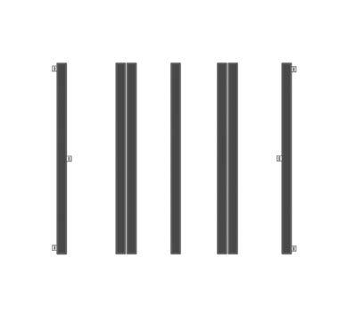
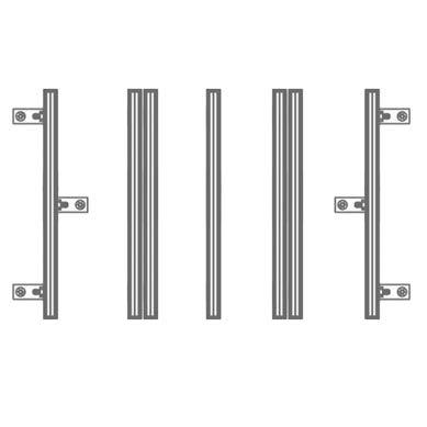
6 Aluminium step profile 30 WPC Joint filler profile 30 RELAZZO flex trim 30 RELAZZO naturo, finello, coro, calmo (23 mm) 2.3 kg/lfm 3.6 kg/lfm 0.62 kg/lfm RELAZZO naturo/finello 23 x 169 board RELAZZO coro, calmo 23 x 140 board Aluminium substructure 21 x 30 RELAZZO fixing set 21 x 30 Quick installation clip 23 aluminium Flex clip 23 aluminium End bracket 23 WPC End bracket 23 aluminium Flush end bracket 23 WPC Centre bracket 23 WPC Centre bracket 23 aluminium End cap 23 x 169 6


7 Aluminium step profile 23 aluminium Aluminium step profile 23 WPC Flex trim 23 Tool list Protective goggles Spirit level Measuring tape Chop saw Side cutter Drill Wood drill bit 2.0 mm Metal drill bit 3.5 mm, 4 mm Surface grinder Hole saw Rubber mallet 7


.")

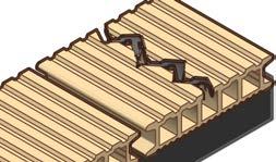
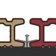
8 2 IMPORTANT INFORMATION Explanation of the icons: permitted, correct application NOT permitted, incorrect application Attension: Do not screw together directly RELAZZO boards must not be directly screwed together. Bear the installation direction in mind Ensure an even installation of the boards in brushing direction (arrow printed on board). In addition to this, pips can be seen inside cavities on hollow profiles and on the side of solid profiles to indicate the profile orientation. 8
 is to be adhered to in order to prevent water spots and")


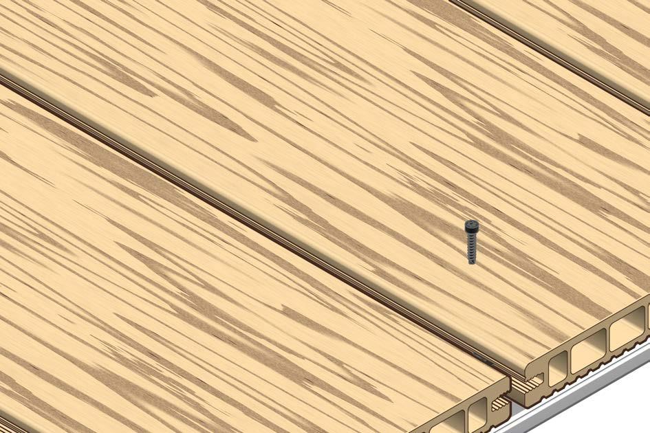
9 min. 10 mm/lfm Gradient A gradient of min. 1 % (10 mm/lfm) is to be adhered to in order to prevent water spots and waterlogging. In addition to this, the gradient also helps remove dirt naturally with rain and is very slip-resistant thanks to this. ~ 1.1 Nm Pilot drilling and screwing together Use a low torque setting so as not to over-tighten screws when screwing them in. Cut A 90 cut on the board ends is recommended for an optimum joint pattern. Boards recommended. 9
10 Bear expansion joints in mind WPC decking boards are subject to natural expansion. A sufficient expansion joint therefore has to be planned in between each board as well as the substructure. Air flow and ventilation In order to ensure quick drying of the materials underneath the boards as well as the board underside, it is mandatory to observe specified minimum clearances. Waterlogging is to be prevented. When using jointing profiles, the clearance between the subsoil and the board underside is to be increased to a minimum of 10 cm. In particular in this case, it is essential that the minimum clearances to fixed building components are maintained or increased in order to ensure sufficient air flow and ventilation. The clearance between the subsoil and the board must not be backfilled. Documentation of the installation It is recommended to photograph the decking during installation of the substructure and immediately following its completion. Document the pictures as part of the acceptance record for subsequent modifications for documentation of the ground design and the installation clearances as well as in general as evidence that this installation guide has been adhered to. Not suitable for self-supporting, structural purposes The WPC profile RELAZZO and the substructure have been specially developed for use as decking surfaces. The products do not have building authority approval and for this reason are not to be used for self-supporting or structural purposes. The local building regulations are to be observed accordingly. Colour development The raw material wood also means possible colour variations and tinges that enhance the natural wood appearance. When using different batches, it is recommended that they be mixed up so that this natural effect is used to its full potential. Safety warnings The information and recommendations given here do not release the fabricator from strict adherence to all applicable safety and environmental regulations as well as the regulations of the Labour Inspectorate and employer's liability insurance association, as these always take precedence. The safety regulations of the adhesives used must be noted and strictly observed. Auxiliary materials such as alcohol-based cleaning products and other easily flammable materials should only be stored in safe and well-ventilated places. Safety equipment such as gloves, safety goggles, ear protection and dust masks are always to be used. 10


 taking into account the local building regulations.")

11 3 RELAZZO INSTALLATION AND ASSEMBLY General installation 3.1 Foundation 3.2 At the same level 3.3 Substructure 3.4 Board 3.1 Underground Floor construction NOT allowed Load-bearing building components floor construction RELAZZO has no approval for self-supporting, structural purposes. Construction on balconies or bridges is only permitted following the approval of a structural engineer in the case of a sufficiently static subsurface (e.g. steel mesh) taking into account the local building regulations. Lawn/soil floor construction An installation on the soil or lawn is not permissible without a frost-resistant or water and erosion-resistant design of the subsoil and installation by a specialist company due to ground settlements. 11
12 Sand floor construction An installation on sand is not permissible without a frost-resistant or water and erosion-resistant design of the subsoil and installation by a specialist company due to ground settlements. Floor construction allowed Frost-resistant stone filling floor construction The local building regulations for a design of the frost-resistant stone filling in accordance with standards are to be complied with. The specialist department of your choice is responsible for the design. REHAU cannot provide a warranty for the design of the stone filling. Concrete floor construction The local building regulations for the design of the frost-resistant concrete slab in accordance with standards are to be complied with. The specialist department of your choice is responsible for the design. REHAU cannot provide a warranty for the design of the concrete slab. 12
 does not buckle due to potential loads.")
. Rubber spacers must not be")
13 Flat roof floor construction The local building regulations for the design of a flat roof in accordance with standards are to be complied with. The specialist department of your choice is responsible for the design. REHAU cannot provide a warranty for the design of the flat roof. Please ensure that the foundation (e.g. damping) does not buckle due to potential loads. 3.2 Level compensation a. Rubber spacer Rubber spacers 50 x 50 x 3, 5, 10 mm Rubber pads may be used for levelling and raising the substructure (to prevent water logging). The rubber spacers also serve the purpose of reducing noises (impact sound). Rubber spacers must not be stacked. b. Concrete spacers Concrete blocks may be used for levelling and raising the substructure (to prevent water logging). 13

 from up to 1 + 1 90 125 1 + 2 125 160 1 + 3 160 195 1 + 4 195 230 1 + 5 230 265 1 +")

14 c. Adjustable foot - The height is adjusted with millimetre precision by rotating the eight revolving fingers of the height-adjustment wheel. Note: the maximum bore height has been reached once the hole in the thread and the notch of the foot meet - The installation is carried out by placing the substructure onto the adjusting foot and fusing the fixing clips together - Pedestal: mm height adjustable - Pedestal extender: 35 mm - Floor space: Ø 200 mm - Max. allowable load per pedestal: 4 kn Adjusting foot mm Adjustable foot adapter Adjusting range (mm) from up to max. permissible total height: 510 mm WPC substructure Aluminium substructure <300 mm* <300 mm* <400 mm <400 mm <370 mm <370 mm <470 mm <470 mm *Note: if the upright WPC substructure 60 x 40 is used, the support width can be increased to 400 mm. Adjustable foot with screw for WPC substructure Adjustable foot with screw for aluminium substructure The option of fixing the foot to the notching supplied with concrete slabs exists as an alternative to screwing the adjustable foot with the foundation. 14


15 3.3 Substructure a. Installation on various bases Installation on frost-resistant stone filling The substructure profiles must not be installed directly onto the subsoil. The substructures are to be fixed onto concrete spacers with fixing bracket, fastening system aluminium substructure or onto the adjusting feet with screws. Installation on concrete The substructures located at the edge of the surface are to be fixed onto concrete base with a fixing bracket, fastening system aluminium substructure or onto the adjusting feet with screws. Uneven ground is to be levelled using rubber pads. If the substructure profiles are installed across the gradient, rubber pads, slabs (blocks, paving stones) or adjustable feet are to be used to prevent water logging. Installation on a flat roof A frame is to be built using the substructure. This frame is to be raised off the drainage membrane using rubber spacers or adjustable feet. It is forbidden to screw the substructure down. Weights/fastenings to prevent movement under wind loads must be confirmed by a specialist. Any damage to the flat roof membrane is to be ruled out! The compatibility of the rubber spacers and adjustable feet with roofing felt is to be checked. 15
16 b. Requirement table subsoil - substructure = required = optional = impermissible Gravel ballast Concrete slab Flat roof Concrete spacers Rubber base for water drainage Rubber base for levelling Assembly system for fixing to the subsoil Mounting angle for the framework construction Joining plate for substructure extension Adjustable foot 16


 = width (m) x 1.5 = min.")

17 c. General installation dimensions of the RELAZZO substructures 10 mm min. 10 mm min. max. 300 mm* max. 400 mm *Note: if the upright WPC substructure 60 x 40 is used, the support width can be increased to 400 mm. 10 mm min. 10 mm min. 10 mm min. 10 mm min. Expansion joint Expansion joint Expansion joint A Width max. 14 m A Width max. 14 m Expansion joint (mm) = width (m) x 1.5 = min. 10 mm If the width (substructure length) exceeds 14 m, an expansion joint is to be created between the substructures and the boards (joint width (mm) = min. 2 x ). 17


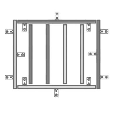
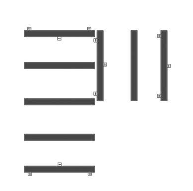
18 d. Fastening points on the subsoil/frame construction Fastening to the subsoil Frame construction Fastening the substructure to the edge of the surface and in the surface for continuous board joints. Fastening the substructure to the edge of the surface and in the surface for continuous board joints. 18
 Tip: Choose")


19 3.4 Boards The expansion joints are to be calculated according to the longest used profile length: 3 mm / lfm (in tropical or sub-tropical / humid-warm climate 4 mm / lfm) Tip: Choose profile lengths of 3 m for two or more joints in a row. Dielenlänge Dehnfuge 4 lfm 12 mm 5 lfm 15 mm 6 lfm 18 mm 10 mm min mm (5 mm for aluminium end trim ) min. 20 mm (min. 10 mm if the board 2 lfm) 20 mm min. 3 mm / lfm 3 mm / lfm 1.5 mm / lfm Towards fixed building components: min. 20 mm (min. 10 mm if board 2 lfm) Special case (longitudinal/diagonal boards): 1.5 mm/lfm) 19
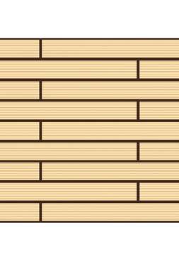
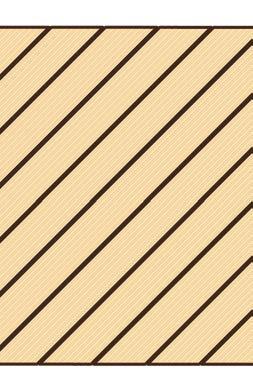
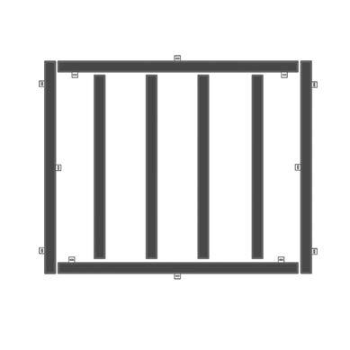
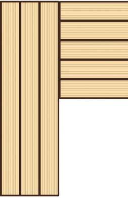
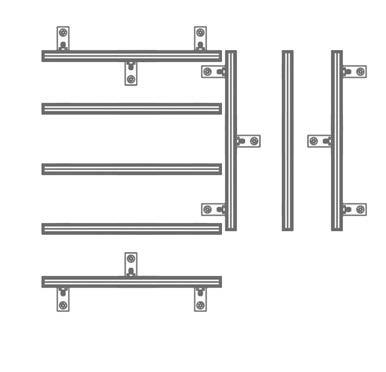
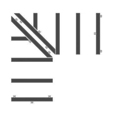
20 Installation types - substructure layout (WPC and aluminium) Brick pattern 45 The load-bearing distance for the board must be reduced by 25% if installed diagonally. Joint 20
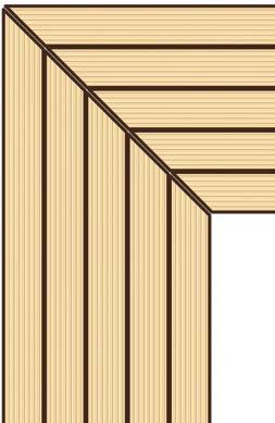
21 Mitre 21
22 4 RELAZZO PURO 4.1 WPC substructure 10 mm min. max. 500 mm max. 300 mm* *Note: if the upright WPC substructure 60 x 40 is used, the support width can be increased to 400 mm. a. Fixing the substructure (to the edge of the surface) max. 100 mm max mm max. 100 mm 22


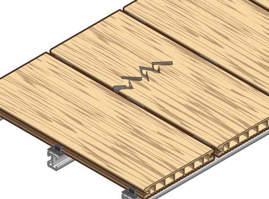
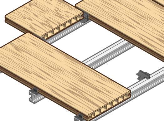
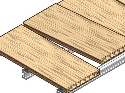
23 b. Use of brackets End bracket 10 mm min. 4.2 x 25 Centre bracket ~ 1.1 Nm 4.2 x 25 Flush end brackets 0 mm 4.2 x 25 max. 500 mm max. 50 mm 10 mm min. c. Board assembly 23


24 5 mm It is to be ensured during the installation that the screws are only screwed in halfway so that the bracket remains loose in order to also insert the subsequent boards in the same way. The screws are subsequently fully screwed in. d. Dismantling and reassembling 24
25 5 mm 25


26 26 RELAZZO DECKING SYSTEMS INSTALLATION INSTRUCTIONS


 if a step profile is used. Length Cutting 5.")

27 4.2 Custom installations The local building regulations for the design of a step geometry in accordance with standards are to be complied with. a. Step installation with WPC substructure max. 500 mm 150 mm min mm 1. Substructure design 2. Fastening the first bracket 3. Install the step riser 4. Step profile fastening It is permitted to cut the hollow section board in longitudinal direction (max. board length 80 cm) if a step profile is used. Length Cutting 5. Calculating the step Length = first bracket to the spacer block of the aluminium step profile 6. RELAZZO board pre-cuts Pre-cut part = length mm per board 7. Calculating the step 8. View of the step construction 27
 - 4 mm 2.")
 4 mm Height for pre-cut part min.")

28 b. Step installation with edge fixing angle and RELAZZO puro solid The provided countersunk head screws must be used for installing the edge fixing angle. Cut to size min. 40 mm max. 500 mm Cutting Height min. 3 screws 1. Pre-cut part calculation: Pre-cut part = (height / 2) - 4 mm 2. Fastening RELAZZO puro solid with edge fixing angle Width Cut to size min. 40 mm Cutting min. 2 screws 3. Attaching the edge fixing angle to the substructure 4. Calculation cut size: Cut size = (Width / 2) 4 mm Height for pre-cut part min. 3 screws per board min. 2 screws 5. Fastening RELAZZO puro solid with edge fixing angle 6. Fasten the fixing angle with substructure and fasten the centre bracket min. 2 screws min. 3 screws per board 7. Fastening RELAZZO puro solid with edge fixing angle 8. Fasten the fixing angle with substructure and fasten the centre bracket 28


29 c. Edging with edge fixing strip The provided countersunk head screws must be used for installing the edge fixing strip. 40 mm min. min. 2 screws min. 3 screws 1. Fastening with RELAZZO edge fixing strip 2. Attaching the edge fixing strip to the substructure max. 500 mm 3. Screwing the centre bracket onto the next RELAZZO board d. Edging with edge fixing angle The provided countersunk head screws must be used for installing the edge fixing angle. min. 70 mm Cutting min. 2 screws min. 3 screws per board 40 mm min. 1. Fasten RELAZZO edge with fixing angle 2. Attaching the edge fixing angle to the substructure 3. Screwing the centre bracket onto the next RELAZZO board max. 500 mm 29


30 e. Pool border 20 mm Board length max. 2 m 10 mm 20 mm 30


31 4.3 Accessories a. Aluminium finisher A fixing set is sufficient for approx. 8 m aluminium end trim (15 mm spacers) 5 mm ø 4 mm ø 2 mm 15 mm min. 4.0 x mm min. max. 500 mm min. 5 mm min. 5 mm 31


32 b. Installation of joint profiles Joint filler profile Joint cover The joint cover should be cut to length free from tension prior to installation. When using jointing profiles, the clearance between the subsoil and the lower board edge is to be increased to a minimum of 100 mm. In particular in this case, it is essential that the minimum clearances to fixed building components are maintained or increased in order to ensure sufficient air flow and ventilation. The clearance between the subsoil and the board must not be backfilled. c. End cap It is to be ensured that the ventilation/drainage slits of the end caps maintain their function and are not sealed by adhesive. 32


33 d. Flexible end trim 2 mm 2 mm mm min. 17 mm min. 16 mm 33

.")
34 e. LED spotlight installation ø 68 mm approx mm 3 mm 40 mm approx mm approx mm approx. 200 mm 20 mm ø mm ½ ½ max. 60 mm LED spot set - Do not screw the transformer onto the board - Install cable loosely (not under tension) V Hz This connection must be established by an electrical specialist. 34

35 5 RELAZZO FINELLO, NATURO, CORO, CALMO 5.1 WPC substructure 10 mm min. max. 420 mm max. 300 mm* *Note: if the upright WPC substructure 60 x 40 is used, the support width can be increased to 400 mm. a. Fixing the substructure (to the edge of the surface) max. 100 mm max mm max. 100 mm 35


36 b. Use of brackets WPC substructure End bracket 10 mm min. 4.2 x 25 Flush end bracket 4.2 x 25 max. 500 mm max. 50 mm 10 mm min. Centre bracket ~1.1 Nm 4.2 x 25 36


37 c. Board installation with WPC substructure and V4A bracket system It is to be ensured during the installation that the screws are only screwed in halfway remains loose in order to also insert the subsequent boards in the same way. The screws are subsequently fully screwed in. so that the bracket 37


38 5.2 Aluminium substructure 10 mm min. max. 420 mm max. 400 mm a. Fixing the substructure (to the edge of the surface) and construction of a frame max. 100 mm max mm 38


39 b. Use of brackets End bracket 10 mm min. 3 mm 3 mm 4.0 x 22 3 mm 3 mm Drill hole area Quick installation clip The quick installation clip has to be installed alternately into each side of the aluminium substructure. A fixing pin must be pressed into the quick installation clip for a quick installation clip per board. A fixing pin is cast onto each fourth quick installation clip and must be broken off in order to be able to use it. 39


40 Centre bracket max. 6 m max. 6 m 4.0 x 22 A steel centre bracket must be screwed on every max. 6 m board width in every aluminium substructure. Flex clip 4.0 x 22 If the board is not installed at a right angle to the aluminium substructure (e.g. mitre) a flex clip must be used. 40

41 c. Board installation with aluminium substructure and quick installation bracket 41
42 d. Dismantling and reassembling 42


43 5.3 Custom installations a. Step installation with aluminium substructure The local building regulations for the design of a step geometry in accordance with standards are to be complied with. 1. Installation of the substructure and end bracket 2. Fastening the aluminium step profile 3. Installation of the substructure and steps 4. Offset installation substructure min. 15 mm 5. Steps installation 6. Install the step riser 43
44 b. Step installation with WPC substructure The local building regulations for the design of a step geometry in accordance with standards are to be complied with max. 420 mm 1. Substructure design 2. Fastening the first bracket 3. Install the step riser 4. Step profile fastening Cutting 5. Steps 6. RELAZZO board pre-cuts 7. Steps 8. View of the step construction 44


 4 mm Height for pre-cut part min. 3 screws per board min.")

45 c. Step installation with a edge fixing angle The provided countersunk head screws must be used for installing the edge fixing angle. Cut to size min. 40 mm max. 420 mm Cutting Height min. 3 screws 1. Pre-cut part calculation: pre-cut part = (height/ 2) - 4 mm 2. Fastening RELAZZO coro with edge fixing angle Width Cut to size min. 40 mm Cutting min. 2 screws 3. Attaching the edge fixing angle to the substructure 4. Calculation cut size: cut size = (width / 2) 4 mm Height for pre-cut part min. 3 screws per board min. 2 screws 5. Fastening RELAZZO coro with edge fixing angle 6. Fasten the fixing angle with substructure and fasten the centre bracket min. 2 screws min. 3 screws per board 7. Fastening RELAZZO coro with edge fixing angle 8. Fasten the fixing angle with substructure and fasten the centre bracket 45


46 d. Edge fixing strip The provided countersunk head screws must be used for installing the edge fixing angle. min. 40 mm min. 2 screws min. 3 screws 1. Fastening with RELAZZO edge fixing strip 2. Attaching the edge fixing strip to the substructure 3. Screwing the centre bracket onto the next RELAZZO board max. 420 mm e. Fixing bracket The provided countersunk head screws must be used for installing the edge fixing angle. min. 70 mm Cutting min. 2 screws min. 3 screws per board min. 40 mm 1. Fasten RELAZZO edge with fixing angle 2. Attaching the edge fixing angle to the substructure 3. Screwing the centre bracket onto the next RELAZZO board max. 420 mm 46

47 f. Pool border 20 mm Board length max. 2 m 10 mm 20 mm 47


48 5.4 Accessories a. Aluminium finisher A fixing set is sufficient for approx. 8 m aluminium end trim (15 mm spacers) 5 mm min. 15 mm ø 4 mm ø 3.5 mm 4.0 x 30 max. 500 mm min. 15 mm b. End cap It is to be ensured that the ventilation/drainage slits of the end caps maintain their function and are not sealed by adhesive. 48


49 c. Flexible end trim 2 mm 2 mm mm min. 12 mm min. 12 mm d. Installation of the joint cover Joint cover (only possible in combination with stainless steel brackets) The joint cover should be cut to length free from tension prior to installation. When using the joint cover, the clearance between the subsoil and the bottom edge of the board is to be increased by min. 100 mm. In particular in this case, it is essential that the minimum clearances to fixed building components are maintained or increased in order to ensure sufficient ventilation and ventilation at rear. The clearance between the subsoil and the board must not be backfilled. 49

.")
50 e. LED spotlight installation ø 68 mm approx mm 3 mm 40 mm approx mm approx. 200 mm approx mm 20 mm ½ ø mm ½ max. 60 mm LED spot set - Do not screw the transformer onto the board - Install cable loosely (not under tension) V Hz This connection must be established by an electrical specialist. 50
51 51
52 Do you require more information, samples or advice? Please contact your local retailer. You can find a local distributor and further information about the RELAZZO product range as well as the up-to-date installation guide and technical information on our homepage You can of course also contact us by at relazzo@rehau.com. Legal information: The WPC profile RELAZZO and the substructure do not have general technical approval and for this reason are not to be used for self-supporting, structural purposes. The local building regulations are to be observed accordingly. Please observe the current technical information. Subject to technical changes. This document is protected by copyright The rights conferred therein, particularly the translation, reprinting, extraction of pictures, electronic transmission, reproduction in any form or by similar means and the storage on data processing systems, remain reserved. Our verbal and written advice with regard to usage is based on years of experience and standardised assumptions and is provided to the best of our knowledge. The intended use of REHAU products is described comprehensively in the technical product information. The latest version can be viewed at We have no control over the application, use or processing of the products. Responsibility for these activities therefore remains entirely with the respective user/processor. Where claims for liability nonetheless arise, they shall be governed exclusively according to our terms and conditions, available at insofar as nothing else has been agreed upon with REHAU in writing. This applies also for any claims on warranty, where the warranty applies to the consistent quality of our products as per our specification. Subject to technical changes. REHAU AG + Co Rheniumhaus D Rehau (Germany) R20604 EN
INSTALLATION GUIDE DECKING.
 INSTALLATION GUIDE DECKING www.ttp-online.de/resysta CONTENT LATEST TEST RESULT Classification C, DIN 51097: Features, made by, best skid-resistance properties and is eminently suitable for wet barefoot
Installation Guide Simplicity Alfresco. V1.9 Lu070318
 0333 305 5272 www.canoports.co.uk Installation Guide Simplicity Alfresco V1.9 Lu070318 Tools Required Below is a list of tools that you will require to install your the Simplicity Alfresco System. Cordless
Installation Instructions
 Installation Instructions Roof edge trim profile Series TAG multi-piece aluminium profile Front face height: 250-1050 mm supplied with patented 4F brackets as standard height-adjustable, horizontally moveable,
Installation Guide Contemporary Alfresco V1.3 LU
 Installation Guide Contemporary Alfresco V1.3 LU 010818 Tools Required Below is a list of tools that you will require to install you're the Contemporary Alfresco System. Cordless Drill Mastic Gun Spirit
INSTALLATION INSTRUCTIONS TRI-ROOF. energy for a better world
 energy for a better world INSTALLATION INSTRUCTIONS TRI-ROOF The flexible roof integration system Compatible for framed module types* Simple exchange of modules Replaces existing roofing Special profiles
Installation Guide. Deckorum. Composite Decking
 Installation Guide Deckorum Composite Decking 1. Introduction Welcome to Deckorum Installation Guide Please fully read the installation guide before commencing any installation works. This will provide
Balustrade Systems / Installation Instructions
 A. PARTS AND SUPPLIES NEEDED FOR INSTALLATION Hardware included for each 10 section of rail: 2 3 x 1-1/2 L-brackets 4 1-3/4 x 3/16 Blue hex-head screws for anchoring the L-brackets to the newel cap, column
SlipGrip Data Sheet & Installation Guide
 SlipGrip Data Sheet & Installation Guide Stair Treads Landing Covers Flat Sheets 9/2015 SlipGrip Technical Data Description SlipGrip products are high performance safety stair treads, landing covers and
STACKING MULTI-SLIDE DOOR SYSTEM INSTALLATION INSTRUCTIONS
 STACKING MULTI-SLIDE DOOR SYSTEM INSTALLATION INSTRUCTIONS 1290363 Revision 1 12/16 Page 1 Weather Shield Mfg., Inc. NOTICE CAUTION! Failure to install and maintain our product according to these instructions
Installation Guide. deckorum Composite Decking
 Installation Guide deckorum Composite Decking 1. Introduction Welcome to Deckorum installation Guide Please fully read the installation guide before commencing any installation works. This will provide
Modular Bi-File Lateral
 Modular Bi-File Lateral Installation Instructions 920-563-6362 E-mail: ssc@spacesaver.com Internet: www.spacesaver.com Contents Hardware Identification..................................3 Pre-Installation........................................6
Sport-Thieme. Handball Goal. Assembly instruction. 3x2 m, Free-standing with Fixed Net Brackets
 Assembly instruction Sport-Thieme Handball Goal Cat.-no.: 115 0953 2392905 239 2918 113 6500 239 2400 239 2413 3x2 m, Free-standing with Fixed Net Brackets Thanks for choosing Sport-Thieme equipment! In
Greenhouse Assembly Instructions
 Greenhouse Assembly Instructions Our Help Line provides support and advice to customers of Summer Garden Buildings after ordering. For advice before you buy you can phone us free 7 days a week on 0800
E N G L I S H GARDEN SHED. Assembly Instructions. Suitable for Models WITH VARYING DEPTHS
 GARDEN SHED Assembly Instructions Suitable for Models 6' Wide 8' Wide 0' Wide WITH VARYING DEPTHS GI0003 November 0 INSTALLATION ADVICE It's Not That Difficult! The construction of your shed isn't as complicated
Adjustable Feet Castors Accessories for Floor Elements
 Adjustable Feet Castors Accessories for Floor Elements Products in this section Levelling Knuckle Feet Threaded spindles for infinite height adjustment Metal or plastic foot plate Knuckle Feet X Compatible
Gardman Lean-to Greenhouse Assembly Instructions
 Page 1 Gardman Lean-to Greenhouse Assembly Instructions Our Help Line provides support and advice to customers of Summer Garden Buildings after ordering. For advice before you buy you can phone us free
FITTING INSTRUCTIONS
 COMMERCIAL HINGES SECTION 2.1 SHEET 1 of 14 ISSUE: May, 2003 FITTING INSTRUCTIONS: Position and Clearances STERLING and Sterling STORM Standard Hinge Series 2.1.1 Storm Standard hinges are designed to
Table and Furniture Base Fittings Plinth Adjusting Fittings
 Adjusting screw with M8 or M thread Rigid, for glide inserts, steel thread Finish/Colour: Black, thread galvanized Version: With acceptance Ø30 mm Thread M8 650.22.381 M 650.22.382 Packing: 1 or 0 pcs.
Mounting systems for solar technology
 Mounting systems for solar technology ASSEMBLY INSTRUCTIONS Crosshook 3S CrossHook 4S GB Table of contents TABLE OF CONTENTS THE COMPANY SAFETY REGULATIONS MATERIALS REQUIRED TOOLS REQUIRED ASSEMBLY 2
Installation instructions for co-extruded louver-board profiles
 Installation instructions for co-extruded louver-board profiles www.silvadec.com / info@silvadec.com / tel.:+33 (0)2.97.45.09.00 TO BE READ CAREFULLY BEFORE INSTALLATION Before starting installation on
LAWN AND GARDEN GREENHOUSE
 MODELS# OG0AL8-BKE OGAL-8 OGrow Walk-in ' x 8' LAWN AND GARDEN GREENHOUSE With Heavy Duty Aluminium Frame MANUAL VERSION # Grow r! e h t e g To Let's Thank you for purchasing the OGROW greenhouse Follow
DECK 30 & DECK 30 XS DECKING BOARDS hollow and solid 30 cm boards
 DECK 30 & DECK 30 XS DECKING BOARDS hollow and solid 30 cm boards terrace - footpath - foot bridge - roof terrace TECHNICAL INSTALLATION GUIDE Ref LTGP 06/2015-010 TO READ CAREFULLY IMPORTANT INFORMATION
installation care & maintenance instructions lifecycledecking.com 25-year limited residential warranty 20-year limited commercial warranty
 installation care & maintenance instructions lifecycledecking.com 25-year limited residential warranty 20-year limited commercial warranty Installation Instructions As with any building project, use proper
GUARDRAIL ALUMINIUM SECURIGARD
 GUARDRAIL ALUMINIUM SECURIGARD ZZNO041UK April 2018 REQUIRED TOOLS Metal shears ( to remove the pallet bindings) Metal saw/batterypowered grinder Mallet Tape measure Cord Screwdriver Rivet gun CAUTION:
Stainless Steel Bench Stand
 Installation Manual Stainless Steel Bench Stand Product(s): 29600 29601 51229 2016 by Fairbanks Scales, Inc. Revision 2 02/16 All rights reserved. Amendment Record STAINLESS STEEL BENCH STAND Document
TITGEMEYER Tf1673GB(0517)1. GETO City Body Kit with a self-supporting base and without a base Assembly Instructions
1. GETO City Body Kit with a self-supporting base and without a base Assembly Instructions") TITGEMEYER Tf1673GB(0517)1 with a self-supporting base and without a base All rights reserved. The technical data quoted in this catalogue, performance descrip - tions, recommendations and instructions
TITGEMEYER Tf1673GB(0517)1 with a self-supporting base and without a base All rights reserved. The technical data quoted in this catalogue, performance descrip - tions, recommendations and instructions
INSTALLATION GUIDE DUOFUSE SLAT WALL SYSTEM
 06/2013 ENG 1 INSTALLATION GUIDE DUOFUSE SLAT WALL SYSTEM The Duofuse wood composite slat wall system is much more durable than wooden fences, and correct installation is necessary to enjoy the fences
Pergola PR100N1. Assembly Instructions. Systems Trading Corporation Customer service: (877)
") FABRIC Pergola PR00N Assembly Instructions Systems Trading Corporation Customer service: (8)82 82 of 20 Introduction Thank you for purchasing the Pergola PR00N. When properly assembled and maintained,
FABRIC Pergola PR00N Assembly Instructions Systems Trading Corporation Customer service: (8)82 82 of 20 Introduction Thank you for purchasing the Pergola PR00N. When properly assembled and maintained,
Installation Guide (888)
") BamDeck Installation Guide (888) 788-2254 The Collection Decking Systems BAMDECK 4G 5-7/16 Wide Plank Dims: 192 L x 5-7/16 W x 13/16 H BAMDECK 4G WIDE 8-1/4 Wide Plank Dims: 96 L x 8-1/4 W x 13/16 H BAMDECK
BamDeck Installation Guide (888) 788-2254 The Collection Decking Systems BAMDECK 4G 5-7/16 Wide Plank Dims: 192 L x 5-7/16 W x 13/16 H BAMDECK 4G WIDE 8-1/4 Wide Plank Dims: 96 L x 8-1/4 W x 13/16 H BAMDECK
Installation Guide. Resysta Flooring. 15 Years Guarantee. swell-free crack-free splinter-free rot-free. Version 1 / July 2010 / English.
 Installation Guide Flooring 15 Years Guarantee swell-free crack-free splinter-free rot-free Flooring Version 1 / July 2010 / English 1 The Latest Test Result Classification C, DIN 51097: offers best skid-resistance
MOUNTING INSTRUCTIONS CONCRETE PURLIN BRACKET
 CONCRETE PURLIN BRACKET VERSION MARCH 2015 GENERAL INSTRUCTIONS Safety: Systems may only be installed and operated by properly trained and technically suitable people (i.e. MCS accredited installers).
Sport-Thieme. Handball Goal. Assembly instruction. 3x2 m, without net brackets, in ground sockets
 Assembly instruction Cat.-no.: 113 6526 Sport-Thieme Handball Goal 3x2 m, without net brackets, in ground sockets Thanks for choosing Sport-Thieme equipment! In order to enjoy this product please note
AFCO-Rail Post INSTALLATION INSTRUCTIONS AFCO-RAIL POST
 AFCO-Rail Post INSTALLATION INSTRUCTIONS TOOLS REQUIRED: Drill Bits (for the appropriate fastener) Drill (with adjustable clutch, recommended) Level String Line Tape Measure Tools to install fasteners
Fig. 2 DORMA-Glas Stand/Issue 02/03 Seite/Page 1/7
 FSW Installation instructions Track rail 75 x 72 mm 1. Ceiling substructure and installation of the track rail (Fig. 1): The track rail must be bolted over its entire length (including the stacking track
Land Rover Defender 110 Station Wagon External Front-Internal Mid Roll Cage (L148) Fitting Instructions
 Fitting Instructions") Land Rover Defender 110 Station Wagon External Front-Internal Mid Roll Cage (L148) Fitting Instructions Unwrap the roll cage and unpack the individual fitting kits. At this point it is recommended that
Land Rover Defender 110 Station Wagon External Front-Internal Mid Roll Cage (L148) Fitting Instructions Unwrap the roll cage and unpack the individual fitting kits. At this point it is recommended that
NewTech - CleverDeck Composite Decking Installation Guidelines
 NewTech - CleverDeck Composite Decking Installation Guidelines Composite decking has unique characteristics and requires specific fixing requirements that differ from timber. We strongly recommend that
LAWN AND GARDEN GREENHOUSE
 MODEL# OGAL-66 OGrow Walk-in 6' x ' LAWN AND GARDEN GREENHOUSE With Heavy Duty Aluminium Frame Let'sGrow Together! Thank you for purchasing the OGROW greenhouse Follow the assembly and safety instructions
Installation Instructions
 Installation Instructions Öko Skin application as facade cladding Öko Skin concrete slats are installed as wall panels based on the principle of curtain-type, rear-ventilated facades. In order to ensure
terraza and structura Installation Instructions. Privacy Shield Systems
 terraza and structura Installation Instructions. Privacy Shield Systems No warranty or approval in case of non-compliance Up-to-date installation instructions and drawings: www.werzalit.com Version 04
HANDRAIL HEIGHT PER LOCAL CODE AUTHORITY
 WITH OPTIONAL S.S. S PLEASE READ PLEASE READ THESE INSTRUCTIONS THOROUGHLY PRIOR TO BEGINNING THE INSTALLATION! THIS INSTRUCTION SHEET IS INTENDED TO PROVIDE A SPECIFIC GUIDE TO FOLLOW FOR THE INSTALLATION
Mounting instructions SZ210 Full-frame pedestal with screw-on tube with placement hinge, for type SCHATTELLO
 This height will be made to order. Mounting instructions SZ210 Full-frame pedestal with screw-on tube with placement hinge, for type SCHATTELLO The following instructions include all information necessary
Balustrade System Installation - Cambridge & Huntington
 A. PARTS AND SUPPLIES NEEDED FOR INSTALLATION Hardware included for each 10 section of rail: 2 3 x 1-1/2 L-brackets 4 1-3/4 x 3/16 Blue hex-head screws for anchoring the L-brackets to the newel cap, column
Cladding. Quick Installation Guide. HardiePlank Cladding with ColorPlus Technology. For façades that last longer. Simple. Reliable. Durable.
 Cladding Quick Installation Guide HardiePlank Cladding with ColorPlus Technology. For façades that last longer. Simple. Reliable. Durable. Installation instructions This document is a step by step guide
3" [76.0mm] HANDRAIL HEIGHT PER LOCAL CODE AUTHORITY
![3 [76.0mm] HANDRAIL HEIGHT PER LOCAL CODE AUTHORITY](/thumbs/79/78825086.jpg "3 [76.0mm] HANDRAIL HEIGHT PER LOCAL CODE AUTHORITY") WITH OPTIONAL S.S. S PLEASE READ PLEASE READ THESE INSTRUCTIONS THOROUGHLY PRIOR TO BEGINNING THE INSTALLATION! THIS INSTRUCTION SHEET IS INTENDED TO PROVIDE A SPECIFIC GUIDE TO FOLLOW FOR THE INSTALLATION
WITH OPTIONAL S.S. S PLEASE READ PLEASE READ THESE INSTRUCTIONS THOROUGHLY PRIOR TO BEGINNING THE INSTALLATION! THIS INSTRUCTION SHEET IS INTENDED TO PROVIDE A SPECIFIC GUIDE TO FOLLOW FOR THE INSTALLATION
Installation Guide. Step 3. Valley Flashing. Step 7. Transition Flashings and Accessories. Step 6. Hip and Ridge Installation
 Step 7. Transition s and Accessories Step 3. Valley Step 6. Hip and Ridge Installation Step 2. Rake Trim Step 5. Installing the Shingles Step 1. Eave Starter Installation Step 4. Endwall s Installation
CINTRALUX ALU BARREL VAULT EP 10/10
 CINTRALUX ALU BARREL VAULT EP 10/10 Installation instructions EN 14963 Artn 43984 E_MH_Cintralux EP 10/10 mm AG.PLASTICS QUALITY 1 Installation instructions Cintralux aluminium barrel vault: Cintralux
Tree protection systems 2.0
 r e z t ü h c s m u Die Ba Tree protection systems 2.0 Installation and assembly instructions 2 General information The installation instructions below are merely a recommendation for how to install the
Kiosk Solution W1000. Installation and Assembly Instructions July 2015 Edition
 Kiosk Solution W1000 Installation and Assembly Instructions July 2015 Edition All product names mentioned in this document are the trademarks, brands or registered trademarks of their respective owner.
RAILINGSYSTEMS PLANNING MANUAL EFFICIENCY DECIDES
 RAILINGSYSTEMS PLANNING MANUAL EFFICIENCY DECIDES THE SYSTEM The system that can even be without any load-bearing handrail... * With general technical approval (AbP) and certified type structural properties!
Horizontal Cable Systems
 ALUMINUM RAILING INSTALLATION INSTRUCTIONS v2012 orizontal Cable Systems 1) Check Contents Of Packages: Verify that all parts have arrived and that they match the packing list. 1A) Coastal applications:
Installation Guide (888)
") BamDeck Installation Guide (888) 788-2254 The Collection Decking Systems BAMDECK 3G 5-7/16 Wide Plank Dims: 96 L x 5-7/16 W x 13/16 H BAMDECK 3G 16FT. 5-7/16 Wide Plank Dims: 192 L x 5-1/2 W x 13/16 H
BamDeck Installation Guide (888) 788-2254 The Collection Decking Systems BAMDECK 3G 5-7/16 Wide Plank Dims: 96 L x 5-7/16 W x 13/16 H BAMDECK 3G 16FT. 5-7/16 Wide Plank Dims: 192 L x 5-1/2 W x 13/16 H
START HERE BEFORE YOU BEGIN FIG 1 STEP 2
 PROFESSIONAL INSTALL RECOMMENDED REAR MODULAR / MULTI LED ROOF MOUNTS PART#: Z350040 / Z350050 REAR ROOF LED LIGHT MOUNTS Parts included (1) - Driver Side Roof Mount Upright (1) - Passenger Side Roof Mount
8 Wide Evolution Cedar Partition Assembly Instructions
 09/13 8 Wide Evolution Cedar Partition Assembly Instructions Contents: Introduction Overview Base Preparation Partition Frame Assembly Glazing Door Installation Parts List Section - 1 2 3 4 5 Page 3 4
Mounting systems for solar technology
 Mounting systems for solar technology ASSEMBLY INSTRUCTIONS Roof Fastener System CrossHook 2G GB Table of contents TABLE OF CONTENTS THE COMPANY SAFETY REGULATIONS MATERIALS REQUIRED TOOLS REQUIRED ASSEMBLY
Sport-Thieme Handball Goal, 3x2 m, Free-Standing or socketed
 Assembly instructions Art.-Nr.: 201 0915 203 4502 Sport-Thieme Handball Goal, 3x2 m, Free-Standing or socketed 0218214 2018 Sport-Thieme GmbH D-38367 Grasleben Germany sport-thieme.com info @sport-thieme.com
Sauna & Steam. Traditional Sauna Installation Instruction Manual
 Traditional Sauna Installation Instruction Manual Oceanic Ltd, Pountney Street, Wolverhampton, WV2 4HX Phone: 01902 450 550 sales@oceanic-saunas.co.uk www.oceanic-saunas.co.uk Contents 1.Introduction................................................
 SUPREME WALL GARDEN ASSEMBLY INSTRUCTIONS 24/08/16 www.hallsgreenhouses.com Please refer to website for the most up to date instructions. SAFETY WARNING 1. Always wear protective glasses, shoes, gloves
INSTALLATION GUIDE SLIMLINE ROOF LANTERN 4 PANE CONFIGURATION
 INSTALLATION GUIDE SLIMLINE ROOF LANTERN 4 PANE CONFIGURATION SLIMLINE STEP-BY-STEP INSTALLATION GUIDE Thank you for choosing Roof Maker, we hope you are delighted with your new rooflight. Our roof lanterns
JEEP JK ( 5 DOOR ) SLIMLINE II - FULL TRAY EXTREME RACK KIT
 SLIMLINE II - FULL TRAY EXTREME RACK KIT") JEEP JK ( 5 DOOR ) SLIMLINE II - FULL TRAY EXTREME RACK KIT FAJK001 / KRJW014T INSTALL TIME: 2.5 Hours NOTE: Your Jeep JK (5 Door) Extreme Roof Rack Kit consists of four boxes. (1) the Tray, (2) the Roll
JEEP JK ( 5 DOOR ) SLIMLINE II - FULL TRAY EXTREME RACK KIT FAJK001 / KRJW014T INSTALL TIME: 2.5 Hours NOTE: Your Jeep JK (5 Door) Extreme Roof Rack Kit consists of four boxes. (1) the Tray, (2) the Roll
SecuAnch Roof Anchor System
 Height Safety Products Email: marketing@fallprotec.com SecuAnch Roof Anchor System 1 Presentation The SecuAnch lifeline is designed to be permanently installed on buildings and other structures where maintenance
Fortress Fe Posts must always be secured to the deck framing. Fortress Fe Posts should never be attached to only the deck boards.
 Installation Instructions for Fortress Horizontal Cable Panel System with UB-05 Brackets and Fe Posts It is the responsibility of the installer to meet all code and safety requirements, and to obtain all
PARTS INCLUDED IN FIXED STAIR CABLE RAIL KIT:
 175 SERIES FIXED STAIR CABLE RAIL - INSTALLATION INSTRUCTIONS PARTS INCLUDED IN FIXED STAIR CABLE RAIL KIT: FIXED STAIR TOP RAIL (1) A FIXED STAIR BOTTOM RAIL (1) B D UPPER SADDLE BRACKET (1) C BRACKET
POST INSTALL INSTRUCTIONS
 POST INSTALL INSTRUCTIONS Layout your deck or patio to optimize the railing sections and posts. Use speed square for placement of post. Important to have blocking below decking and fastened to or through
Build your own Drawer unit. D3 / D4
 Page1 Build your own Drawer unit. D3 / D4 1: Introduction. This guide will give you the plans, materials and how to information to build your own drawer unit. The dimensions given will fit a D3 or D4,
Installing AZEK Evolutions Rail
 Installing Evolutions Rail TM Contemporary Installing AZEK Evolutions Rail Installing Evolutions Rail Contemporary Style... 2 Installing CableRail by Feeney for Evolutions Rail Contemporary Style... 8
ALLORA SWING PANEL INSTALLATION INSTRUCTIONS
 ALLORA SWING PANEL INSTALLATION INSTRUCTIONS Before Installation Please check that your Allora Swing Panel is undamaged SEQUENCE OF INSTALLATION These instructions are also available from the Athena website:
11 x11 Pergola. Assembly Instructions. Paragon Group USA cm cm cm
 FABRIC x Pergola Assembly Instructions 0cm 9 2cm 0cm 0 20cm Paragon Group USA Customer Service:(8) 82 82 Email:cs-outdoors@paragongroupusa.com Introduction Thank you for purchasing the x Pergola. When
NEWS Part. N /0 MINITEC NEWS
 NEWS 2009 Part. N 95.0423/0 MINITEC NEWS 2009 1 TABLE OF CONTENT INTRODUCTION CONTENTS 3 END CAP Z WITH HAMMER TAPS 3 END CAP 45X45 VA 4 ANGLE 25 GD-Z 4 ANGLE 45X90 GD-Z 5 ANGLE 90 GD-Z 5 HINGE 19 S 6
LuxCore Installation Instructions
 LuxCore Installation Instructions ATTENTION: LuxCore PANELS MUST BE ACCLIMATIZED FOR 24 HOURS BEFORE INSTALLATION PLEASE READ ALL INSTRUCTIONS PRIOR TO INSTALLATION The guidelines provided herein have
FABA. Installation Instructions. Conductor Bar System. Publication #FABA-03 3/1/04 Part Number: Copyright 2004 Electromotive Systems
 FABA Conductor Bar System Installation Instructions Publication #FABA-03 3/1/04 Part Number: 005-1062 Copyright 2004 Electromotive Systems 1S 100 Z Installation Instructions Contents: Basic Diagram - -
RTS518 - Rhino Heavy Duty 2 & 3 Crossbar System Hyundai iload, imax, i800, H-1.
 RTS518 - Rhino Heavy Duty 2 & 3 Crossbar System Hyundai iload, imax, i800, H-1. NOTE: Please read these instructions carefully prior to installation. Check the contents of kit before commencing fitment
Fortress Fe Posts must always be secured to the deck framing. Fortress Fe Posts should never be attached to only the deck boards.
 Installation Instructions for FortressCable H-Series Stair Panels with Simplified Stair Bracket SSB-05 and Fe Posts It is the responsibility of the installer to meet all code and safety requirements, and
PEDESTAL INSTALLATION. Guidelines for installing adjustable height pedestals
 BASIC REQUIREMENTS Irrespective of the type of pavers or tiles that will be installed over pedestals, the following basic requirement must be met. Decks must be designed not to exceed the load capacity
Installation and Assembly: Flat Video Wall Mount For 40" to 65" Flat Panel Displays
 Installation and Assembly: Flat Video Wall Mount For 40" to 65" Flat Panel Displays Model: DS-VW665 Maximum Load Capacity: 125 lb (57 kg) 1 of 11 ISSUED: 03-22-12 SHEET #: 125-9288-4 06-25-13 NOTE: Read
Care Instruction: Wash vehicle roof prior to installing Rhino Tracks.
 Important: Please read these instructions carefully prior to installation. Please refer to your fitting instruction to ensure that the roof racks are installed in the correct locations. Check the contents
Overlapping panel Cladding system made up of horizontal overlapping panels fixed on a wooden or metal wall-mounted framework.
 facade Overlapping panel Cladding system made up of horizontal overlapping panels fixed on a wooden or metal wall-mounted framework. Specification and installation guide Presentation of the system VMZ
Ready-To-Assemble VersaRail INSTALLATION INSTRUCTIONS
 FREEDOM-WEB Ready-To-Assemble VersaRail INSTALLATION INSTRUCTIONS Read all instructions prior to installing product. Refer to manufacturers safety instructions when operating any tools. To register your
Heavy duty profiles. Heavy loads with maximum stability. Profile general overview... p Heavy duty profiles... S Load data... p.
 Heavy loads with maximum stability Profile general overview... p. 366 Heavy duty profiles... S. 368 Load data... p. 372 Connection techniques... p. 374 Accessories... p. 384 Heavy duty profiles 365 Heavy
JEEP JK ( 3 DOOR ) SLIMLINE II - FULL TRAY EXTREME RACK KIT
 SLIMLINE II - FULL TRAY EXTREME RACK KIT") JEEP JK ( 3 DOOR ) SLIMLINE II - FULL TRAY EXTREME RACK KIT FAJK004 / KRJW016T INSTALL TIME: 2 Hours NOTE: Your Jeep JK (3 Door) Extreme Roof Rack Kit consists of four boxes. (1) the Tray, (2) the Roll
JEEP JK ( 3 DOOR ) SLIMLINE II - FULL TRAY EXTREME RACK KIT FAJK004 / KRJW016T INSTALL TIME: 2 Hours NOTE: Your Jeep JK (3 Door) Extreme Roof Rack Kit consists of four boxes. (1) the Tray, (2) the Roll
AL13 v-line general installation guide
 01 TM AL13 v-line general installation guide Vol 1 Version 1 pantented product TM AL13 architectural system www.al13.com CLAD THE WORLD TM How to Install v-line 01 TM AL13 architectural system SHEATHING
Safety Glasses Safety Gloves Ladders Measuring Tape Spirit Level String Line. Tin-Snips Rivet Gun Caulking Gun Silicone Socket Set
 BEFORE YOU START Carefully read these instructions and refer to them constantly during each stage of construction. If you do not have all the necessary tools or information, contact Stratco for advice.
Aluminum Railing Gate Kit
 BOM-34115787 Aluminum Railing Gate Kit INSTALLATION INSTRUCTIONS Read all instructions prior to installing product. Refer to manufacturers safety instructions when operating any tools. To register your
Installation Instructions
 Installation Instructions Follow these simple instructions to install your OneDayCab! IMPORTANT: Unpack and check shipment for damage. Verify color, size and parts before demolition. Installation of interiors
INSTALLATION INSTRUCTIONS
 LANDCRUISER 100 SERIES CARGO BARRIER - REAR POSITION ONLY Installation Instructions GXL V8, GXL TD, SAHARA August 05 onward- Accessory Part No. 608825 Installation Time: Approx 1 hr Place these Instructions
The following instructions will guide you through the installation of your new vinyl railing.
 Installation Guide St. James Vinyl T-Rail Tools Required Protective eye glasses 3/8 x 3 Concrete Anchors/Fasteners (for Tape measure concrete installations) Variable speed drill/screwdriver Philips Driver
12 Wide Evolution Cedar Partition Assembly Instructions
 06/13 12 Wide Evolution Cedar Partition Assembly Instructions Contents: Introduction Base Preparation Side Assembly Glazing Door Installation Frame Finishing Section - 1 2 3 4 5 Page 3 4 5-6 7 8-9 10-14
Side and rear window, assembly overview
 64-7 Side and rear window, assembly overview 1 - Side/rear window Removing Unbroken Page 64-9 Broken Page 64-11 Installing Page 64-13 Curing time Page 64-21 Re-sealing Page 64-25 2 - PUR adhesive sealant
Installation Instructions for Bifold Doors (JII103)
") Thank you for selecting JELD-WEN products. Attached are JELD-WEN s recommended installation instructions for premium composite, hollow and solid core molded Bifold Doors. Bifolds are designed for fast
Thank you for selecting JELD-WEN products. Attached are JELD-WEN s recommended installation instructions for premium composite, hollow and solid core molded Bifold Doors. Bifolds are designed for fast
Assembly Instructions 10 X 10 Aluminum Roof Support
 Assembly Instructions 10 X 10 Aluminum Roof Support Aluminum Roof Support Bolt Package 16-5/16 X 2 ¼ SS Bolt 24-5/16 X 1 SS Bolt 40-5/16 SS Nylon Lock Nuts 16-5/16 SS Flat Washers 28-4 ½ Wood Screws 36-1
Installation Manual Roof Zone Ladder Rack
 Installation Manual Roof Zone Ladder Rack 102113,E1346 Installation Time: About 90 minutes. Depending on truck and Do-it-Yourself experience level Tools Required: Electric Drill with 1/2 Chuck 1/2 & 7/32
Fortress Fe Posts must always be secured to the deck framing. Fortress Fe Posts should never be attached to only the deck boards.
 Installation Instructions for FortressCable H-Series Cable Panel System With UB-05 Brackets and Fe Posts It is the responsibility of the installer to meet all code and safety requirements, and to obtain
Manufacturing and installation instruction. Solidare Verso. Pergola awning (bottom mounted)
") Manufacturing and installation instruction Solidare Verso Pergola awning (bottom mounted) Solidare Verso pergola awning 11-05-2017 * * A T T E N T I O N * * AVZ accepts no liability for any errors in this
Manufacturing and installation instruction Solidare Verso Pergola awning (bottom mounted) Solidare Verso pergola awning 11-05-2017 * * A T T E N T I O N * * AVZ accepts no liability for any errors in this
PVC Composite Railing & Stair Kit
 FREEDOM-WEB PVC Composite Railing & Stair Kit INSTALLATION INSTRUCTIONS Read all instructions prior to installing product. Refer to manufacturers safety instructions when operating any tools. To register
3. Use base plate as template (see FIG. 4-1) to mark location for fasteners.
 to mark location for fasteners.") Plan the layout of the railing it is the beginning of a successful project. Getting Started... 1. Completely read the application instructions before starting the installation of the railing. 2. Properly
Plan the layout of the railing it is the beginning of a successful project. Getting Started... 1. Completely read the application instructions before starting the installation of the railing. 2. Properly
orientation Conergy SunTop Instructions for professional installation
 On-roof Framed modules Portrait orientation Landscape Three-tab Shingle Plain tile Slate Double Roman tile Metal roof Material warranty orientation Conergy SunTop Instructions for professional installation
Cardo DOOR & RETURN SHOWER ENCLOSURE INSTALLATION PLEASE READ THESE INSTRUCTIONS CAREFULLY.
 Cardo DOOR & RETURN SHOWER ENCLOSURE INSTALLATION PLEASE READ THESE INSTRUCTIONS CAREFULLY. IT IS RECOMMENDED TO USE A TRAINED SHOWER INSTALLER FOR THIS SHOWER TO OBTAIN THE BEST INSTALLATION. D Square
LOG CABIN 70 ASSEMBLY INSTRUCTIONS
 LOG CABIN 70 ASSEMBLY INSTRUCTIONS 400 mm x 400 mm Canopy 500 mm Veranda depth 500 mm Wall thickness 45 mm Nordic region spruce wall logs 45 mm x 35 mm Dimensions of base 3900 mm x 5400 mm including terrace
Ulltraclad Aluminium Cladding. Contents. 1.0 General Information Design Information Installation Information 7. 4.
 Ulltraclad Aluminium Cladding Contents 1.0 General Information 2 2.0 Design Information 4 3.0 Installation Information 7 4.0 Maintenance 10 5.0 Health & Safety 10 1 1.0 General Information 1.1 Introduction
Residential & Industrial Fence
 Residential & Industrial Fence Assembly Instructions CONTENTS 02: OVERVIEW & CONTENTS 03: PRODUCT SPECIFICATIONS 04: GETTING STARTED 05: WALL ATTACHMENT & LINE POST ASSEMBLY 06: CORNER POST ASSEMBLY 07:
aluminium profile system
 aluminium profile system 63 AME System aluminium profiles overview series profiles introduction 80x80 x80 x80/180 x Aluminium profiles are provided with longitudinal grooves which can be used in conjunction