FlexiManual, 30-65XXX-8, 3 legs
|
|
|
- Ralf Stuart Flowers
- 5 years ago
- Views:
Transcription
1 FlexiManual, 30-65XXX-8, 3 legs User Manual Mounting Instructions Keep this folder with product at all times! PDF 6021 / PA
2 Contents 1. INTRODUCTION COMPLIANCE WITH EU-DIRECTIVES APPLICATION TECHNICAL DATA KITFRAME FLEXI SUPPLY POINTS, WATER SUPPLY AND WASTE Tips og tricks Tension in upper bolts of Flexi frames Determine the difference between a MANUEL and Electric Flexi Leg MOUNTING INSTRUCTIONS, ILLUSTRATIONS MOUNTING INSTRUCTIONS, ILLUSTRATIONS MOUNTING INSTRUCTIONS, DESCRIPTIONS Assembly of frame Mounting the support arms on the frame Mounting the frame on the wall Mounting of fittings for front fascia Mounting the worktop Mounting the wooden front fascia Mounting the side fascia Adjusting the worktop/ support arms Mounting the handle Mounting the supporting feet Mounting the covers for the legs Mounting the concealment panels Conversion from a manual to a electric version Mounting the flexible water connections and waste hoses Mounting the control unit Mounting the operating unit Mounting the safety strip under the worktop Mounting the press pad for disabled persons Mounting of distance plates (1cm) for skirting board PERFORMANCE TEST Performance test, manually operated frame Performance test, electrically operated frame LIST OF COMPONENTS FOR KITFRAME FLEXI FOR WORKTOP CM SAFETY IN USE CLEANING AND MAINTENANCE Cleaning Maintenance Service schedule, operation and maintenance TROUBLE SHOOTING Manuel operated frames CE-MARKING GUARANTEE Page 2
3 1. Introduction You have chosen Flexi, the multi-flexible, height-adjustable, easy-to-mount frame. The frame may be used separately or in combination with Diagonal or Verti, the adjustable system for wall cupboards. The frame has no inconvenient fascia and, consequently, the adjustment of the working height from 65 to 95 cm + worktop thickness may be fully utilised. Under the worktop there is sufficient room for knees and legs for wheelchair users, who obtain freedom of movement and a perfect working posture. If you want the colour of the frame to match your kitchen, you may order suitable covers for the vertical legs. Flexi is available as a manually or electrically operated frame. The electrical version may be retrofitted in a few minutes. If you choose the electrical version you obtain a quick and easy adjustment of the frame by activating the control buttons. This document must ALWAYS be kept with the product and have been read and understood by the user. The correct use, operation and inspection are decisive factors for efficient and safe performance. If this product is electrically adjustable in height, there might be a risk of trapping. The product must therefore always be operated by or under the guidance of an experienced adult, who has read and understood the importance of section 10 Safety in use. 2. Compliance with EU-Directives This product has CE-marking according to the current Machinery, EMC and Low Voltage Directives and thus complies with the basic safety requirements (only for the electrical frame). See separate CE-declaration. See page 27. If these table frames are assembled or otherwise connected with other electrical components, this will be considered a new unit. Consequently, the assembled unit must be subjected to a risk assessment, after which the CE mark may be awarded. 3. Application The Flexi frame is adjustable in height in order to obtain optimum working height for user and helper. Do NOT use Flexi as a lifting table or person lifter. The product should be used indoor, at temperatures and humidity as described in section 4 The control unit complies with IP32/ll and must always be installed in accordance with the national Heavy Current Regulations or corresponding national or international standards. Page 3
4 4. Technical data KitFrame Flexi Product name: KitFrame Flexi Length of worktop = cm (supported by three legs) Item numbers: Manual 30-65XXX: XXX = Length of worktop The frame is always 5 cm shorter than the worktop Height adjustment: cm manual without worktop Material: Welded steel tubes St. 37 Aluminium alloy T6 Stainless steel spindle and various plastic components Surface treatment: Max. load of frame: Chromite, Powder coating, Standard RAL 9010, mat white 150 kg evenly distributed over the entire worktop Conversion To electrical frame: Power supply: Standby primary: Control voltage: Duty circle: Speed: Lifting time stroke 30 cm: Temperature: Air humidity: 230VAC / 2.5A / 50 Hz - Alternatively 100VAC / 50/60 Hz 1W 24VDC Max. 10 % conform to 1 min. active / 9 min. pause Approx. 12 mm / sec Approx. 30 sec C 5-85% (non-condensing) Complaints: See complaints, page 28. Manufacturer: Ropox A/S, DK-4700 Naestved, Tel.: Page 4
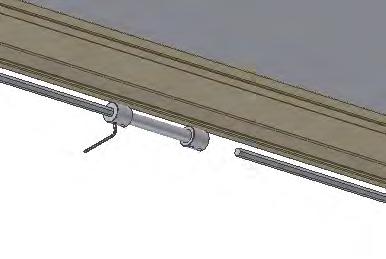
5 5. Supply points, water supply and waste Length of the of the worktop 8 Length of Aluminium bar = Length of worktop minus 5 cm Length of Hex 6 shaft = Length of worktop minus 15 cm It is advisable to place water supply and waste within the hatched area. Also it is important to use flexible hoses for water supply and waste to ensure that the Flexi will move freely without obstacles within the height adjustment range cm. excl. worktop. It is advisable to place the water supply and waste close to the sink. The drain may also be installed in the floor. Arrange for the fixed feed pipes on the wall to be pointing down, at a height of max. 30 cm. This will ensure that the flexible feed pipes will always flex in a neat curve close to the wall without kinking. A 90 degree valve with a 1/2" exposed thread is recommended. The control unit complies with IP32/ll and must always be installed in accordance with the national Heavy Current Regulations or corresponding international or national standards. The cables to the control unit must be able to move freely during height adjustment of the Flexi. For worktops with cut-outs the distance from either side of the worktop should be considered as shown on the illustration. Always keep 0,5 cm space all away around the worktop Page 5

6 5.1 Tips og tricks Tension in upper bolts of Flexi frames Calculation has been done for ONE leg, which will be worst case. Worktop 62 cm deep. 62 cm 150 Kg Max. Permissible load at the Flexi frame is 150 Kg, evenly distributed. In this example we have put the max. Load in the front of the worktop. 150 x 62 Tension upper bolts: 35 x 2 = 133 Kg/bolt 35 cm Upper mounting holes (2pcs./leg) Safety factor must be used: Safety factor Kg/bolt Safety factor Kg/bolt Safety factor Kg/bolt Under normal circumstances the load will be distributed to the two legs (4 bolts) Determine the difference between a MANUEL and Electric Flexi Leg. Flexi leg seen from the front: By looking thru the small hole, you will face following colour combinations: Black shall always be seen to the right hand side! Red / black Elektric Flexi Leg with fast spindles Green / black Manuel Flexi Leg with slow spindles Green / black Manuel Flexi Leg, which might be retrofitted to an Flexi electric, running with a slow. This is very important information to make a visual verification of the exact Flexi model. Page 6


7 6. Mounting instructions, illustrations The equipment should always be assembled by competent personnel. Prior to assembly check that all parts have been provided. See list of components, from page 21. See also mounting instructions page 14 to ,5 cm cm Page 7


8 8 cm ,5 cm m Page 8


9 Page 9


10 cm L= Worktop length L= Worktop length L= Worktop length 40 cm Lower concealment panel 40 cm Lower cover concealment panel in case of supporting feet 3 cm 8 cm Distance between feet 8 cm Page 10


11 6. Mounting instructions, illustrations converting into electrical ,5 cm 18, Placement of waste pipe Page 11


12 6. Mounting instructions, illustrations converting into electrical Control Box must be mounted on Underside of worktop Mains cable Safety stop connection See & Motor cable M1 Cable for control switch Motor cable M Control Box Safety strip Ø A B Long cable for upward movement (Yellow) C E Short cable for downward movement (Red) Page 12

13 6. Mounting instructions, accessories Page 13
14 6. Mounting instructions, descriptions The equipment should always be assembled by competent personnel. Prior to assembly check that all parts have been provided. See list of components, from page 21. See also mounting drawings from page Assembly of frame Place the aluminium profile on the floor. * If supporting feet have been ordered, first see mounting of feet, item Insert the transmission with fasteners into the groove of the aluminium profile and pass the spindle through the transmission (do not secure) Fit a stop ring and a washer on the spindle on either side of the transmission (do not secure). The washer should be at the end Push the legs into the groove of the lower side of the aluminium profile, one leg from either side Position the adjustable legs on the aluminium profile. If there are any socket outlets obstructing the legs, move the leg a little towards the middle. For frames with two legs, place one leg on either side. For frames with three legs, place the third leg at the middle of the aluminium profile. Secure each leg to the aluminium profile with two bolts. To obtain the correct height (65-95 cm without worktop) simply mount and adjust the threaded bolt to each leg according to fig Note: If the sink or hotplate is placed at the middle of the worktop, move the third leg if any, to the right or left to ensure that the leg and support arm are fitted in the immediate vicinity of the sink, hotplate etc. 6.2 Mounting the support arms on the frame Note: Prior to mounting of the support arms it is important to know the location of the sink and hotplate in relation to the support arms and the handle rod. Where you have an adjustable leg always position a support arm directly over it. Do not adjust the tilting of the arm supports that are positioned on top of the legs (see 6.8). Position the transmission box for the winding handle spindle at the required position before mounting the support arms from either side The support arms may be pushed into the aluminium profile from either side to the required position and fastened with two screws on each support. We recommend a maximum distance between the support arms of 60 cm in order to obtain optimum stability To prevent the spindle from working its way out of the frame during use, push the two stop rings and spacers of the spindle towards each leg and fasten. Page 14
15 6.3 Mounting the frame on the wall Place the frame against the wall and align it. Adjust the two threaded bolts under the legs to ensure that the frame is horizontal To obtain the correct height (65-95 cm without worktop) adjust the threaded bolt to each leg. After mounting, the threaded bolts can be removed. Mark and drill the holes for fastening. Fasten the frame to the wall by means of screws and raw plugs suiting the material of the wall Misalignments up to 0,45 cm on the wall may be adjusted by fitting the provided spacers (0,15 cm) between the legs and the wall. Loosen the legs a bit and slide the spacers in between the wall and the legs, as required, at the top or bottom depending on whether the wall is vertical. 6.4 Mounting of fittings for front fascia Fittings for mounting of the wooden front fascia are provided, corresponding to the number of support arms. Place the front fascia fittings on the side of the support arm and fasten them loosely by means of the screw provided On the outermost support arms we recommend pointing the front fascia fittings towards the middle of the frame to prevent them from conflicting with the side fascia. 6.5 Mounting the worktop Place the tabletop on the frame. The maximum permissible distance from the back of the tabletop to the wall is 0.5 cm. (safety issue) If the frame is moved away from the wall, the distance from the back of tabletop to the wall MUST still be equal to or less than 0.5 cm The standard aluminium profile is 5 cm shorter than the worktop, resulting in a 2.5 cm projection on either side Fasten the worktop with screws through the holes of the support arms. 6.6 Mounting the wooden front fascia Fasten the wooden front fascia at the required position under the worktop by means of a clamp. Press the front fascia fittings forward against the wooden front fascia and fasten with screws from the inside By screwing the front fascia fittings into the worktop you pull the front fascia upward. Finally tighten the screws on the side of the support arm. 6.7 Mounting the side fascia Furniture fittings are provided with the frame to keep the wooden side fascia up against the worktop. Page 15
16 6.8 Adjusting the worktop/ support arms After placing the worktop on the frame you may have to compensate for the weight of the worktop if the frame is no longer horizontal from the wall to the front fascia By means of the two lower screws of each support arm the tilting may be adjusted. Start by loosening the two screws fastening the support arm to the aluminium profile and adjust the two lower screws to make the worktop horizontal. Finally retighten the two upper screws. Repeat this procedure for the support arms in the middle. Do not adjust the support arms placed directly above the legs. 6.9 Mounting the handle When the worktop and front fascia are in place the transmission spindle may be mounted. First drill a 20 mm dia. hole in the wooden front fascia where you want the handle. Place the chrome bush for the handle rod in this hole Insert the assembled spindle into the transmission Loosen one of the M4-screws of the stop ring and pull the transmission spindle out to the required position in relation to the front fascia. Retighten the screw Pull the spindle suspension fitting forward so that it may be fitted under the worktop and fasten it with screws. Push the small stop ring forward against the fitting and tighten the M4-screw Finally fit the handle. When the frame has been assembled, tighten all screws securely. It is very important that the screws fastening the legs and support arms to the aluminium profile are tightened securely Mounting the supporting feet * Option Remove the adjusting screw of the leg Fit the foot and the extension to the leg with the screws provided and tighten the screws Mounting the covers for the legs * Option Press the covers, consisting of an inside and an outside cover, carefully over the leg Lift up the upper/outside cover and press the snap lock into the hole of the leg. It is important to pull the snap lock completely out prior to mounting. Now press in the snap lock to lock it. Page 16
17 6.12 Mounting the concealment panels * Option: Fittings for mounting the concealment panels (panels not supplied by Ropox) For three-legged frames use two sets of fittings Inside/lower concealment panels: Fasten the Z-fittings to the wall in the middle between the legs. Fit Velcro on the Z-fittings and the concealment panels. Also fit Velcro on the legs and the concealment panels. The concealment panels may now be fitted. Outside/upper cover plate: Fit the two angular fittings on the inside of the outside/upper concealment panel. Now fit the angular fittings on the bottom side of the worktop Dimension sketch outside/upper concealment panel. The length is identical with the length of the worktop. The height must be 45 cm Dimension sketch inside/lower concealment panel. The length is identical with the length of the worktop. The height must be 40 cm Inside/lower concealment panel (in case of supporting feet). The length is identical with the length of the worktop. The height must be 40 cm. Cut-out for feet must be 8 cm wide and 3 cm high. The cut-outs of the cover plate must suit the position of the supporting feet Conversion from a manual to a electric version * Option Cut the spindle into two parts. Loosen the stop rings on each side of the spindles. Then push the spindles away from each other Remove the bolts for fastening the transmission, and remove the transmission from the spindle For worktop length cm one motor is mounted. For mounting of motors return to 6.13 Together with the mounting bracket there is a nut, which fits into the grove at the bottom edge of the aluminium profile. When you start tightening the bolt, the nut will turn and interlock in the groove For worktop length cm two motors are mounted. For mounting of motors return to Together with the mounting bracket there is a nut, which fits into the grove at the bottom edge of the aluminium profile. When you start tightening the bolt, the nut will turn and interlock in the groove Slide the connecting bush onto the spindle, and push the two spindle parts together inside the connection. Fasten the four bolts. Page 17
18 6.14 Mounting the flexible water connections and waste hoses Arrange for the fixed feed pipes on the wall to be pointing down, at a height of max. 30 cm. This will ensure that the flexible feed pipes will always flex in a neat curve close to the wall without kinking. A 90 degree valve with a 1/2" exposed thread is recommended When connecting hot and cold water as well as waste hoses ALWAYS use flexible hoses to enable the frame to move freely within the height adjustment range (65-95 cm). The flexible hoses should be fitted so that they may move in an arch parallel with the wall, but without getting squeezed. The length of the hoses must suit the fastening and the travel of the frame. We recommend that water seal and waste pipe be directed backwards towards the wall in order to obtain optimum space under the table and the sink Mounting the control unit Warning ALWAYS switch off mains voltage during assembly Check national regulations to determine the correct location of the control unit Fasten the control unit under the worktop as far to the back as possible. The control unit may be placed anywhere in the longitudinal direction Mount all cable connections as illustrated. The Y-cable is provided with two short-circuit plugs. When mounting the safety stop see section Place the loose cables in the cable bearers and fit the bearers in the grooves of the aluminium profile Mounting the operating unit * If the frame is manually operated, this item does not apply The control switch for the height adjustment must be fitted in the wooden front fascia. It consists of a control switch with a 200 cm long cable provided with a DIN plug for the control switch. Choose the required position in the front fascia and drill an 18 mm dia. hole in the fascia. Push the cable through the hole in the front fascia from the front. The control switch has double-adhesive tape on the back. Remove the protective paper and fit the control switch on the wooden front fascia. Fit the DIN plug of the cable on the control switch. After fitting the socket, fasten the cable under the worktop with the cable bearer so that it does not sag. Relieve the cable on the inside of the wooden front fascia in the immediate vicinity of the control switch. Page 18
19 6.17 Mounting the safety strip under the worktop * Option: Ropox always recommends the use of safety strips for electrically operated frames. Be careful not to bend or damage the safety strip during transport or mounting. Be careful when mounting the safety strip, bending or twisting can reflect on the performance of the safety strip. The surface to which the safety strip is to be attached must be clean, dry and degreased to obtain optimum adhesion. Please refer to safety strip mounting guide Mount the safety strip on the bottom side of the wooden front fascia by means of the double-adhesive tape. Remove the protective paper of the tape and press on the safety strip. Be aware of minimum bending radius (2 cm inside) Pull out the red short circuit plug (E) of the short cable (A) (marked with red). Connect the plug at the end of the safety strip (D) in the available short cable (A) (marked with red). Insert the male plug of the extension cord into the first safety stop (right side of the frame). In the case of more safety stops, connect them in series and end the series by inserting the remaining short-circuit plug into the available male plug of the last safety stop Mounting the press pad for disabled persons * Option * If the frame is manually operated, this item does not apply The press pad for height adjustment must be placed in the wooden front fascia. It consists of a press pad contact and a 150 cm long cable provided with a DIN-plug. The press pad and the cable are delivered as one unit ready for mounting. Drill holes as illustrated to suit the required position Fit the press pad by pulling the cable through the large hole and fasten it in the small holes by means of the M6 nuts provided After fitting the press pad, fasten the cable under the worktop with cable bearers so that it does not sag. Finally fit the DIN-plug in the control unit Mounting of distance plates (1cm) for skirting board * Option In case of skirting boards, you can use the 1 cm deep distance plate to pack the frame out from the wall. Page 19
20 7. Performance test 7.1 Performance test, manually operated frame After installation and prior to use all functions of Flexi must be tested. The test must be carried out by competent personnel. Subsequently the test shall be carried out at least once a year: 1. Check that the mounting instructions have been observed. 2. Check that all bolts have been tightened. 3. There must be no load on the frame. 4. There must be nothing preventing the frame from moving freely within the height adjustment range (65-95 cm). 5. Turn the handle, move the frame to bottom position and check that the movement is smooth and even. Make sure that the hoses follow the movement of the frame and do not get squeezed. 6. Now turn the handle and move the frame to top position and check that the movement is smooth and even. Make sure that the hoses follow the movement of the frame and do not get squeezed. If all these tests are ok, the Flexi is ready for use. 7.2 Performance test, electrically operated frame After installation and prior to use all functions of Flexi must be tested. The test must be carried out by competent personnel. Subsequently the test shall be carried out at least once a year: Testing prior to connection of mains voltage: 1. Check that the mounting instructions have been observed. 2. Check that all bolts have been tightened. 3. Check that all cables have been connected correctly and that the plugs have been pressed home. 4. Check that there is no load on the Flexi frame. 5. Check that there is nothing preventing the Flexi from moving freely within the height adjustment range. Now connect mains voltage to the control unit and proceed as follows: 6. Press DOWN on the control switch, move the Flexi frame to bottom position and check that the movement is even and smooth. Make sure that the hose connections follow the movement of the Flexi frame and that they do not get squeezed. 7. Press DOWN on the control switch and keep the switch depressed for approx. 5 sec. or until a click is heard from the control unit. The Flexi frame may move a bit further downward and will now have been reset. 8. Press UP on the control switch, move the Flexi frame to top position and check that the movement is even and smooth. Make sure that the hose connections follow the movement of the Flexi frame and that they do not get squeezed. If a safety strip has been mounted under the Flexi frame it must be tested as follows: 9. Press DOWN on the control switch and let the Flexi frame move 2-5 cm downward. Now activate the safety strip by pressing it lightly. The frame must stop the downward movement, move 1-2 cm upward and stop. If a safety strip has been fitted above the frame, e.g. on a wall cupboard Diagonal, this must also be tested as follows: 10. Make sure that the Flexi frame is in the bottom position. Press UP on the button and let the frame move 2-5 cm upward. Now the safety strip above the Flexi frame will be activated. The Flexi frame must now stop its UPWARD movement and move 1-2 cm downward and stop. If all these tests are ok, the Flexi frame is ready for use. Se section 10 Safety in use. Page 20
 3 pcs.")
21 8. List of components for KitFrame Flexi for worktop cm Legs, standard height cm : Length of worktop = cm Length of worktop = cm 2 legs 3 legs The legs comprise: Spacers (0.15 cm) 3 pcs./leg For misalignment Distance plates (1 cm) 2 pcs/leg For skirting board Cable bearer /leg Support arm for worktop cm : Length of worktop = cm Length of worktop = cm Length of worktop = cm Length of worktop = cm Aluminium profile 30-68xxx: Length (XXX) = Worktop length 5cm At increments of 5 cm The profile comprises: 30-69xxx Spindle Length (xxx) = Worktop length -15cm At increments of 5 cm 2 pcs. 4 pcs. 5 pcs. 7 pcs. Handle incl. transmission : Depth of worktop = cm The handle comprises: Mounting parts: Stop ring 2 pcs Washer ø15/ø8 2 pcs Furniture fittings 4 pcs Fascia serrel Page 21
22 9. Options for KitFrame Flexi Support arm for worktop depth cm : Length of worktop = cm Length of worktop = cm Length of worktop = cm Length of worktop = cm Support arm for worktop depth cm : Length of worktop = cm Length of worktop = cm Length of worktop = cm Length of worktop = cm Support arm for worktop depth cm : Length of worktop = cm Length of worktop = cm Length of worktop = cm Length of worktop = cm Distance plate (1 cm) : For skirting board Distance bracket (7 cm) : For void behind the frame Cover : Length of worktop = cm Length of worktop = cm Cover for supporting foot : Length of worktop = cm Length of worktop = cm Cover, Stainless steel : Length of worktop = cm Length of worktop = cm Cover for supporting foot, Stainless steel : Length of worktop = cm Length of worktop = cm Fittings for concealment panels : 2 pcs. 4 pcs. 5 pcs. 7 pcs. 2 pcs. 4 pcs. 5 pcs. 7 pcs. 2 pcs. 4 pcs. 5 pcs. 7 pcs. 2 pcs. 3 pcs. 2 pcs. 3 pcs. 2 pcs. 3 pcs. 2 pcs. 3 pcs. 1 set Supporting foot, L = 30 cm : Length of worktop = cm Length of worktop = cm Supporting foot L = 49 cm : Length of worktop = cm Length of worktop = cm Each foot comprises: 2 pcs. 3 pcs. 2 pcs. 3 pcs. 30* Leg extension for foot Page 22
 and fitting 30-67851: Control unit, Slow speed(22x11x7 cm): 1 set for 1 motor 240VAC Incl.")
23 Electrical kit 1 for Flexi cm : : Motor (16x8x8 cm): Motor vertical Incl. motor cable (200 cm) and fitting : Control unit, Slow speed(22x11x7 cm): 1 set for 1 motor 240VAC Incl. mains cable (300 cm) The control unit comprises: Y-cable Plug w/ resistor 2 pcs Extension cord for safety stop 250 cm (black) Control switch (2,5x5 cm) : Incl. 150 cm cable Mounting parts : Stop ring 2 pcs Washer ø15/ø8 2 pcs Furniture fittings 4 pcs : Connecting bush: Electrical kit 2 for Flexi cm : : Motor (16x8x8 cm): Motor vertical 2 pcs. Incl. motor cable (200 cm) and fitting : Control unit, Slow speed (22x11x7 cm): 1 set for 2 motors 240VAC Incl. mains cable (300 cm) Parts supplied as on page 23 Same parts as above. Press pad (14x7 cm) : For disabled people, incl. 150 cm cable Infrared control, : Range cm The infrared control is supplied with: : Split cable Safety strip 30-69XXX: Length X in whole cm British standard 3-pin plug : with 200 cm cable Page 23
24 Smartbox : Option for safety stop Flexi, (when two Flexi frames are situated side by side). Coupling Diagonal and Flexi : Option for safety stop plate Diagonal (40900) To be ordered together with safety stop The coupling comprises: Extension cord (250 cm) Extension cord : For safety stop, 250 cm (black) Spiral extension : For safety stop, cm (black) 10. Safety in use The Flexi frame should only be used by people, who have read and understood these instructions. Flexi is a height-adjustable frame and should not be used as a lifting table or person lifter. On electrically height-adjustable Flexi frames we recommend the fitting of safety stop rails in order to guard against and avoid injury and accidents. Nevertheless, always make sure that there are no people, animals or objects under the Flexi frame during height adjustment. Always use the Flexi frame so there is no risk of damage to people or property. The person, who operates the Flexi frame, is responsible for avoiding damage or injury. If the Flexi frame is used in publicly accessible locations where children or people with reduced observation ability may get close to the Flexi frame, the person operating the Flexi frame must pay sufficient attention in order to prevent dangerous situations. Make sure that there is free space above and below the Flexi frame to allow height adjustment. Do not overload the Flexi frame and make sure that the load distribution is correct. Do not operate the Flexi frame in case of errors or damage. Do not use the Flexi frame in an explosive environment. Any modification of the Flexi frame, which may influence its operation or construction, is forbidden. Installation, service and repairs must be carried out by competent personnel. In case of inspections, service or repairs make sure that the Flexi frame is not loaded. If the Flexi frame has not been installed in accordance with these mounting instructions, the guarantee may become void. Only use Ropox original spare parts as replacement parts. If other spare parts are used, the guarantee may become void. Page 24
25 11 Cleaning and maintenance 11.1 Cleaning The frame may get dirty during use. It is very important to clean the frame as described in these instructions. The frame must not be connected to the mains voltage during cleaning. Do not flush electrical components with water. Clean the frame with a damp cloth using lukewarm water and ordinary cleaning agents. Do not use Corrosive/ abrasive liquids or abrasive cloths, brushes or sponges. After cleaning dry the frame Maintenance The frame is maintenance-free and the moving parts have been lubricated for life. For reasons of safety and reliability we recommend inspection of the frame once a year. Inspections, service and repairs must be carried out by competent personnel During inspections: Check that all bolts have been tightened. Check that the frame moves freely from bottom to top position without problems. Resetting the frame: Press DOWN on the control switch and move the frame to bottom position. Press DOWN once more and keep the switch depressed for 5 sec. to reset the control unit. Check that the movement is even and smooth. Make sure that the mains cable moves freely. Check that water and waste pipes are tight and undamaged. Check that all cables have been fitted correctly and are undamaged. After each inspection the service schedule shall be filled in. See item Only use Ropox original spare parts as replacement parts. If other parts are used, the guarantee may become void. Page 25
26 11.3 Service schedule, operation and maintenance Service and maintenance Serial No.: Date: Sign: Remarks: Service and maintenance Serial No.: Date: Sign: Remarks: Service and maintenance Serial No.: Date: Sign: Remarks: Service and maintenance Serial No.: Date: Sign: Remarks: 12. Trouble shooting 12.1 Manuel operated frames a) The frame seems loose or unstable The screws assembling the frame have not been securely tightened. Tighten all screws, cf. mounting instructions. b) The worktop is not horizontal in relation to the wall After installation of the frame the worktop will be loaded. This deflection may be balanced by repeating item 6.8 Adjusting the Support arms of the mounting instructions. Also check that the legs are vertical see item 6.3. c) The height of the frame cannot be adjusted / adjustment seems very difficult 1. Check that the frame is not overloaded. 2. Check that the frame moves freely and that no objects have been squeezed above or below the worktop. 3. Check that the handle has been fitted correctly in the transmission see mounting instructions. Page 26
27 13. CE-marking Manually adjustable frames: Flexi, manual with 2 legs cm Flexi, manual with 3 legs cm Electrically adjustable frames: Flexi, electrical with 1 motor and 2 legs Flexi, electrical with 2 motors and 2 legs Flexi, electrical with 2 motors and 3 legs cm cm cm conform to the following directives and standards: DIRECTIVES EU-Directive 89/392/EEC on Machinery, modified by Directive No. 98/37/EC 73/23EEC, Low voltage directive, modified by 93/68/EEC 89/336/EEC, EMC-Directive, modified by 92/31/EEC and 93/68/EEC STANDARDS DS/EN ISO : 2003 DS/EN : 2000 DS/EN ISO : 2003 DS/EN : 1997 DS/EN 527-2: 2002 DS/EN : 2002 DS/EN :2001, EN Class B DS/EN :2001, EN :1995, A1:2001 DS/EN :2001, EN , -3, -4, -5, -6, -8, -11. Declarations of Conformity can be supplied upon request. Page 27
28 14. Complaints We refer to our general Terms of sale and delivery on our homepage ROPOX A/S Ringstedgade 221 DK 4700 Naestved Tel.: Fax.: Page 28
Top spin Nr /
 Top spin Nr. 1840 0000 / 1840 1000 Bedienungsanleitung 21-6680 28052014 / A Made in Germany Ideas for dental technology Top spin Nr. 1840 0000 / 1840 1000 Contents 1. Introduction...2 1.1 Symbols...2 2.
Tube Facing Tool.
 www.swagelok.com Tube Facing Tool This manual contains important information for the safe and effective operation of the Swagelok TF72 series tube facing tool. Users should read and understand its contents
SERVICE MANUAL for Telescopic pole, Gripo Alu
 Telescopic pole Gripo Alu Side 1 av 11 HEPRO aid manufacturer HEPRO is a Norwegian industrial company that develops, manufactures and sells technical aids for adults and children with mobility impairment.
Merloni Elettrodomestici. Technical Fitting Manual FRIDGE. Language Issue/Edition Page GB /
 GB 99-11-03/01 1-38 Index 1 CONFORMITY OF APPLIANCE 3 2 MAIN ASSEMBLY TYPES 3 2.1 Under worktop 3 2.2 Double door 10 2.3 Combined 14 2.4 Single door Fridge or single door Freezer 19 2.5 Combined free-standing
UPLIFT 2-Leg Height Adjustable Standing Desk
 UPLIFT -Leg Height Adjustable Standing Desk Also watch our assembly video http://bit.ly/9ywwh DIRECTIONS FOR ASSEMBLY AND USE TABLE OF CONTENTS PAGE Safety and Warnings Usage Parts List Assembly Instructions
S E L E C T I O N. Arm Curl. User manual
 S E L E C T I O N T H E S T R E N G T H E V O L U T I O N User manual The identification plate of the and manufacturer, affixed behind the seat, gives the following details: A Name and address of the manufacturer
Repair manual. Fifth-wheel coupling JSK 38/50
 Repair manual Fifth-wheel coupling JSK 38/5 ZDE 199 3 12 E 6/212 1 Foreword Table of contents Page Fifth wheel couplings are connecting parts that must comply with very high safety requirements and must
aluminium profile system
 aluminium profile system 63 AME System aluminium profiles overview series profiles introduction 80x80 x80 x80/180 x Aluminium profiles are provided with longitudinal grooves which can be used in conjunction
Due to possible damage in shipping, the vertical stop assembly has been removed from this machine.
 Due to possible damage in shipping, the vertical stop assembly has been removed from this machine. To assemble, insert the threaded rod through the shroud opening in the top of the machine. Start the four
Fig. 2 DORMA-Glas Stand/Issue 02/03 Seite/Page 1/7
 FSW Installation instructions Track rail 75 x 72 mm 1. Ceiling substructure and installation of the track rail (Fig. 1): The track rail must be bolted over its entire length (including the stacking track
UPLIFT Height Adjustable Standing Desk 3-Leg (T-Frame) DIRECTIONS FOR ASSEMBLY AND USE
 DIRECTIONS FOR ASSEMBLY AND USE") UPLIFT Height Adjustable Standing Desk 3-Leg (T-Frame) DIRECTIONS FOR ASSEMBLY AND USE CAUTION MAKE SURE NO OBSTACLES ARE IN THE DESK S PATH AND ALL CORDS ARE OF APPROPRIATE LENGTH FOR DESK TRAVEL. FAILURE
UPLIFT Height Adjustable Standing Desk 3-Leg (T-Frame) DIRECTIONS FOR ASSEMBLY AND USE CAUTION MAKE SURE NO OBSTACLES ARE IN THE DESK S PATH AND ALL CORDS ARE OF APPROPRIATE LENGTH FOR DESK TRAVEL. FAILURE
VARIABLE SPEED WOOD LATHE
 MODEL MC1100B VARIABLE SPEED WOOD LATHE INSTRUCTION MANUAL Please read and fully understand the instructions in this manual before operation. Keep this manual safe for future reference. Version: 2015.02.02
- 4 - Fig. 3b. Fig. 1b. Fig. 2. Fig. 2b MT 300
 MP 00 Manual 1 7 6 9 8 5 1 1 10 11 1 Fig. 1a Fig. 1b MT 00 Breite Buche Erle Pappel Balsa 0 0,5 0,8 0,8 0,8 max. Zustellung mm 0 0, 0,6 0,8 0,8 60 0, 0, 0, 0,8 80 0,1 0,1 0, 0,6 n Messerwelle = 6.000/min
Installation Instructions
 For Medium (15-18.5K) + Heavy duty (22-28.5K) Air Conditioner READ BEFORE INSTALLING UNIT To avoid risk of personal injury, property damage, or product damage due to the weight of this device and sharp
OPERATING INSTRUCTIONS
 OPERATING INSTRUCTIONS Rotary Microtome CUT 4062 / CUT 5062 / CUT 6062 CUT 6062 illustrated above INS1000GB 2012-01-06 Instructions CUT4062 / CUT 5062 / CUT 6062 2 CONTENTS 1. INTENDED USE... 4 2. SYMBOLS...
Installation Instructions
 READ BEFORE INSTALLING UNIT INSTALLATION WARNINGS AND CAUTION Carefully read the installation manual before beginning. Follow each step as shown. Observe all local, state, and national electrical codes
HOUSE PARTS PACKED IN HOUSE BOX PARTS IN PLASTIC BAG (HARDWARE) PARTS IN SMALL PLASTIC BAG (FLOOR CLIPS) PARTS PACKED IN BUNDLE
 PARTS IN SMALL PLASTIC BAG (FLOOR CLIPS) PARTS PACKED IN BUNDLE") Check parts against this list before starting assembly. Refer to illustrations on pages 6 and 7 to view house parts. If any shortages are found, refer to Packing Slip for claim instructions. Item 3 5 6
Check parts against this list before starting assembly. Refer to illustrations on pages 6 and 7 to view house parts. If any shortages are found, refer to Packing Slip for claim instructions. Item 3 5 6
READ BEFORE INSTALLING UNIT INSTALLATION WARNINGS AND CAUTION
 edium + Heavy duty READ BEFORE INSTALLING UNIT INSTALLATION WARNINGS AND CAUTION Carefully read the installation manual before beginning. Pay attention to danger and safety notices. be exposed: Carefully
Installation Instructions
 edium + Heavy duty READ BEFORE INSTALLING UNIT Preliminary instructions: 1. Check window opening size: the mounting parts furnished with this air conditioner are made to install in a wooden sill double-hung
Parts list continues on Page 2 HOUSE PARTS PACKED IN HOUSE BOX PARTS IN SMALL PLASTIC BAG (HARDWARE) POST PARTS PACKED IN THIS BOX (LARGE PLASTIC BAG)
 POST PARTS PACKED IN THIS BOX (LARGE PLASTIC BAG)") Form 05-07 Instructions and Parts List MSS- Martin Safety System NOTES: () A complete system is packed in two boxes post box and house box. House box contains hardware for both post and house assembly.
Form 05-07 Instructions and Parts List MSS- Martin Safety System NOTES: () A complete system is packed in two boxes post box and house box. House box contains hardware for both post and house assembly.
OPERATING INSTRUCTIONS 5-AXIS CLAMPING SYSTEM + ACCESSORIES
 OPERATING INSTRUCTIONS 5-AXIS CLAMPING SYSTEM + ACCESSORIES 1 Contents 1. Introduction 2. Safety instructions and precautions 3 Operating the clamp 3.1 Clamp set up 3.2 Sequence for clamp set up 3.3 Adjusting
Side Winder R o u t e r L i f t.
 Woodpeckers PRECISION WOODWORKING TOOLS Side Winder R o u t e r L i f t. INSTALLATION INSTRUCTIONS The wrench handle must be pointing left in order to fully insert or remove it. Lift Wrench Once fully
TUCANA-02 P PORTABLE END MILLING MACHINE USER S MANUAL
 TUCANA-02 P PORTABLE END MILLING MACHINE USER S MANUAL 1 CONTENTS Page 1. General Information 3 1.1. Introduction 3 1.2. Manufacturer 3 2. Machine s Description and Purpose of Use 3 2.1. Machine s description
FLEXRISE2 VERSION. 2 LEG / 2 MOTOR ELECTRIC TABLE BASE (36 to 72 ) **PATENT PENDING**
 **PATENT PENDING**") FLEXRISE2 2 LEG / 2 MOTOR ELECTRIC TABLE BASE (36 to 72 ) VERSION A INSTRUCTION MANUAL CONTENTS: FLEX-MU-2L3S-C3672-K4# FEET-ADJ-UNV-2430# **PATENT PENDING** MAX Load 265 lbs (120 KG) Equally Divided MAX
FLEXRISE2 2 LEG / 2 MOTOR ELECTRIC TABLE BASE (36 to 72 ) VERSION A INSTRUCTION MANUAL CONTENTS: FLEX-MU-2L3S-C3672-K4# FEET-ADJ-UNV-2430# **PATENT PENDING** MAX Load 265 lbs (120 KG) Equally Divided MAX
Installation Instructions
 For Medium (15-18.5K) + Heavy duty (-8.5K) Air Conditioner READ BEFORE INSTALLING UNIT To avoid risk of personal injury, property damage, or product damage due to the weight of this device and sharp edges
S E L E C T I O N. Upper Back. User manual
 and S E L E C T I O N T H E S T R E N G T H E V O L U T I O N User manual and and The identification plate of the and manufacturer, affixed to the frame on the side opposite the padded rest, gives the
UPLIFT 2-Leg Height Adjustable Standing Desk - For use with UPLIFT Eco and Eco Curve desktops -
 UPLIFT -Leg Height Adjustable Standing Desk - For use with UPLIFT Eco and Eco Curve desktops - DIRECTIONS FOR ASSEMBLY AND USE TABLE OF CONTENTS Please Note PAGE Safety and Warnings Usage Parts List Assembly
OPERATIONS MANUAL. Port-O-Slitter
 OPERATIONS MANUAL Port-O-Slitter General instructions, set up, accessories and guide to using your portable precision slitting, rib forming and perforating system Saves hours on large siding jobs! Featuring:
GENERAL OPERATIONAL PRECAUTIONS PRECAUTIONS ON USING CUT-OFF MACHINE
 GENERAL OPERATIONAL PRECAUTIONS WARNING! When using electric tools, basic safety precautions should always be followed to reduce the risk of fire, electric shock and personal injury, including the following.
Hydraulic Clamp Carrier. Installation & Operation Manual
 Hydraulic Clamp Carrier Installation & Operation Manual Hydraulic Clamp Carrier Installation & Operation Manual Quick Machinery Company 8272 Peninsula Drive Kelseyville, CA 95451 phone: (707) 272-6719
Pneumatic Clamp Carrier. Installation & Operation Manual
 Pneumatic Clamp Carrier Installation & Operation Manual Pneumatic Clamp Carrier Installation & Operation Manual Quick Machinery Company 8272 Peninsula Drive Kelseyville, CA 95451 phone: (707) 272-6719
GENERAL OPERATIONAL PRECAUTIONS
 GENERAL OPERATIONAL PRECAUTIONS WARNING! When using electric tools, basic safety precautions should always be followed to reduce the risk of fire, electric shock and personal injury, including the following.
Table and Furniture Base Fittings Plinth Adjusting Fittings
 Adjusting screw with M8 or M thread Rigid, for glide inserts, steel thread Finish/Colour: Black, thread galvanized Version: With acceptance Ø30 mm Thread M8 650.22.381 M 650.22.382 Packing: 1 or 0 pcs.
installation instructions WC Frame 1180mm with Dual Flush Cistern
 installation instructions WC Frame 1180mm with Dual Flush Cistern (C,D,E) K F/G N L M 12 13 14 16 1 2 11 A 5 6 Q O Y 3 C 10 E D B P,Z,AA R T V S 4 U 2 No. Part no. Description Quantity A WC Frame with
 GENERAL OPERATIONAL PRECAUTIONS WARNING! When using electric tools, basic safety precautions should always be followed to reduce the risk of fire, electric shock and personal injury, including the following.
Operating Instructions K-POWERgrip EWL Always on the safe site.
 Operating Instructions K-POWERgrip EWL 4941. Always on the safe site. KaVo Elektrotechnisches Werk GmbH Wangener Straße 78 D-88299 Leutkirch A 1 User information...2 A 1.1 Meaning of the pictograms...2
OPERATIONS MANUAL. Port-O-Slitter
 Tapco Products Company The World Leader in Specialty Tools for the Professional Port-O-Slitter OPERATIONS MANUAL General instructions, set up, accessories and guide to using your portable precision slitting,
FLEXCELL HONEYCOMB BLINDS
 FLEXCELL HONEYCOMB BLINDS GETTING STARTED BRACKET INFORMATION A few simple tools are required: The brackets you received with your product are REQUIRED for proper installation. s should be installed at
Bending Roll Machine 4126
 Bending Roll Machine 4126 Operating Instructions Table of contents Main components...4 Operation...5 Safety...7 Service and maintenance... 12 Machine plates and stickers... 13 Dismantling the bending
FABA. Installation Instructions. Conductor Bar System. Publication #FABA-03 3/1/04 Part Number: Copyright 2004 Electromotive Systems
 FABA Conductor Bar System Installation Instructions Publication #FABA-03 3/1/04 Part Number: 005-1062 Copyright 2004 Electromotive Systems 1S 100 Z Installation Instructions Contents: Basic Diagram - -
18000 HDL FOUR POST LIFT LB CAPACITY INSTALLATION AND OWNER'S MANUAL
 18000 HDL FOUR POST LIFT 18000 LB CAPACITY INSTALLATION AND OWNER'S MANUAL WARNING! Do not raise a vehicle unless the front stops are in place, the parking brake is set, and the wheels are chocked. Stay
HOME GYM Owner s Manual
 HOME GYM Owner s Manual Content Content-------------------------------------------------------------1 Safety precautions----------------------------------------------------2 Assembly instruction-------------------------------------------------3-12
Material Packing Brown Grey Pine Black White
 RTA Connectors Minifix Zinc alloy For housing: 12 or 18 Bolt hole: Ø 7 or 8, depending on choice of connecting bolt Drilling distance B: Distance from centre of Minifix housing to shelf front edge (24
Operating, Servicing, and Safety Manual Model # 100 Standard Hydraulic Tubing Notcher Model #100-U Heavy Duty Hydraulic Tubing Notcher
 Operating, Servicing, and Safety Manual Model # 100 Standard Hydraulic Tubing Notcher Model #100-U Heavy Duty Hydraulic Tubing Notcher Model # 100 Standard Model #100-U Heavy Duty CAUTION: Read and Understand
installation instructions
 installation instructions Easi-Plan WC Frame 820mm with Dual Flush Cistern ref: EPWC-05-1005 Easi-Plan WC Frame 980mm with Dual Flush Cistern ref: EPWC-05-1505 EASI-PLAN installation instructions Parts
Quick Set Dovetail Jig
 Quick Set Dovetail Jig FOR HELP OR ADVISE ON THIS PRODUCT PLEASE CALL OUR CUSTOMER SERVICE HELP LINE : 01509 500359 THE MANUFACTURER RESERVES THE RIGHT TO ALTER THE DESIGN OR SPECIFICATION TO THIS PRODUCT
HD installation guide
 JANUS INTERNATIONAL 1 866 562 2580 www.janusintl.c o m 1950 1950HD installation guide RIGHT DRIVE END SHOWN LH OPPOSITE LEFT TENSION END SHOWN RH OPPOSITE PUSH-UP OPERATION 1950 1950HD SHOWN A rolling
LC200DS1 Double Stud Articulating Wall Mount for Flat Panel Screens up to 32" with up to 200mm x 200mm VESA Mounting Patterns
 Page 1 of 6 LC200DS1 Double Stud Articulating Wall Mount for Flat Panel Screens up to 32" with up to 200mm x 200mm VESA Mounting Patterns A multi-position dual articulating arm for flat screens up to 60
N. 15th Street, Middlesboro, KY FLIP TARP DUMP BODY INSTALLATION INSTRUCTIONS
 1-800-248-7717 1002 N. 15th Street, Middlesboro, KY 40965 FLIP TARP DUMP BODY INSTALLATION INSTRUCTIONS Congratulations on your purchase of a Mountain Flip Tarp Dump Body tarping system. With tarping systems
model tsa-sa48 Sliding Crosscut Table installation guide
 model tsa-sa48 Sliding Crosscut Table installation guide A Note About Color Variations Among Anodized Aluminum Components Congratulations on the purchase of this SawStop Sliding Crosscut Table. We at SawStop
Replacing the Reciprocator on the SWF Compact Series Machine (601C and 1201C)
") Follow the instructions below to replace the reciprocator in the SWF Compact series machines. The tools required can be found in the tool kit that came with the machine. Preparation 1. First, place the
Follow the instructions below to replace the reciprocator in the SWF Compact series machines. The tools required can be found in the tool kit that came with the machine. Preparation 1. First, place the
INS A KSCR INSTALLATION INSTRUCTIONS STANDARD PROCEDURE. 1. Unpacking the KSCR Splicing the KSCR (If Required)...
...") INS-88.500-0A KSCR INSTALLATION INSTRUCTIONS STANDARD PROCEDURE 1. Unpacking the KSCR... 2 2. Splicing the KSCR (If Required)... 4 3. Assemble Curb and Rail Corners... 5 4. Install Cross Bracing (If Required)...
INS-88.500-0A KSCR INSTALLATION INSTRUCTIONS STANDARD PROCEDURE 1. Unpacking the KSCR... 2 2. Splicing the KSCR (If Required)... 4 3. Assemble Curb and Rail Corners... 5 4. Install Cross Bracing (If Required)...
ROBOT KR 350. Installation, Connection, Exchange. Ro/Me/03/ en. 1of 26
 ROBOT KR 350 Installation, Connection, Exchange 1of 26 e Copyright KUKA Roboter GmbH This documentation or excerpts therefrom may not be reproduced or disclosed to third parties without the express permission
Fifth-wheel coupling JSK 38/50
 Repair manual Fifth-wheel coupling JSK 38/5 ZDE 199 3 12 E 6/25 1 LT SK38C-3 English RevA Foreword Table of contents Page Fifth wheel couplings are connecting parts that must comply with very high safety
VARIABLE SPEED WOOD LATHE. Model DB900 INSTRUCTION MANUAL
 VARIABLE SPEED WOOD LATHE Model DB900 INSTRUCTION MANUAL 1007 TABLE OF CONTENTS SECTION...PAGE Technical data.. 1 General safety rules....1-3 Specific safety rules for wood lathe.....3 Electrical information.4
LEG CURL IP-S1315 INSTALLATION INSTRUCTIONS
 LEG CURL IP-S35 INSTALLATION INSTRUCTIONS Copyright 2009. Star Trac by Unisen, Inc. All rights reserved, including those to reproduce this book or parts thereof in any form without first obtaining written
ASSEMBLY AND CARE INSTRUCTIONS JUST FOR KIDS 355
 ASSEMBLY AND CARE INSTRUCTIONS VERSION: 8920100 (Revised 06/16) JUST FOR KIDS 355 SALES AND SERVICE spiethamerica.com Canada and International 135 Forestview Road, PO Box 40 Orillia, Ontario, Canada L3V
MODEL 83 Pail Handler
 MORSE MFG. CO., INC. 727 West Manlius Street P.O. Box 518 East Syracuse, NY 13057-0518 Phone: 315-437-8475 Fax: 315-437-1029 Email: service@morsemfgco.com Website: www.morsemfgco.com COPYRIGHT 2005 MORSE
installation guide
 JANUS INTERNATIONAL 1 866 562 2580 w w w. j a n u s i n t l. c o m 2000 2500 3000 installation guide RIGHT DRIVE END SHOWN LH OPPOSITE LEFT TENSION END SHOWN RH OPPOSITE PUSH-UP OPERATION 2000 2500 3000
SPIDA SAW OPERATIONS MANUAL
 SPIDA SAW OPERATIONS MANUAL CM SERIAL NUMBER. OCTOBER 2000 CONTENTS Page description 1.) Contents 2.) Safety First 3.) CM Overview 4.) CM Specifications 5.) CM Installation 6.) CM Operation Setting the
NEWS Part. N /0 MINITEC NEWS
 NEWS 2009 Part. N 95.0423/0 MINITEC NEWS 2009 1 TABLE OF CONTENT INTRODUCTION CONTENTS 3 END CAP Z WITH HAMMER TAPS 3 END CAP 45X45 VA 4 ANGLE 25 GD-Z 4 ANGLE 45X90 GD-Z 5 ANGLE 90 GD-Z 5 HINGE 19 S 6
Pneumatic Clamp Carrier. Installation & Operation Manual
 Pneumatic Clamp Carrier Installation & Operation Manual Pneumatic Clamp Carrier Installation & Operation Manual Quick Machinery Company 8272 Peninsula Drive Kelseyville, CA 95451 phone: (707) 272-6719
FD 125 Large-Format Card Cutter
 FD 125 Large-Format Card Cutter 3/201 OPERATOR MANUAL Page 2 Table of Contents SAFETY PRECAUTIONS... 4 Introduction... 5 Specifications... 5 Accessories... 5 Major Components and Assemblies... 6 Control
FLIP TARP SINGLE & DOUBLE UNDERBODY TRAILERS
 1-800-248-7717 1002 N. 15th Street, Middlesboro, KY 40965 FLIP TARP SINGLE & DOUBLE UNDERBODY TRAILERS INSTALLATION INSTRUCTIONS Congratulations on your purchase of a Mountain Flip Tarp Trailer system.
MODEL W1.0X305A(12 ) MODEL W1.0X610A(24 ) HAND BENDING BRAKE ASSEMBLY&OPERATING INSTRUCTION
 MODEL W1.0X610A(24 ) HAND BENDING BRAKE ASSEMBLY&OPERATING INSTRUCTION") MODEL W1.0X305A(12 ) MODEL W1.0X610A(24 ) HAND BENDING BRAKE ASSEMBLY&OPERATING INSTRUCTION 1 SAVE THIS MANUAL You will need the manual for the safety warning and precautions, assembly instructions, operating
MODEL W1.0X305A(12 ) MODEL W1.0X610A(24 ) HAND BENDING BRAKE ASSEMBLY&OPERATING INSTRUCTION 1 SAVE THIS MANUAL You will need the manual for the safety warning and precautions, assembly instructions, operating
Rouen Storage Bed. John Lewis PRE-ASSEMBLY PREPARATION. Double King Size. Stock code: 803/44304 Stock code: 803/44305
 John Lewis Double King Size Rouen Storage Bed Stock code: 80/4404 Stock code: 80/4405 Thank you for purchasing this Rouen Storage Bed. Please read the instructions carefully before use to ensure safe and
INSTALLATION AND CARE INSTRUCTIONS
 INSTALLATION AND CARE INSTRUCTIONS Skylight Manually Operated Honeycomb Shades 20 C8-10-1806 2/15 1 INTRODUCTION Thank you for purchasing our product. Your new shade has been custom built for you from
Not including the type of fabric used (clear pvc or shade mesh), there are three main types of side screen.
, there are three main types of side screen.") installation Outrigger side screens are installed as a single stage job when the screens are fitted to a existing structure. However, two stages may be necessary if, for whatever reason, reliable measurements
installation Outrigger side screens are installed as a single stage job when the screens are fitted to a existing structure. However, two stages may be necessary if, for whatever reason, reliable measurements
Depending on the size you ordered you will have either 5 Foot sections which will build the 10 Foot frame or 6 Foot sections which will build the 12
 XL Quilting Frame 1 Depending on the size you ordered you will have either 5 Foot sections which will build the 10 Foot frame or 6 Foot sections which will build the 12 Foot frame Printed 2 June 2014 Updated
Assembly Instructions. Beta Prusa DualX 3D Printer
 Assembly Instructions Beta Prusa DualX 3D Printer Version 2.6 Date Page 1 / 72 General data about the assembly instructions for an incomplete machine according to appendix VI of the EG machinery directive
southpaw enterprises, inc.
 southpaw enterprises, inc. Instruction Sheet C-STAND 7100 Store these instructions in a safe place or with the enclosed maintenance checklist Take time to familiarize yourself with the use and maintenance
Piazzola Pergola Awning Manufacturing and installation guide
 Piazzola Pergola Awning Manufacturing and installation guide Date Changes Page General information Maximum and minimum width Width Projection 150 to 349 cm 350 to 500 cm From 200 to 250 cm X From 251 to
S-85SCH
 4411-4423-4432-4443-4452 5511-5523-5532-5554 44S-85SCH Service Manual 104 73 14-26 2014-02-24 CONTENTS 1. Names of principal parts...2 2. Removing methods of external parts 2-1 Sewing table...3 2-2 Face
Maintenance & Parts list for:
 Maintenance & Parts list for: Industrial gun GB 2 Juni 2017 This Maintenance & Parts list for industrial gun is prepared by : Winchester Europe Service V. Parbst & Søn as a comprehensive maintenance guide
VARIOCLIP MANUAL 29JR
 VARIOCLIP MANUAL 29JR CENTRE SUPPORT Consists of plug in elements with interlocking and safety bolts. Adaptable to any frame size. FOLDABLE LEGS Standard delivery AT32/64. According to the size of the
SERVICE INSTRUCTIONS Model 9670 Lubricant Pump
 TM TM SERVICE INSTRUCTIONS Model 9670 Lubricant Pump 9670 DESCRIPTION Model 9670 Lubricant Pump is designed to pump light to heavy oils directly from the original container. This design features a 10:1
M4 Foot Operated Underpinner Instruction Manual
 M4 Foot Operated Underpinner Instruction Manual M4 Walker Rd, Bardon Hill, Coalville, Leicestershire LE67 1TU, England Tel. +44 (0)130 1692, Fax +44 (0)130 16929 e mail sales@framerscorner.co.uk M4 Underpinner
Type XTSR71 Sizes
 (Page 1 of 13) s 494-5258 Type XTSR71 s 494-5258 Figure 1 Thomas XTSR71 Coupling 1. General Information 1.1 Thomas Couplings are designed to provide a mechanical connection between the rotating shafts
MSR/MSB Mechanical Setting Tool
 Tech Unit No: 0620000004 Revision: B Approved By: Quality Engineer Date: 2014-12-16 MSR/MSB Mechanical Setting Tool FEATURES: Special designed Bow Spring provides positive control and allows one size Mechanical
KD Table Base Assembly and Top Attachment Instructions
 KD Table Base Assembly and Top Attachment Instructions 4011xx 5000xx 7014xx 8001xx 8206xx Congratulations on the purchase of your Tropitone furniture. Read through all steps before starting assembly. CAUTION:
GENERAL OPERATIONAL PRECAUTIONS PRECAUTIONS ON USING DISC GRINDER
 GENERAL OPERATIONAL PRECAUTIONS WARNING! When using electric tools, basic safety precautions should always be followed to reduce the risk of fire, electric shock and personal injury, including the following.
Sales & Service. JFK - Just For Kids. sasportonline.com. 135 Forestview Road 7879 Will Rogers Blvd.
 Sales & Service sasportonline.com SA Sport (Canada) SA Sport (U.S.A.) 135 Forestview Road 7879 Will Rogers Blvd. P.O. Box 40 Fort Worth, Texas Orillia, Ontario USA 76140 Canada L3V 6H9 Telephone: (705)
TherAdapt Products Inc. (800) phone (866) fax
 phone (866) fax") TherAdapt Products Inc. (800) 261-4919 phone (866) 892-2478 fax www.theradapt.com Feeding Chair- 2-in-1 Booster Seat Please read all of the following information before using this product. TherAdapt Products
TherAdapt Products Inc. (800) 261-4919 phone (866) 892-2478 fax www.theradapt.com Feeding Chair- 2-in-1 Booster Seat Please read all of the following information before using this product. TherAdapt Products
imove-f Assembly Manual (Motorized Version-M1/M2)
") imove-f Assembly Manual (Motorized Version-M1/M2) 2 Table of Contents Exploded Desk Diagram Hardward & Tools Section 1: Basic Assembly of Desk Shipped KD (knock down) 3 4 5 Section 2: Attaching the Lowboard/Pedestal
imove-f Assembly Manual (Motorized Version-M1/M2) 2 Table of Contents Exploded Desk Diagram Hardward & Tools Section 1: Basic Assembly of Desk Shipped KD (knock down) 3 4 5 Section 2: Attaching the Lowboard/Pedestal
Cut-Off Machine Model CC 14SE
 Cut-Off Machine Model CC 14SE Handling instructions NOTE: Before using this Electric Power Tool, carefully read through these HANDLING INSTRUCTIONS to ensure efficient, safe operation. It is recommended
TherAdapt Products Inc. (800) phone (866) fax
 phone (866) fax") TherAdapt Products Inc. (800) 261-4919 phone (866) 892-2478 fax www.theradapt.com Posture Chair Please read all of the following information before using this product. TherAdapt Products Inc. has designed
TherAdapt Products Inc. (800) 261-4919 phone (866) 892-2478 fax www.theradapt.com Posture Chair Please read all of the following information before using this product. TherAdapt Products Inc. has designed
ELEGANCE SHOWER DOOR/ENCLOSURE INSTALLATION INSTRUCTIONS. Style A Style B Style C Style D
 ELEGANCE SHOWER DOOR/ENCLOSURE INSTALLATION INSTRUCTIONS IMPORTANT DreamLine reserves the right to alter, modify or redesign products at any time without prior notice. For the latest up-to-date technical
TITGEMEYER Tf1673GB(0517)1. GETO City Body Kit with a self-supporting base and without a base Assembly Instructions
1. GETO City Body Kit with a self-supporting base and without a base Assembly Instructions") TITGEMEYER Tf1673GB(0517)1 with a self-supporting base and without a base All rights reserved. The technical data quoted in this catalogue, performance descrip - tions, recommendations and instructions
TITGEMEYER Tf1673GB(0517)1 with a self-supporting base and without a base All rights reserved. The technical data quoted in this catalogue, performance descrip - tions, recommendations and instructions
INSTALLATION MANUAL GIOTTO SCREEN
 INSTALLATION MANUAL GIOTTO SCREEN Before installing the Giotto screen, please read the following instructions carefully: The Giotto screen must be used INDOORS ONLY. It is forbidden to stay under the Giotto
7. Operating instructions: EFL 300
 7. Operating instructions: EFL 300 Copyright 2015 by Endecotts Ltd. 59 1. Setting up Technical specifications SIEVE SHAKER MODEL: EFL 300 General Information The new EFL 300 combines the best features
S6 User s Manual USER S MANUAL ver. 1.0
 S6 User s Manual SKEETER - 1U LOW PROFILE SOLUTION Table of Contents Tabletop Configuration 2 Tabletop Configuration Accessories 4 Slide Configuration 5 slide configuration accessories 7 rack Mount configuration
Bathroom Installation Guide
 Bathroom Installation Guide Please read instructions carefully and check products before starting. Products should be fitted/installed by an experienced and competent fitter, failure to do so may invalidate
MM540 Installation Instructions IMPORTANT SAFETY INSTRUCTIONS - SAVE THESE INSTRUCTIONS
 MM50 Installation Instructions IMPORTANT SAFETY INSTRUCTIONS - SAVE THESE INSTRUCTIONS Please read this entire manual before you begin. Do not unpack any contents until you verify all requirements on PAGE.
ATD AMP Variable Speed Reciprocating Saw Owner s Manual
 ATD-10535 7 AMP Variable Speed Reciprocating Saw Owner s Manual Manufactured in China To ATD Tools, Inc. Specifications TECHNICAL SPECIFICATIONS Voltage: 120V Frequency: 60Hz Power input: 7 Amps No load
Star Trac Turbo Trainer Assembly & Setup
 Star Trac Turbo Trainer Use the following procedures to unpack and assemble your Turbo Trainer manufactured by Star Trac. UNPACKING AND PARTS LIST Position the shipping carton so the Heavy End logo is
INS A KSR INSTALLATION INSTRUCTIONS STANDARD PROCEDURE. 1. Verify Curb Installation Required Installation Tools...
 INS-88.300-0A KSR INSTALLATION INSTRUCTIONS STANDARD PROCEDURE 1. Verify Curb Installation... 2 2. Required Installation Tools... 2 3. Unpacking the KSR... 3 4. Attach KSR Bottom Rail to Curb... 5 5. Attach
Owner s Manual #TSGUARD
 Owner s Manual #TSGUARD PSI Table Saw Dust Collection Guard The ideal solution for table saw dust control. Version 3, 02/04 2004 PSI Woodworking Products 9900 Global Rd., Philadelphia, PA 19115 WARRANTY
TB & SB Series Drill Presses
 TB & SB Series Drill Presses OWNERS MANUAL BENCH AND FLOOR DRILL PRESS TB-16 Series & SB-16-25-32-Series FOR YOUR OWN SAFETY AND OPTIMUM OPERATION READ INSTRUCTION MANUAL BEFORE OPERATING DRILL PRESS RETAIN
Assembly Instructions
 InTandem Table System November 20 InTandem Table System - Worksurface #4 x/" 4 wood screw power beam Tools Provided T-0 Extended Torx Driver T-25 Torx Driver Additional Tools Required Soft protective
Assembly Instructions for model: VMPR1
 Assembly Instructions for model: VMPR1 Congratulations on your purchase! The VMPR1 ceiling mount provides a unique, simplified method of ceiling mounting inverted LCD/DLP projectors. Its low profile design