breathing walls Installation instructions
|
|
|
- Rosamund Wilson
- 5 years ago
- Views:
Transcription


1 breathing walls Installation instructions Environmentally friendly

2
3 Content 1 Application possibilities for ventilating facades Advantages of ventilated facades Division of 6 2 Types of TEMPSI boards for 2.1 TEMPSI Base 2.2 TEMPSI Colore 2.3 TEMPSI Profilo 2.4 TEMPSI Granito Basic properties of cement-bonded particleboards of type 8 3 Machining and storing of boards Machining of facade-boards Packaging and storing of facade-boards 9 4 CLADDING facade system CLADDING facade system Scheme of laying of TEMPSI boards in the VARIO system Mounting instructions 11 5 PANNELLO facade system PANNELLO facade system Scheme of laying of TEMPSI boards in the PANNELLO system 14 6 Composition of facade system Bearing structure Thermal insulation Air gap Bearing grid from wood Bearing grid from aluminum/zinc coated metal profiles Auxiliary material Mounting of wooden bearing structure of the facade 20.2 Mounting of aluminum/zinc coated metal bearing structure for TEMPSI facade 20.3 Mounting of TEMPSI facade boards 21.4 Solution of details at TEMPSI 21 3
4 4
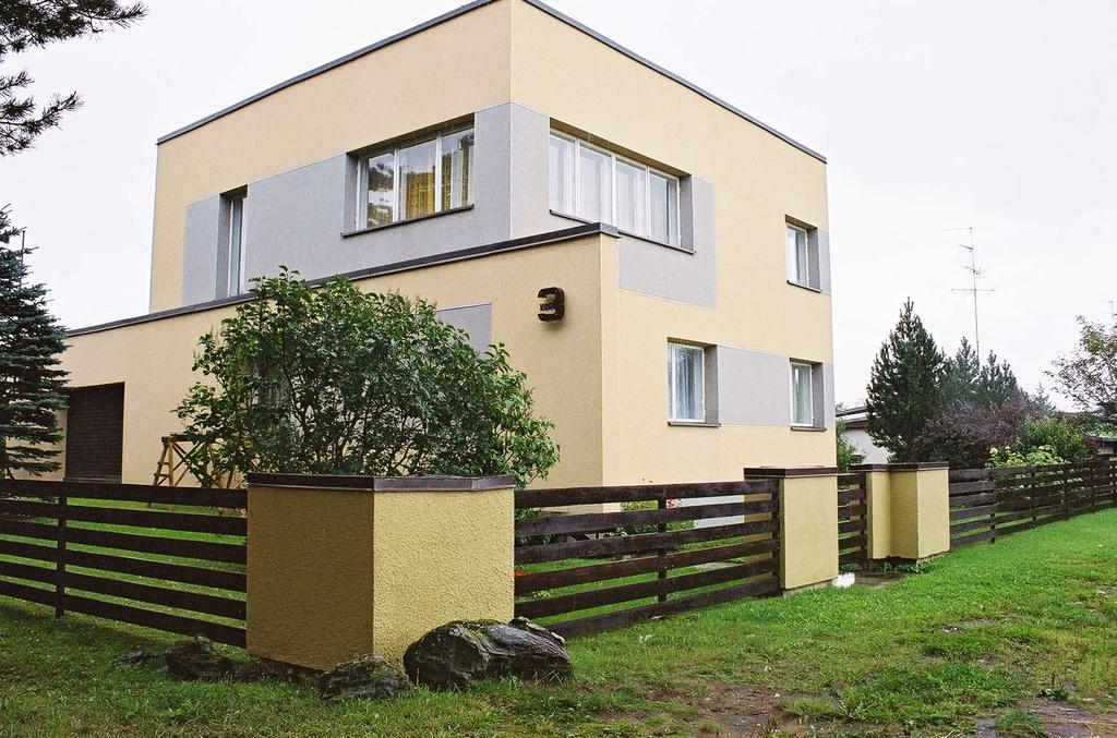
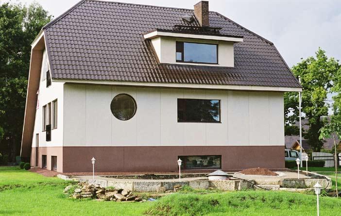
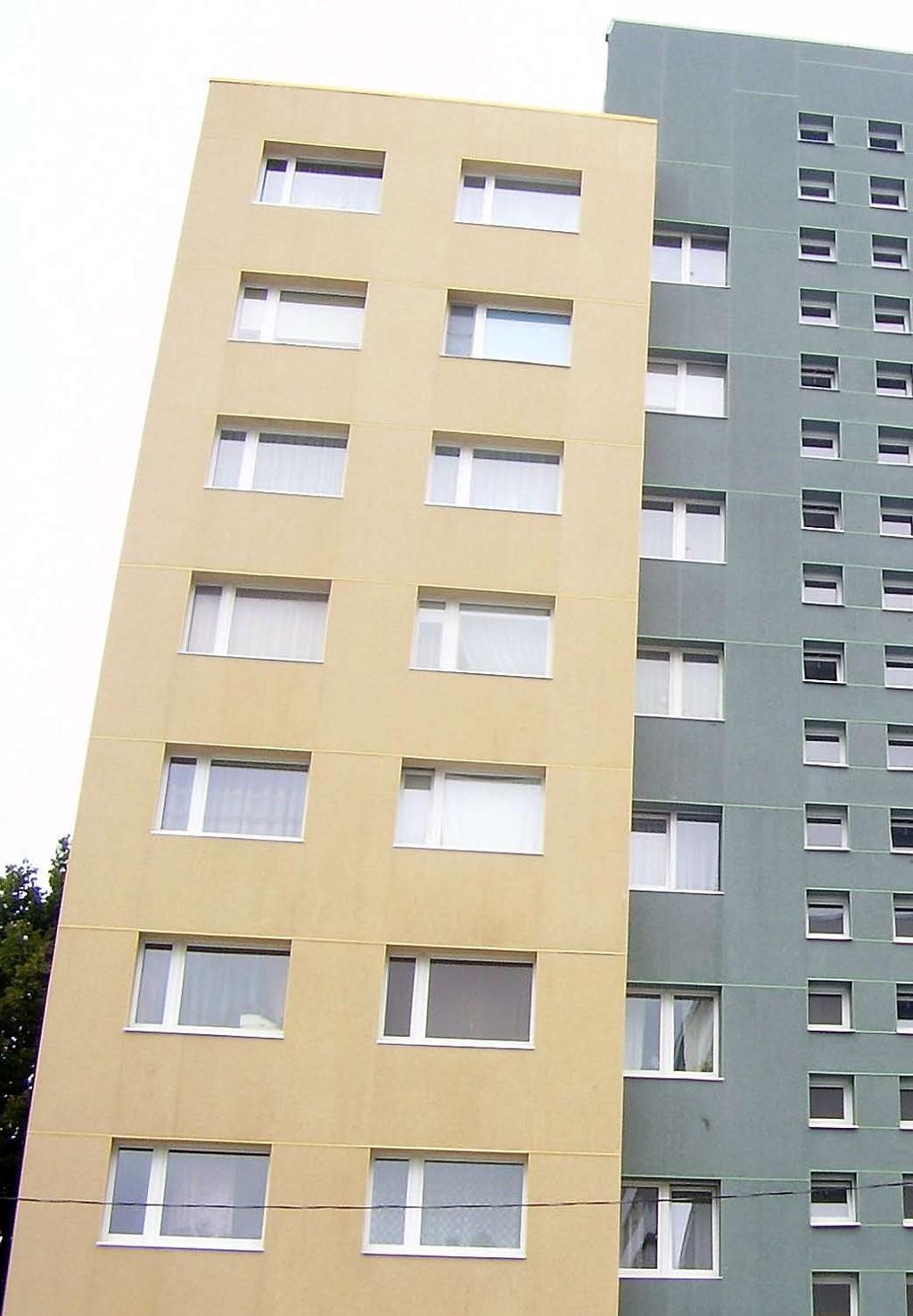
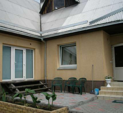
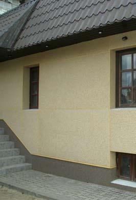
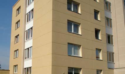
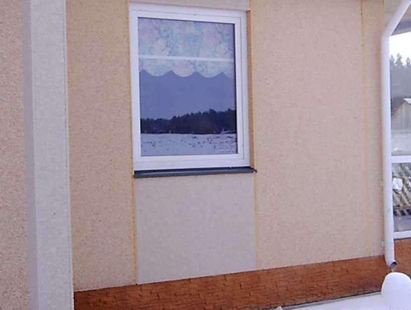
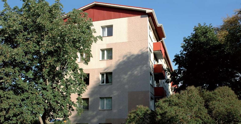
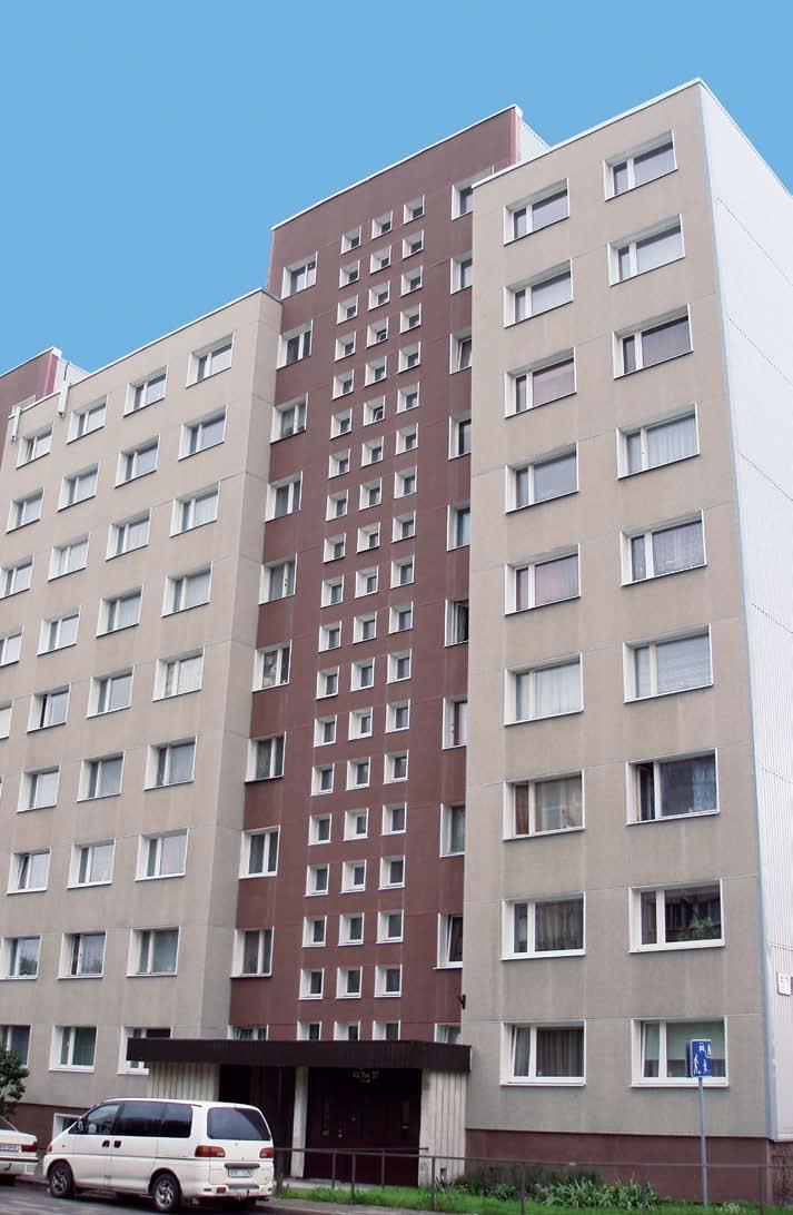
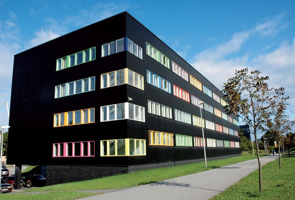
5 Application possibilities for ventilating facades 1 Besides improved thermal insulation properties, protection of walling against moisture, noise damping and a better esthetic aspect of buildings is accentuated in these days. The relative moisture content in internal heated housing and office rooms is about 60 %. Moisture is pressed towards the outer wall surface, where water vapor condenses. When the escape of water vapor is hindered by, for instance, a ceramic coating, vapor accumulates in walling. The thermal conductivity of walling increases and water in walling freezes in winter and the volume of frozen walling increases and damages the plaster. Also, in such a way moulds can form in the interior. An optimal solution of such problems is the application of ventilating. 1 Application possibilities for ventilating facades The ventilated facade system from can be used both for new buildings and for reconstruction of family houses, flat buildings, office buildings, civic amenities, industrial and agricultural buildings. The functional and elegant ventilated facade from boards fulfils the requirements to high quality, esthetic, functionality and lifetime. The ventilated facade system can be completed with thermal insulation. Description of the facade system: The ventilated facade is an integral part of peripheral structure and therefor the structure has to be treated as an unit from static point of view, and in case of additional thermal insulation also from thermal conductivity point of view. The bearing structure ensures the insertion of thermal insulation and the fastening of facade lining to the bearing wall of the building Thermal insulation a layer of thermal insulating material, fastened to the outer surface of peripheral structure of the building Facade cover protects the bearing structure and the thermal insulation against the influence of weather and creates an esthetic aspect of the building at the same time 1.1 Advantages of ventilated facades Thermal insulation in winter the optimal choice of thermal insulation thickness in connection with the ventilated air ensures the minimal consumption of energy for heating of the house Thermal insulation in summer the thermal damping of the facade decreases the overheating of the interior caused by the solar radiation in the summer Hinged facade the hinged facade effectively protects before direct influence of the weather and holds the thermal insulation and wall in a perfect dry condition Diffusion of water vapor the ventilated facade has favorable influence to the diffusion of water vapor in the structure and enables this way the achieving of an optimal moisture regime both in the wall and in the thermal insulation, and enables the drying of wall eventually. The stack effect between the internal cover and the thermal insulation ensures the perpetual removal of water vapor Acoustic insulation the thermal insulation from mineral fiber provides also an acoustic insulation and dominantly contributes to the protection against the outer noise Facade cover a facade element from boards is an element of many possible combinations of sizes, shapes, surfaces and colors and contributes to perfect realization of the architectural requirements to the facade The system eliminates the eventual unevenness of existing wall thermal load resistance against moisture thermal resistance diffusion of water vapor Easy replacement of individual facade elements The structure is built using a dry method of mounting, so the works can be performed the whole year ventilated facade system applied on bearing decreased thermal expansion fire resistance acoustic insulation structure is a system, which together with the existing bearing structure creates a new peripheral structure, fully fulfilling all requirements to function, thermal properties, static, architectonic aspect at achieving a satisfactory lifetime. 5
 Depending on the location of boards on the facade we divide the as follows: A1) CLADDING")
 Two types of bearing grids can be used for anchoring of boards on the facade B1) wooden bearing")


6 1 Application possibilities for ventilating facades 1.2 Division of A) Depending on the location of boards on the facade we divide the as follows: A1) CLADDING facade system a facade system with manifested horizontal and vertical joint between the individual facade elements B) Two types of bearing grids can be used for anchoring of boards on the facade B1) wooden bearing grid The extent of use of the ventilated facade system on a wooden is limited with the fire-fighting regulations. The extent of use of the ventilated facade system on aluminum, zinc coated profiles is not limited with firefighting regulations. boards have a reaction to fire class A 2-s1, d0 according to EN standard. A2) PANNELLO facade system a facade system with overlapped horizontal (the vertical joint is manifested only) joints B2) bearing grid from system profiles from aluminum, zinc coated sheets 6
.")


7 Types of TEMPSI boards for TEMPSI Base The TEMPSI Base is a cement-bonded particleboard with a smooth surface (with relief) and its basic version is of cement gray color. It is suitable to provide this board with final colored or transparent paint (when the original cement aspect is required). The surface treatment increases the protection of board against weather influences and prolongs its lifetime. TEMPSI Base has a wide range of use either for renovation of old structures or for building of new structures as floor, ceiling, walls, roof element, also in structures which have extra requirements for fire safety and resistances against environment effects. At designing of from TEMPSI Base boards without surface treatment the composition of the board material cement ware has to be taken into account. The elements of free (not bonded) lime contained in the Portland-cement could penetrate up to the board surface and carbonize on the air by causing white flowers, which could disturb the uniform aspect of the board surface. Claims due to such reasons therefore cannot be accepted. This phenomenon could be partly prevented by treatment of the board with deep penetrating paints, which decrease the absorbing capacity and hinder the transport of mineral substances on the board surface. 2.2 TEMPSI Colore The TEMPSI Colore is a cement-bonded particleboard with smooth surface provided with a ground painting and a final painting (with environment effects resistant acrylic or polyurethane paints) in color shades of RAL, NCS color charts. The main area of its use are facades of old and new private houses, apartment houses, commercial and industry buildings, and their architectural details: socles, balconies, sound barriers. TEMPSI Colore might also serve for interior walls decoration purposes because of their mechanical resistances and a broad chart of colours, and in structures which have extra requirements for fire safety and resistances against environment effects as well. 2.3 TEMPSI Profilo The TEMPSI Profilo is a cement-bonded particleboard (of 10 or 12 mm thickness), the surface of which is composed from embossment imitating the structure of wood, plaster or slate. The board surface is provided with a ground painting and a final painting (with environment effects resistant acrylic or polyurethane paints) in color shades of RAL, NCS color charts. The main area of its use are facades of old and new private houses, apartment houses, commercial and industry buildings and their architectural details: socles, balconies, sound barriers. TEMPSI Profilo might also serve for interior walls decoration purposes because of their mechanical resistances and broad chart of colours and in structures which have extra requirements for fire safety and resistances against environment effects as well.


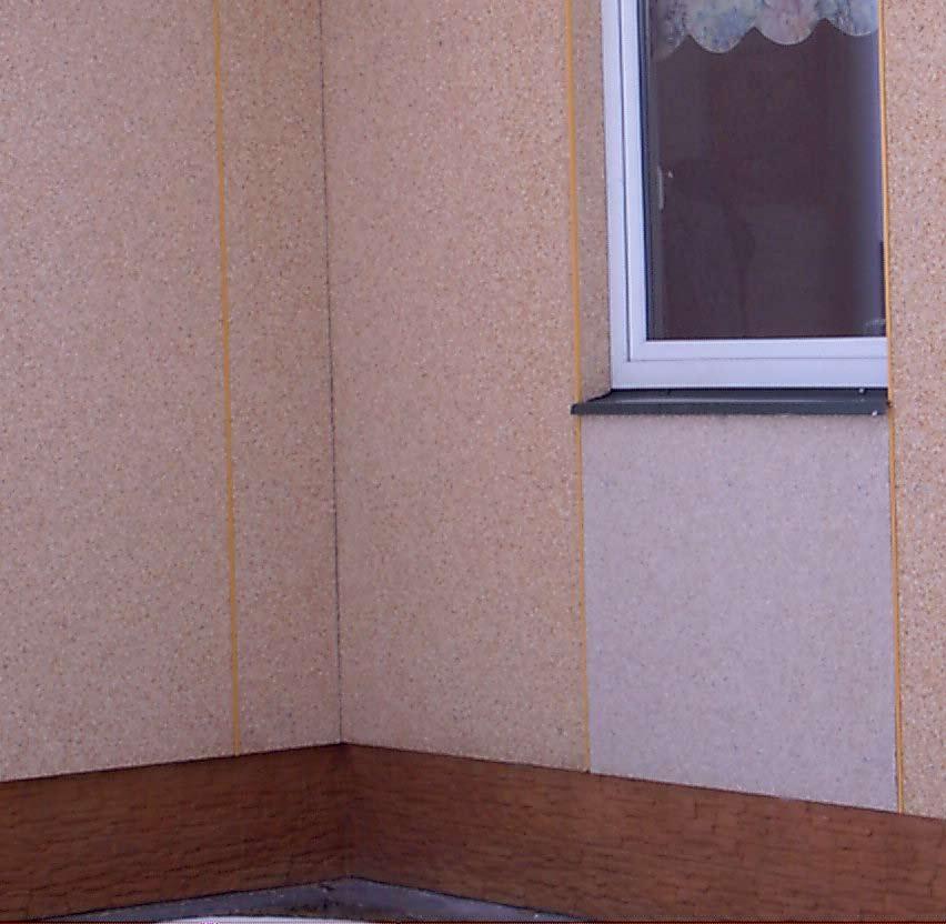
8 2 Types of TEMPSI boards for 2.4 TEMPSI Granito The TEMPSI Granito is a cement-bonded particleboard, the surface of which is strewn with marble gravel of three different granularity and in 12 colors according to color chart. The main area of its use are facades of old and new private houses, apartment houses, commercial and industry buildings and their architectural details: socles, balconies, sound barriers. TEMPSI Granito might also serve for interior walls decoration purposes because of their mechanical resistances, also as a good choice for buildings with extra requirements for fire safety or resistances to environment effects. 21 R, White 33 R, Natural grey 35 R, Black graphite 34 R, Red granite 85 R, Yellow dolomite 10 R, Natural brown 84 R, Green 83 R, Pink 88 R, Rosso Verona 13 R, Canterbury 94 R, Beige 8 R, Verde Alpi 2.5 Basic properties of cement-bonded particleboards of type The table of principal physical-mechanical properties of cement-bonded particleboard of type Density kg/m³ Tensile strength at bending min. 9.0 Nmm² Modulus of elasticity according min Nmm² Tensile strength perpendicularly to board plane min. 0.5 Nmm² Equilibrium moisture at 20 C and at 50 % relative humidity 9 ± 3 % Linear extensibility at change of air relative humidity from 35 % to 85 % at 23 C max % Coefficient of thermal expansion (according to VUPS methodology) 0.1 mm/m C Water absorption after 24 hour immersion in water max. 16 % Thickness swelling after 24 hour immersion in water max. 1.5 % Combustibility grade A non-flammable Resistance against high voltage and low intensity arc discharge according to EN standard min. 143 sec for thick. 10 mm Coefficient of heat conductivity (according to EN standard) max W/mK thickn. 8 mm 30 db Soundproof level thickn. 24 mm 33 db thickn. 40 mm 35 db Water vapor diffusion 0.239x10⁻¹¹ s Radioactivity < 30 Bq/kg Jointing after cycling in humid environment min. 0.3 MPa Thickness swelling in humid environment max. 1.5 % Frost resistance at 100 cycles R L > 0. 8
9 Machining and storing of boards Machining of facade-boards The cement-bonded particleboards can be easily cut with a circular saw with carbide tipped cutting tools. A guiding lath should be used to achieve a clear and direct cut and the cutting should be provided from the backside in order not to damage the front side. The pre-boring of holes should be done with a boring machine without impact, on a solid base. A drill for metal is recommended. The boring should be done from the front side only. Machining of facade-boards with surface treatment Boring Cutting Surface treatment Surface treatment 3.2 Packaging and storing of facade-boards The cement-bonded particleboards are delivered on wooden transport pallets, packaged into protective foil. boards are separated by a softened foil that prevents damage of boards during transportation. The boards have to be stored and packaged on a solid and stable base in a dry environment, protected against rain and dust. 9
10 4 CLADDING facade system 4.1 CLADDING facade system The recommended thickness for cement-bonded particleboards for is 10 and 12 mm. For coating of pedestals boards of greater thickness can be delivered. boards for with manifested joint of type CLADDING can be delivered in maximal dimensions of 1250 x 3350 mm. The boards Prop distances and screw spacing can be delivered also in other dimensions; the minimal size for a facade board is 300 x 300 mm. The boring of holes and the span of consoles should correspond to the technological prescriptions. The method of fastening to the bearing structure has to enable the displacement caused with volume changes of facade boards. The individual facade elements should be fastened with joint min. 5 mm at board maximal side up to 1600 mm and min. 10 mm at the maximal dimension of 3350 mm. When the holes are bored on site, the hole diameter in the CLADDING system has to be 1.5 time bigger than the screw diameter. BOARD THICKNESS (mm) SCREW/BOLT SPACING b (mm) PROP DISTANCE a (mm) 8 <400 < <450 < <500 < <550 < <550 <00 *Applicable for the boards applied lengthwise (width > 1,85 mm) DISTANCE BETWEEN THE SCREW AND THE VERTICAL EDGE c 1 (mm) wood zinc coated* aluminum >30 <50 >30 <50 >50 <0* DISTANCE BETWEEN THE SCREW AND THE HORIZONTAL EDGE wood zinc coated* aluminum c 2 (mm) >50 <0 >0 <100 Pre-drilling the boards: It is advisable to pre-drill holes for screws with hole diameter 1.5 times the diameter of the used screw To provide for stability, a minimum of one fixed point (of 5 mm) is required. Spacing between the boards should be 5 10 mm. Screw type: SFS S Hole diameter 1.5 times wider than screw diameter c 1 c c 2 SFS S c Scheme of laying boards in CLADDING facade system min min. 50 Exposed location, edges, passage edges e = 1.5 m min. 5 LEGEND: 1 TEMPSI cement-bonded particle board 2 vertical supports 3 screws for fastening of TEMPSI boards 4 joints between TEMPSI boards min. 5 min. 5 EXPOSED LOCATION e=1.5 m EDGES, PASSAGE EDGES USUAL LOCATION all dimensions in mm 10
11 CLADDING facade system Mounting instructions Two independent L profiles in the joint Due to high thermal dilatability, the aluminum/zinc coated metal profile roster is made only from L profiles, i.e. the boards vertically touch by means of two independent L profiles. When mounting a zinc coated profile roster, use T profiles to attach the TEMPSI boards with width 1,65 mm. If the boards are wider (applied lengthwise), proceed as when mounting the aluminum/zinc coated metal understructure, i.e. use two independent L profiles instead of the T profile. Maximum aluminum and zinc coated profile roster length is 3,35 m. The dilation between the profiles is always located along the horizontal gap, minimum width 10 mm. The bearing roster (attaching the anchors and their spacing, anchoring the profiles fixed and moveable points, etc.) must be assembled as per the instructions provided by the roster supplier. All connecting material used for an aluminum roster must be made of stainless steel. Maximum length of roster from wooden laths is 6 m. The wooden components must be thoroughly dry and treated against dampness, insects and woodworm. When using a combined roster, put every other anchor on the other side of the wooden laths (to reduce deformation). Dilation between the laths is always located along the horizontal gap, minimum width 10 mm. Using stainless steel anchoring material is recommended. NEVER attach a board to two different rosters (different materials or different dilation units)! L profile (aluminium) L profile (aluminium) L profile (zinc, length over 1,65 mm) max. 1,65 mm L profile (zinc) T profile (zinc) 11


12 4 CLADDING facade system Correct way of mounting the L-profiles along the vertical gap Prop distance exceeded Inappropriate anchoring of the TEMPSI boards (profile and screw spacing maximum values exceeded) causes deformation (bulging or bending) which may lead to damage breaking the boards! Base under the Boards not leveled When using auxiliary profiles (in corners, filling the gap), level the base along the whole height of the profile. Dilation aluminium or zinc coated roster Dilation wooden roster Correct use of the rubber tape Put an EPT rubber tape on the profiles under the TEMPSI boards to level the base and facilitate dilation. The tape prevents the temperature spreading through the construction as well as potential corrosion leaking into the bottom layers (zinc coated roster). min. 10 mm 10 mm 10 mm max mm 10 mm 10 mm max mm min. 10 mm max mm Faulty Roster Dilation Incorrect profile dilatation, off the horizontal gap level between the boards. 12
.")
 into the centre of the predrilled hole, perpendicular to the board. To ensure for moveable points when using bolts, use a spacer size approx. 1 mm.")
13 CLADDING facade system 4 Please observe the appropriate spacing of the predrilled holes and the connecting material. When anchoring, attach the board in the fixed point first (FEST, one or two points according to the board shape and size as near the board centre as possible). Then attach the sliding moveable points, preferably clockwise. Set the screw tightening moment to prevent the screw or TEMPSI board spacer from deformation. Place the screw (bolt) into the centre of the predrilled hole, perpendicular to the board. To ensure for moveable points when using bolts, use a spacer size approx. 1 mm. Anchoring process Moveable point Moveable point 6.3 mm/4.2 mm Fixed point 4.3 mm Fixed point End Screw too near
14 5 PANNELLO facade system 5.1 PANNELLO facade system The cement-bonded particleboards for the overlapped facade system PANNELLO can be delivered from 200 to 500 mm width, in maximal length 3350 mm. The boring of holes and the span of consoles should correspond to the technological prescriptions. The method of fastening to the bearing structure has to enable the displacement caused with volume changes of facade boards. The individual facade elements should be fastened with joint min. 5 mm at board maximal side up to 1600 mm and min. 10 mm at the maximal dimension of 3350 mm. When the holes are bored on site, the hole diameter in the PANNELLO system has to be 1.2 times the screw shaft diameter. Distance prop and spacing screws BOARD THICK- NESS (mm) SCREW/ BOLT SPACING b (mm) PROP DISTANCE a (mm) 8 <400 < <450 < <350 < <500 < <500 <00 DISTANCE BETWEEN THE SCREW AND THE VERTICAL EDGE c 1 (mm) wood zinc coated* aluminum DISTANCE BETWEEN THE SCREW AND THE HORIZONTAL EDGE wood zinc coated* aluminum c 2 (mm) >35 <50 40 Maximum board length is 3 times the distance/spacing i.e = 1,85 mm for a 12 mm thick board. Pre-drilling the boards: 1.2 times the screw cross-section (usually 6 mm) (Also applies to screws up to 5 mm) Spacing between the boards 5 10 mm b Cement 5 10 Screw type: c 1 c 1 c 2 50 a 5.2 Scheme of laying boards in PANNELLO facade system Two independent L profiles in the joint or two wooden grids min min. 5 EXPOSED LOCATION e=1.5 m EDGES, PASSAGE EDGES USUAL LOCATION 14


15 Composition of facade system Bearing structure 6.2 Thermal insulation The bearing structure has to fulfill all requirements of technical regulations for this type of the structure. Namely homogeneity, compactness, the total and local strength and flatness are important. The strength of the base is determined also according to the requirements of individual producers of anchoring elements and their instructions for designing of given anchoring elements. 6.3 Air gap We recommend, in cases, when a thermal insulation is required, the use of hydrophobic mineral wool with flammability class at least B, with minimal board thickness given with the production program of individual producers and with the requirements to thermal resistance of insulation layer (with calculation of thermal losses). The fastening of insulation boards is provided with plated dowels, in dowel lengths according the instructions of the producer. The minimal quantity of dowels to 1 m² is determined with the instructions of the mineral board producers. The air gap ensures the removal of atmospheric moisture and rain and snowfall moisture through joints into the open system as well as the removal of moisture diffused from the bearing structure. This air gap favorably contributes as inhibition of temperature increase in the bearing structure in the summer. The condensation of moisture in the ventilated area depends namely from the intensity of ventilating air stream and from its velocity. The minimal thickness of the air gap is 25 mm, the maximal 50 mm. 6.4 Bearing grid from wood Bearing structure The bearing structure is composed from a grid of wooden lathes and planks. The lathes and planks are produced from high quality pine timber, dried to a max. 12% moisture content. In such a way dried wood should be impregnated with appropriate fungicide agent. The primary horizontal grid This grid is used, when an additional thermal insulation is required. The grid thickness corresponds with the insulation thickness the recommended width is 100 mm. The dimensions, the method of anchoring, and the lath span are determined by the designer according to the provided static and thermal calculations of peripheral walling. The secondary vertical grid This grid creates the ventilating gap between the facade lining and it forms the bearing structure for the facade boards at the same time. The lath thickness depends on the span of the primary grid and the minimal profile for the ventilating gap minimal cross-section 250 cm²/m and the maximal one 500 cm²/m has to be observed at the same time. This means that the minimal distance of facade-board internal surface from the thermal insulation or to the bearing wall of the building is 25 mm and the maximal one 50 mm. The lathes are fastened to the primary grid in spans corresponding to the facade lining type. The lath width in connection place of two facade elements is min. 100 mm, the interlacing lathes have a 50 mm width. 15

16 6 Composition of facade system 6.5 Bearing grid from aluminum/zinc coated metal profiles Bearing structure The bearing structure is composed from a system of anchors, profiles and consoles. The cost-effective, from static point of view optimized structure of basic system elements enables the composition thickness of the lining from 80 mm to 330 mm. Bearing elements enable thanks to tongue and groove connection with vertical bearing profiles the aligning of unevenness of base structures up to 35 mm in the plane upright to the basic reference plane. The elements of aluminum/zinc coated metal system The elements of aluminum/zinc coated metal system Type CLADDING 1 bearing anchor with dowel and screw 2 vertical T-shaped console 3 self-drilling stainless screws 4 thermal insulation from mineral hydrophobized boards 5 TEMPSI cement-bonded particleboard 6 stainless screw 210 mm anchor 80 mm anchor 290 mm The elements of aluminum/zinc coated metal system Type PANNELLO Bearing anchor with dowel and screw The bearing anchoring element is produced from aluminum or zinc-coated metal, L-shaped, with dimensions of 80/ mm, sheet thickness 2 mm. 1 bearing anchor with dowel and screw 2 vertical L-shaped console 3 self-drilling stainless screws 4 thermal insulation from mineral hydrophobized boards 5 TEMPSI cement-bonded particleboard 6 horizontal console stainless screw Vertical T, L-shaped (corner) consoles The vertical T, L-shaped (also corner) consoles are produced from aluminum or zinc-coated metal, in length of 6000 mm, sheet thickness 1.6 mm. L-shaped profile in dimensions 60/40 mm T-shaped profile in dimensions 60/80 mm Corner profile in dimensions 30/30 mm Self-drilling screws 4.2 The self-drilling screws 4.2 are produced from noble steel of class A4 (resistant against stain, inoxidable). They are used for connection of the anchors with vertical consoles and to connection of customer-built profiles with vertical consoles according to the requirements of the design. The elements of aluminum/zinc coated metal system TYPE ELEMENT 1 bearing anchor with dowel and screw 2 vertical T-shaped console 3 aluminum fasteners for fastening of TEMPSI boards 4 self-drilling stainless screws 5 thermal insulation from mineral hydrophobized boards 6 cement-bonded particleboard 16
 stainless screws with a cylindrical or hexagon")
 galvanized screws with sunk head are used.")
17 Composition of facade system Auxiliary material Screws for fastening of cement-bonded particleboards to the grid For fastening of boards in the system CLADDING (visible joints) stainless screws with a cylindrical or hexagon head with pressing watertight washer are used. The lower side of such washer is provided with vulcanized layer of EPDM elastomer, which ensures the watertight and elastic connection of materials. The type of the screw also depends on the type of the base material the used bearing grid. For fastening of boards in the system PANNELLO (overlapped system) galvanized screws with sunk head are used. The recommended screws for boards of 10 (12) mm in thickness, at wooden bearing structure: noble steel screws, diameter 4.2 mm, length 35 System for invisible fastening (gluing) of boards to the grid The boards can be glued to the grid, when invisible fastening elements (valid for CLADDING system only) are required. The recommended system comes from the company SIKA and is composed from the following components: primer paint (de-greasing agent) SikaTack Panel Primer (for treatment of contact surfaces) double-faced adhesive mounting belt SikaTack (ensures the pressing of board to the grid up to the activation of the glue) gluing mastic (cement) SikaTack Panel When designing this system a consultation with the producer SIKA is necessary. The mounting can be provided Gluing of boards in SIKA system 1 bearing anchor with dowel and screw 2 vertical T-shaped console 3 self-drilling stainless screws 4 thermal insulation from mineral hydrophobized boards 5 TEMPSI cement-bonded particleboard 6 double-faced adhesive belt special gluing mastic with a schooled company only. Permanently elastic connecting sealant (mastic) At laying of cement-bonded particleboards in the PANNELLO system is suitable to secure the free ends of facade boards with application of permanently elastic cements. The acrylic type cements with tensile strength min. 0.1 MPa are recommended for this purpose. Anchoring elements Stainless or galvanized screws are used for fastening of vertical lathes to the horizontal ones (secondary and primary grid). Auxiliary profiles (lathes) to he facade system Special shaped profiles (lathes) are used for solution of details of hinged ventilated facade (lower ending ventilation, upper ending ventilation, lining of holes, outer corners, inner corners, etc.). Such lathes are made from zinc coated sheets (possible colored versions) or from aluminum sheets. The recommended screws for boards board thickness 10 (12) mm, wooden bearing structure: SFS TW-S-D12-A x 38 mm (half-eye) EJOT SAPHIR JT 2-2H 4.9 x 35 mm (hexagonal) EJOT SAPHIR JT 3 -FR x 35 mm (half-eye) The recommended screws for boards board thickness 10 (12) mm, aluminum/ bearing structure (aluminum): SFS SX 3/10-S x 28 mm (hexagonal) EJOT SAPHIR JT x 32 mm (hexagonal) EJOT SAPHIR JT 3 FR 3H 5.5 x 25 mm (half-eye) 1
18 Cross-section of TEMPSI CLADDING facade system with thermal insulation on wooden structure Legend of anchoring elements: 4 A) Fastening of horizontal profiles to the house wall: concrete wall frame dowel, c = 50 mm porous concrete frame dowel, c = 600 mm brick wall frame dowel span c = 600 mm A 5 B) Fastening of thermal insulation layer: dish shaped dowels (according to the type and thickness ofinsulation) according to instructions of insulation material producer, the bearing capacity of the base have to be checked with tests, namely at porous concrete B C C) Fastening of vertical lathes to the horizontal profiles: stainless or galvanized screws 6.3x80 HOUSE CORNER 6 LEGEND: 1 horizontal wooden profiles, (w. h) min thickness of thermal insulation in mm 2 vertical wooden lathes mm 3 vertical wooden lathes mm 4 bearing base structure 5 thermal insulation 6 TEMPSI cement-bonded particleboard EXPOSED LOCATION e=1.5 m EDGES, PASSAGE EDGES USUAL LOCATION all dimensions in mm 18
19 Cross-section of TEMPSI PANNELLO facade system with thermal insulation on wooden structure Legend of anchoring elements: 4 A) Fastening of horizontal profiles to the house wall: concrete wall - frame dowel, c = 50 mm porous concrete - frame dowel, c = 600 mm brick wall frame dowel span c = 600 mm A B C B) Fastening of thermal insulation layer: dish shaped dowels (according to the type and thickness of insulation) according to instructions of insulation material producer, the bearing capacity of the base have to be checked with tests, namely at porous concrete C) Fastening of vertical lathes to the horizontal profiles: stainless or galvanized screws HOUSE CORNER 6 LEGEND: 1 horizontal wooden profiles, (w. h) min thickness of thermal insulation in mm 2 vertical wooden lathes mm 3 vertical wooden lathes mm 4 bearing base structure 5 thermal insulation 6 TEMPSI cement-bonded particleboard EXPOSED LOCATION e=1.5 m EDGES, PASSAGE EDGES USUAL LOCATION all dimensions in mm 19
20 .1 Mounting of wooden bearing structure of the facade Determination of principal axes and reference plane for providing of walls It is suitable to determinate the principal axes, namely the width of pillars between the windows and the reference planes for compact surfaces of the facade lining, when possible. Wooden bearing structure of ventilated facade: Providing of primary grid horizontal lathes The wooden lathes are with wall plugs (dowels) fastened to the aligned base in order to achieve a bearing structure of a corresponding stability. The wall plug type and size is chosen considering the properties of the base. At uneven base the lathes are aligned with wooden rests. For aligning of individual surfaces we should fasten the vertical lathes on their sides. We drive nails in these lathes and extend lines between them. The face plane of the wooden grid is determined by this method. We adapt also other horizontal laths by inserting wooden rests or locking into the wall to this plane. Then the lathes should be fastened. Mounting of thermal insulation layer We fasten the horizontal lathes to the base first, when additional thermal insulation is provided (the lath thickness is the same as for insulation). We insert lengthwise the thermal insulation, fastened with dish-shaped wall plugs to the base. The mounting of thermal insulation layer with dish-shaped wall plugs should be provided according to requirements of the producer of anchoring elements. The quantity of dish-shaped wall plugs is determined by the designer according to recommendation of the producer of thermal insulation. The thermal insulation layer has to be fit tightly to the base, continuously, without open joints (very tightly!). The dishshaped wall plugs should have a solid bed in the base and they should fit tightly to the insulation layer. Providing of secondary grid vertical bearing lathes The vertical lathes (with minimal width 50 mm, in connection of two lathes 100 mm) are fastened with screws to the primary grid. The span of lathes should not be greater as the determined value. After fastening of vertical lathes an air gap will be created in the grid, the minimal width of this air gap is 25 mm, the maximal one 50 mm. Mounting of auxiliary structures The auxiliary structures are fastened according to requirements of realization documentation. They are namely auxiliary vertical or horizontal lathes determine the openings (window and door case and rabbet), internal and external corners, lower and upper endings, etc..2 Mounting of aluminum/zinc coated metal bearing structure for TEMPSI facade The bearing structure can be provided with a company schooled by the producer only. The mounting is composed from the following partial steps: determination of the principal axis and the reference plane measurement of the raw building, determination of the axis of vertical consoles mounting of bearing elements mounting of vertical bearing lathes mounting of auxiliary structures mounting of TEMPSI cement-bonded particleboards details of opening s case and rabbet, corners, arch dilatations, etc. boring and cutting of TEMPSI cement-bonded particleboards contact of facade lining with transient structures Measurement (survey) of principal axis and reference plane for providing of the brickwork It is suitable to determinate the principal axes, namely the width of pillars between the windows and the reference planes for compact surfaces of the facade lining, when possible. Keeping of such principal dimensions and the evenness according to the reference plane in case of the walls as the base for the bearing structure of aluminum/zinc coated metal could spare all additional expenditures connected with modification of dimensions and evenness of facade lining base or with modification of the thickness of facade lining and distribution of joints, eventually. We mark with help of a laser beam, taking into account the segmentation of facade lining the reference vertical axis, with reference to which we measure the first right or left side axis, or the axis of symmetry for the surface, eventually. From the solid axis determined in such a way we measure the edges for pillars between the windows, in the highest and lowest level of the surface. The edges of such pillars are determined for prevention of an eventual measurement error, with help of a measure tape with integral method of measuring. We mark the reference plane with help of a laser beam in a distance about 100 mm from the assumed wall front. In such a way the net of axis is created that determines the bearing structure for the facade lining (wall) on the whole surface and also in place of openings, both in regard of their size and heir location. The survey of finished raw building We provide this step as in the previous part: We determine the vertical axis. We determine the vertical axis of vertical elements of the cover (lining) from this principal axis. With repeated measurement we check, if the location of window pillows, infillings or openings for such infillings corresponds to the corresponding documentation for the facade lining. It is necessary to adjust the above mentioned dimensions providing additional building, cutting with the documentation, in case of deviations. It is prohibited in order to ensure the corresponding strength of the base to provide the above mentioned modifications with lime-cast or lime-cement cast or with screening. We drive nails or rod from concrete reinforcing so they should run out about 150 mm from the base. We mark with help of a laser beam in a distance of about 100 mm from wall front, the reference plane, which we mark further on auxiliary points (nails, rods). We measure the distance between the reference axis and the front of the base, e.g. we ensure the planeness of the walling. We insert in the place of minimal distance between the front of the base and reference axis an anchor and then with self-drilling screws we fasten to it the vertical bearing profile such a way, that it will be in a minimal possible distance from the front of the base (up to contact). Thus, the maximal distance of the front from the vertical profiles is determined and a rectification of vertical elements due to unevenness of the walling by up to 35 mm is possible. A greater anchor (by one step) should be used, when a such rectification would not be sufficient. The above described method should be repeated in case of unevenness exceeding 35 mm, and this with a by one step shorter anchor (respecting here the relation of thermal insulation layer thickness to the length of anchor). As to the static optimization of aluminum/zinc coated metal bearing structure, it is not necessary the repetition of static calculation. We check the height of parapets, window cases, the vertical dimension of fillings, or the dimensions of openings for such fillings and we check the evenness in horizontal direction. 20
21 Mounting of bearing elements The bearing elements are mounted in positions according to the documentation. The mounting is provided with help of element and an appropriate wall plug with a corresponding screw, according to the type of the base structure and according to the instructions of the corresponding producers of anchoring elements. The insertion of anchor should not allow any side movement of the anchor. Mounting of thermal insulation layer The mounting of thermal insulation layer is provided with dish-shaped wall plugs according to requirements of the producer of anchoring elements. The quantity of dish-shaped wall plugs is determined by the designer according to recommendation of the producer of thermal insulation. The thermal insulation layer has to be fit tightly to the base, continuously, without open joints (very tightly!). The dish-shaped wall plugs should have a solid bed in the base and they should fit tightly to the insulation layer. Providing of vertical bearing lathes The vertical bearing lathes (T-, L-shaped or corners) are fastened with self-drilling screws to the bearing elements such a way, that one of the anchor (the middle one) is screwed through the circular holes (solid assembly) and the other through the oval holes (slide assembly). A gap should remain between the individual vertical lathes (min. 10 mm, max. 15 mm). The sufficient dilatation for movement of the structure, caused by the thermal expansion for a temperature difference up to 100 C is ensured this way. The plane aligning of vertical bearing elements is provided with a laser beam, in relation to the basic location of the vertical bearing element. Mounting of auxiliary structures The auxiliary structures are fastened according to requirements of realization documentation. They are namely aluminum square bars of different dimensions and length, enabling the mounting of parapets, outer jalousies, metal plating of attic, connections to the metal plating of flat roofs or mounting of lathes, the lower ending of facade lining, the connections with other types of hinged peripheral covers..3 Mounting of TEMPSI facade boards Mounting of TEMPSI boards system CLADDING (visible joints) The principal horizontal plane should be determined (according to the documentation) before the mounting of boards. The principal horizontal plane is usually determined by: the lower edge of second horizontal row of TEMPSI cement-bonded particleboards; the level of parapets (of windows, doors), when the joints between the boards follow this level; the lintel level of openings (windows, doors), when the joints between the boards follow this level. This plane will be then decisive for the whole perimeter of the building. When the design have more height levels of the cover (lining), so according to the documentation the other guiding horizontal axis (determined always with the lower edge of first horizontal row of TEMPSI cement-bonded particleboards) should be marked (with laser beam as the best) in this stage of the work. The boards are laid down one side-by-side with visible horizontal and vertical joints of minimal 5 mm width. The TEMPSI cement-bonded particleboards are fastened with visible connecting elements with help of screws or fasteners or with invisible connecting elements with Sika Tack glue. The screws near the board edge have to be located always min. 50 mm from the horizontal (upper/lower) row and min. 25 mm from the vertical edge, when the boards are fastened to the grid with screws. The screws should be screwed upright to the board plane and tightened without deformation of the facade element and without preventing the volume changes of the board. Mounting of TEMPSI boards system PANNELLO (visible joints) The principal horizontal plane should be determined (according to the documentation) before the mounting of boards. The principal horizontal plane is at system with overlapping determined by the upper edge of first horizontal row of TEMPSI boards. This is then the determining plane for the whole building perimeter. The necessary quantity of cover-boards and the necessary overlapping should be ensured as the boards are laid down with overlapped horizontal joint. Number of boards: N = 1 + (H - 300) / 250 Overlapping of boards: O = (N H) / (N - 1) N number of boards H facade height in mm O overlapping of boards in mm, at least 50 mm. 300 = the board width for TEMPSI PANNELLO boards 250 = visible board width for TEMPSI PANNELLO boards The mounting begins from below, where a belt of the same thickness as for TEMPSI boards and of the same width as the calculated overlapping is put on the principal horizontal plane. The belt is then covered with the first row of cover boards of 500 (200) mm width. The connecting elements are located always at the upper edge of the board (40 mm from the upper edge, 35 mm from the vertical edge). The screws should be tightened without deformation of the facade element and without preventing the volume changes of the board. The aligning of first row should be perfect for preventing of later troubles. Under the upper edge of already fastened cover board a permanently elastic cement (cake-like, diameter ca. 20 mm, in distances about 300 mm) should be laid before laying down of each next row. Each free end of a cover board should be underlaid. The vertical joint is at least 5 mm; for boards with 3350 mm length at least 10 mm..4 Solution of details at TEMPSI The method of mounting for individual details of hinged facade lining is solved individually according to documentation. The recommended solutions are illustrated on the following pages Remark: The boring and cutting (milling eventually) of TEMPSI cement-bonded particleboards is possible with carbide tipped cutting tools only and designed for the type of the cut. When some anchoring elements should go though the lining (for instance, for external lighting of the building, for mounting of marking or advertising sheets, etc.), a corresponding dilatation gap should be ensured between the lining and the anchoring elements, e.g. the holes for such elements should be at least by 15 mm greater as the greater dimension of the anchoring element. We should use to his purpose and with all order delivered paint for renewal of surface finish of exposed new edges. The mounting of other structures (for instance advertising sheets, etc.) directly to facade lining is possible after special static calculation only and after considering the composite action of such structures and the lining as from thermal extension of individual materials point of view. 21
22 Detail of lower ending with metal plating, TEMPSI boards on wooden grid CLADDING system vertical cross-section, TEMPSI cement-bonded particleboard stainless screw with washer vertical wooden lath 50 x 25 (100 x 25) mm, impregnated air gap min. 25 mm securing foil horizontal wooden lath w = 100 mm (thickness as the insulation) 0 metal plating tin work thermal insulation dish-shaped wall plug 10 perforated ventilation profile Ground 0 Detail of lower ending with metal plating, TEMPSI boards on wooden grid CLADDING system vertical cross-section, TEMPSI cement-bonded particleboard stainless screw with washer vertical wooden lath 50 x 25 (100 x 25) mm, impregnated air gap min. 25 mm securing foil horizontal wooden lath w = 100 mm (thickness as the insulation) 0 metal plating tin work thermal insulation dish-shaped wall plug 10 perforated ventilation profile 0 Ground 10 22
23 Detail of upper ending with overrun of the roof structure, TEMPSI boards on wooden grid CLADDING system vertical cross-section TEMPSI cement-bonded particleboard stainless screw with washer vertical wooden lath 50 x 25 (100 x 25) mm, impregnated air gap min. 25 mm securing foil horizontal wooden lath w = 100 mm (thickness as the insulation) 0 thermal insulation dish-shaped wall plug 0, Detail of upper ending with attic, TEMPSI boards on wooden grid CLADDING system vertical cross-section 0 TEMPSI cement-bonded particleboard stainless screw with washer vertical wooden lath 50 x 25 (100 x 25) mm, impregnated air gap min. 25 mm securing foil horizontal wooden lath w = 100 mm (thickness as the insulation) 0 metal plating tin work thermal insulation dish-shaped wall plug, 23
24 Detail of outer corner, TEMPSI boards on wooden grid with corner profile CLADDING system horizontal cross-section TEMPSI cement-bonded particleboard stainless screw with washer air gap min. 25 mm vertical wooden lath 50 x 25 (100 x 25) mm, impregnated securing foil horizontal wooden lath w = 100 mm (thickness as the insulation) 0 thermal insulation dish-shaped wall plug, 0 Detail of outer corner, TEMPSI boards on wooden grid with corner profile CLADDING system horizontal cross-section TEMPSI cement-bonded particleboard stainless screw with washer air gap min. 25 mm vertical wooden lath 50 x 25 (100 x 25) mm, impregnated securing foil horizontal wooden lath w = 100 mm (thickness as the insulation) 0 thermal insulation dish-shaped wall plug corner profile tin work, or profile, eventually, 0 24
25 Detail of internal corner, TEMPSI boards on wooden grid with overrun CLADDING system horizontal cross-section, 0 TEMPSI cement-bonded particleboard stainless screw with washer air gap min. 25 mm vertical wooden lath 50 x 25 (100 x 25) mm, impregnated securing foil horizontal wooden lath w = 100 mm (thickness as the insulation) 0 thermal insulation dish-shaped wall plug Detail of internal corner, TEMPSI boards on wooden grid with corner profile CLADDING system horizontal cross-section, 0 TEMPSI cement-bonded particleboard stainless screw with washer air gap min. 25 mm vertical wooden lath 50 x 25 (100 x 25) mm, impregnated securing foil horizontal wooden lath w = 100 mm (thickness as the insulation) 0 thermal insulation dish-shaped wall plug corner profile tin work, or profile, eventually 25
26 Detail of opening s case, TEMPSI boards on wooden grid, CLADDING system horizontal and vertical cross-section, , TEMPSI cement-bonded particleboard stainless screw with washer air gap min. 25 mm vertical wooden lath 50 x 25 (100 x 25) mm, impregnated securing foil horizontal wooden lath w = 100 mm (thickness as the insulation) 0 metal plating tin work thermal insulation dish-shaped wall plug 10 case (lining) perforated TEMPSI board 11 ending profile 26
27 Detail of opening s case with metal plating, TEMPSI boards on wooden grid, CLADDING system horizontal and vertical cross-section, , TEMPSI cement-bonded particleboard stainless screw with washer air gap min. 25 mm vertical wooden lath 50 x 25 (100 x 25) mm, impregnated securing foil horizontal wooden lath w = 100 mm (thickness as the insulation) 0 metal plating tin work thermal insulation dish-shaped wall plug 2
28 Detail of horizontal joint, TEMPSI boards on wooden grid CLADDING system vertical cross-section 0, TEMPSI cement-bonded particleboard stainless screw with washer air gap min. 25 mm vertical wooden lath 50 x 25 (100 x 25) mm, impregnated securing foil horizontal wooden lath w = 100 mm (thickness as the insulation) 0 profile in the joint tin work, or profile, eventually thermal insulation dish-shaped wall plug Detail of vertical joint, TEMPSI boards on wooden grid CLADDING system vertical cross-section 0 TEMPSI cement-bonded particleboard stainless screw with washer air gap min. 25 mm vertical wooden lath 50 x 25 (100 x 25) mm, impregnated securing foil horizontal wooden lath w = 100 mm (thickness as the insulation) 0 profile in the joint tin work, or profile, eventually thermal insulation dish-shaped wall plug, 28
29 Detail of upper ending with attic, TEMPSI boards on system profiles CLADDING system vertical cross-section 0 TEMPSI cement-bonded particleboard stainless screw with washer air gap min. 25 mm anchoring element fastening element of the system anchor bearing profile of the system angular sheet 0 metal plating tin work thermal insulation 3, Detail of lower ending with overrun, TEMPSI boards on system profiles CLADDING system vertical cross-section TEMPSI cement-bonded particleboard stainless screw with washer air gap min. 25 mm anchoring element fastening element of the system anchor bearing profile of the system angular sheet 0 perforated ventilating profile thermal insulation Ground 0 29
30 Detail of outer corner, TEMPSI boards on system profiles CLADDING system horizontal cross-section TEMPSI cement-bonded particleboard stainless screw with washer air gap min. 25 mm anchoring element fastening element of the system anchor bearing profile of the system 0 aluminium L section (a 500 mm) thermal insulation 100 mm 100 mm 0 Detail of inner corner, TEMPSI boards on system profiles CLADDING system horizontal cross-section TEMPSI cement-bonded particleboard stainless screw with washer air gap min. 25 mm anchoring element fastening element of the system anchor bearing profile of the system 30
31 Detail of opening s case with metal plating, TEMPSI boards on system profiles CLADDING system horizontal and vertical cross-section TEMPSI cement-bonded particleboard stainless screw with washer air gap min. 25 mm anchoring element fastening element of the system anchor bearing profile of the system 0 metal plating tin work thermal insulation aluminum L-shaped profile 10 case (lining) perforated TEMPSI board 11 ending profile 31
32 Detail of opening s case with metal plating, TEMPSI boards on system profiles CLADDING system horizontal and vertical cross-section TEMPSI cement-bonded particleboard stainless screw with washer air gap min. 25 mm anchoring element fastening element of the system anchor bearing profile of the system 0 metal plating tin work thermal insulation 32
33 Detail of lower ending, TEMPSI boards on wooden grid PANNELLO system vertical cross-section 10, TEMPSI cement-bonded particleboard screw with sunk head vertical wooden lath 50 x 25 (100 x 25) mm, impregnated air gap min. 25 mm securing foil horizontal wooden lath w = 100 mm (thickness as the insulation) 0 thermal insulation underlaid PANNELLO perforated ventilating profile 10 elastic cement 0 Ground Detail of lower ending with metal plating, TEMPSI boards on wooden grid PANNELLO system vertical cross-section 10, TEMPSI cement-bonded particleboard screw with sunk head vertical wooden lath 50 x 25 (100 x 25) mm, impregnated air gap min. 25 mm securing foil horizontal wooden lath w = 100 mm (thickness as the insulation) 0 thermal insulation underlaid PANNELLO metal plating tin work 10 elastic cement 0 Ground 33
34 Detail of upper ending, TEMPSI boards on wooden grid PANNELLO system vertical cross-section TEMPSI cement-bonded particleboard screw with sunk head vertical wooden lath 50 x 25 (100 x 25) mm, impregnated air gap min. 25 mm securing foil horizontal wooden lath w = 100 mm (thickness as the insulation) 0 thermal insulation elastic cement metal plating tin work 0 Detail of outer corner, TEMPSI boards on wooden grid with corner profile PANNELLO system horizontal cross-section TEMPSI cement-bonded particleboard screw with sunk head vertical wooden lath 50 x 25 (100 x 25) mm, impregnated air gap min. 25 mm securing foil horizontal wooden lath w = 100 mm (thickness as the insulation) 0 thermal insulation corner profile tin work, or profile, eventually, 0 34
35 Detail of internal corner, TEMPSI boards on wooden grid with corner profile, PANNELLO system horizontal cross-section, 0 TEMPSI cement-bonded particleboard screw with sunk head vertical wooden lath 50 x 25 (100 x 25) mm, impregnated air gap min. 25 mm securing foil horizontal wooden lath w = 100 mm (thickness as the insulation) 0 thermal insulation corner profile tin work, or profile, eventually Detail of internal corner, TEMPSI boards on system profile with corner profile, PANNELLO system horizontal cross-section 0 TEMPSI cement-bonded particleboard screw with sunk head vertical wooden lath 50 x 25 (100 x 25) mm, impregnated anchoring element fastening element of the system anchor bearing profile of the system 0 thermal insulation corner profile tin work, or profile, eventually 35
36 Detail of opening s case, TEMPSI boards on wooden grid PANNELLO system horizontal and vertical cross-section, , 0 TEMPSI cement-bonded particleboard screw with sunk head vertical wooden lath 50 x 25 (100 x 25) mm, impregnated air gap min. 25 mm securing foil horizontal wooden lath w = 100 mm (thickness as the insulation) 0 thermal insulation case (lining) perforated TEMPSI board wooden PANNELLO, 18 mm thickness 10 metal plating tin work, or profile, eventually 11 elastic cement 12 ending profile 36
37 Detail of opening s case with metal plating, TEMPSI boards on wooden grid PANNELLO system horizontal and vertical cross-section, 0, 0, 0, TEMPSI cement-bonded particleboard screw with sunk head vertical wooden lath 50 x 25 (100 x 25) mm, impregnated air gap min. 25 mm securing foil horizontal wooden lath w = 100 mm (thickness as the insulation) 0 thermal insulation metal plating tin work, or profile, eventually elastic cement 3
38 Detail of lower ending with overrun, TEMPSI boards on system profile PANNELLO system vertical cross-section TEMPSI cement-bonded particleboard screw with sunk head air gap min. 25 mm anchoring element fastening element of the system anchor bearing profile of the system 0 perforated ventilating profile thermal insulation elastic cement 10 underlaid PANNELLO 10 Ground 0 Detail of lower ending with metal plating, TEMPSI boards on system profile PANNELLO system vertical cross-section TEMPSI cement-bonded particleboard screw with sunk head air gap min. 25 mm anchoring element fastening element of the system anchor bearing profile of the system 0 metal plating tin work thermal insulation perforated ventilating profile 10 elastic cement 11 underlaid PANNELLO Ground 38
39 Detail of upper ending, TEMPSI boards on system profile PANNELLO system vertical cross-section 0 TEMPSI cement-bonded particleboard screw with sunk head air gap min. 25 mm anchoring element fastening element of the system anchor bearing profile of the system 0 metal plating tin work thermal insulation elastic cement Detail of outer corner, TEMPSI boards on system profile PANNELLO system horizontal cross-section 100 TEMPSI cement-bonded particleboard screw with sunk head air gap min. 25 mm anchoring element fastening element of the system anchor bearing profile of the system 0 aluminum L-shaped profile thermal insulation corner profile tin work, or profile, eventually
40 Detail of opening s case, TEMPSI boards on system profiles PANNELLO system horizontal and vertical cross-section TEMPSI cement-bonded particleboard screw with sunk head air gap min. 25 mm anchoring element fastening element of the system anchor bearing profile of the system 0 metal plating tin work thermal insulation aluminum L-shaped profile 10 case (lining) perforated TEMPSI board 11 ending profile 12 elastic cement 40
41 Detail of opening s case with metal plating, TEMPSI boards on system profiles PANNELLO system horizontal and vertical cross-section TEMPSI cement-bonded particleboard screw with sunk head air gap min. 25 mm anchoring element fastening element of the system anchor bearing profile of the system 0 metal plating tin work thermal insulation elastic cement 41
42 42

43
CETRIS facade systems
 CETRIS 8 Application possibilities for vented CETRIS facades Types of CETRIS boards for CETRIS VARIO facade system CETRIS PLANK facade system Machining of CETRIS facade-boards Packaging and storing of
KEITH PANEL SYSTEMS FUNDERMAX- MAX EXTERIOR EXPOSED FASTENER PRESSURE EQUALIZED WALL SYSTEM
 S Y S T E M D E T A I L S FUNDERMAX- MAX EXTERIOR EXPOSED FASTENER PRESSURE EQUALIZED WALL SYSTEM PAGE TITLE PAGE Table of Contents Fundermax Max Exterior Product Information Design and Installation Information
Façade CUT-TO-SIZE FAÇADE STRIPS APPLICATION IN OVERLAP ON WOODEN SUPPORTING STRUCTURE APPLICATION INSTRUCTIONS 1 1. GENERAL
 Façade CUT-TO-SIZE FAÇADE STRIPS APPLICATION IN OVERLAP ON WOODEN SUPPORTING STRUCTURE APPLICATION INSTRUCTIONS 1 1. GENERAL These application instructions are specifically intended for the fastening of
NATURA PRO Product Information Leaflet 1
 NATURA PRO Product Information Leaflet 1 1. Product composition NATURA PRO sheets consist of the following: Portland cement Mineral fillers Organic reinforcing fibers Additives Semi-transparent water-based
Overlapping panel Cladding system made up of horizontal overlapping panels fixed on a wooden or metal wall-mounted framework.
 facade Overlapping panel Cladding system made up of horizontal overlapping panels fixed on a wooden or metal wall-mounted framework. Specification and installation guide Presentation of the system VMZ
Installation Manual for Thermo Panel
 Installation Manual for Thermo Panel 1 About Thermo Panel is a building wrap, insulation, air and water barrier, mold inhibitor and cold bridge eliminator all-in-one. Delivering an R-value of up to 5 on
Cabonyx Installation Manual
 Cabonyx Installation Manual Content Deck-Nyx and Plan-Nyx Installation Page 1 Flooring Products Page 1 Accessories Page 1 Installation Tools Page 2 Preparing Sub-structure Page 2 Installation Page 4 Cautions
Cladding of ceilings on a wooden supporting structure
 1 General These application instructions are specifically intended for the fastening of EURO PANELS OVERSEAS N.V. façade panels as cladding of ceiling on a wooden supporting structure. A number of basic
Joshua Woodsman
 CONSTRUCTION GUIDE of one of our design Please Note This electronic document is protected by the identifier against unauthorized dissemination on the Internet. Before building any structure make sure you
KEITH PANEL SYSTEMS FUNDERMAX- MAX EXTERIOR CONCEALED FASTENERS PRESSURE EQUALIZED WALL SYSTEM
 S Y S T E M D E T A I L S FUNDERMAX- MAX EXTERIOR CONCEALED FASTENERS PRESSURE EQUALIZED WALL SYSTEM PAGE TITLE PAGE Table of Contents Fundermax Max Exterior Product Information Design and Installation
INSTALLATION GUIDE DUOFUSE SLAT WALL SYSTEM
 06/2013 ENG 1 INSTALLATION GUIDE DUOFUSE SLAT WALL SYSTEM The Duofuse wood composite slat wall system is much more durable than wooden fences, and correct installation is necessary to enjoy the fences
GARDEN SHED BRIGHTOLN
 ASSEMBLY INSTRUCTIONS GARDEN SHED BRIGHTOLN Dimensions: 10x10 (1 1/8") IMPORTANT Before beginning the assembly of your garden shed, please read the instructions carefully and follow them closely. By doing
1. PREPARATION OF THE SUBSTRATE CLIMATIC CONDITIONS MARKING THE POSITION CUTTING GLUING 17 18
 INDEX MOUNTING 1. PREPARATION OF THE SUBSTRATE 4 2. CLIMATIC CONDITIONS 4 3. MARKING THE POSITION 4 5 4. CUTTING 6 5. GLUING 6 7 6. TREATMENT OF THE JOINTS 7 7. MECHANICAL FASTENING 8 8. CONTACT SURFACE
Cembrit Patina. Cembrit Cover. Cembrit Solid. Cembrit Transparent
 Rainscreen Cladding Your choice. In addition to the range of colours and shades, Cembrit cladding boards are available in four compositions, each with distinctive performance and characteristics. Cembrit
CINTRALUX ALU BARREL VAULT EP 10/10
 CINTRALUX ALU BARREL VAULT EP 10/10 Installation instructions EN 14963 Artn 43984 E_MH_Cintralux EP 10/10 mm AG.PLASTICS QUALITY 1 Installation instructions Cintralux aluminium barrel vault: Cintralux
ClicWall. Decorative wall covering
 ClicWall Decorative wall covering ClicWall Installation guide Overview 1. Product description... 3 2. Dimensions and weight... 3 3. Transport... 3 4. Storage and installation conditions... 3 5. Installation
INSTALLATION GUIDE. Biowood Outdoor Wall Panel BWWPO20018 Shiplap 8x6 Deep. Green Resources Material Australia Pty Ltd
 Green esources Material Australia Pty Ltd Congratulations on the fine choice you have made in the selection of this product. outdoor wall panels will give you many years of carefree maintenance. When installed
Shingle Installation Guidelines
 Shingle Installation Guidelines General Guidelines Materials to be used Key definitions Cost of roofing Preparation of the roofing deck Materials used for roofing should conform to approved norms and regulations
maintenance-free free from painting easy to install Fixing Guide Cedral Lap
 maintenance-free free from painting easy to install Fixing Guide Cedral Lap www.cedralsidings.com CONTENT Step by step guide to installing your Cedral façade Required materials and tools 1. Prepare wall(s)
LOG CABIN 70 ASSEMBLY INSTRUCTIONS
 LOG CABIN 70 ASSEMBLY INSTRUCTIONS 400 mm x 400 mm Canopy 500 mm Veranda depth 500 mm Wall thickness 45 mm Nordic region spruce wall logs 45 mm x 35 mm Dimensions of base 3900 mm x 5400 mm including terrace
WPC DECKING TERRACE BOARDS
 WPC DECKING TERRACE BOARDS INSTALATION AND MAINTENANCE INSTRUCTIONS MATERIALS SUBSTRATE PREPARATION DEVOREX WPC Decking system is produced from high quality materials containing selected wood flour and
Walls Fact Sheets. Partition Walls and Walls Cladding. Perforated Board. Sandwich Board
 s Partition and Perforated Board Sandwich Board Please consult Viroc Technical File available at www.viroc.pt, on EN language, on Downloads page. Other Viroc Recommended Solutions files, organized by type
VERSAROC CEMENT BONDED PARTICLE BOARD ROOF SHEATHING VERSAROC CEMENT BONDED PARTICLE BOARD ROOF SHEATHING
 PRODUCT SUBMITTAL SHEET CEMENT BONDED PARTICLE BOARD ROOF SHEATHING A cement bonded particle board roof sheathing that can be combined with other fire resistant materials to create fire-rated roof assemblies.
Installation Instructions
 Installation Instructions Roof edge trim profile Series TAG multi-piece aluminium profile Front face height: 250-1050 mm supplied with patented 4F brackets as standard height-adjustable, horizontally moveable,
Installation Guide. Pionite Decorative Surfaces One Pionite Road, Auburn, Maine PIONITE ( )
") Installation Guide A Subsidiary of Panolam Surface Systems SMPBRO00-012 6/14 Pionite decorative laminates are designed for finished interior surfaces which require high impact, wear and stain resistance
Installation Guide A Subsidiary of Panolam Surface Systems SMPBRO00-012 6/14 Pionite decorative laminates are designed for finished interior surfaces which require high impact, wear and stain resistance
WITH HEAT - NATURALLY
 WITH HEAT - NATURALLY Clock House, Station Approach, Shepperton, Middlesex TW17 8AN T +44 (0)1932 256590 F +44 (0)1932 229989 E info@mbmspeciality.co.uk W www.mbmspeciality.co.uk Continue About the company
Instalation rules decustik D+ acoustic panels Installation rules for walls and ceilings
 Instalation rules decustik D+ acoustic panels Installation rules for walls and ceilings Installation rules / Decustik D+ / ceilings installation with profile T24 (1,2 m) Mounting on wooden Battens: The
EXPOSED FASTENING SYSTEM WITH SCREWS OR RIVETS
 External EXPOSED FASTENING SYSTEM WITH SCREWS OR RIVETS Parklex Facade may be installed using mechanical fasteners, such as screws or rivets. The panels are attached to vertical battens. In the event that
A Shell construction
 A Shell construction A 4/2012 Content 1 BASE AND WALL ANCHORING 1.1 Base with mortar bed 1.2 Base with sill plate 1.3 Base with raised sill plate 1.4 Concrete base (mortar bed) 1.5 Concrete base (sill
INSTALLATION GUIDE DECKING.
 INSTALLATION GUIDE DECKING www.ttp-online.de/resysta CONTENT LATEST TEST RESULT Classification C, DIN 51097: Features, made by, best skid-resistance properties and is eminently suitable for wet barefoot
Section 914. JOINT AND WATERPROOFING MATERIALS
 914.01 Section 914. JOINT AND WATERPROOFING MATERIALS 914.01. General Requirements. Joint and waterproofing material for use in concrete construction must meet the requirements of this section. 914.02.
Endura-Classic Craftsman Information
 Endura-Classic Craftsman Information Endura Classic Craftsman Series Columns have a Limited Lifetime Warranty against rot, corrosion and moisture damage. Endura Classic Craftsman Series Columns are manufactured
LOG CABIN 40 ASSEMBLY INSTRUCTIONS
 LOG CABIN 40 ASSEMBLY INSTRUCTIONS 4000 mm x 300 mm Canopy 350 mm Veranda depth 500 mm Wall thickness 34 mm Nordic region spruce wall logs 34 mm x 35 mm Dimensions of base 3800 mm x 4500 mm including terrace
Fir and pine wood (52 %) Portland cement (38 %) made by firing limestone and clay Water (9 %) Wood mineralisation substances (1 %)
 Portland cement (38 %) made by firing limestone and clay Water (9 %) Wood mineralisation substances (1 %)") Duripanel Structura Product information sheet 1 1 Product composition Duripanel Structura fibre panels are made from: Fir and pine wood (52 %) Portland cement (38 %) made by firing limestone and clay Water
Duripanel Structura Product information sheet 1 1 Product composition Duripanel Structura fibre panels are made from: Fir and pine wood (52 %) Portland cement (38 %) made by firing limestone and clay Water
ClicWall. Decorative wall covering Installation guide
 Decorative wall covering Installation guide Table of contents. Product description. Dimensions and weight. Transport. Storage and installation conditions 5. Installation instructions 5. GENERAL INFORMATION
Wall mounting with holding profile
 B Main profile C Edge profile D Wall spacer E Heradesign acoustic panel Edge distance max. 250 mm c Centre distance of basic section (see table) B max. 600 mm or 625 mm a Centre distance of spacer (see
General Installation Instructions
 General Installation Instructions Good web sites to check out that may assist you are: For gluing engineered boards over timber chipboard/particle board/ yellow tongue: https://www.youtube.com/watch?v=bpyfr373tl8
Hardware Fitting Accessories Door Seals
 Areas of application Protection against cold, draught and vermin Reduces light leakage, sound insulation Smoke control, fire resistance Reduces the energy consumption of air conditioning systems (see following
LuxCore Installation Instructions
 LuxCore Installation Instructions ATTENTION: LuxCore PANELS MUST BE ACCLIMATIZED FOR 24 HOURS BEFORE INSTALLATION PLEASE READ ALL INSTRUCTIONS PRIOR TO INSTALLATION The guidelines provided herein have
Façade System Trimoterm FTV INVISIO
 Façade System Trimoterm FTV INVISIO Façade System Trimoterm FTV INVISIO - Technical Document EN Version December 0 TABLE OF CONTENTS Technical description of the Facade system with Hidden Fixing FTV INVISIO.
INSTALLATION SHOP DRAWINGS FOR MINNEAPOLIS, MN
 MINNEAPOLIS, MN 2-0- 2-- General Notes Abbreviations Deviations from Architectural Specifications Deviations from Architectural Drawings ALUM. = ALUMINUM B.O. = BY OTHERS CONT. = CONTINUOUS. = CLEARANCE
Installation Guide (888)
") BamDeck Installation Guide (888) 788-2254 The Collection Decking Systems BAMDECK 4G 5-7/16 Wide Plank Dims: 192 L x 5-7/16 W x 13/16 H BAMDECK 4G WIDE 8-1/4 Wide Plank Dims: 96 L x 8-1/4 W x 13/16 H BAMDECK
BamDeck Installation Guide (888) 788-2254 The Collection Decking Systems BAMDECK 4G 5-7/16 Wide Plank Dims: 192 L x 5-7/16 W x 13/16 H BAMDECK 4G WIDE 8-1/4 Wide Plank Dims: 96 L x 8-1/4 W x 13/16 H BAMDECK
1INSTALLATION GUIDE: ENGINEERED WOOD FLOORING
 1INSTALLATION GUIDE: ENGINEERED WOOD FLOORING INSTALLATION GUIDELINES FOR ENGINEERED WOOD FLOORING These guidelines are designed to complement the current South African Flooring Standards. Engineered wood
pacific build supply ltd
 Product Information ETERPAN is a medium density fibre cement sheet that is used for external cladding, plastered finish, base for stone and brick slips, rigid air barrier, weatherboards, soffits, louvres,
BARDOLINE INSTALLATION INSTRUCTIONS
 BARDOLINE INSTALLATION INSTRUCTIONS www.onduline.com CONTENTS General conditions Material requirements Terms Estimating shingle requirements Roof preparation Shingle application 9 GENERAL CONDITIONS ONDULINE
Building Instructions
 Building Instructions Tools Required Tape measure Straight edge Pencil/pen Jigsaw Table Saw Circular Saw Electric drill 1 Hole saw bit Saw horses/table Protractor Staple gun Caulk gun Paint brush Wrenches
KERRAFRONT INSTRUCTION FOR INSTALLATIONS AND USE. Cellular cladding FS-201 / FS-202. kerrafront.com
 KERRAFRONT INSTRUCTION FOR INSTALLATIONS AND USE Cellular cladding kerrafront.com - 2 - SUMMARY Installation - general rules 3 Cladding boards - detailed description 4 Trims and accessories 5 Horizontal
CONWOOD INSTALLATION MANUAL
 CONWOOD INSTALLATION MANUAL Conwood Installation Manual Content Page. Principles of Conwood Installation. Conwood Products Information/Description. Installation of Conwood Products: Eave and Ceiling Applications
The Passive Fire Protection Handbook
 Uniclass L5:P:N3 CI/SfB Rf9 EPIC E:X:Y41 (K)+(K3) December 003 NBSPlus The Passive Fire Protection Handbook SUPALUX SUPALUX Applications Timber and steel frame partitions Single skin solid wall Fire protection
Components made of special materials. Floor Elements for Profile St Profile KH. Fastening Elements for Profile KH
 Profile Fastening Elements for Profile Floor Elements for Profile Profile KH Fastening Elements for Profile KH Components made of special materials Products in this section Profile 8 x eel profile that
General Installation Instructions. Laminate Drop & Lock installation - 2G
 General Installation Instructions Laminate Drop & Lock installation - 2G A. INTRODUCTION Laminates and other wooden material acts after the surrounding climate, the main factor is the relative humidity
Brasilit Kalheta. Technical Catalog
 Brasilit Kalheta Technical Catalog CRFS TECHNOLOGY: CEMENT REINFORCED WITH SYNTHETIC FIBER. BRASILIT S SAFE ALTERNATIVE TO THE PERMANENT REPLACEMENT OF ASBESTOS. Following a world trend and respecting
GLUED SOLID TIMBER DUO/TRIO
 GLUED SOLID TIMBER DUO/TRIO THE DIMENSIONALLY STABLE AESTHETE. 01 AT A GLANCE AREAS OF APPLICATION Single and multiple family houses Multi-storey residential buildings Visual application with the highest
installation care & maintenance instructions lifecycledecking.com 25-year limited residential warranty 20-year limited commercial warranty
 installation care & maintenance instructions lifecycledecking.com 25-year limited residential warranty 20-year limited commercial warranty Installation Instructions As with any building project, use proper
The Passive Fire Protection Handbook
 Uniclass L5:P:N3 CI/SfB Rf9 EPIC E:X:Y41 (K)+(K3) December 003 NBSPlus The Passive Fire Protection Handbook VICUCLAD VICUCLAD Applications Fire protection of metal ducts Construction of smoke extract ducts
Installation Guide. Deckorum. Composite Decking
 Installation Guide Deckorum Composite Decking 1. Introduction Welcome to Deckorum Installation Guide Please fully read the installation guide before commencing any installation works. This will provide
Installation Instruction
 Installation Instruction WOOD Glue Down Installation Conditions Gluing to the subfloor reduces the movement of the wood floor, and is recommended for laying patterns, covering large areas, etc. The subfloor
HeatBoard Joisted Floor System
 Design HeatBoard Joisted Floor System The Floor Heating Warehouse Underfloor Heating using Heatboard Slotted and Turning Boards is intended for installation on standard wood joist floors of a max. 600mm
For best results, it is essential that you follow the installation instructions exactly.
 For best results, it is essential that you follow the installation instructions exactly. PREPRTION Let the planks acclimatize for 48 hours in the unopened packaging at the normal room temperature, in the
isd dunaferr Product catalogue
 isd dunaferr Product catalogue HOT-DIP GALVANIZED PRODUCTS The base material of hot-dip galvanizing is cold rolled wide coil. Metal coating is performed in course of continuous hot-dip galvanizing Sendzimir
Panel Installation Instructions
 EXTREMELY IMPORTANT INFORMATION PLEASE READ ENTIRE PACKET! Warranty Is Void If Panels Not Installed According to Instructions 1. WARNINGS & SPECIAL NOTES 1.1 Keep panels 24 from Heaters and shield Radiant
INSTALLATION INSTRUCTIONS IMPERVIA SLIDING PATIO DOOR WITH FINS
 2008 Pella Corporation Part Number: 803V0101 INSTALLATION INSTRUCTIONS IMPERVIA SLIDING PATIO DOOR WITH FINS Installation Instructions for Typical Wood Frame Construction. These instructions were developed
15 YEARS GUARANTEE no swelling no cracking no splintering no rotting
 I N S TA L L AT I O N R E F E R E N C E S R E S Y S TA FA C A D E 15 YEARS GUARANTEE no swelling no cracking no splintering no rotting 1 1. Basics 2. Product Range 3. General Information 4. Pre-Treatment
Sun Windows General Information New Construction Hinged Door Installation Instructions
 A G H F H H A. Apply Weather Resistive Barrier B. Apply Bottom Flashing Tape C. Install Sill Pan End Caps & Pan D. Caulk Sides & Top Nailing Surface, Set Door, Fasten E. Apply Side Flashing Tape F. Apply
Window Frame Installation Instructions For Nail-on and Block Frames
 General The key to any window or door installation is preparation. This extends from storage of the product to the final installation and to all points in between. Careful planning and attention to detail
I. Architectural drawings. Pod 4x3 LTH (34)
") I. Architectural drawings Pod 4x3 LTH (34) 1 I.1. Building plan: 2 II. Assembly guide step by step 1. STEP (tools & care) To assemble the building you will need the following tools: 3 2. STEP Before erecting
I. Architectural drawings Pod 4x3 LTH (34) 1 I.1. Building plan: 2 II. Assembly guide step by step 1. STEP (tools & care) To assemble the building you will need the following tools: 3 2. STEP Before erecting
STRUCTURAL FINGER JOINTED SOLID TIMBER
 STRUCTURAL FINGER JOINTED SOLID TIMBER THE BEAM WITH THE CHARACTER OF SOLID TIMBER. 01 AT A GLANCE AREAS OF APPLICATION Single and multiple family houses Multi-storey residential buildings Industrial and
FRP GATES MM08 FRP GATES Rev. 3 COMPOSITE SOLUTION PAGE 1
 FRP GATES MM08 08.02.2016 Rev. 3 FRP GATES COMPOSITE SOLUTION PAGE 1 SUMMARY 1. USES AND CHARACTERISTICS... 3 2. EMPLOYMENT FIELDS... 4 3. MATERIALS... 5 3.1 TABLE OF PROFILES AND STRUCTURAL ACCESSORIES...
50948-RHN Putney. 06 January This document includes: Aluminium strip/ sheet coverings/ flashings 1. Code Section Revision Dated
 50948-RHN Putney 06 January 2018 This document includes: Code Section Revision Dated H72 Aluminium strip/ sheet coverings/ flashings 1 Table of Contents Title H72 Aluminium strip/ sheet coverings/ flashings
Installation Guide. Shingles. Classical. Shingles. Warning. Storage. Cutting Shingles. Touch-Up. Eastern White Cedar
 Installation Guide Before you begin, take the time to read this entire guide to clearly understand the requirements and steps to follow for proper installation. The Fastening Make shingle fastening simpler
PEDESTAL INSTALLATION. Guidelines for installing adjustable height pedestals
 BASIC REQUIREMENTS Irrespective of the type of pavers or tiles that will be installed over pedestals, the following basic requirement must be met. Decks must be designed not to exceed the load capacity
Installation Instructions
 Installation Instructions Öko Skin application as facade cladding Öko Skin concrete slats are installed as wall panels based on the principle of curtain-type, rear-ventilated facades. In order to ensure
Installation Instructions for. Before You Begin TOOLS REQUIRED
 Composite Railing System STEP-BY-STEP Installation Instructions for Spectrum Composite Railing Virtually maintenance free 20-year warranty EverNew Spectrum Railing system is designed to work with a number
MAGNUM BOARD INTERIOR INSTALLATION GUIDELINES
 TECHNICAL BULLETIN No.: 090509-1405 Subject: Issue Date: September 4, 2009 Issue No.: II MAGNUM BOARD INTERIOR INSTALLATION GUIDELINES 1. CUTTING MAGNUM BOARD You can easily cut Magnum Board with carbide
Installation Guide: NC 25 System
 Installation Guide: NC 25 System Table of Contents INSTALLATION GUIDE: NC 25 SYSTEM 1 PROPER STORAGE AND HANDLING 3 SUITABLE SUBSTRATES 3 FLASHING 3 MOISTURE BARRIER 4 METAL CHANNELS/COMPONENTS 4 STAINLESS
CertainTeed INSTALLATION GUIDE SIMTEK FENCE PRODUCTS. Fence Installation Guide 3', 4' & 6' High
 CertainTeed INSTALLATION GUIDE SIMTEK FENCE PRODUCTS Fence Installation Guide 3', 4' & 6' High INSTALLATION GUIDE These instructions are designed to assist both professional installers and do-it-yourselfers
SECTION SHEET METAL FLASHING AND TRIM
 SECTION 07620 PART 1 - GENERAL 1.1 SUMMARY A. Section Includes: 1. Formed roof drainage sheet metal fabrications. 2. Formed low-slope roof sheet metal fabrications. 1.2 SUBMITTALS A. Shop Drawings: Show
Industrial Steel Sliding Doors
 Industrial Steel Sliding Doors Exceptionally Robust and Extremely Efficient A wide range of different types and appearances Hörmann steel sliding doors can be supplied single and double-skinned in an overall
PIVOT DOOR 3400P INSTALLATION INSTRUCTIONS
 Table of Contents I. Tools, Sealant Requirements, Anchor Recommended Table...1 II. Opening, Frame & Panel Verification...2-3 III. Frame Assembly...4 IV. Frame Installation...5-7 V. Glazing Instructions...8
Installation Guide (888)
") BamDeck Installation Guide (888) 788-2254 The Collection Decking Systems BAMDECK 3G 5-7/16 Wide Plank Dims: 96 L x 5-7/16 W x 13/16 H BAMDECK 3G 16FT. 5-7/16 Wide Plank Dims: 192 L x 5-1/2 W x 13/16 H
BamDeck Installation Guide (888) 788-2254 The Collection Decking Systems BAMDECK 3G 5-7/16 Wide Plank Dims: 96 L x 5-7/16 W x 13/16 H BAMDECK 3G 16FT. 5-7/16 Wide Plank Dims: 192 L x 5-1/2 W x 13/16 H
PAREFEU PANEL Environmentally Sustainable Product with High Fire Rating
 PAREFEU PANEL Environmentally Sustainable Product with High Fire Rating WHY PAREFEU PANEL Parefeu Panels is made from special fire rated minerals that have been reinforced with palm fibres and glass fibres
Install your floor between 18 and 30 C.
 GOLDEN RULES 8-0 C Install your floor between 8 and 0 C. Quick-Step Livyn must be acclimatized in the room of installation between 8-0 C for a period of at least 8 hours before installation. This floor
STACKING MULTI-SLIDE DOOR SYSTEM INSTALLATION INSTRUCTIONS
 STACKING MULTI-SLIDE DOOR SYSTEM INSTALLATION INSTRUCTIONS 1290363 Revision 1 12/16 Page 1 Weather Shield Mfg., Inc. NOTICE CAUTION! Failure to install and maintain our product according to these instructions
PDF created with pdffactory Pro trial version Wood characteristics - 1 -
 Wood characteristics Wood has a number of specific characteristics, which are natural and inherent to it. The biggest practical moment is, that the wood has its specific colour and density, also the effect
Installation Guide - Evolution Series Wood Siding
 Installation Guide - Evolution Series Wood Siding The following instructions pertain to the installation of Fraser Wood Siding Evolution Series on a typical wood frame construction allowing for nail penetration
The Passive Fire Protection Handbook
 Uniclass L5:P:N3 CI/SfB Rf9 EPIC E:X:Y41 (K)+(K3) December 003 NBSPlus The Passive Fire Protection Handbook MASTERBOARD MASTERBOARD Applications Partitions Ceilings Wall and roof linings Soffit, porch
TECHNICAL MANUAL. TERADOWEL and ULTRADOWEL. Reliable Dowel System for Floor Joints
 TECHNICAL MANUAL TERADOWEL and ULTRADOWEL Reliable Dowel System for Floor Joints Version: PEIKKO GROUP 11/2018 TERADOWEL and ULTRADOWEL Reliable Dowel System for Floor Joints Dowels manufactured from high
WORK METHODS FOR THE RENOVAID WOOD RENOVATION SYSTEM
 WORK METHODS FOR THE RENOVAID WOOD RENOVATION SYSTEM Durable maintenance of exteri joinery of all sts with the RENOVAID system can be subdivided into the following parts: V.(Vokomen) = Prevention of Wood
Wall Installations. Chapter 16 Wall Installations 16. 1
 16 Wall Installations Chapter 16 Wall Installations 16. 1 Alterna Premium Groutable Tile Create decorative backsplashes, accent walls, or other focal points with any size Alterna 16" x 16", 8" x 16", 8"
INSTALLATION MANUAL FORTRESS SERIES
 Guardian Security Structures TEL 1-406-212-2334 EMAIL rg@gssdoors.com WEB www.gssdoors.com FORTRESS SERIES GENERAL INSTALLATION GUIDELINES 1. The door frame is installed using 16 bolt screws 7,5 mm in
WOODWORKS Walls. Installation Instructions WALL
 WALL Systems Between us, ideas become reality WOODWORKS Walls Installation Instructions 1. GENERAL 1.1. Product Description WoodWorks walls consist of 2' x 4', 2' x 8', 2' x 9' or 2' x 10' perforated and
Posts INSTALLATION INSTRUCTIONS
 Posts Pedestrian gates are up to 4 wide and up to 7 tall. 5.5 min. 3.5 min. Gate and posts should be aligned as needed to accommodate hinges and / or latching mechanisms. Refer to appropriate installation
FEET, WHEELS, FLOOR FASTENINGS, SUPPORTS
 SYSTEM COMPONENTS FEET, WHEELS, FLOOR FASTENINGS, SUPPORTS s t r oppu S, s gn i n e t s af r oo l F, s l eehw, t e ef FEET, WHEELS, FLOOR FASTENINGS, SUPPORTS 136 MINITEC PROFILE SYSTEM BASE AND TRANSPORT
A. All trim that has been damages, broken, or missing shall be repaired or replaced with material of the same size, shape, and type.
 SECTION 062000 - FINISH CARPENTRY PART 1 - GENERAL 1.1 SECTION REQUIREMENTS A. All trim that has been damages, broken, or missing shall be repaired or replaced with material of the same size, shape, and
Cedral Click blind fixed on a wooden supporting structure APPLICATION INSTRUCTIONS
 Ventilated façade 1 General These application instructions are specifically intended for the blind mechanical fastening of CEDRAL CLICK as outside wall cladding on a ventilated and insulated structure.
SHIPLOCK CLADDING PRODUCT GUIDE INSTALLATION TECHNICAL SPECIFICATIONS CARE & MAINTENANCE
 SHIPLOCK CLADDING PRODUCT GUIDE INSTALLATION TECHNICAL SPECIFICATIONS CARE & MAINTENANCE SHIPLOCK CLADDING CN-04E / CN-04W / CN-W008 Prior to the installation of any form of Cladding, it is recommended
SecuAnch Roof Anchor System
 Height Safety Products Email: marketing@fallprotec.com SecuAnch Roof Anchor System 1 Presentation The SecuAnch lifeline is designed to be permanently installed on buildings and other structures where maintenance
SECTION CARPENTRY
 SECTION 06100 CARPENTRY PART 1 GENERAL 1.01 SUMMARY A. Section Includes: Carpentry work including grounds, nailers, blocking, miscellaneous framing, plywood backing panels, plywood sheathing, preservative
Wood characteristics
 Wood characteristics Wood has a number of specific characteristics, which are natural and inherent to it. The biggest practical moment is, that the wood has its specific colour and density, also the effect
Modular Gazebo Kit Series GardenHouse 12
 Octagonal CUPOLA screened with louvers and light fixture Modular Gazebo Kit Series GardenHouse 12 with DOUBLE-TIERED Roof Lumber: Western Red CEDAR #1 (Cabinet) Shingles: 5X / 16" long / 1/2" thick or