Rev: 01 Mar Rev: 01 Mar Empennage Assembly. F1 Assembly Manual Chapter 1
|
|
|
- Lester Dorsey
- 5 years ago
- Views:
Transcription

1 Technical Support: mar Page 1 Empennage Assembly F1 Assembly Manual Chapter 1
2 Page 2 Technical Support: mark@teamrocketaircraft.com F-1 Construction Methods FIRST EDITION JUNE 2000 Revision 2.26 July 2003 (updates in blue) Revision Oct 2003 (updates in green) Revision 31 Jan 2004 (updates in pink) Revision XX XXX 2004 (updates in red) Illustrated by the Author Mark Frederick 80 CR 406 Taylor, TX Contributors: Deene Ogden, First Flight Considerations Editor/Publisher, Cheryl Frederick Additional Contributions: Neil Ditsler, Curtiss Schuetzeberg, Marcus Goetting, Paul & Gerti Vander Schuur, Tom Hall, Eric Hansen, Howard Rhodes, Tom Martin, John Walls, Bob Gross, Eric Henson, Luis Escobar, Brian Rogers, Jim Cash, and many, many others. My thanks to you all! All rights reserved. This manual, or parts thereof, may not be reproduced in any form without permission of the author or publisher. PRINTED IN THE UNITED STATES OF AMERICA COPYRIGHT 2004 TEAM ROCKET LP
3 Technical Support: Page 3 NOTES P88 ADDED EXPLODED VIEW RT ELEV
4 Page 4 Technical Support: mark@teamrocketaircraft.com General Description This Chapter will show you how to construct the F1 empennage. This task is not difficult, and is considered the best start- ing point for those undertaking the assembly of the F1. You will be introduced to basic sheet metal working techniques, though some of you are already quite familiar with this particular set of skills. The sequence given is by no means the only possible sequence you may find a different sequence more to your liking. The empennage is the most appropriate assembly to start with. As it is a grouping of independent sub-assemblies, it is possible to make a mistake on one particular sub-assy and correct this mistake without spending a great deal of money. As with the rest of this assembly manual, this chapter is continually being updated with current technical data and input from builders like you. Check the team Rocket website frequently for the latest updates and revisions. THE GOAL IS TO COMPLETE AND ACTUALLY FLY YOUR F1! To this end, the manual requires your active participation. Before starting an assembly, read the entire chapter describing the assembly process. It may require reading the chapter more than once to understand the sequence and processes. As mentioned above, you will be introduced to typical aircraft assembly techniques these techniques will be used throughout the airframe. Necessary tools There are few specialized tools necessary to complete the empennage assembly. Substitutions can be made in many cases, so purchasing these tools can be considered an option. The normal tools associated with general aircraft assembly are mainly what will be needed. Various companies sell this grouping of tools in kits, again with various additional tools available as options. You will need: metal cutting snips Avery Tool # drill file measuring and marking devices rivet gun Bucking bars Marking tools electrical tape nylon filament tape c-clamps de-burring tool rivet squeezer dimple dies back riveting plate Avery Tool # 10745
5 Technical Support: Page 5 Jigs & fixtures As you progress through the construction of the various sub-assemblies, you will be required to build various fixtures. The main fixture you will need will be constructed large enough to allow assembly of the horizontal stabilizer (this fixture is approx. 9 long). A version of this fixture can also be used to allow easy skinning of the wings. Make the decision if you will want to use the stabilizer jig for this purpose this will determine the fixture type and some of the fixture dimensions. CONTROL SYSTEM DEFLECTIONS: FLAPS: 40 DEG DOWN AILERONS: DEG DOWN; DEG UP RUDDER: 30 LEFT/RIGHT ELEVATORS: UP; DOWN TRIM TAB: 15 UP; 25 DOWN OPTIONAL PARTS VENDORS: Randy Pflanzer has put the lead counterweights into production. Contact him at: (f1rocket@comcast.net) to order a set. The Ray Allen Company has the elevator trim servo 5 conductor cable, and a trim position indicator is also available. Contact these folks at Ray Allen Company also sells very high quality wing walk material. PAINTING FIBERGLASS PARTS: All your fiberglass parts are subject to degradation from exposure to UV rays. Please keep this type of exposure to a minimum! We recommend PPG K36 for the first coat on all your composite parts. This is a high grade epoxy sandable filler/primer, and is compatible with the epoxy and vinyl ester parts as a first coat. Our experience has shown the lacquer-based sanding type primers are not optimal for the base coat. We recommend using PPG DP48LF for use as the finish primer/sealer ON TOP of the K36.
6 Page 6 Technical Support: mark@teamrocketaircraft.com F-1 EMPENNAGE ASSEMBLY At this point, this manual changes from general information to specific building instructions for the empennage of your new airplane. We have tried to present the information in logical, step-by-step order. This DOES NOT mean that the construction sequence given is the only way to do things; depending on factors like available help, available space, or just personal preference, you might well alter some procedures with good results. Neither should you simply follow the instructions blindly, one step at a time, without thinking ahead. Successful use of this manual requires your active participation. Before you begin building an assembly, READ THE EN- TIRE SECTION. Read it two, or even three times. Visualize the operations described, think about what might come next, and consider what consequence your actions might have. NEVER do anything in a hurry. A great deal of a homebuilder's time is spent staring into space, making odd motions with the hands as he (or she) imagines how things might fit together. This is not wasted time! It is essential to forming a clear mental image of the task ahead. The empennage is a logical place to begin building. It consists of several independent structures, so even a major mistake on one surface may be corrected inexpensively. It also gives a good introduction to building techniques and materials that will be encountered throughout the project. The stabilizer skins are some of the thickest in the airplane, the elevator and rudder skins, the thinnest. The methods of joining skeletal parts and attaching skins are typical of the entire airframe. FIXTURES Before you begin making actual airplane parts, you will need to build several fixtures. The largest is a H-shaped fixture that will hold the stabilizers, and later, the wings. The fixture has two main purposes; it establishes a vertical plane that becomes the reference for measurement and assembly, and it holds the different structures in alignment during construction. This type fixture is shown in the photos. This H-shaped fixture is nothing more than two upright posts, set vertically between the shop floor and the ceiling (or tied to the floor only, as some commercially built fixtures are set up), with a horizontal crosspiece installed between them. Almost any material can be employed: 4x4 wood posts, square steel tubing, Uni-Strut, and aluminum extrusions have all been used successfully. Whatever you choose, it should be straight, sturdy, and dimensionally stable (in some climates, wood may move or twist with changes in humidity). The fixture should be made so that it is easy to attach temporary hinge brackets or blocks without disturbing it. The uprights are set further apart than necessary for the stabilizers, in anticipation of using the same fixture for the wings. Temporary uprights are installed as needed for different assemblies. A straight line is drawn along the center of the crosspiece from upright to upright. Use a carpenter's level or plumb bobs to continue this line up the inside face of each upright. These lines define the reference plane. A taut wire strung above the crosspiece, on the centerline, makes a handy place to hang plumb bobs. Make the reference lines and points on this fixture as accurate as possible. Care here will pay off many times over as the project progresses. Place the fixture so that you have easy access to both sides and can walk around both ends. Holding the stabilizer skins against the underlying spars and ribs is easier if you use some 'clothespin' type skin clamps available at many hardware stores. The tapered elevators and rudder are aligned and riveted in fixtures called assembly blocks. Drawings for these fixtures are provided with the empennage kit. ABOUT THE PARTS New machine technology has made it possible to for the factory to prefabricate the kit to a higher degree than before. The most dramatic improvement is the pre-punched pilot holes in many of the parts. These improvements will result in a significantly shorter time building times for many components. The pre-punched holes are deliberately slightly undersized, so parts must still be 'final drilled' in assembly to eliminate any slight mismatch and to bring the holes to final rivet size. Once drilled, these parts should be regarded as matched; i.e. when re-assembled, all parts should go back in the same places. While the hole patterns are so accurate that transposing parts would probably work in many cases, it is good practice to mark the relationship and orientation ('forward top', 'left top') of parts before taking an assembly apart for deburring, priming, etc. This general rule will apply throughout the airplane.
7 Technical Support: Page 7 Many parts of the kit are coated with a thin layer of vinyl folia to prevent scratches. This vinyl may be left in place during drilling, fitting, etc. It must be removed for dimpling, the final edge clean-up, machine countersinking, and priming. This covering folia does have a drawback: the longer the vinyl is on the metal, the tougher it is to remove. We have found that applying heat with a hair dryer makes it come off much easier. In addition, there are some conventions when referring to parts of parts -- please familiarize yourself with these terms, and be able to use them when calling for support. Terms like 'flange' and 'web' have specific connotations and using them correctly makes the job of Team Rocket Support personnel much easier AC43.13 is a good source for this type of information. Thanks! Let s get started!
8 Page 8 Technical Support: mark@teamrocketaircraft.com SUBASSEMBLY 1: THE HORIZONTAL STABILIZER ASSEMBLING THE REAR SPAR OF THE HORIZONTAL STAB. Begin building your new airplane by clearing a workbench and setting out both HS-003 rear spar channels and the HS- 009 flange strips. You will need a FLAT work surface approximately 9 feet long to assemble the HS-003 spar assembly -- you may need extension pieces attached to your work table for this particular project. MAKE SURE THE SPAR ASSEMBLY TABLE IS FLAT: A SLIGHTLY TWISTED TABLE TO FORCE YOU TO BUILD A TWISTED PART!! Lay out the hole pattern on the HS-009 flange strips as noted in the drawings, omitting the rib attach and pivot bracket attach holes, and drill these holes to #40 for now. Draw a centerline on the spar assembly surface, long enough to extend past both ends of the spar (100 or so). Mark the centers of the webs at both ends of both HS-003 spar channels. Lay these channels onto the work surface, aligned with the centerline. An alternative method to assure a straight spar would be to use a string line (stretched OVER the spar web), instead of a straight-line drawn onto the work surface. This method id shown in the assembly photos. IMPORTANT: Check the spar total length after it is set up straight -- be sure the spar assembly will be 98 1/2 long when finished. Lay the HS-009 flange strips inside the HS-003 spar channels, with the edge of the flange strip against, but not onto, the radius of the flanges formed onto the HS-003 spar channels (be sure the flange strips lay flat on the web of the spar channels). Check the spar again for alignment and length, and drill (#40) and cleco the 4 innermost attach holes for the flange strips as shown in the assembly photos. Drill and cleco additional holes near the pivot brackets, and also at the end of the 009 strips. These clecos will locate the 0009 strips correctly, and you can drill the remaining attach holes. When you have all the holes drilled to #40, you can drill the holes up to #30, keeping the 003 assy clecoed to the table as you proceed. Locate and clamp the inner half of the two outer elevator hinge brackets (HS-013). Check your measurements again, and check to be sure these are located on the centerline of the spar, and also square to the centerline, as marked. Drill and cleco these two brackets to the spar assy (and the work surface). Temporarily locate the inner half of both center elevator pivot brackets (HS-012). Using a string line thru the centers of the outer brackets (a centering device such as Avery p/n [hinge alignment bushing] works well for this), align the center brackets with this same string line. Check your measurements again, and drill and cleco these two brackets to the spar assy (and the table). Remove the alignment string, and temporarily assemble the other sections of the HS-012 and HS-013 elevator hinge brackets to the sections already drilled & clecoed to the work surface, along with the appropriate rod end bearings, as shown in the assembly photos. This will set the correct spacing between the hinge bracket sections, and the outer brackets can be drilled and clecoed to the spar assy. Mark the brackets so they can be returned to the same positions. There are two HS-011 center pivot brackets. After priming these brackets (if necessary) cleco these around the flange bearing, and set the AN470AD4-7 rivets attaching the bearing to the brackets. Using the same string line method for checking the alignment of all 3 pivot points, drill (#30) and cleco the HS-011 assembly to the spar (again keeping the assembly on the centerline of the spar assy), then ream (to #12) the bolt holes that will attach the HS-011 bracket to the spar. NOTE: The non-plated steel hinge brackets will rust easily and must be primed. Any anodized or plated parts do not need priming. These anodized parts can be distinguished form regular aluminum surfaces by their slightly gray color, and smooth surface texture. Priming of alclad parts, and the other ribs and skins is optional, but is recommended. Double check that all parts are marked so that they can be returned to the correct positions, then disassemble the spar. Deburr all the holes in the spar components and finish the edges as described in AC43.13.

9 Technical Support: Page 9

10 Page 10 Technical Support:


11 Technical Support: Page 11 Deburr the holes you have drilled in the rear spar. This step is essential -- don't neglect it. Beginning builders often have a tendency to over-deburr. Remember, the ideas is just to break the edge around the hole. All holes should be deburred before priming and riveting. Locate the rivet holes in the rear spar that will attach the HS-006, HS-008 and HS-005 ribs. Put tape over these to prevent accidentally riveting these holes before the ribs are attached. Rivet the HS-009 bars to the HS-003 spar channels. (A rule of thumb found in aircraft construction handbooks says that the manufactured head of a rivet should go on the thinner piece) Riveting may be accomplished with either a gun or the squeezer, although you may find it takes a bit of 'grunt' to set -4 rivets with a hand squeezer. Rivet the HS-012 and HS-013 hinge brackets to the spar. Again, it is important that these steel brackets (if not plated) be cleaned and primed to prevent corrosion. Bolt the HS-011 center bearing to the spar. Torque values for the AN3 bolts can be found, along with other useful data, in AC43.13.


12 Page 12 Technical Support: The rivet pattern is drawn onto the HS-009 doublers. The HS-009 doublers are drilled and cloecoed to the work surface. It looks like Luis is set up to drill the VF-008 doubler after the HS-009 doublers are drilled. This sort of planning ahead can save many hours over the life of the project.


13 Technical Support: Page 13 Luis is setting up the work surface with a straight-line to make sure the aft spar assembly is constructed properly. Once the HS-003 spar webs are set up correctly and clamped securely, you can position and drill the HS-009 doublers to the spars. Drill and cleco the parts directly to the work surface. Watch the end and center points to make sure the parts do not creep during drilling.

14 Page 14 Technical Support: Here Luis is measuring the correct positions for the hinge brackets. As with the doublers, drill & cleco these parts to the work surface. Use a tool or indicator device to assure that the hinge brackets are square to the spar centerline before you final drill these parts to the spars. (center hinge on the V Fin shown here)

15 Technical Support: Page 15 After one of the brackets is drilled to the spar, you can use a rod end as a spacer to locate the second bracket fro drilling.


16 Page 16 Technical Support: A straight line is used again to locate the hinge brackets in the same plane. Be careful and proceed slowly during this critical operation. The string line should pass thru the center of all the hinge brackets. Position and clamp the brackets using this line as a reference.


17 Technical Support: Page 17 This assembly is completely drilled to the proper size. It will be disassembled for deburring and riveting next. Once the aft spar is assembled, it will be fitted into the H Stab fixture, and actually used as the fixture for the assembly of the fwd spar.


18 Page 18 Technical Support: A drawing of the H Stab assy fixture. Hardware store 2 x 2 aluminum square tubing will work fine for assembling this fixture. The fixture brackets can be held with thru-bolts, or if the material is thick enough, you can drill & tap for the fasteners. Make up plates as shown to form the corners, or use corner brackets from the hardware store. You will be putting considerable force on the fixture while drilling and riveting the skin to the skeleton be sure to make your fixture sturdy enough to withstand these forces without deformation. 5/16 threaded rod holds the tip ribs in position. You will also need a center upright to fix the front spar in the correct location this can be another angle fixture made from the same material if desired. The same piece, with a different height dimension, can be used during the assembly of the V Fin. NOTE: this same fixture will be modified to assem- ble the V Fin. The fixture brackets will be moved to align with the fin pivot points, and the upright will be trimmed and re-mounted to properly locate the bottom of the fwd spar SHOP TIP: Extending the side pcs of the fixture to a 30 dim will allow a crossmember to be installed across the top of the fixture. This crossmember is handy for marking the centerlines of the ribs on both ends.
19 Technical Support: Page 19 GENERAL H STAB FIXTURE SETUP & H STAB ASSEMBLY INSTRUCTIONS Make five brackets as shown in the photos (or purchase p/n from Avery Tool). Carefully locate and mark the bracket positions - they will mate with the hinges on the HS-003 spar - on the crosspiece of the jig. Use a taut wire drawn through the bolt holes to accurately position the brackets (or p/n from Avery Tool), then fasten them to the jig with the proper fasteners. Install a temporary vertical center brace on the jig (photo) so that it rests in the middle of the skeleton. Install the skeleton in the jig by matching the hinges on the spar with the brackets on the crosspiece of the jig. Pin it in place with 3/16 (1/4 through the center pivot) bolts installed in the hinge brackets. Use 1/4' threaded rod through the enlarged tooling holes to pin the HS-006 tip ribs to the jig upright. The rib centerlines should be aligned with a centerline drawn on the outer uprights. There are several ways to connect the rod to the post the photos show a method that has worked well for many builders. The actual method doesn't matter as long as it holds the rib firmly and accurately in place. Use nuts on each side of the tip rib and adjust it until the rib is square to the rear spar when viewed from the top. Tighten the nuts to hold it in place. Carefully true the skeleton so the ribs are all in the same chord plane, with the tips ribs vertical in both axis. Before you fit and clamp the skins for drilling, the skeleton should be pinned firmly in place. The centerline of the front spar should be on the span wise centerline, and all the spars should be straight; no bows or twists. Ideal dimensions of the skeleton are shown in the H Stab assy dwg, but this must be double checked.

20 Page 20 Technical Support: A closer view of the left side of the H Stab assy fixture. The corner plates are used at both corners, and also at the upright used to fix the front spar if desired. Hardware store corner brackets can also be used at the center upright it is only important to locate and fix the spar so there is no built-in twist.


21 Technical Support: Page 21 A closer view of the right side of the H Stab fixture. Only one bracket is used next to the center pivot.

22 Page 22 Technical Support: ASSEMBLING THE FORWARD SPAR OF THE HORIZONTAL STAB Locate the HS-014 splice angles as shown in the H Stab Assy dwg. It is easier if the holes in these parts are predrilled before assembly. Pilot drill the holes in the HS-014 with a #40 drill bit. A fence may be clamped to a drill press table to keep the holes equidistant from the edge of the flange. DO NOT drill the holes that will attach the HS-004 and HS-005 ribs, and also the areas where the attach fasteners for the HS-015 plate will be drilled. As shown on the following page, the HS-002 assy will assemble using the HS-003 assy (pinned in the jig, with the tip ribs clamped in place) as an assembly fixture. The width of the spar should be close to 97 3/32 wide (check this by measuring between the HS-006 tip ribs, temporarily clamped to the rear spar assy. Match this inside dimension.), but you will need a 5 1/16 high block in the center to support the area of the HS-014 angles (see the assembly photos, following page). As with the rear spar channels, mark the centers of the webs at both ends. Clamp the HS-014 angles to the HS-002 channels, and check the assembled spar dimensions & alignment. The H Stab dwg shows the overall spar dimensions, and the HS-014 drill pattern drawing (following page) shows the distance between the flanges (3 5/32 ). The HS-002 spars are shipped with the tongue area a bit long trim this area to fit (A 1/16 gap between the inboard ends of the HS-002 channels is acceptable). It is not critical that the edge of the 'tongue' of the HS-002s extend to the very edges of the HS-014 angles; but there should be the standard two diameter distance between the center of any holes and the edge of any piece. After checking to be sure that the spar is indeed straight with the centerline as drawn for the rear spar assy, drill the HS- 014 angles to the HS-002 spar channels. Disassemble, deburr, prime as desired, and rivet this assembly together. NOTE: The center rivets (inboard of the root ribs) are all AN426AD4 rivets with the FLUSH HEADS AFT (this allows the HS- 015 attach plate to be bolted to the spar without interference). Remember to dimple the HS-002 and machine countersink the HS the.032 spar channel is too thin to countersink for 1/8' rivets. (While both dimple countersinking and machine countersinking are methods of countersinking, the term 'dimpling' is used to mean using dimple dies to form the countersink, while the word 'countersink' means using the machine countersinking tool to actually remove metal.) The properly prepared HS-014 pcs will look like this. Note that the drill pattern is not symmetrical this stab will have a definite top & bottom before it is pulled from the fixture. If desired, you can make the drill patter symmetrical, and determine top/bottom of the sub-assy after it is pulled from the fixture & inspected.


23 Technical Support: Page 23 We used a cut to spec length of cardboard tube a length of 4x4 would also work fine.
24 Page 24 Technical Support: COMPLETING THE SKELETON OF THE HORIZONTAL STAB It is time to mate the HS-002 front spar channels to the rear spar and rib assembly. Draw centerlines on all the flanges of all ribs and spars. Use the dimensions on the H stab assy dwg to locate the HS-008 center main rib on the HS-002 front spar, and the position of the front spar ends on the HS-006 tip ribs. Clamp the front spar in place and double check all dimensions. The simplest way to be sure that the skeleton is aligned correctly is to use an HS-001 skin as a template. Slip a skin over the skeleton and clamp it to the rear spar. The HS-006 tip ribs should be perpendicular to the rear spar. If the front spar is too long and forces the tip ribs apart, the flanges at the ends should be removed and new ones, fabricated by the builder, riveted on in the correct position. If the spar is too short, shims may be added. The center ribs may be poked and prodded into place. Drill the front spar to the ribs. After deburring and priming, the spar and ribs may be riveted together. NOTE: If you prefer to use solid AN rivets to join the HS-007 ribs to the skin, DO NOT rivet the HS-004 nose rib and front flange of HS-005 to the spar at this time. Leave them clecoed in place so that HS-004 nose rib may be removed, allowing access for bucking the rivets in the HS-007 rib.
25 Technical Support: Page 25 THIS PAGE INTENTIONALLY LEFT BLANK

26 Page 26 Technical Support: ASSEMBLING THE SKELETON OF THE HORIZONTAL STAB. Details of the horizontal stab skeleton are shown on the H Stab assy dwg. Prepare the HS-004, HS-005, HS-006, HS-007 and HS-008 ribs by checking for any burrs around the lightening holes, and along the rib flanges. Carefully remove any burrs, being careful to not remove the anodized coating. Make sure that the rib flanges are perpendicular to the rib web (or parallel to the skin sfc), so that they will mate correctly with the skins and the rear spar. Adjust with hand seamers as necessary. The flanges of the ribs that mate with the front spar should be bent to an angle closely matching the sweep of the spar. Drill out the forward tooling holes in HS-006 tip ribs to 1/4'. Clamp the HS-006 tip ribs in place, centering them on the spar as shown in the photos (Center the ribs on the spars as shown using 2 short lengths of formed angle). The Typical Rib-Spar Detail and other details on the assy drawings show rivet patterns used to join ribs and spars. These patterns may be altered slightly to fit the situation -- think before you drill. Check the overall distance between the 006 ribs as shown on the H Stab assy dwg, then drill the ribs to the spar and cleco them in place. Locate the HS-005 and HS-008 ribs on the rear spar. Clamp them to the rear spar assembly, again using the method shown in the photos to center them on the spar. Drill the ribs to the spar, then remove and deburr, then rivet them to the rear spar. Short lengths of angle are used as shown to center the rib on the spar (typ).


27 Technical Support: Page 27 The center ribs are set 90 deg to the aft spar web NOTE: notice the center brace welded to the fixture in this series of photos be sure that your center brace is very sturdy, so your stabilizer does not end up with a built-in twist. This shot shows the center section of the fwd spar, and the setup of the root main ribs. The center & root nose ribs will be added next, also using the small angles for centering the ribs on the spars.


28 Page 28 Technical Support: Locate & drill the fwd flanges of the center main ribs...


29 Technical Support: Page 29 Then locate & drill the center nose ribs. Note the use of the small angle pcs to center the rib. Clamp the nose rib in place, and backdrill through the existing holes into the rib flanges.


30 Page 30 Technical Support: Luis is using a level set up with spacers to check that the tip rib is vertical. Note the spacers clamped to the level. In this photo, Luis is marking the centerline of the center ribs on the fixture. As this line is plumb, the level can be used to mark this rivet line on the skin. If you have made your fixture with the optional top crossmember, you would mark the extended centerline onto the top crossmember also.


31 Technical Support: Page 31 A detail shot of the HS-014 attach angle. The arrows indicate where this part should have the flange trimmed 1/16 short of the edge of the flange of the root leading edge rib. Photo courtesy Paul & Gerti Vander Schuur Two photos showing one method of securing the HS-007 fwd ribs. The fixture is a simple block of 2x4 cut with the proper angles. #30 Clecoes thru both the rib and the spar hold things in alignment. Photos courtesy Tom Hall


32 Page 32 Technical Support: This page shows a couple of photos from a builder. Note the clever method for holding the skins to the skeleton of the H Stab looks like several 1x2 pieces with allthread at the ends, allowing for easy re-positioning and good clamping all along the spars. I d say this is one of those instances where you would smack yourself on the forehead and say Why didn t I think of that? These photos courtesy Paul & Gerti Vander Schuur.
33 Technical Support: Page 33 ATTACHING THE SKINS You will need several spring type clamps or small c-clamps to clamp the skins to the skeleton. Mark centerlines on the flanges of all the ribs and spars of the skeleton. All the flanges on the F1 are minimum 5/8 wide, so a simple marking tool will be useful throughout the project. Extend these centerlines onto the various parts of the H fixture (both sides, and the top and bottom), so you can locate these centerlines again with the skin clamped over the skeleton (you will drill thru the skin, into the ribs & spars). Put some layers of electrical tape over the leading edges of the ribs, to minimize the possibility of scratching the inside of the skins. Of course, remove this tape before you rivet the skins in place. Slip the HS-001 stabilizer skins over the skeleton (SET THE ROOT EDGE OF THE SKIN FLUSH WITH THE FLANGE ON THE ROOT RIBS) and hold them in place with the C clamps or spring clamps along the rear spar and root ribs. Using the extended centerlines drawn onto the H fixture previously, you can easily lay out the rivet centerline and correct rivet spacing. Note how we used large welding clamps to hold the wooden stringers along the front spar. Other methods are available to hold the skin in this area too. After you have enough holes drilled (on the first side) that the skin won t shift, you can temporarily release the other side so you can check where your holes are coming thru the spar and rib flanges. The suggested drilling sequence starts at the intersection of the HS-008 center rib and the front spar and proceeds (on the spar) both outward toward both the root and the tip, and up down along the center ribs. Check frequently to make sure the centerlines of the ribs and spars are visible through the holes; you can gently prod the ribs and spars into line if need be. Put clecoes in every second or third hole as you drill them. When you are finished with one side of both skins, you will secure the second side for drilling. SHOP TIP: When drilling along the aft spars, remember to hold min ED from the aft edge of the spar flange, and also watch the rivet spacing around the hinge brackets. Put the rivet holes where you will be able to dimple and squeeze the rivets without interference. If you do get a hole in the spar where it cannot be safely dimpled, it is permissible to machine countersink for these rivets. SHOP TIP: You will notice that the skin does not want to conform to the fwd spar -- a simple tool to clamp the area would be 2 pieces of 1 x 2 wood held against the skins just below the fwd spar, clamped together using clamps as shown on either the facing or the following page. When drilling is complete, mark the trailing edges for trimming (the dimensions are shown on the H Stab assy dwg). You may need to file some additional material from this edge later, when checking the elevators for proper deflection angles. Now you can remove the skins and deburr all the holes in both the skin and the skeleton. It is possible to prepare the skeleton for riveting in the jig, dimpling it with a squeezer. The rivet holes in the skins are dimpled using the C-frame dimpling tool. The edges of the skins are smoothed with sandpaper or a Scotchbrite wheel

34 Page 34 Technical Support: We have different clamps for holding the skin in place. Be careful to NOT drop a clamp like this onto the leading edge of the stab! Luis has transferred the centerlines onto the skin, and is already drilling the skin to the spars & ribs
35 Technical Support: Page 35 LOOKING AHEAD: The empennage fairing will need fasteners in the area of the inner skin rivets as shown. You can install 2 K nutplates now these are not easily reached after the elevators are in place.
36 Page 36 Technical Support: DIMPLING THE SKINS SHOP TIP: Dimple the skeleton first, so you can see which holes cannot be dimpled. These holes will then be machine countersunk in the skin clearly mark these holes on the skin so you do not dimple these particular holes during the dimpling process. Likely you will find that the fwd holes in the ribs cannot be dimpled cleanly machine countersink these. If you have not placed the holes in the area of the 4130 pivot brackets exactly right, these will also be machine countersunk. In addition, if you have placed holes where a rib overlays a spar (double thicknesses of metal), this cannot be dimpled correctly either. After dimpling, prime the inside of the skins, if desired. Remove the nuts from inside the tip ribs, re-bend the stab skins as noted below, then replace both skins, inserting clecoes in every second or third hole. NOTE: The factory bend in the stabilizer skins is not quite tight enough to allow a smooth profile after riveting, but it DOES make your job of deburring and dimpling much easier. So, before riveting the skin to the skeleton, you must close the bend at the leading edge of the stabilizer and fin skins. First, using nylon filament tape, tape the trailing edges together (watch the corners for proper alignment). Lay a 5 long piece of 1x8 (or wider) lumber on top of the skin, about where the front spar will locate. Apply enough force to the board to close the leading edge bend to 50 degrees or so. The alloy used will have quite a bit of springback -- you will likely be surprised by the amount of force required to get the proper bend angle. In addition, it may be necessary to form a bit more curve in the skin just aft of the leading edge. Using a section of 2 dia. Sched 80 PVC pipe, with the skin laying on top of a section of approx 1/2 thick carpet, forming this additional roll is quite easy. Riveting begins on the upper surface of one skin, at the intersection of the front spar and HS-007, and works outboard along the spar. Riveting the skins will follow the procedure you used for drilling: while riveting the first side of the front spar, all the clecoes on the other side may be removed so that the skin is open enough to reach in with the bucking bar. Squeeze the rivets along the HS-006 tip rib and the HS-003 rear spar after the assy is removed from the fixture it is not necessary to squeeze these rivet at this time. Rivet the HS-007 rib to the first side of the skin also. Cleco the first skin back down on its second side. Rivet the opposite skin upper surface to the skeleton, using the same technique. When riveting the second side of the skins, the clecoes must be removed along the rear spar just enough to allow an arm and a bucking bar to get through to the rivet tails. Rivet the second side of the front spar from HS-008 to the outboard tip. Move inboard and rivet HS-008 and the remaining section of the front spar. After riveting both sides of the skins, the entire side of the spar and ribs HS-008, if the HS- 004 root rib is not riveted to the spar, it may be removed temporarily to allow bucking solid rivets on both sides of HS Otherwise plan on using blind rivets on the second side of HS-007. (The difference is cosmetic, not structural). At this point, the stabilizer is rigid enough to remove from the jig if it is handled carefully. When the stabilizer is out of the jig, the rivets along the rear spar and tip ribs can be reached with a squeezer. After riveting, the aft portion of the outboard ends of the skins can be filed flush with the tip ribs if there is any mismatch. Be sure not to cut or file away the forward section! The fiberglass tips must rivet to that area. Congratulations! You've finished the first major sub-assembly on your new airplane.
37 Technical Support: Page 37 THIS PAGE INTENTIONALLY LEFT BLANK

38 Page 38 Technical Support:

39 Technical Support: Page 39

40 Page 40 Technical Support:
41 Technical Support: Page 41 SUBASSEMBLY 2 Construction of the Vertical Fin is very similar to the horizontal stabilizer. BUILDING THE REAR SPAR OF THE VERTICAL FIN Begin by marking the hole pattern on the VF-008 plate as shown on the V Fin Aft Spar assy dwg, again omitting the pivot bracket and rib attach holes. Drill this pattern to #40 for now. NOTE: This is a good time to deburr the edges of the VF-008 plate and the VF-021 doubler. The supplied edges are not suitable for assembly smooth these edges until they will not snag your fingernail, and radius the edges slightly. Using the pre-punched holes in the 008, align, drill & cleco the 003 spar & 008 reinforcement plate to the work surface. As with the aft spar on the H Stab, this assembly will be drilled and clecoed to a flat work surface. Using a variation of the H Stab aft spar hinge bracket installation procedure, cleco the upper sections of the lower VF-010 and center VF-011 brackets at the pre-punched hole locations. Align and drill these two bracket to the spar assembly. A ruler can be used as an alignment tool as shown in the photos. Locate, align, and drill the second side of each bracket, using the correct rod end as a spacer. NOTE: The VF-01O hinge brackets have two holes missing from the pattern. Use the holes in the spar channel as guides and back-drill the entire six hole pattern through both hinge brackets. The corner holes in the lower VF-01O will be drilled up to D size for fuselage/stabilizer attach fasteners later, in assembly with the fuselage. Use the same alignment bushing and string method to align the top VF-012 hinge bracket. Again, use the correct rod end as a spacer to locate the second VF-012 bracket. Drill all the pilot holes full size, shifting clecoes as necessary, then mark the parts so they can be reassembled the same locations later and take them apart. Deburr all holes and edges. Refer to the V Fin assembly drawing, and dimple the lower holes in VF-003 that will accept the flush head AN426AD4 rivets attaching VF-008. NOTE: the.032 material of VF-003 spar is too thin to countersink for 1/8' diameter 426AD-4 rivets, so it must be dimpled. Machine countersink VF-008 to accept the dimples in VF-003. SHOP TIP: A piece of.032 scrap material with a dimple in it may be used to test and set the depth of the micro stop countersink -- work up to the correct depth cautiously. Deburr the edges and holes of all parts and prime components as desired. The steel hinge brackets VF-01O, VF-011, VF- 008 and VF-012 must be primed, if these are not supplied plated. Cleco the rear spar together as shown on the V Fin assy dwg, including the hinge brackets. Mark the rivet holes that will attach the VF-004, VF-007 and VF-006 ribs so you do not put rivets in these holes. Rivet the rear spar together.

 in place. Use the pre-punched holes in the VF-008 for proper positioning.")
42 Page 42 Technical Support: After you have drilled the marked holes in p/n VF- 008, clamp and cleco it into position on the VF- 003 spar. You will be able to cleco it near the bottom thru the pre-punched holes, but you will need to center the upper portion and drill a hole to insert a second cleco as shown. Drill a series of holes between the initial clecos to assure no relative movement, and drill the remaining holes to #40. Don t drill any to #30 yet. Position, clamp, and drill the lower pivot brackets (VF-010) in place. Use the pre-punched holes in the VF-008 for proper positioning. Similarly, position the VF-011 center pivot bracket as shown, and drill the VF-011 center bracket attach holes to #30. You will use these two sets of brackets to position the upper hinge brackets (VF-012).

43 Technical Support: Page 43 Use a square ended device to assure the 011 brackets are square with the centerline of the spar and each other before drilling the outboard attach holes/ Set the upper pivot bracket (VF-012) in approximate position. Use p/n (alignment bushings) from Avery Tool to check that you have all three hinge points in line, then clamp and drill the upper 012 bracket to the spar, using a #30 drill bit. You might consider ordering p/n 445 (temporary assembly pins) from Avery at the same time these will help when installing the rudder & elevators to the stabilizers. P/N 408 is also a handy tool for adjusting the hinge rod ends.
, and center the 012 bracket by watching the string in the pivot hole")

44 Page 44 Technical Support: Detail shot of the upper VF- 012 with the alignment bushing and thin string in place. Maintain the proper distance from the top of the spar (as noted in the V Fin dwg), and center the 012 bracket by watching the string in the pivot hole of the 011 center bracket. Clamp & drill the 012 bracket when the string passes thru the exact center of the hole in the 011 bracket. Caution: be sure to align the 012 bracket with the centerline of the spar as was done with the 011 brackets. This photo shows the alignment process of the V Fin/ rudder pivot brackets.
 as a spacer to position the opposing bracket for drilling.")
45 Technical Support: Page 45 Once you have the top 012 bracket drilled to the spar, you can simply use the correct rod end (GMM-3M-670) as a spacer to position the opposing bracket for drilling. Shop tip: use enough washers so the nylon locknut does not fully thread onto the bolt. After you have both 012 brackets drilled to the spar, drill the remaining 008/003 attach holes to #30. Remember that the rivets below the upper fuselage attach holes (at approx 12 from the bottom of the spar) will be AN426 rivets, flush on the fwd side of the spar. Machine countersink the 008 doubler, and dimple the 003 spar, for these rivets.
46 Page 46 Technical Support: ASSEMBLING THE FRONT SPAR Refer to the drawing above, and the pictures on the facing page: Drill & rivet the VF-021 doubler to the VF-002 front spar, using 1 sp above where the rib attach holes will be located. Do not drill the holes which will attach the VF-005 & VF-004 ribs to the spar at this time drill these in assembly Additional AN426AD4 rivets will be positioned below the rib attach as shown above in the VF-021 drill pattern drawing. Like the lower rivets in the V Fin aft spar, these will be flush on the aft side of the spar to facilitate the connection with the HS-015. As with the VF-003/008, dimple the thinner spar material and machine countersink the VF-021. IMPORTANT: Drill the holes for the AN3 bolts at the HS-015 attach IN ASSEMBLY with the HS-015 as noted on the drawing. Do not pre-drill these holes at this point.


47 Technical Support: Page 47 This photo shows a completed VF-021/VF-002 assy. This builder has also marked the bolt hole locations which will not be drilled until assy with the HS-015. A detail shot of the lower area of the VF-002 assy.
48 Page 48 Technical Support: THE V FIN FIXTURE The V Fin assembles on a fixture made from one half of the H Stab fixture. The pivot attach brackets will have to be repositioned to match the fin pivot brackets, and a fwd spar attach bracket will have to be fabricated (as shown). Pin the skeleton to the fixture, and clamp the 002 spar to the bracket. Drill out the forward tooling hole in the VF-006 tip rib to 1/4 and attach this to the fixture as you did with the H Stab tip ribs. Check the tip & root ribs to be sure they are parallel (be sure the chord lines of these two ribs are parallel, so the fin will have no twist when finished). Check the fwd spar/root rib locations to be sure these match the drawing note the 3 5/32 dim along the fwd side of the fwd spar to locate the root rib. NOTE: If you plan a small camera mount or a strobe or other electrical installation on the vertical stabilizer, be sure to provide for the necessary wiring runs and access details before the stabilizer skin is riveted on. A wiring conduit like will be installed in the wing will also work in the fin, and can easily be installed after the fin is completed. FINISHING THE VERTICAL FIN Check all the dimensions of the skeleton while it is in the jig and mark centerlines on all the ribs and spar flanges. Extend these centerlines onto the jig (as you did with the H Stab) for later transfer onto the VF skin when it is placed onto the skeleton. Slip the VF-001 skin over the skeleton and clamp it in place. Transfer the rib and spar centerlines onto the skin, and then mark the rivet pattern (~ 1 1/4 sp). Drill the holes for the rivets that will attach the skin to the skeleton. SHOP TIP: Rudder counterbalance cutout: the dimensions of this cutout can vary slightly. Of course, all builders want a good fit with even spacing between the parts we do not call out exact dimensions for the cutout for these reasons. We recommend that you leave approximately 1/8 of skin protruding above the edge of the tip rib, and measure 6 1/4 from the spar web fwd to the aft edge of the cutout. Trim these edges when fitting the rudder. Allow the skin to protrude 2 3/8 above the rib flange where the fiberglass tip will eventually attach, and trim this flush with the upper edge of the counterbalance while the rudder is being fitted to the fin Remove the VF-001 skin, deburr the holes and edges, dimple and prime. Bend the leading edge as you did with the H Stab skins. Use a squeezer to dimple the holes in the skeleton. Replace the skin with clecoes in every other hole on one side. Begin riveting on the forward spar at the intersection of VF-007 and work toward the tip. When that is finished, begin at the same place and rivet along the front spar toward the root and along the VF-007 rib toward the rear spar. Move to the other side, and cleco the second side of the skin to the skeleton. Clecoes will have to be pulled from the root rib and the main spar and the skin peeled back for bucking access in the same pattern as the horizontal stabilizer. Finish by riveting the skin to the rear spar with the rivet squeezer. Congratulations! Both stabilizers are now complete, and it's time to start on the control surfaces.

49 Technical Support: Page 49

50 Page 50 Technical Support: ASSEMBLING THE SKELETON OF THE VERTICAL FIN Prepare the ribs VF-004, VF-007, VF-006 and VF-005 just like the ribs in the horizontal stab. Locate and drill these to the rear spar. Refer to the V fin assy dwg for the placement of the VF-002 front spar on the VF-006 tip rib, referenced from the 003 spar web. Mark this location. The V fin assy dwg also shows the position of the VF-007 and VF-004 ribs on the VF-002 spar mark these locations also. Clamp all three ribs to the VF-002 front spar, using the alignment procedure as shown, and drill. Locate and align the VF-005 rib on the VF-002 front spar. The same rivets that attach VF-004 to VF-002 will also hold VF Clamp VF-005 in position, remove VF-004 for the moment and back drill through the rivet holes. After deburring and priming, rivet the skeleton together by riveting the ribs to the rear spar, and then, the front spar to the ribs. Locate, align, and drill the ribs to the aft spar as shown.
 more important is to place the rib so the spar is not")

51 Technical Support: Page 51 As with the H stab ribs, use small strips of metal to align the ribs with the spar before drilling. NOTE: the placement of the center rib against the fwd spar is not critical (13 3/32 is shown in the drawing) more important is to place the rib so the spar is not forced into a curve. It is allowable to let the center rib run at an angle to keep the front spar straight. Be sure to note the measurement of the fwd end of the center rivet line from a reference point on the fixture, so you will be drilling in the correct location for these rivets. The skeleton should look about like this now...


52 Page 52 Technical Support: The fin root rib must also be held with its chord line vertical, and in alignment with the tip rib. We have trimmed a small piece of plywood to fit exactly into the root center rib, and we will position this piece of wood to hold the rib in alignment while drilling and riveting. You can certainly use another method just be sure to hold the rib securely in alignment. Another view of the root rib fixture. A second clamp will be added when the skeleton final alignment is set.a

53 Technical Support: Page 53 Your setup should closely resemble this photo at this point.
54 Page 54 Technical Support: In final assembly, the fin will need 2 K nutplates, positioned as shown in these photos from the final assembly chapter, to attach the empennage fairing. The nutplate is centered on the lower rivet line, 5 5/8 or so fwd of the fwd face of the V Fin aft spar web. You can install this fastener now.
55 Technical Support: Page 55 This page intentionally left blank
56 Page 56 Technical Support:
57 Technical Support: Page 57 SUBASSEMBLY 3: THE RUDDER The rudder and elevators are quite different than the surfaces you have built up to this point. Instead of having internal ribs to support the skins, there are ribs only on each end. Stiffeners, made of aluminum angle and riveted to the skin (but not the spar), help the skin keep its shape. The skins themselves are only thick and are very easy to damage through careless handling. Laying a rudder or elevator skin on even a small drilling chip or other piece of debris can result in a dimple that can't be removed. Gripping an edge too tightly or lifting the skin from one end can cause an unsightly crease. Handle these skins with care: lift them from both ends and always keep the surfaces you lay them on spotlessly clean. It is important to align the skin and the skeleton carefully before drilling the holes for the rivets that will join them, particularly along the spar. The rudder (and elevators) must be symmetrical around the chord plane, without any twists or bows. The fixture described below provides a simple way to align the structure, and serves as a convenient 'holder' for the rudder assembly during drilling and riveting. THE CONTROL SURFACE FIXTURE The rudder is best assembled in the assembly block fixture shown in the drawings and photos. The object of this fixture is to keep the rudder straight by holding the lengthwise centerline of the tapered spar and the line of the trailing edge in the same (chord) plane. The fixture shown is designed to mount on a flat, level surface. This means flat and level... if it is not, the fixture can build a twist into the part. If the available surface isn't good enough, it is possible to shim the fixture so that it aligns properly, using a good carpenters level. The photos show the cradle mounted on a worktable, but the crosspiece of the empennage fixture or any level, flat surface will do. Cut pieces of material as shown. The important dimensions are the width of the cutout at the top, and the location of the saw kerf that will hold the trailing edge. Attach 8 x 10 metal shelf brackets, or a 2x4 reinforcing blocks, to each fixture block. Mount the blocks on the table (the correct distance between them is shown on the fixture block pages). Use a square to assure that the block is perpendicular to the table surface and square to the line. Use screws or angle brackets to fasten the blocks in place. When you are finished, the blocks should be square to the centerline on the table and perpendicular to the tabletop, parallel to each other, and firmly attached. Additional stiffeners of 1 x 2 or light metal angle may be nailed along the sides to connect the end pieces and stiffen the cradle. Remember, the rudder can only be as straight as the cradle it is built in. FITTING THE STIFFENERS TO THE RUDDER SKIN Put the R-001 rudder skin on your work surface, trailing edge away. Refer to the rudder assembly drawing for the position and length of the stiffeners on the inside of the R-001 skin. They should be at right angles to the R-002 rudder spar, not the leading or trailing edge of the R-001 rudder skin. To make a reference mark to allow correct positioning of the stiffeners, clamp the R-002 rudder spar to the rudder skin. Mark the aft face of the spar on the inside of the skin. This line will give a reference for determining the positioning and length of the stiffeners. Determine the length of the various stiffeners. Measure from fwd bend of the joggle to the aft face of the R- 002 spar web or the line on the skin, then allow for a minimum of 1/8 clearance at both ends (likely you ll have considerably more if you trim the stiffeners for proper edge distance at each end). Remember to offset the stiffeners on one side as shown on the rudder assembly drawings-- this is done so that if a stiffener does make contact with the opposite side, it will hit another stiffener, rather than crease the thin skin. A good trick is to mark both sides of the stiffener, using a solid line for the web and a dashed line for the free edge. This will show you both position and orientation. Make the stiffeners from the 025 x 5/8 x 5/8 material as provided, with the taper as shown on the drawings. Do not make left and right versions of each stiffener the left and right stiffeners of each length appear to be the same. Note in the photos how we drilled the stiffeners thru the pre-punched skin. The support blocks are simply lengths of 1x2, set apart just enough to hold the stiffener. Be sure the line and cross mark are positioned correctly before drilling the stiffener. Mark each stiffener as you drill it, so it can be riveted to the same location. The remaining skin (and the elevator skins) will be assembled using the same techniques -- it is a mirror image (with the stiffeners flanges reversed as mentioned above).

58 Page 58 Technical Support:
59 Technical Support: Page 59 THIS PAGE INTENTIONALLY LEFT BLANK
.")
60 Page 60 Technical Support: FITTING THE STIFFENERS TO THE SKIN This procedure applies to the elevator stiffeners too. To achieve the proper offset at the stiffeners, you will make the rivet line 5/16 from the FLANGE of the stiffener (not the edge). This will remove the possibility of incorrect assembly due to production tolerances in bending the metal to form the stiffeners. While drilling the stiffeners to the skin, you will keep the 5/16 offset line aligned with the rivet centerline marked on the inside of the skin. Mark a locating cross line at the location of the rivet nearest the spar on each stiffener ( 1/4 from the fwd end of the stiffener). STIFFENER LENGTH: trim the stiffeners so they extend past the fwd and aft rivets 1/4-5/16. This applies to the elevator skin stiffeners too. Arrange the stiffeners according to their position on the rudder skin. Number both the stiffeners and the skin so you are SURE the correct stiffener will end up where it belongs. We recommend that you mark a large arrow on the first skin pointing towards the TOP. Mark a similar arrow on the second skin, only with the arrow pointing towards the BOTTOM. When drilling the stiffeners to the skins, be sure the stiffener flanges match the direction of the arrows. Set of 1 x 4 blocks, set up as shown above photo, will be useful in drilling the stiffeners to the skins. Lay the stiffener into the center of the blocks, and lay the skin over the stiffener. Arrange the skin so you can see the line marked on the stiffener flange through the entire line of rivet holes, and the cross line is visible through the first hole (near the spar). Drill the stiffener attach holes through the skin and stiffener, clecoing the skin/stiffener assy to the block as you drill. Continue this procedure until you have all the skins and their stiffeners drilled as assemblies.

61 Technical Support: Page 61 RIVETING THE STIFFENERS TO THE RUDDER SKIN Disassemble and deburr the holes. BE VERY CAREFUL deburring the thin R-001 rudder skins -- it doesn't take much pressure or over-enthusiasm to ruin a hole in aluminum. Because is too thin to machine countersink, it must be dimple countersunk. Using C-frame deep-throat dimpler/riveter is the recommended method. Whatever method you adopt, remember that the pressure needed to dimple is quite low. Dimple the stiffeners and skin, and prime if desired. Now you are ready to rivet the skin and stiffeners together. BACK- RIVETING is the best technique here, as shown in the photos. This is opposite of the usual practice of placing the rivet gun on the manufactured head of the rivet and using the bucking bar to form the shop head. In back-riveting, the flush head rivets are taped in place with Special Riveting tape --Scotch 811, or similar tape works best (masking or regular Scotch tape does not work well) and placed head down on a bucking bar or steel plate. A small flat, cupped, or special sliding-sleeve set is used to make the shop head. If you are careful to keep the bucking surface clean, this method almost ensures clean, well- set rivets. Back-riveting the stiffeners to the skins This builder has assembled a device to hold the back-riveting plate, complete with padding to prevent scratching the skins. Shop tip: We modified his design to incorporate lines on the padding to indicate the area of the plate. Trying to shoot a rivet on the edge of the plate, or over the padding, would likely ruin the skin.
 side of the spar web, while the R-007 and R-008 plates attach on the aft side of the spar.")
62 Page 62 Technical Support: BUILDING THE RUDDER SKELETON Locate, drill, and cleco the R-007, R-008, and R-009 reinforcement plates to the R-002 rudder spar. NOTE: the R-009 lower reinforcement plate attaches on the forward (flange) side of the spar web, while the R-007 and R-008 plates attach on the aft side of the spar. Locate the 3/8 hole in the center of the 009 lower spar reinforcement, and use a short 3/8 bolt to temporarily fasten the R-005 rudder horn in place on the back side of the spar. Make sure the rudder horn is square to the centerline of the spar, and final drill all the holes holding the assembly together. Remove the bolt, and slip the R- 004 rib into place and drill the 004 rib attach holes, along with the 3/8 hole. Fabricate the.032 shim (positioned to square the 005 attach flange to the web of the 002 spar web) and slip it into place, and drill the shim attach holes too. Disassemble the spar, deburr all holes and edges. Prime all the components as desired, including the K nutplates. Rivet the components of the spar and the rest of the skeleton together. Do not rivet the counterbalance skin to the 003/031 rib assy at this time. Insert the rod ends, and make a trial fit of the skeleton with the vertical stabilizer and check to see that the counterbalance rib at the top of the rudder clears the top of the stab and the gap between the two is even. 1/8 clearance between the counterbalance and the top of the V fin is recommended. Drill & rivet the R-007 & R- 008 doublers to the rudder spar, along with the K nutplates. The 007 & 008 doubler will attach to the aft side of the spar as shown.


63 Technical Support: Page 63 The R-004 rib and.032 shim fit to the R-005 horn as shown. Shop tip: You can use material removed from the H Stab or V Fin skins to fabricate the shim. A close-up of the 004 rib laying against the 005 horn. There is 3/32-1/8 clearance between the top edge of the horn flange and the sfc of the web on the 004 rib.

64 Page 64 Technical Support: The horn/root rib/spar assy will look like this when all parts are drilled & clecoed in place. Remember that the 009 (lower pivot) doubler is attached on the fwd side of the spar. The other 2 doublers will attach on the aft side.


65 Technical Support: Page 65 Trim the flanges on the R-031 rib to 5/8. Drill & rivet the R-031 rib to the R-003 rib (keep the fwd and side flanges even). Mark & drill the attach holes for the 003/031 assy in the top of the 002 spar. Locate, drill & cleco the R-003/031 assy to the 002 spar, checking for the 47.5 dimension between the bottom surface of the web of the 031 rib and the bottom edge of the spar. Locate and drill the reinforcement angle to the aft side of the 002 spar/003/031 rib attach. Clamp the R-021 counterbalance skin to the R-003/31 rib assy, with the lower edge of the 021 skin flush with the trimmed flanges of the 031 rib. Starting at the leading edge, drill (~1 1/8 SP) and cleco the counterbalance skin to the ribs, stopping your drill pattern at the aft end of the 031 rib (the holes aft of the spar are pre-punched in the rudder skin, and you will use the skin to locate the holes in and aft of the spar). At this stage the counterbalance should be left flexible so that angle between it and the spar can be adjusted. Do not rivet the counterbalance skin to the 003/031 rib assy at this time. Mark the flange on the R-031 rib as shown, and trim the flange to 5/8. Drill & rivet the 031/003 rib assy as shown. Use AN470- AD4-4 rivets for this assy. Rivet spacing is ~1 5/8. See the rudder assy dwgs.


66 Page 66 Technical Support:


67 Technical Support: Page 67 Locate, drill & cleco the R-003/031 assy to the 002 spar, checking for the 47.5 dimension between the bottom surface of the web of the 031 rib and the bottom edge of the spar. The additional attach angle at the top of the spar will position in this area (aft side of the spar, at the top) and be riveted to both the 003 rib and the spar. Additional fitting & drilling pictures of this area are on the following page. Be sure all the parts are clamped tightly and aligned correctly before you drill.

. At this stage the counterbalance should be left flexible so that angle between it and the spar can be adjusted.")
68 Page 68 Technical Support: Locate and drill the reinforcement angle to the aft side of the 002 spar/003/031 rib attach. The tip area should look like this when finished. Clamp the R-021 counterbalance skin to the R-003/31 rib assy, with the lower edge of the 021 skin flush with the trimmed flanges of the 031 rib. Starting at the leading edge, drill (~1 1/8 SP) and cleco the counterbalance skin to the ribs, stopping your drill pattern at the aft end of the 031 rib (the holes aft of the spar are pre-punched in the rudder skin, and you will use the skin to locate the holes in and aft of the spar). At this stage the counterbalance should be left flexible so that angle between it and the spar can be adjusted. Do not rivet the counterbalance skin to the 003/031 rib assy at this time. I doubt it s possible to have too many clamps holding the counterweight skin in place while drilling that assy. Be sure the skin fits tightly to the rib flanges reform the flanges as necessary to get a good fit. Do not drill any attach holes aft of the spar one line of these holes are prepunched in the rudder skin

 then proceed along the rib flanges.")
69 Technical Support: Page 69 Check from the nose of the counterweight looking towards the trailing edge: be sure you haven t twisted this area while clamping the skin to the ribs. Adjust as necessary prior to drilling. Start the drill pattern at the nose (4 rivets will be used here) then proceed along the rib flanges. Rivet spacing: use approximately 1 1/8 along the rib flange area. This same spacing is used on the elevator counterweights.

70 Page 70 Technical Support: The semi-finished counterweight area will look like this. IMPORTANT: Do not rivet this area until later, as noted in the a assembly instructions.


71 Technical Support: Page 71 COMPLETING THE TRAILING EDGE OF THE RUDDER As supplied, the R-023 rudder trailing edge doubler is not drilled. Align the R-023 with the trailing edge of the rudder skin, allowing the doubler to protrude approx. 1/32. Mark the top & bottom ends for trimming, and mark the doubler so it can be reassembled in the same manner. Lay the skin face up on a flat work surface with the doubler still aligned with the trailing edge. Drill all the doubler attach holes to #40. Use the drilled doubler as a template to carefully drill the trailing edge in the other skin. Disassemble and deburr the parts. Once the stiffeners are riveted to the skin, you can then drill the trailing edge doubler to the skin. Set the first skin up as shown One builder recommended letting the doubler protrude.040 or so to allow filing the trailing edge (after riveting) to a rounded profile. Drill & cleco every third hole, starting in the middle of the skin. Come back and drill the remaining holes after these holes are completed.

72 Page 72 Technical Support: Use the drilled stiffener to drill the prepunched holes in the trailing edge of the remaining skin up to #40. Be careful to not enlarge the holes in the stiffener!
73 Technical Support: Page 73 JOINING THE RUDDER SKIN TO THE SKELETON Mark centerlines on the rib & spar flanges. Position and clamp the rudder spar assembly to one skin at the pivot cutouts. Lay this assembly on your flat work surface, with the trailing edge overhanging the edge of the surface. Carefully lay the other skin in place, and clamp it to the spar. Insert the R-023 TE doubler, and cleco it in place with clecoes every other hole. Later, when you rivet the trailing edge, we suggest an alternating rivet method, where every other rivet faces the same direction inserting the clecoes in this manner helps with the alternating rivet method. We also suggest you use two universal sets when squeezing the rivets, to round over the shop head a bit. This will be appreciated when you are cleaning the ship, and your cleaning rag doesn t keep snagging on the rivet tails. In final assembly, be sure skin is flat and straight from the spar web to the fwd bend at the trailing edge joggle. It is important to avoid tapering or bulging trailing edges. Install the clecoed and clamped rudder assy in the block fixture. Locate the counterweight skin and cleco and clamp it in place with its upper edge flush with the upper edge of the rudder skins. Adjust the spar and root rib so the centerlines are visible through the holes in the skin, clamp the skin to the spar and ribs as shown in the photos, and begin drilling the skin to the spars & ribs. Drill both skins to the skeleton, using clecoes every other hole. Drill the counterweight area as shown. Per the rudder dwg, note an additional line of holes should be drilled below the prepunched holes aft of the spar mimic the spacing of the prepunched holes. In final assembly, these additional holes will be riveted first, before the skins are located onto the skeleton for final riveting. There is no adequate method to set these rivets once the skins are located onto the skeleton. The same methods will be used in the counterweight area of the elevators. Fit the R-010 rudder horn brace between the R-005 and R-004. Clamp and drill. Locate the rudder bottom attachment doublers and clamp them in place. Drill them to the skeleton, using the existing holes as drill guides. Disassemble the rudder and deburr all the holes. Dimple the skin, counterweight skins, doublers, spar, and ribs. Be careful that the dimple dies do not drag along the web of the spar and gouge it. It may be-necessary to grind a flat side on the dies to obtain the necessary clearance. Deburr and rivet the R-010 brace to the R-004 root rib and R-005 rudder horn. Rivet the rudder skins to the counterweight skin (on the bench) in the one area as noted above. Then insert the skeleton into the skins and cleco this assembly together in preparation for final riveting. This same procedure will be used on the elevators. Reinstall the rudder in the jig and rivet the skin to the skeleton. A rivet squeezer will reach almost all the rivets, depending on the throat depth. Be careful! If holes have been drilled too close to the rib or spar webs, the rivet set may gouge these webs while squeezing the rivet. Again, a set may have to be ground flat on one side to avoid this. In the narrow spaces at the end of the ribs a narrow bucking bar will be necessary. If one isn't available, these holes may be enlarged to 7/64' and MK-319-BS blind rivets may be substituted for the last one or two AN rivets. Both rivets have heads that fit the same dimple.


74 Page 74 Technical Support: This photo shows the fixture blocks use to jig the rudder. Be sure the blocks are set up plumb. Use 41 as a center-tocenter measurement. Luis is drilling the spar to the skins. Start your drill pattern in the center and work towards either end. As with the counterweight area, be sure to clamp the parts tightly, and watch to see that the parts don t shift while you are drilling. Set the spar up to be about 1/32 below the hinge cutouts.


75 Technical Support: Page 75 The R-010 support and the R-005 horn are prepunched. Attach the support as shown, and drill the other end to the R- 004 rib. Enlarge these holes to #30 prior to disassembly. RE-ASSEMBLY: Rivet the R-010 to the WEB of the 004 rib PRIOR to inserting the skeleton into the skins for final assembly. NOTE: The rivets attaching the 010 box to the flanges of the 004 rib will be AVEX LP4-3 pull-type rivets. Clamp the R-022 doublers in place and drill these along the lower edge of the skin at the R-004 rib. Allow for about 1/8 clearance at the R-010 support.

76 Page 76 Technical Support: The top of you rudder should look like this, except you should not have the counterweight skin riveted at this time. We will drill out these rivets while the rudder assy is taken apart for deburring and dimpling.


77 Technical Support: Page 77 If you think the small bump in the rudder skin caused by the counterweight skin is unsightly, you can joggle the spar to get a better fit in this area. See the photo below for a final fitup example. Photo courtesy Tom Martin


78 Page 78 Technical Support: Riveting the rudder skins to the skeleton The first rivets will be the line drilled aft of the spar and below the tip rib. These rivets can be squeezed as shown. Set up and squeeze one side as shown.


79 Technical Support: Page 79 Then set up the second side for squeezing. We laid a 2x2 inside the rudder to support the skins during this process. Shop tip: it might be a good idea to mark the rib and spar rivets in this area so you do not install rivets in the attach holes for those parts.

80 Page 80 Technical Support: After you have riveted the counterweight skin to the rudder skin (and before you fit the skin to the skeleton for riveting), it should look like this.


81 Technical Support: Page 81 Once the counterweight skin rivets are set, you can cleco the skin assy to the skeleton, and put the rudder assy into the assy blocks for final riveting. RE-ASSEMBLY: Rivet the R-010 to the WEB of the 004 rib PRIOR to inserting the skeleton into the skins for final assembly. There are several areas to start the final riveting process; Luis started at the counterweight area. Remember to start riveting a line in the middle, and work towards the ends for best results. Once the skin is all riveted to the skeleton, you will then form the leading edge (see following pages for forming examples).


82 Page 82 Technical Support: Roll the leading edges one section at a time, starting with the small outboard section. Use a 1 dia pipe for this section, and you can use duct tape to attach the skin to the pipe as shown, or you can drill & cleco the pipe to the skin as is shown on the following pages. You will need a pipe long enough to extend past the root end as shown. Grab the pipe with a large pair of pliers & simply rotate the pipe to get the desired curve.


83 Technical Support: Page 83 Terry Jantzi ( came up with this method, using a aluminum pipe drilled & clecoed to the skin, with screwdrivers as handles. The photo below shows the tubing. Photos courtesy Terry Jantzi


84 Page 84 Technical Support: The leading edge must be formed so that the skins lay in proper alignment with no force from the clecoes. Use the heel of you hand to persuade the skin to do what you want. The upper area has a very circular shape, and the root area has a flat ellipse shape. Drill the leading edge holes to #30, and rivet using the LP4-3 AVEX rivets. A photo of the tip section formed, drilled, and riveted.

85 Technical Support: Page 85 A photo of a completed control surface. Note the smooth profile, with no waves or distortion in the side skin. Terry made up hard tooling for the assembly of his control surfaces. This tooling has adjustable spar retainers, allowing the tool to be used for elevators or rudders with minor adjustments. You ccan also see that the elevator/rudder assy fixture fits into the H Stab fixture. Photo courtesy Terry Jantzi

86 Page 86 Technical Support:

87 Technical Support: Page 87

88 Page 88 Technical Support:

89 Technical Support: Page 89

90 Page 90 Technical Support:
91 Technical Support: Page 91
92 Page 92 Technical Support:
93 Technical Support: Page 93
94 Page 94 Technical Support: THIS PAGE INTENTIONALLY LEFT BLANK
95 Technical Support: Page 95 SUBASSEMBLY 4: THE RIGHT ELEVATOR The elevators are built much like the rudder: stiffener-supported skins riveted to a skeleton and attached to the horizontal stabilizer with rod end bearings. Also like the rudder, the elevators are balanced surfaces, having lead weights forward of the hinge lines to counteract the weight of the structure behind it. This improves the control 'feel' and helps prevent flutter. The other major difference between rudder and elevators is the installation of a trim tab in the left elevator. This need not be an especially difficult task, but it does require careful attention to detail. Probably the majority of builder mistakes on the empennage are made on the left elevator and trim tab. THE FIXTURE Fair warning! Because of the complication of the trim tab, we'll leave that to last and start with the right elevator. The rudder blocks will not work well for the elevators because the elevator cross section is different a new fixture must be made for the elevators. The elevator fixture includes a third block near the center to support the left elevator and trim tab. FITTING THE STIFFENERS TO THE ELEVATOR SKIN Like the rudder, the elevator needs accurate layout of the skeleton and stiffeners on the inside of the E- 001 elevator skins. You can assemble all 4 elevator skins with their respective stiffeners at this time. Use the same procedure as with the rudder: clamp the E-002 spars to the E-001 skins. Mark a reference line at the aft edge of the spar, and set up so the fwd end of the stiffener has 1/8 clearance from both the spar, and the fwd bend of the trailing edge joggle. Fabricate the stiffeners from the.025x5/8'x5/8' angle provided (the stiffeners in the trim tab area are not tapered). Layout the centerlines and rivet positions on the stiffeners as you did with the rudder skin stiffeners. Also, position and drill them to the E-001 skins as you did the rudder. When drilling is complete, deburr, dimple and prime. Back rivet the stiffeners to the E-001 skins. DRILLING THE TRAILING EDGE OF THE ELEVATOR This procedure follows the same steps as used in the rudder skin assembly. As supplied, the elevator trailing edge doubler is not drilled. Align the E-021R with the trailing edge of the elevator skin, allowing it to protrude approx. 1/32 beyond the TE of the skin. Mark the ends for trimming, and mark the doubler so it can be reassembled in the same manner. Lay the skin face up on a flat work surface with the doubler still flush with the trailing edge. Drill all the doubler attach holes to #40. Disassemble and deburr the parts. Temporarily clamp the elevator spar to one skin at the pivot cutouts. Lay this assembly on your flat work surface, with the trailing edge overhanging the edge of the surface. Carefully lay the other skin in place, and clamp it to the spar. Insert the TE doubler, and cleco it in place. When you rivet the TE closed later in assembly, we recommend that you put the manufactured head on the top side, with the shop head on the bottom, for a better appearance. In final assembly, be sure skin is flat and straight from the spar web to the fwd bend at the trailing edge joggle. It is important to avoid tapering or bulging trailing edges.


96 Page 96 Technical Support: BUILDING THE SKELETON OF THE ELEVATOR Drill and cleco the left and right E-003 ribs to the left and right E-004 half ribs, using the same pattern and spacing as yoou used on the rudder counterweight. Keep the rivets as close as possible to the flanges of the ribs to leave room for the lead counterweights. Locate, drill, and rivet the E-01O and E-011 reinforcements and rod end bearing attach nutplates to both left and right Spars.

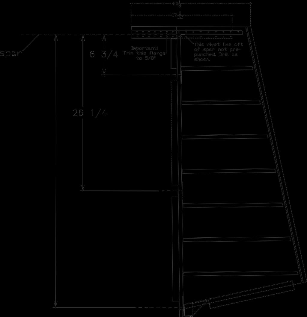
97 Technical Support: Page 97 The next operation will use the H Stab as a fixture to assemble the elevator spars: FITTING THE Wd-005 TO THE H Stab AFT SPAR We suggest that you locate the weldment to the spar by attaching the elevator spars and weldments to the H Stab (use the H Stab as a fixture to assemble the elevator spars as shown below). Drill the Wd-005 pivot attach hole to 1/4, and bolt both Wd-005 horns to the center pivot flange bearing (2 ea regular AN washers next to the bearing) so they are positioned and aligned correctly. NOTE: Inspect the pivot attach/horn area of the Wd-005 for deformation. We have seen some minor deformation in the area of the horn/tube weld straighten this area as required so the horn is 90 deg to the centerline of the spar when bolted up. Install and adjust the rod ends onto the spars as shown (13/16 ), and temporarily attach the spar to the stab pivot brackets using AN3 bolts. Position and clamp the root ends of the spars to the Wd-005 horns, and drill #30 thru the prepunched holes in the 005 horns and the spars. Test fit the tip ribs to the spars at this point, to see if you will have to adjust their locations to allow proper spacing between the inside edge of the counterweight and the outer edge of the stab skin. Remove the spar assy, deburr, and rivet the Wd-005 to the spars using AN470AD4 rivets. If the arm of Wd-005 extending down the root rib does not fit exactly, and tries to twist the rib or spar, it may be filed or ground to fit. Also position the E-004 tip rib assy to the spar. Locate and drill an additional attach angle at the tip rib assy as you did with the rudder tip rib. Drill, deburr, and prime, the tip rib assy. 005 root ribs These ribs have a tab on the fwd end this is a tooling hole. Cut this tab off before using the part.
, using the noted rivet")

98 Page 98 Technical Support: DRILL THE COUNTERWEIGHT SKIN TO THE TIP RIBS Clamp and drill the counterweight skin to the tip ribs as shown in the photos (as you did with the rudder), using the noted rivet pattern and spacing. Be sure the leading edge of the skin is tight to the nose of the ribs before drilling. Deburr and dimple these attach holes, but do not rivet at this time. You will use the same assembly sequence as was used during the assembly of the rudder (the counterweight skin will be riveted to the elevator skins prior to final riveting of the elevator). Rivet the tip rib assys to the ends of the spars. Do not proceed farther than this with the counterweight skins & ribs.

99 Technical Support: Page 99 TRAILING EDGES Clamp and drill the elevator trailing edges using the same procedure as you did with the rudder skins. Do both left and right elevator skins and their respective trailing edge doublers at this time. FITTING THE SKELETON TO THE ELEVATOR SKIN Remember: The rudder fixture will not work because the elevator cross section is different than that of the rudder. A new fixture will have to be fashioned, using different blocks made for the elevators. Locate and assemble the fixture for the elevators onto the worktable. Level and plumb it accurately. Put the E-001 skins (clecoed at the TE) in the jig. Slide the rib/spar skeleton into the skin, just as you did with the rudder. Locate and clamp the spar to the skin, then align the root ribs (the root ribs will align with the holes in the skin) and clamp them. Slip the E-013 counterbalance skin in place, between the elevator skin and the tip ribs, and cleco this skin to the E-003/E-004 tip ribs. Align the outer edge of the counterbalance skin with the edge of the E-001 skin, and clamp in place. Drill the skin to the spar and root rib. Position and clamp the skeleton to the skin (in the fixture) Align the spar flanges with the edges of the pivot bracket cutouts, and the root rib with the edge of the skin. Align the counterweight skin with the outer edge of the skin.


100 Page 100 Technical Support: Proceed to drill along the spar and root rib, keeping the skin clamped tightly. With the tip area clamped tightly, check the counterweight for alignment (make sure the sides of the counterweight point to similar areas near the root rib use a ruler as a sighting device to check this) and drill the counterweight skin to the main skins by simply extending the rivet lines in the fwd section of the counterweight. CAUTION: watch the holes near the spar for proper positioning and ED.
, clamp, and drill the E-012 counterweight skin")
101 Technical Support: Page 101 Align (carefully in two planes: the counterweight ribs must be 90 deg from the elevator spar, and also not twisted when viewed from above), clamp, and drill the E-012 counterweight skin to the tip rib and skin. As was done on the rudder, extend the rivet line in the E-004 rib aft of the E-002 spar. Disassemble the elevator, deburr, dimple and prime as desired. Rivet the counterweight skin to the main elevator skins as you did with the rudder.


102 Page 102 Technical Support: Cleco the skeleton into the skin assy, and put this assy into the fixture blocks. Rivet the elevator as you did the rudder. Complete the leading edge bend of the E-001 skins as was done with the rudder, and rivet the rivet line along the leading edge using the AVEX LP4-3 pull-type rivets


103 Technical Support: Page 103 Lay out the rivet line for attaching the servo bracket to the access panel and drill these holes to #40 Simply lay the servo bracket on the assembled doubler/access cover assy, center it in the opening, and drill the attach holes. Cleco the assembly to the tabletop as you drill the holes. DO NOT RIVET THE BRACKET TO THE COVER AT THIS TIME.

 to #30.")
104 Page 104 Technical Support: After the bracket attach holes are drilled, remove the bracket and access cover from the doubler. Deburr and dimple the bracket and the cover plate. DO NOT RIVET THE BRACKET TO THE COVER AT THIS TIME. Drill the cover plate attach fastener holes (in the skin) to #30. Position the doubler as shown, and cleco in place using the cover plate attach fastener holes. Drill the remaining doubler attach holes thru the skin to #40 as shown.

 where the")
105 Technical Support: Page 105 Drill the cover plate attach fastener holes to #19 for the #8 screws, and dimple as shown below. Dimple the #40 holes (both in the doubler and the skin) where the doubler will attach, and rivet the doubler to the skin.
106 Page 106 Technical Support:
107 Technical Support: Page 107 SUBASSEMBLY 5: THE LEFT ELEVATOR & TRIM TAB The left elevator with the trim tab seems to be the most frequent source of builder error in the empennage. It IS slightly more difficult than the right elevator. With the practice and experience you've gained on the rudder and right elevator, and with careful attention to the plans, you will get good results. BEGINNING THE LEFT ELEVATOR Repeat the procedures for fitting the skin to the spar (the stiffeners should be done already). The only difference on the left elevator, vs. the right elevator, is the use of the E-006 rear spar. Repeat the procedures for building the skeleton of the right elevator for the left elevator. The E-006 rear spar is not riveted to the E-005 end rib and floats until it is joined to the skin. FITTING THE SKELETON AND SKIN OF THE LEFT ELEVATOR Fit the skeleton to the skin in the same jig you used for the right elevator. An additional center V-block will hold the elevator skin just outboard of the trim tab cutout and provide additional rigidity. This helps avoid the tendency for the trailing edge to bend at the juncture of the trim tab and outboard elevator skin. Mount the E-001 elevator skin assy in the V- Block fixture. Draw centerlines on all the ribs and E-006 rear spar, then slide the skeleton in place. Clamp the main spar to the skin, with the edge of the spar flange even with the edge of the pivot cutouts, and clamp the rest of the skeleton so that all the lines on the ribs, and the rear spar. are showing through the holes in the skin. Drill the skin to the skeleton. Remove the E-006 spar from the assembly so you can attach the trim tab hinge to the spar. Position the hinge on the spar as shown in the photos, and drill for the 4 tack rivets (NAS1097AD3). Squeeze these rivets, and replace the spar onto the elevator assembly. Drill thru the hinge, using the existing holes in the skin and spar. Remove the skeleton, deburr, dimple, and prime as desired. You can also dimple the skin at this point.


108 Page 108 Technical Support: As with the right elevator and the rudder, set the skins into the fixture and clamp the skeleton into position. Our technician cut a block to be inserted into the root rib block (used in assembling the right elevator) to convert that block to be used in the center of the left elevator.


109 Technical Support: Page 109 Position and clamp the root rib securely. Note the positioning of the trim tab hinge in this photo. The section view of the trim tab shows the hinge on the inside of the spar. It appears to fit better if the thinge is installed between the skin and the spar (as shown here), giving a smoother profile to the surface of the elevator.


110 Page 110 Technical Support: The tip end of the trim tab hinge ended up like this Note the approx. 040 clearance between the end of the hinge and the edge of the skin. Once you are certain of the positioning and alignment of all the parts in the tab spar area, drill the attach holes into the root rib, spar, and hinge as shown.


111 Technical Support: Page 111 Then remove the spar and hinge. Re-cleco the hinge to the spar, and drill for the NAS1097 tack rivets as shown by the crosses drawn on the assembly. The tack rivets will keep the hinge correctly positioned on the spar while you machine countersink for the spar attach rivets. The tack rivets are installed as shown (total of 4 rivets are used).a


112 Page 112 Technical Support: Remove the spar from the fixture, and rivet the Wd-005 to the root rib (AN470AD4 rivets). And position the skins and sketeton back into the fixture Drill the counterweight area to the main skins and tip rib as you did with the right elevator. Remove the assembly from the fixture, de-burr and dimple.
.")
113 Technical Support: Page 113 Rivet the counterweight skin to the main skin as you did with both the rudder and the other elevator (shoot the rivets aft of the spar and inside the tip rib). And put the elevator assembly back into the fixture for final riveting. Check the counterweight again to make sure it is properly aligned, before riveting in that area.

114 Page 114 Technical Support: Roll the leading edge as you did on the rudder and right elevator; rivet closed with AVEX LP4-3 pull type rivets. It s time to build the trim tab!
115 Technical Support: Page 115 BUILDING THE TRIM TAB Refer to the drawing below during assembly of the trim tab. The trim tab is essentially a right elevator. Keep this in mind while building this part, and you should be able to side-step most of the pitfalls associated with this seemingly innocent part. With the tab hinge section pinned to the elevator (the front half will be already riveted to the left elevator), locate the tab spar onto its hinge section. Noting (from the pre-punched skin) where the skin rivets will fall, drill a few tack rivet holes thru the tab spar/hinge assy in between the skin rivet locations. Remove the hinge section and spar, and rivet these together using NAS1097AD3 rivets, keeping the surface which will be under the skin smooth. Pin the spar/hinge assy to the elevator again, and locate the upper skin on the spar. Drill the skin to the spar. Before riveting the tab top skin to the tab spar, you will machine countersink the spar/hinge assy, and dimple the skin. Remove the tab spar/hinge assy from the left elevator. Drill & cleco the trailing edge of the trim tab as you did with the rudder and elevators. Cleco the skin assy to the spar, using the holes drilled in the upper surface of the spar. Locate the root & tip ribs, and drill these to the upper skin only. Pin the spar/hinge/skin assy to the elevator again. Clamp a straight edge along the trailing edges of the elevator and the tab, to lock the alignment of these edges. Drill the lower tab skin to the lower flange of the tab spar., and then drill the tip and root ribs to the lower tab skin. Locate and drill the actuator arm to the root rib area, and fabricate the actuator arm support as shown in the photos. Remove the tab assy from the elevator, deburr, dimple, and rivet together.

 where the skin rivets will fall, drill a few tack")
116 Page 116 Technical Support: With the tab hinge section pinned to the elevator (the front half will be already riveted to the left elevator), locate the tab spar onto its hinge section. BELOW: Noting (from the prepunched skin) where the skin rivets will fall, drill a few tack rivet holes thru the tab spar/hinge assy in between the skin rivet locations.


117 Technical Support: Page 117 Remove the hinge section and spar, and rivet these together using NAS1097AD3 rivets, keeping the surface which will be under the skin smooth. Pin the spar/hinge assy to the elevator again, and locate the upper skin on the spar. Drill the skin to the spar.


118 Page 118 Technical Support: Before riveting the trim tab top skin to the trim tab spar, you will machine countersink the spar/hinge assy, and dimple the skin. Drill & cleco the trailing edge of the trim tab as you did with the rudder and elevators. Cleco the skin assy to the spar, using the holes drilled in the upper surface of the spar. Locate the root & tip ribs, and drill these to the upper skin only.


119 Technical Support: Page 119 Pin the spar/hinge/skin assy to the elevator again. Clamp a straight edge along the trailing edges of the elevator and the tab, to lock the alignment of these edges. Drill the lower tab skin to the lower flange of the tab spar., and then drill the tip and root ribs to the lower tab skin. The trim tab actuator horn will require an additional attach angle. Make this from.032 material, and use existing holes to attach this part to the trim tab. Drill & rivet (use an AN470AD4-4 rivet) the two horns together also keep this rivet 1/2 from the actuator rod attach hole. NOTE: later kits have this additional support angle included.


120 Page 120 Technical Support: Align the actuator horn on the trim tab with the slot in the elevator. Locate and drill the actuator arm to the root rib area. Early kits will require that you fabricate the actuator arm support as shown in the photos.


121 Technical Support: Page 121 The finished actuator horn should look similar to this.


122 Page 122 Technical Support: Enlarge the length of the tab actuator rod by 1/2 as shown before fitting the actuator rod to the assembly. Drill the servo mounting bracket to fit the servo; fit 4 ea #6 nutplates to the bracket as shown.


123 Technical Support: Page 123 A bottom view of the servo bracket with nutplates installed. Attach the servo as shown using #6 machine screws.

124 Page 124 Technical Support: The servo cannot be fitted into the elevator as supplied; the threaded rod will block this fit. Use a 9V battery to run the servo motor in the proper direction to make the threaded rod flush with the surface of the fwd side of the servo as shown.
125 Technical Support: Page 125 THIS PAGE INTENTIONALLY LEFT BLANK
126 Page 126 Technical Support:
127 Technical Support: Page 127 FITTING THE FIBERGLASS TIPS. There are several ways and times that fiberglass tips may be mounted. Some builders prefer to wait until the airplane is basically complete before installing any of the fiberglass, then do it all at once. Others like to complete each assembly as they go. It's your choice. Remember to consider things such as lighting installations, access to lights and bolts, etc. If you choose to install the empennage tips at this point, here are some generic instructions (actual installation photos are on the following pages): The molded fiberglass rudder bottom provided with the kit is designed with an aluminum-under-fiberglass joint. The other tips are intended to fit under the aluminum, but it is very difficult to mold a recess so thin into small fiberglass parts, so the joints may require some filing or sanding for a really smooth fit. BUILDER OPTION: you can install doublers (as is done at the rudder bottom) and install the tips in this manner. An additional option with this method is: you can either attach the tips using the provided CS4-4 pull-type rivets or AN426A3 soft rivets, or opt for using #6 or #8 countersunk machine screws and nutplates. The screw-on op tion allows for easy removal or replacement of the tips. The elevator tips fit particularly well, so these will likely be installed using the molded-in joggle and CS4-4 rivets and/or a bonding agent, or again the screw-on method. Note the aluminum doublers attached to the inside of the flange area of the elevator tips before final installa tion. The tips can be attached using the provided CS4-4 pull-type rivets or attached with AN426A3 soft rivets, or simply bonded in their respective locations, or a combination of both. During molding and storage, fiberglass parts may shrink or warp. Fortunately, fiberglass has some thermoplastic qualities, which means that it can be heated and reformed and will hold the new shape as it cools. Dipping the fiberglass part in very hot tap water will make it pliable until it cools, so parts may be, to a small degree, reformed. Larger parts may be heated with a hair dryer or (carefully!) with a heat gun.

, placing two rivets 1/2 fwd & aft of the fwd edge of the elevator skin as shown.")
128 Page 128 Technical Support: Empennage Composite Tip Installation Of course, the empennage will get composite tips installed. Start but marking the rivet line for the elevator tip onto the elevator. Use 2 sp on the rivets (min.), placing two rivets 1/2 fwd & aft of the fwd edge of the elevator skin as shown. Position the elevator tip as shown. The flange may require some fitting near the trailing edge area for a better fit.


129 Technical Support: Page 129 The elevator tip will need an aluminum doubler strip installed to keep the AVEX pull rivets from damaging the composite structure. This strip is 5/8 wide, made from 025 or 032 scrap material. Note the attach rivet locations, and use NAS1097AD3-3.5 rivets, positioned between the tip attach rivets, to install the strips. The lower photo shows a close up of the fwd end of one of these strips.

130 Page 130 Technical Support: One the doubler strips are riveted in place, you can locate and drill the tip to the elevator, using the pre-marked hole locations.


131 Technical Support: Page 131 FITTING THE RUDDER TIPS The rudder bottom cap must clear the tailwheel spring. Trim the cap so the bottom of the cap (measured at the fwd end) measures 4 3/4 from the upper edge of the lower pivot cutout. Drill the lower cap attach holes at 2 sp. Be sure to get two holes thru the sides of the R-010 horn brace as shown. The lower cap will attach with AVEX LP4-3 pull type rivets.


132 Page 132 Technical Support: Most of you will be running navigation lights on your ships. The next few pages detail one method of installing the light into the bottom of the rudder: First, drill out a hole big enough for your light assembly in the molded fairing. Allow 1/32 clearance around the light assembly. Trace the retainer ring onto a piece of 1/8 aluminum material. Cut out the part as drawn. Overlay the lens retainer after you have fabricated this piece, and drill for the lens retainer ring attach fasteners. Tap the 1/8 assembly retainer for the lens retainer ring screws (#6-32 in this case). The assembly retainer will be glued into the light fairing next.


133 Technical Support: Page 133 The fairing will likely be cut as shown (before fitting the light assembly retainer ring). Mix resin, activator, and milled fibers to make the glue for the retainer ring. Glue the retainer ring into the fairing as shown. Use the light assembly as a fixture to hold the ring in the proper position while the resin sets up. Be sure to rough up the inner sfc of the area to be glued. You will note we also attached 2 pcs of composite to the aft end of the rudder cap to keep it centered. No fasteners are used in these flanges in final assembly.


134 Page 134 Technical Support: The retainer ring will look like this after the glue sets up. And the final fit looks good! This particular installation will have a rudder mounted strobe in addition to the navigation light. The power supply for the strobe will be mounted to the F-019 deck, between the root ribs of the H Stab.


135 Technical Support: Page 135 The rudder upper cap can be installed inside the rudder skin as supplied, or installed over aluminum doubler strips as shown. Cut strips 1 1/2 wide for this attach method, ans rivet to the upper area of the rudder skin with AN426AD3-3.5 rivets. The cap will then be installed to the doublers with AVEX CS4-4 rivets. Alternatively, the upper cap can be installed as the elevator tips were, using the same style double strip and AVEX CS4-4 rivets. The rudder cap doublers are riveted to the rudder, and the cap and doublers are drilled #30 for the attach rivets.

136 Page 136 Technical Support: Fit the rudder to the fin to mark an even upper edge on the fin. Remove the rudder, trim the fin at the line, and install the fin tip attach doublers as shown on the following pages.
 is bolted to the rudder counterweight as shown, using AN970-3 washers")

137 Technical Support: Page 137 The rudder counterweight (830G) is bolted to the rudder counterweight as shown, using AN970-3 washers inside the counterweight ribs. The attach doublers show signs of the shrinking process, necessary to get the tapered cap to fit properly. This photo shows the bottom side of the rudder counterweight. Note that the upper cap is riveted to the rudder in this photo. Pre-cast counterweights are available from Van s Aircraft.


138 Page 138 Technical Support: This cap did not conform quite exactly in the corners. We added a resin/flox mixture under the composite material to allow for sanding to the proper shape later. Note the duct tap over the aluminum to keep the resin from sticking to that area. And a finished rudder cap! The cap is 4 1/4 high at the front; 3 1/2 at the rear. The V Fin cap is attached in the same manner as the H Stab tips. Set the height if the V Fin tip to make a smooth transition to the rudder cap.


139 Technical Support: Page 139 Fabricate the fin tip attach doublers as shown. The rivet spacing is approx. 1 1/4 at the doubler attach. The fwd ends of the double may need to be formed inward a bit to allow the tip to fit correctly. Fit the fin tip so it matches the profile of the rudder tip. Drill for the attach fasteners (AN426A3-5 soft rivets) at 1 1/4 SP. Smooth the lower edges of the tip before riveting.
140 Page 140 Technical Support: THIS PAGE INTENTIONALLY LEFT BLANK


141 Technical Support: Page 141 Trim the notch in the stab skin for 3/16 clearance at the leading edge of the counterweight, matching the clearance along the tip rib/counterweight. It is necessary to notch the lower flanges of the H Stab aft spar to get the correct downward deflection of the elevators. Remove material from the flange to allow 1/16 clearance at the sides of the elevator horns, and also to allow contact between the horns and the center bearing attach fasteners. NOTE: make sure the center bearing bracket attach bolt heads face aft. This allows for more elevator travel.

142 Page 142 Technical Support: A finished cutout will look like this. Photo courtesy Eric Henson

.")
143 Technical Support: Page 143 If the H Stab tip is trimmed parallel with the tip rib, the composite tip will not fit up correctly (the front corner will be trimmed to far into the radius). So mark the H Stab tip so the cut line is an extension of the tip edge of the elevator as shown.


144 Page 144 Technical Support: Also mark the bottom sfc of the stab, and check that the marked cut lines match exactly at the leading edge. Then, trim the stab skin as marked. Insert the stab tip as shown. Check to make sure it lines up with the elevator tip, and mark it for cutting.


145 Technical Support: Page 145 Fabricate two aluminum doubler strips for attaching the tip, as you did with the V Fin tip. These strips will be 1 1/8 wide, with 50% protruding from the edge of the stab for the tip attach. Drill the attach holes at 1 1/4 sp. As with the V Fin tip attach doublers, these may need some forming to get an exact fit. Now that the tip is trimmed and the attach doublers are riveted in place, locate and drill the tip onto the doublers. Mark the aft edge of the tip for trimming after it is drilled, remove the tip & trim. Sand all edges to a smooth contour.


146 Page 146 Technical Support: A second view of the tip, prior to trimming. Rivet the tip in place using AN426A3-5 rivets (soft rivets). You can trim the rivtes to length with a good pair of side cutters if desired. Note the rivet spacing and positioning.
 THRU THE WEBS OF")

147 Technical Support: Page 147 POURING THE ELEVATOR COUNTERWEIGHTS IMPORTANT: INSTALL DOU- BLE-NUTTED HARDWARE STORE BOLTS (WITH FENDER WASHERS) THRU THE WEBS OF THE ELEVA- TOR COUNTERWEIGHT RIBS BEFORE POURING ANY WEIGHTS. THE POURED WEIGHTS WILL NOT RE- MAIN IN PLACE WITHOUT SOME TYPE OF RETAINING FASTENERS! TWO FASTEN- ERS PER SIDE ARE RE- QUIRED. NOTE THE FWD FASTENER IS LONG ENOUGH TO RETAIN THE SECOND WEIGHT, TO BE POURED ON TOP OF THE FIRST WEIGHT (ON THE OUTBOARD SIDE OF THE RIB ONLY). Note the installation of the fender washers on both fasteners.


148 Page 148 Technical Support: Only the fwd fastener will get the fender washer on the inside of the counterweight, as this weight is smaller than the outboard weights. The length of this weight is 2 3/4-2 7/8. Pour it up even with the edge of the counterweight skin. You will drill holes in this weight after painting to balance the elevators. The finished inner weight should look like this. The weight will be filled, painted, & sanded smooth after balancing.

149 Technical Support: Page 149 This picture shows one of the outboard elevator counterweights poured in place. We used the resin/milled fiber/lead shot mixture method here, with good results. We will make a second pour on top of this weight (see bottom picture) to keep most of the weight as far forward as possible. The first weight poured into the outboard side of the rib is 6 1/4 long. After this weight sets up, you will mount the elevators onto the H Stab to see what will be required for balance. This additional weight should be about 3 oz (90g) heavier than required for an exact balance. One builder purchased the pre-cast weights from Van s Aircraft. Since these elevator weights are not heavy enough, he cut one weight in two, and mounted that extra piece on top of the outer weight, at the fwd end of the counterweight. This is covered by the tip fairing in final assembly.
CENTER WING SECTION (CWS) WORK REPORT
 WORK REPORT") CENTER WING SECTION (CWS) WORK REPORT No. Check Parts / Description Qty PHASE 1: Preparations 1 [ ] 6V1-3 Rear ribs 2R & 2L 1 [ ] L Angle 6 2 [ ] 6V2-1 Rear Ribs.032 2R & 2L 2 [ ] 6V5-1 Gear Rib Doubler
CENTER WING SECTION (CWS) WORK REPORT No. Check Parts / Description Qty PHASE 1: Preparations 1 [ ] 6V1-3 Rear ribs 2R & 2L 1 [ ] L Angle 6 2 [ ] 6V2-1 Rear Ribs.032 2R & 2L 2 [ ] 6V5-1 Gear Rib Doubler
Rev: 01 Sept Technical Support: 01 Sept Evo Wing Assembly. F1 Evo Assembly Manual Chapter 6
 Page 1 01 Sept 2007 Evo Wing Assembly F1 Evo Assembly Manual Chapter 6 Page 2 Technical Support: mark@teamrocketaircraft.com F-1 Evo Suggested Wing Assembly Methods FIRST EDITION DECEMBER 2004 01 SEPT
FORWARD FUSELAGE SIDES & REAR TOP SKINS
 FORWARD FUSELAGE SIDES & REAR TOP SKINS WORK REPORT Step No. Check Parts / Tools Qty Preparations. 1 [ ] 6F5-3 Upper Front Longerons 2 2 [ ] 6F5-5 Heel Support 1 3 [ ] 6F5-2 Front Floor Skin 1 3 [ ] Firewall
SERVICE BULLETIN
 SERVICE BULLETIN 16-03-28 Date Released: May 6, 2016 (Initial Release) June 2, 2016 (Added Note, pg.11) Date Effective: May 6, 2016 Affected Models: Subject: Required Action: All RV-3, 4, 6/6A, 7/7A, 8/8A,
REVISION DESCRIPTION:
 REVISION DESCRIPTION: Page: 09-10 REV 1: Delete Step 1. 14401 Keil Road NE, Aurora, Oregon, USA 97002 PHONE 503-678-6545 FAX 503-678-6560 www.vansaircraft.com info@vansaircraft.com Service Letters and
STOL CH 801 SECTION 2: Nose Rib 8R1-7
 SECTION 2: Nose Rib 8R1-7 Position the lower nose rib on the front of the spar at the predrilled holes just above rear rib #3 (615mm from the bottom of the spar) Check lateral alignment (rib is centered
2.1 Parts List Tool requirement Before you start assembling the Stabiliser Front Spar Center Doublers...
 Stabilizer Assembly 2.0 Exploded View...Error! Bookmark not defined. 2.1 Parts List...3 2.2 Tool requirement...5 2.3 Before you start assembling the Stabiliser...6 2.4 Front Spar...6 2.5 Center Doublers...7
WING ASSEMBLY 23.5 (Continued)
") A VERY IMPORTANT NOTE found on many wing drawings states Do not drill any unspecified holes into spar. This is extremely important as any extra holes may, under extreme conditions, WEAKEN THE SPAR. Note;
A VERY IMPORTANT NOTE found on many wing drawings states Do not drill any unspecified holes into spar. This is extremely important as any extra holes may, under extreme conditions, WEAKEN THE SPAR. Note;
9.3 FUSELAGE ASSEMBLY 14/03/02
 9.3 MATING THE TAIL CONE TO THE CABIN 1) Trim the bottom flange of both FUS-339 side skins on the tailcone assembly as in Figure 1. 2) Remove the bottom two RBULK 2A s of bulkhead A on the tailcone. 3)
Elevator Assembly. To assemble the SR3500 Elevator, you will need the following tools:
 Elevator Assembly To assemble the SR3500 Elevator, you will need the following tools: 1. Drill 2. Tape Measure 3. Felt Marker 4. #40, #30, 3/16, #11 Drill Bits 5. #40, #30 and 3/16 Clecos 6. Cleco Pliers
Page: REV 1: Step 5 and Figure 5 updated to better describe the potential necessity of modifying a rivet squeezer yoke.
 14401 Keil Road NE, Aurora, Oregon, USA 97002 PHONE 503-678-6545 FAX 503-678-6560 www.vansaircraft.com info@vansaircraft.com Service Letters and Bulletins: www.vansaircraft.com/public/service.htm REVISION
ZODIAC CH 601 Series Kit Aircraft
 ZODIAC CH 601 Series Kit Aircraft THE FOLLOWING IS A DRAFT MANUAL This manual has been written and published strictly for informational purpose. It has been prepared as a guide to facilitate the assembly
12. Wings, Flaps, Ailerons and Struts
 12. Wings, Flaps, Ailerons and Struts Fit Aileron Hinges Reference: Drawing 20270K2 Photo 12.1 Parts Required: 2007092 Aileron LS 200809N Aileron RS 2001394 Hinge 3/16 A1 (4) 2001694 Hinge Pin (4) PH0059N
STOL CH H3-3SP Center Hinge Bracket. IMPORTANT: The Bracket 7H5-3SP is not symmetrical
 7H3-3SP Center Hinge Bracket IMPORTANT: The Bracket 7H5-3SP is not symmetrical Using a square helps layout and mark the perpendicular and the hinge hole. Note: Position of 1/4 hinge hole is 115.5mm from
ZODIAC CH 601 Series Kit Aircraft
 ZODIAC CH 601 Series Kit Aircraft THE FOLLOWING IS A DRAFT MANUAL This manual has been written and published strictly for informational purpose. It has been prepared as a guide to facilitate the assembly
ZODIAC 601 XL. ZODIAC CH 601 Series. Parts are labeled for easy identification with a part number and description:
 CH 601 Series Parts are labeled for easy identification with a part number and description: Part number example: 6T4-4 Vertical Tail Spar 6 - Zodiac CH 601 model T - Rudder section of the Aircraft drawings.
Flaperon Assembly Manual
 Flaperon Assembly Manual for PegaStol Aftermarket Wings A Senior Project presented to The Faculty of the Aerospace Engineering Department California Polytechnic State University, San Luis Obispo In Partial
Page: REV 2: Added "Step 1: Straighten the W-0007B Rear Spar Reinforcement Fork as described on Page 10-03, Step 4."
 14401 Keil Road NE, Aurora, Oregon, USA 97002 PHONE 503-678-6545 FAX 503-678-6560 www.vansaircraft.com info@vansaircraft.com Service Letters and Bulletins: www.vansaircraft.com/public/service.htm REVISION
ZODIAC CH650. ZODIAC CH 650 Series. Parts are labeled for easy identification with a part number and description:
 CH 650 Series Parts are labeled for easy identification with a part number and description: Part number example: 6T4-4 Vertical Tail Spar 6 - Zodiac CH 650 model T - Rudder section of the Aircraft drawings.
10. Wing prep and subassembly
 Date Section Objective: Construct and fabricate the sub-assemblies of the wing panel. Required Parts: Wing left 11gal PN104-300, Wing right 1gal PN104-400, Wing left 15 gal option PN104-322, Wing right
FUSELAGE CONSTRUCTION
 FUSELAGE CONSTRUCTION Note: prior to building and gluing on the work surface use protective covering on your building surface. (wax paper or clear wrap) Fit the laser cut Fuselage Front and Fuselage Rear
STANDARD CANOPY WORK REPORT B-1
 STANDARD CANOPY WORK REPORT B-1 No. Check Parts / Tools Qty _ Canopy Lock 1 [ ] 6E2-3 Canopy Hinge Block 1 2 [ ] 6E4-5 Canopy Side Frame 2 2 [ ] 6E2-1 Canopy Lock Assembly 1L + 1R 3 [ ] 6E2-4 Rear Lock
RESolution V2 Manual
 RESolution V2 Manual Note for the German Manual: Yellow Bottle thick CA Pink Bottle Med CA Blue tube 5 minute Epoxy Green tube 90 Minute Epoxy Construction of the Fuselage Step 1: Cover the plan with a
SE5a Wing Panels rev 1.0
 SE5a Wing Panels rev 1.0 The top and bottom wings are different. They might look the same but the bottom wing has one less rib and some rib spacing difference. This is due to where the wooden interplane
Chap. 9.2 SR3500 Fuselage Assembly - Cabin. MODEL: SR Murphy Aircraft Mfg. Ltd. All rights reserved.
 26/06/2006 Page 1 26/06/2006 Page 2 26/06/2006 Page 3 Parts List for Gear Box No. Part Number Description Qty Required 1,23 FUS0711QL BRACING CHANNEL 2 2,22 FUS0711QR BRACING CHANNEL 2 3 FUS301QB CARRYTHROUGH
Note - the nose ribs and are thinner than the main ribs. These nose ribs will use a thinner rib cap than the ribs. This is per design.
 Stabilizer rev 1.2 The SE5a stabilizer is the heartbeat of the tail and is recreated like the full scale version. All tail pieces depend on the stabilizer. It uses the steel fittings, pulleys, inspection
Ch. 9.0 ELITE FUSELAGE ASSEMBLY 14/02/2003
 Fuselage Assembly In the front of the fuselage manual you will find an exploded view of the fuselage and a side view schematic. We suggest that you tape these to the wall of your workshop. Refer to them
Cathy and Phil Cobbin's RV7A Project 2003 Photo Log
 Cathy and Phil Cobbin's RV7A Project 2003 Photo Log 1 of 60 2003 09 22 Arrival of the empennage kit 2 of 60 2003 09 23 Cleco horizontal stabilizer rear spar together to file/fit the radius to clear the
REAR FUSELAGE ASSEMBLY
 SECTION 2 Rear Fuselage Bottom Assembly Ref Dwg 8FR-2 SECTION 2 - Page 1 of 17 FUSELAGE BOTTOM SKIN 8F2-3A Note: The edges of skin 8F2-3A are not a straight line. Check: edge distance from the center of
SZD-10 bis CZAPLA ASSEMBLY MANUAL IN PICTURES
 1 RUDDER Plan and parts: 2 Assembly steps: Photo above: glue together rudder spar, ribs and trailing edge. Clamp spar to a flat surface (chipboard on the photo) and make sure the straight aligment of the
Photo-Guide (ZE & ZE )
") Photo-Guide (ZE-2009-05 & ZE-2009-07) The following photo-guide is for educational purposes only. It is intended to assist owners and/or aircraft mechanics with the installation of elements from from 6Z-1G
Photo-Guide (ZE-2009-05 & ZE-2009-07) The following photo-guide is for educational purposes only. It is intended to assist owners and/or aircraft mechanics with the installation of elements from from 6Z-1G
16. Wing Final Assembly and Installation
 Section Objective: Installation and rigging of ailerons. Pitot tube install, and any other wing related items. Required Parts: Left aileron push rod ALA-0072, Right aileron push rod ALA-0073, Push tube
SERVICE BULLETIN. No. SB-AG-45 Rev. B JUNE 1, 2007 FIN SPAR & ATTACH FITTINGS INSPECTION AND UPGRADE IMPORTANT:
 THRUSH AIRCRAFT, INC. P.O. Box 3149 300 Old Pretoria Rd. Albany, GA 31706-3149 Product Support 229-883-1440 ext. 341 FAX 229-436-4856 jbays@thrushaircraft.com SERVICE BULLETIN No. SB-AG-45 Rev. B JUNE
STOL CH 701. Standard L ANGLES are supplied in 4ft length. Ref. bottom left diagram on drawing 7-V-2
 Standard L ANGLES are supplied in 4ft length. Ref. bottom left diagram on drawing 7-V-2 Length = 206mm. Layout the cut line on the outside flanges. Ref. see boxed diagram on drawing 7-V-2 Three vertical
Section 75-AA-1. Flaperon Assembly
 Section 75-AA-1 This manual has been prepared for assembly of the flaperons supplied with match drilled parts. This photo assembly manual is intended as a supplement to the drawings. If there is any discrepancy
STOL CH 701. Clamp a reference extrusion on the bottom of the spar. Clamp the bottom flange of the rib to the extrusion. Rear Root Rib 7V4-2
 Rear Root Rib 7V4-2 Clamp a reference extrusion on the bottom of the spar. Clamp the bottom flange of the rib to the extrusion. Cleco the root nose rib to the spar Position the rear root rib at station
11) Chromate the mating surfaces of the Leading edge Root Rib, Doubler and Root Rib Stiffeners. Rivet together with 1/8 rivets (RV-1410).
 Chromate the mating surfaces of the Leading edge Root Rib, Doubler and Root Rib Stiffeners. Rivet together with 1/8 rivets (RV-1410).") 11) Chromate the mating surfaces of the Leading edge Root Rib, Doubler and Root Rib Stiffeners. Rivet together with 1/8 rivets (RV-1410). 12) Chromate the Root Rib Attach Bracket and rivet to the Root
11) Chromate the mating surfaces of the Leading edge Root Rib, Doubler and Root Rib Stiffeners. Rivet together with 1/8 rivets (RV-1410). 12) Chromate the Root Rib Attach Bracket and rivet to the Root
Section 6-T-3 Elevator
 Section 6-T-3 Elevator This manual has been prepared for assembly of the Elevator using match drilled parts. This photo assembly manual is intended as a supplement to the drawings. If there is any discrepancy
STOL CH nd Edition Drawings July 20, 2010 Summary of changes from Edition 1 to Edition 2.
 STOL CH 750 2 nd Edition Drawings July 20, 2010 Summary of changes from Edition 1 to Edition 2. Page Date Drawing Title 75-G-0 07/10 Three View Drawing 75-G-1 07/10 Drawings Index 75-G-2 03/10 General
STOL CH st Edition 1 st Revision Drawings Summary of changes from Edition 1 to Edition 1 Revision 1.
 STOL CH 750 1 st Edition 1 st Revision Drawings Summary of changes from Edition 1 to Edition 1 Revision 1. Page Date Drawing Title 75-G-0 01/10 Three View Drawing 75-G-1 01/10 Drawings Index 75-RX-1 05/09
Three vertical L angles must be riveted to each main spar (length = 206mm see boxed diagram on drawing 7-V-2).
.") Cut over-sized (left); Trim and file (above). Note: Six needed. Three vertical L angles must be riveted to each main spar (length = 206mm see boxed diagram on drawing 7-V-2). Trace line down center of
Cut over-sized (left); Trim and file (above). Note: Six needed. Three vertical L angles must be riveted to each main spar (length = 206mm see boxed diagram on drawing 7-V-2). Trace line down center of
Drilling Your Wings to Your Fuselage
 Drilling Your Wings to Your Fuselage The purpose of this write up is to give some further guidance on how to get the best results drilling your wing spar attach holes to the upper fuselage attach fittings.
75-TA-4. Elevator Skins
 75-TA-4 This manual has been prepared for assembly of the. This photo assembly manual is intended as a supplement to the drawings. If there is any discrepancy between this manual and the drawings, the
STOL CH 701. Layout the cut line along the bend tangent line on the web. 7V6-1 and 7V6-2SP
 Layout the cut line along the bend tangent line on the web. 7V6-1 and 7V6-2SP ORIENTATION: 90 degree flange is up Layout the bend line, 20mm from the end. Ref. bottom right diagram 7-V-6 Use a square to
Installation Instructions
 DODGE 16K Industry Standard Rail Custom Mounting Kit #2728 Gross Trailer Weight (Maximum)...16,000 lbs. Vertical Load Weight (Max. Pin Weight)...4,000 lbs. SYSTEM TOW CAPACITY Please note, in order to
TIGER MOTH 120 ASSEMBLY INSTRUCTIONS
 TIGER MOTH 120 ASSEMBLY INSTRUCTIONS SPECIFICATIONS Wing Span: Length: Radio: Flying Weight: 1920mm 1580mm 4 channel with 6 servos 4200g AILERON ASSEMBLY 1 Start by removing the servo cover from the bottom
ZODIAC CH 601 Series Kit Aircraft
 ZODIAC CH 601 Series Kit Aircraft THE FOLLOWING IS A DRAFT MANUAL This manual has been written and published strictly for informational purpose. It has been prepared as a guide to facilitate the assembly
Cut the center and pre-drill the Hinge Plate. Do not drill the Rudder Hinge hole at this time.
 7F4-1 Upper Rudder Hinge Plate Layout the cut for the Upper Hinge Plate. Measure and mark the center for the Rudder Hinge. The center hinge hole is 75mm from the back edge of 7F4-1. Cut the center and
Builders Log Report S
 12/09/01 Reamed Horizontal Stabilizer Bushings I reamed seven bushing locations to.4375 where elevator attaches to horizontal stabilizer. The proximity of the locations to structural tubing made it difficult
FLITZEBOGEN-2 Assembly instructions
 FLITZEBOGEN-2 Assembly instructions Trim the end of the fuselage to the length of 925mm from the nose. Be careful to avoid splitting the carbon fibers. Sand the base of the stab mount in preparation for
Section 75-ZA-2. Rudder Mounting
 Section 75-ZA-2 This manual has been prepared for installation of the Rudder. This photo assembly manual is intended as a supplement to the drawings. If there is any discrepancy between this manual and
SERVICE BULLETIN
 14401 Keil Road NE, Aurora, Oregon, USA 97002 PHONE 503-678-6545 FAX 503-678-6560 www.vansaircraft.com info@vansaircraft.com Service Letters and Bulletins: www.vansaircraft.com/public/service.htm SERVICE
ZODIAC 601 XL. Detail of outboard end. Full length recessed elevator trim tab. Detail of inboard end. Trim tab along left trailing edge of elevator.
 Full length recessed elevator trim tab. Detail of outboard end. Detail of inboard end. Trim tab along left trailing edge of elevator. Trim tab in neutral position 6-T-6 - Page 1 of 12 Drill out the middle
STC GROUP LLC 480 RUDDIMAN DRIVE MUSKEGON, MICHIGAN REPORT NO: G REV E TRIO AUTO PILOT INSTALLATION INSTRUCTIONS
 STC GROUP LLC 480 RUDDIMAN DRIVE MUSKEGON, MICHIGAN 49445 REPORT NO: G-1006-51 REV E TRIO AUTO PILOT INSTALLATION INSTRUCTIONS CESSNA MODEL 182 WITH PREVIOUS CESSNA EQUIPPED AUTO PILOT DATE: Original Issue
WING ASSEMBLY SECTION 4. Mounting Wing Ribs to Main Spar. 1. Identify the proper locations for those ribs with attachment brackets.
 WING ASSEMBLY SECTION 4 Mounting Wing Ribs to Main Spar Compass Check 1. Identify the proper locations for those ribs with attachment brackets. 2. Position and drill the nose ribs. 3. Un-cleco the nose
Installation Instructions
 FORD 20K Industry Standard Rail Custom Mounting Kit #2738 Gross Trailer Weight (Maximum)...20,000 lbs. Vertical Load Weight (Max. Pin Weight)...5,000 lbs. SYSTEM TOW CAPACITY Please note, in order to determine
Citabria Pro. Aerobatic Parkflyer. by Joel Dirnberger
 Citabria Pro Aerobatic Parkflyer by Joel Dirnberger Revision C: December 21, 2004 Citabria Pro Building Instructions Length: Wingspan: Wing Area: Flying Weight: Wing Loading: Functions: Specifications:
07 - Landing Gear. Landing Gear. February EGF Page 7-1
 Landing Gear February 2003 07-EGF Page 7-1 This Page Intentionally Left Blank Page 7-2 07-EGF February 2003 Contents 7.0 - Chapter Preface...7-4 7.0.1 - Parts List...7-4 7.0.2 - Tools List...7-4 7.0.3
STC GROUP LLC Page Ruddiman Drive PA-28 & PA-32 Trio Pro Pilot Installation Instructions North Muskegon, Michigan 49445
 STC GROUP LLC Page 1 STC GROUP LLC 480 RUDDIMAN DRIVE MUSKEGON, MICHIGAN 49445 DOCUMENT NO: 1028001 REVISION D TRIO PRO PILOT INSTALLATION INSTRUCTIONS PIPER AIRCRAFT CORPORATION PA-28 AND PA-32 DATE:
SERVICE BULLETIN
 SERVICE BULLETIN 14-02-03 Date Released: February 3, 2014 Date Effective: February 3, 2014 Subject: Affected Models: Required Action: Time of Compliance: Cracking in elevator spar web near elevator attach
96 WING SPAN SPITFIRE (COPYRIGHT PROTECTED 2014) ALL RIGHTS RESERVED
 ALL RIGHTS RESERVED") 96 WING SPAN SPITFIRE (COPYRIGHT PROTECTED 2014) ALL RIGHTS RESERVED GENERAL INSTRUCTIONS Should you elect to use the recommended Door Skin, which is 1/8 mahogany plywood measuring 36 x 88. Have it cut
96 WING SPAN SPITFIRE (COPYRIGHT PROTECTED 2014) ALL RIGHTS RESERVED GENERAL INSTRUCTIONS Should you elect to use the recommended Door Skin, which is 1/8 mahogany plywood measuring 36 x 88. Have it cut
Continue gluing the remaining top parts ensuring the angled piece is glued well. Set aside and let dry. See photo below
 Radiator rev 1.1 The SE5a s radiator is one of the most recognized radiators in WW1. It is one of the components that defines the SE5a. The original SE5a has seen multiple radiator designs used during
Installation Instructions
 CHEVY / GMC 20K Industry Standard Rail Custom Mounting Kit #2724 Gross Trailer Weight (Maximum)...20,000 lbs. Vertical Load Weight (Max. Pin Weight)...5,000 lbs. SYSTEM TOW CAPACITY Please note, in order
77.5 degrees REAR CHANNEL PLYWOOD TEMPLATE
 77.5 degrees REAR CHANNEL PLYWOOD TEMPLATE Ref. 6-B-14 Make following template: Vertical distance = 300mm Layout dimensions shown in the bottom right table on drawing 6-B-14 Top and bottom are square to
Building Tips This model can be built using the following types of adhesives:
 Page 1 Building Tips This model can be built using the following types of adhesives: Epoxy (with or without microballons) Odorless cyanoacrylate (CA) with accelerator UHU Creativ for Styrofoam (or UHU
Important Note. Tools Required: Welder capable of fully welding 10 GA.135 steel
 INSTALLATION INSTRUCTIONS Frame Reinforcement Kit 11100 (Patent Pending) 1968-72 GM A-Body Coupe/Sedan Read Instructions FULLY before starting Installation Important Note Installation of this kit requires
ULS Cherokee. Ultra Low Speed aircraft for indoor RC flying. Zippkits. Specifications: Required to complete:
 Zippkits ULS Cherokee Ultra Low Speed aircraft for indoor RC flying. Specifications: Span- 28 inches Wing Area- 151 Sq/In Wing Loading- 3.0 ounces/ft Weight- 3.5 ounces RTF Build time- 1-2 Hours Radio-
Section 6-B-6, 6-B-7, & 6-B-8 Firewall Assembly
 Section 6-B-6, 6-B-7, & 6-B-8 Firewall Assembly This manual has been prepared for assembly of the firewall supplied with match drilled parts. This photo assembly manual is intended as a supplement to the
Installation Instructions Universal Crossmember Kit - 60 Track Width BEFORE Measure Twice, Weld Once! II
 Installation Instructions Universal Crossmember Kit - 60 Track Width Please read these instructions completely BEFORE starting your installation. Remember the basic rule for a successful installation:
Section 75-FA-5. Firewall Assembly
 Section 75-FA-5 This manual has been prepared for assembly of the firewall supplied with match drilled parts. This photo assembly manual is intended as a supplement to the drawings. If there is any discrepancy
Fokker Dr1 Master Instructions
 Fokker Dr1 Master Instructions Rev 1 Congratulations on your new project. This Dr1 kit is the finest to date. The construction of the plane is similar and exactly like the original. Take your time and
Section C75-WA-1. Wing Skeleton
 Section C75-WA-1 This manual has been prepared for assembly of the wing skeleton supplied with match drilled parts. This photo assembly manual is intended as a supplement to the drawings. If there is any
2000 Tomlynn Street P.O. Box 6861 Richmond, Virginia / FAX 804/ Service Bulletin
 Sequoia Aircraft Corporation 2000 Tomlynn Street P.O. Box 6861 Richmond, Virginia 23230 804/353-1713 FAX 804/359-2618 Service Bulletin Service Bulletin No. 93-1 Subject: Flap Flutter Date: June 24, 1993
Installation Instructions
 FORD 20K Industry Standard Rail Custom Mounting Kit #2760 Gross Trailer Weight (Maximum)...20,000 lbs. Vertical Load Weight (Max. Pin Weight)...5,000 lbs. SYSTEM TOW CAPACITY Please note, in order to determine
Stream NXT - assembly instructions
 Stream NXT - assembly instructions Recommended settings CG (measured from root leading edge): Speed/launch camber (+down, near the wing root): Cruise camber (+down, near the wing root): Thermal camber
Corvus Racer CC
 Corvus Racer 540 35CC Item No:L-G035008 Specifications Wing Span Length Wing Area Flying Weight Glow Gasoline Electric Radio mm mm 1200sq in (77.4sqdm) 9.9-12lbs(4.5-5.5kg) 91-1.20(2C) 1.10-1.40(4C) 20-40cc
100 WING SPAN MESSERSCHMITT BF-109 (COPYRIGHT PROTECTED 2014) ALL RIGHTS RESERVED
 ALL RIGHTS RESERVED") 100 WING SPAN MESSERSCHMITT BF-109 (COPYRIGHT PROTECTED 2014) ALL RIGHTS RESERVED BEFORE YOU START The fuselage self jigging system used an easy accurate assembly. But, attention to detail when cutting
100 WING SPAN MESSERSCHMITT BF-109 (COPYRIGHT PROTECTED 2014) ALL RIGHTS RESERVED BEFORE YOU START The fuselage self jigging system used an easy accurate assembly. But, attention to detail when cutting
84 WING SPAN MESSERSCHMITT BF-109
 84 WING SPAN MESSERSCHMITT BF-109 (COPYRIGHT PROTECTED 2014) ALL RIGHTS RESERVED MEISTER 84 ME-109 SIERRA GEAR UPDATE PLEASE NOTE: THE MAIN GEAR MOUNTING PLATE FROM SIERRA IS NOT SQUARE. YOU HAVE TO ROUND
Installation Instructions
 TOYOTA 16K Industry Standard Rail Custom Mounting Kit #2748 Gross Trailer Weight (Maximum)...16,000 lbs. Vertical Load Weight (Max. Pin Weight)...4,000 lbs. SYSTEM TOW CAPACITY Please note, in order to
Piper Cherokee /3 scale. Construction Manual
 Piper Cherokee 140 1/3 scale Construction Manual STAB CONSTRUCTION 1. Remove foam cores from cradle and place on flat surface. Inspect pieces before you epoxy halves together making sure leading and trailing
Installation Instructions
 CHEVY / GMC 16K Industry Standard Rail Custom Mounting Kit #2730 Gross Trailer Weight (Maximum)...16,000 lbs. Vertical Load Weight (Max. Pin Weight)...4,000 lbs. SYSTEM TOW CAPACITY Please note, in order
Pre-Paint>Wings>Fit ailerons. Objectives of this task: Materials and equipment required: Size the ailerons and pre-mould strips
 Pre-Paint>Wings>Fit ailerons Objectives of this task: In this task the ailerons and the pre-mould strips will be sized and trimmed, then flocked onto the wings and glassed in place, and the next day the
84 WING SPAN MESSERSCHMITT BF WIN G S P A N
 84 WING SPAN MESSERSCHMITT BF-109 10 2 WIN G S P A N MESSERSCHMITT BF-109 THIS IS A VERY EASY PLANE TO BUILD BEFORE YOU START The fuselage self jigging system used an easy accurate assembly. But, attention
Check the jig with the Slat Ribs. Notice the front tip is cut off, this will allow the slat to fit in the jig correctly.
 Slat Jig A slat jig will be needed to obtain the correct curvature of the slat. The Slat drawing is located on 7-F-13, cutout and trace on plywood. The length of the jig is 1830mm, which is the outboard
Pre-Paint>Fuselage>Empennage>Fit elevator. Objectives of this task: Materials required: Prepare the horizontal stabiliser and the elevator
 Pre-Paint>Fuselage>Empennage>Fit elevator Objectives of this task: To fit the elevator to the horizontal stabiliser, to fit the trim tabs to the elevator and the end caps to the elevator and the horizontal
LANDING GEAR. 1. Fit landing gear into slots on bottom of fuselage.
 LANDING GEAR 1. Fit landing gear into slots on bottom of fuselage. 4. Use channel-lock pliers to press blind nuts into position (note: drilled hole should be slightly smaller than shaft of blind nut for
FLAPERON ASSEMBLY. Ref. Drawing 8XA-1 Exploded view SECTION 1 REAR SKIN AND NOSE RIBS ASSEMBLY
 Ref. Drawing 8XA-1 Exploded view SECTION 1 REAR SKIN AND NOSE RIBS ASSEMBLY The slope on the back side of each hinge bracket 8A1-5 face inboard towards the fuselage for both the left and right wing Work
4. Instrument Panel Support
 Instrument Panel installation for serial numbers 52 to current Section Objective: Installation of the instrument panel pod. Installation of all the accessories including; vents gas strut supports, engine
TOOL LIST FOR TAILGATE HIDDEN LATCH & LINK ASSY FOR FORD FLARESIDE TRUCKS
 TOOL LIST FOR TAILGATE HIDDEN LATCH & LINK ASSY FOR 53-87 FORD FLARESIDE TRUCKS Vise Grip Clamps C-clamps Sharpie Marker Ball Peen Hammer Center Punch 3/8 or 1/2 Drill 5/32, 7/32, 9/32, and 3/8 Drill Bits
Important Note. Tools Required: Welder capable of fully welding 10 GA.135 steel
 INSTALLATION INSTRUCTIONS Frame Reinforcement Kit 11102 (Patent Pending) 1964-67 GM A-Body Coupe/2dr Sedan Read Instructions FULLY before starting Installation Important Note Installation of this kit requires
(Build Instructions)
") (Build Instructions) Specifications * Wingspan: 58cm * Length: 50cm * Flying Weight: 59 grams * Channels: 3 (Rudder Elevator Throttle) * Suggested Receiver: 4Ch Micro * Motor: 8mm GearDrive * Prop: GWS
(Build Instructions) Specifications * Wingspan: 58cm * Length: 50cm * Flying Weight: 59 grams * Channels: 3 (Rudder Elevator Throttle) * Suggested Receiver: 4Ch Micro * Motor: 8mm GearDrive * Prop: GWS
Fokker D8 Master Instructions
 Fokker D8 Master Instructions Rev 1 Congratulations on your new project. The Fokker D8 is a marvellous subject that highlights the success of a monoplane design. The construction of the plane is similar
Installation Instructions
 DODGE RAM 2500 20K Industry Standard SuperRail Custom Mounting Kit #2336 Gross Trailer Weight (Maximum)...20,000 lbs. Vertical Load Weight (Max. Pin Weight)...5,000 lbs. SYSTEM TOW CAPACITY Please note,
Hinge Mortising Jig. One of the make it or break it parts of building a. 6 ShopNotes No. 74
 Hinge Mortising Jig A Mortise for a Hinge. Quick, clean, and accurate that s the only way to describe the mortise you get with a trim router and this hinge mortising jig. One of the make it or break it
THE APOGEE A 100-INCH AMA DURATION SAILPLANE FROM DYNAFLITE
 THE APOGEE A 100-INCH AMA DURATION SAILPLANE FROM DYNAFLITE Apogee is the intermediate sailplane designed to be competitive in AMA duration contests. Effective spoilers, rudder and full flying stabilizer
The Olympic DLG. (Discus launch glider) by Chris Brislin
 by Chris Brislin") The Olympic DLG (Discus launch glider) by Chris Brislin 1 Contents Parts List/ What you need 3 Before you begin 4 Wing Construction 5-9 Pod Construction 9-13 Tail assembly 13-? Control linkages 9-10 Finishing
The Olympic DLG (Discus launch glider) by Chris Brislin 1 Contents Parts List/ What you need 3 Before you begin 4 Wing Construction 5-9 Pod Construction 9-13 Tail assembly 13-? Control linkages 9-10 Finishing
STOL CH F2-2 Side Skin
 7F2-2 Side Skin IMPORTANT: See drawing 7F2-2 to identify the topside of the skin, also clearly mark the side that will be on the inside of the fuselage (if possible choose the side with the manufacture
COMET 24" HELLCAT REPRODUCTION ASSEMBLY GUIDE
 COMET 24" HELLCAT REPRODUCTION A RUBBER POWERED 24" WING SPAN MODEL BY PAUL BRADLEY ASSEMBLY GUIDE AUGUST 2016 CHANGES MADE TO THE ORIGINAL The following changes were made to the original Comet kit structural
Horizontal Stabilizer Service Bulletin
 Horizontal Stabilizer Service Bulletin Date: Friday November 19, 2004 To: All Super Rebel/Moose owners Re: Horizontal stabilizer tip rib INFO: A number of Super Rebels have shown cracking on the tip rib/rear
HORIZONTAL STABILIZER AND ELEVATOR
 HORIZONTAL STABILIZER AND ELEVATOR CONSTRUCTION OF THE HORIZONTALSTABILIZER Inspect the pre-molded top and bottom horizontal tail skins. Note that each skin consists of a horizontal stabilizer skin and