Elevator Assembly. To assemble the SR3500 Elevator, you will need the following tools:
|
|
|
- Calvin Isaac Hood
- 6 years ago
- Views:
Transcription
1 Elevator Assembly To assemble the SR3500 Elevator, you will need the following tools: 1. Drill 2. Tape Measure 3. Felt Marker 4. #40, #30, 3/16, #11 Drill Bits 5. #40, #30 and 3/16 Clecos 6. Cleco Pliers 7. Two 3/8 Wrenches 8. Aviation Snips 9. Riveter 10. Fluting Pliers or Stretcher/Shrinker Level 12. Square 13. Masking Tape 14. ¼ Round File and Flat File 10/08/2006 Page 1
2 10/08/2006 Page 2
3 Elevator Parts List # DESCRIPTION PART NUMBER QTY SHIPPED 1 ELEVATOR SKIN EL ELEVATOR SPAR EL ELEV/RUD RIB EL ELEV/RUD RIB DIAGONAL EL ELEV/RUD HINGE DOUBLER EL ELEV CENTER DOUBLER EL STIFFENER RIB EL ELEV/RUD HINGE EL ELEV CENTER GUSSET EL ELEV/RUD HORN EL ELEVATOR HORN DOUBLER* EL HORN DOUBLER SPACER* EL0453 (0.625 SQ TUBE 0.035Tx10 ) 13 HORN STRAP EL0452 (0.040T 2.5 x11 ) 14 FRONT TRIM SPAR EL REAR TRIM SPAR EL TRIM RIB CUT FROM EL TRIM SKIN CUT FROM EL TRIM HORN* EL TIP RIB EL TIP WEIGHT BACKING PLATE* EL ELEVATOR TIP SKIN EL MACHINE SCREW AN R BOLT AN3-5A WASHER AN FIBER NUT AN BOLT AN3-10A 2 27 ELEVATOR TIP WEIGHT EL PARTS NOT SHOWN PIANO HINGE 1419-D00SS 1 3/16 x 1/4 AVEX RIVET RV /8 x 3/16 AVEX RIVET RV MACHINE SCREW FOR SERVO AN R10 4 WASHER FOR SERVO AN FIBER NUT FOR SERVO AN ELEV/RUD INSPECTION COVER EL SERVO BACKING PLATE EL CRUSH TUBE EL ELEVATOR TIP WEIGHT EL REINFORCING ANGLE ST0040 (24") 1 * Cut from the part or raw stock 10/08/2006 Page 3
4 3.1 Doublers 1) Layout all the parts as in the exploded view. NOTE: Do not handle the Elevator Skin (EL0310) until it is needed during assembly. 2) Using the four 3/16 holes, cleco the Elevator Center Doubler (EL0304) to the center of the Elevator Spar (EL0309). Drill all #40 holes into the doubler that are within the area of EL0304, using EL0309 as a guide. Drill these #40 holes to #30. Figure Figure ) Remove EL0304 from EL0309. Debur the holes. 4) Chromate the two mating surfaces and rivet the two parts together using 1/8 avex rivets (RV01410). NOTE: Rivet from the Spar side to the Doubler. 5) Cleco the four Elevator Hinge Doublers (EL0307) to the Elevator Spar (EL0309) using the four 3/16 holes that are in the Elevator Hinge Doublers. Figure Figure Rib Install 1) Cleco the Elev/Rud Ribs (EL0303) and Tip Ribs (EL0402) to the Main Spar. The spar location for the EL0450 ribs that run diagonally between the No. 1 EL0303 location and No.2 EL0303 location will require the 3 #40 holes drilling in the spar for the rib flange attachment. Locate these 3 holes 1 3/16 inboard of the No.2 EL0303 location. Double check position from pre-punched holes in skin. Later kits will have these spar holes punched. NOTE: The ribs will need to be straightened so they lay flat on 10/08/2006 Page 4
5 the table. This can be done with fluting pliers or a Shrinker. If fluting pliers are used, ensure that the flutes that are made on the ribs are located between the rivet holes in the Skin. Cleco a Rib to one of the rib rivet lines in the Skin and mark the hole locations. Figure Figure ) Drill the #40 holes that are common to the Main Spar, Elev/Rud Ribs, Tip Ribs and the Elevator Center Doubler to #30. 3) Remove the Elev/Rud Ribs and Elev/Rud Hinge Doublers, mark centerlines on the top and bottom flanges of each rib. Debur the holes. NOTE: Mark the parts to ensure they are replaced in their correct positions. 4) Chromate the mating surfaces of the Elev/Rud Hinge Doubler, and the Elev/Rud hinges (EL0300). 5) Attach the end Elevator Hinge Doublers (EL0307), two Elev/Rud Hinges (EL0300) with AN3-4A bolt. Figure /08/2006 Page 5
6 Figure ) Chromate the mating surfaces of the Main Spar and the Elev/Rud Ribs. Rivet the ribs to the Main Spar with 1/8 avex rivets (RV-1410). 3.3 Skin Install 1) Take the Elevator Skin (EL0310) and cleco it to the spar assembly using the guide holes in the Elev/Rud Ribs that correspond to the Skin. NOTE: Allow the opposite side of the skin to over hang the table. Figure Figure ) Working from the spar to the trailing edge and one hole at a time across the length of the Skin, drill #40 holes into the Ribs, keeping the line visible through the holes. Cleco. NOTE: The center two ribs at the cut out and the ribs that are behind the trim tab will not have 10/08/2006 Page 6
7 rivets to the end of the ribs. 3) Place two 2 x 4 onto the table. Turn the skin and spar assembly over onto the 2 x 4 s so that the clecos do not interfere with the table. Figure Drill and cleco the Skin to the ribs using the guide holes. Figure ) Level the assembly so there is no twist. Figure NOTE: This is an important step to have done correctly. Please be careful on leveling. The distance along the trailing edge to the level should be the same along the length of the Elevator. Figure ) Drill the #40 holes into the Spar using the Skin as a guide. Cleco often. 6) Drill the #40 holes into the Hinge Doubler and Center Doubler, flip the assembly over and drill the Spar and Doubler to #40. 7) Drill all #40 holes that were drilled into the Doublers, Main Spar and Ribs to #30. 8) Remove the Elevator Skin and debur all the holes. 10/08/2006 Page 7
8 3.4 Stiffener Ribs 1) Mark the center two ribs 5/16 from the last hole. Trim at this mark. Figure NOTE: Save the cut offs for use in the Trim Tab area. Figure ) Repeat the step for trimming the ribs behind the Trim Tab location. 3) Cleco the Elevator Skin onto the spar assembly (one side only). Figure Figure ) Mark the center of the top and bottom flanges of the second Elevator Center Doubler. Cleco the two EL0312 Stiffener Ribs to the Elevator Spar. Figure /08/2006 Page 8
9 Figure ) Cleco the second Elevator Center Doubler to the Stiffener Ribs. Mark the Elevator Center Doubler location onto the two center ribs. Figure NOTE: Lower the Top Skin onto the center section to make sure the center line drawn on the EL0304 is visible through the pre-punched holes in the skin. 6) Prop the Skin open. 7) Center the Elevator Center Doubler along the height of the ribs on the marks that were drawn earlier. 8) Drill and cleco the three #40 holes from the Elevator Center Doubler into each rib. 9) Cleco the Elevator Skin onto the Spar Assembly and drill the #40 holes into the Elevator Center Doubler top and bottom flanges. NOTE: The center line should be visible through the holes in the skin. 10) Position an Elev/Rud Rib on top of the skin over the V cut out so the trailing edge is parallel with the trailing edge of the of the other ribs. Mark the rib where it will need to be trimmed to fit against the center doubler. Figure /08/2006 Page 9
10 Figure ) Mark a second line ¾ up from the first. Drill two holes in the corners at the first line. Trim at ¾ line as in figure ) Bend the flanges to match the Elevator Center Doubler. 13) Mark a line along the center of the upper and lower flanges of the rib. 14) Repeat steps for the opposite side rib. 15) Remove the clecos from one side of the Elevator Skin from the Spar Assembly and prop open. 16) Mark the Elevator Center Doubler, where the ribs will be placed. Figure Figure ) Remove the Elevator Center Doubler and position the rib where the rib location mark was made. Back Drill #40 holes through the Elevator Center Doubler into the rib. Repeat for the other rib. See figure for rib placement. 10/08/2006 Page 10
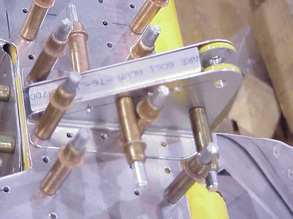
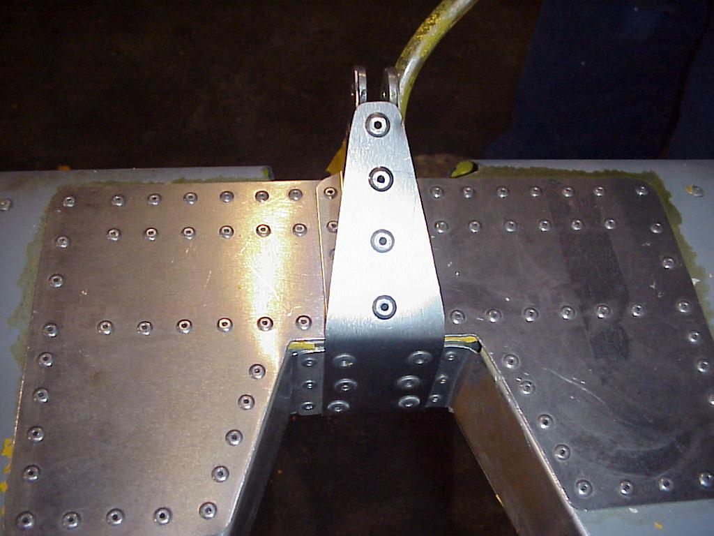
11 18) Cleco together. Put it back into the elevator assembly. 19) Close the skin and drill through the #40 holes from the Skin into the rib. Make sure the center line on the rib flange is visible through the pre-punched holes. 20) Cleco the Elevator Center Gussets (EL0451) into place, top and bottom. 21) Mark the Elevator Spar top and bottom flanges at the center where they must be trimmed for the Elevator Horn clearance. (Use the Skin as a guide). 22) Trim the Elevator Spar for the Elevator Horn. 23) Drill all new holes to #30. Remove the Elevator Skin and deburr. 24) Drill all the new holes in the Elevator Center Doubler and the new center ribs to #30. Bolt the two Elev/Rud Horns (EL0301) to the center of the Elevator. Remove parts and deburr. Reassemble. Figure Leave the center ribs and center gussets (EL0451) cleco d in place. 25) Locate EL0454 horn doublers. Locate the horn doublers one on each side of the elevator horn. Using a hole finder, transfer the holes that lie under the flanges of the horn doublers to their flanges. Drill #30 and cleco in place. Trace around elevator horn, remove horn doublers and trim. Drill out a #11 hole 1 below the ¼ hole that takes the cable bolt in both horns. Cleco one doubler back into place. Back drill the ¼ cable bolt hole and the #11 hole in the horn into the horn gusset. Repeat for the other doubler. Drill all holes in the center gussets (EL0451) out to #21. Slide EL0453 tube in between doublers and drill 5 equally spaced #21 holes through each doubler into side of tube. 26) Locate strap material EL0452. Trim to shape, as in Fig Slide this UNDER the tabs of the EL0450 s, and back drill the holes. Add two more holes between the existing ones. Drill out to #11. 27) Slide the strap out, cleco into place on top of the tabs, and mark for the bend lines. 28) Bend the strap to fit, cleco back into place. 29) Drill four equally spaced #11 holes through the strap into the tube. 30) Take assembly apart, deburr, and rivet together: EL0450 s and EL0303 s to skin with RV-1410; EL0450 center tabs and strap EL0452 with 6 X RV s and six RV01613 s; center doublers EL0451 with RV-1512 s. The #11 holes in the horns take an AN3-10A bolt and AN fibernut, with AN washers used to space out between the horns. Horn gussets to tube and center gusset with RV-1512 s; strap EL0452 to tube with RV-1613 s. Repeat above steps for the other side of the elevator. 10/08/2006 Page 11
12 10/08/2006 Page 12

13 Figure ) Cut out the Elevator Trim Skin along the tabs as in. Figure Figure ) Set aside the Trim Skin. NOTE: Be careful handling the Elevator Skin so you don t crease it. 10/08/2006 Page 13
14 33) Trim the tabs that remain on the Elevator Skin off lightly and file the edges. 34) Debur the Elevator Skin. 35) Chromate all mating surfaces. 36) Cleco the skin onto the Elevator Spar assembly. 37) Rivet together using 1/8 avex rivet (RV-1410). Rivet only one side of the skin at this time, you will need to have the skin open to install the servo wiring later. 38) Cut the center from the Elevator Skin and smooth the edges with a file. Figure Remove the inspection covers from the cut out and file smooth. Figure Trim Install 1) Trim the Front Trim Spar (EL0314) to fit between the two ribs at the trim location. 2) Trim a piece of Piano Hinge (1419 D00SS) ½ shorter than the Front Trim Spar. NOTE: Remove the hinge pin before cutting. Cut the hinge pin ¾ longer than hinge. 3) Mark the center of the hinge material. Mark the center of the Trim Tab space. 4) Position the hinge material under the Elevator Skin so the two center lines match up. Drill the #40 holes from the Elevator Skin into the hinge material. Figure /08/2006 Page 14
15 Figure ) Remove and debur the hinge. 6) Draw a line along the center of the top and bottom flanges of Front Elevator Trim Spar. 7) Position the Spar so the line is visible through the #40 holes in the Elevator skin. Drill the #40 holes into the Front Elevator Trim Spar. Cleco. 8) Drill the #40 holes on the bottom side of the Elevator Skin into the Front Elevator Trim Spar. 9) Remove the clecos on the top side and insert the Piano Hinge between the Front Elevator Trim Spar and Elevator Skin. Cleco. 10) Drill the #40 holes out to #30. 11) Remove the Front Elevator Trim Spar and Piano Hinge. 12) Debur and cleco the Front Trim Spar, Piano Hinge and Elevator Skin together. 13) Trim the Elevator Trim Skin as in Figure Figure ) Match skin to hinge and drill #40 holes about 5/16 of an inch in from ends where the two lines intersect. Figure /08/2006 Page 15
16 Figure ) Between these two holes drill #40 holes at approximately 1 ¼ spacing. 16) Connect the second half of the hinge to the first with the hinge pin. Center the Trim Skin in the gap and drill the #40 holes into the hinge from the Trim skin. Figure Figure ) Remove the Trim Skin. 18) Position the Trim Rear Spar (EL0315) as in Figure /08/2006 Page 16
17 Figure ) Drill the #40 holes from the Trim Skin into the Trim Rear Spar. 20) Insert the Piano Hinge between the Trim Skin and Trim Rear Spar. Cleco. 21) Using the Spar, mark a line where the skin will be trimmed. NOTE: Measure from the trailing edge to ensure that the line is square. 22) Remove the Spar and Piano Hinge. 23) Trim the skin along the line. 24) Mark a line, 5/16 in from the three edges on the bottom skin for the spar rivet holes. Drill a #40 hole where the lines intersect. 25) Between the two holes, along the line, drill #40 holes at an approximate spacing of 1 ½ Figure ) Cleco the Spar and hinge back onto the skin. Transfer the #40 holes from the skin into the spar clecoing as you go. Make sure Trim is flat. Fig /08/2006 Page 17
18 28) Disassemble and debur. Re-assemble with clecos. 29) Cut the trimmed piece of ribs from an earlier step so they fit between the spar and to the point where it does not distort the tailing edge. Do this for five ribs. NOTE: The flange direction of the middle rib is not important. 30) Using the same technique as you did in figure , make 90 degree flanges to pick up the trim tab spar. If this is not possible on all the offcuts, use a piece of angle(st0040) to make the flanges. 31) With the trim skin/spar assembly in place, transfer rivet lines from elevator skin to trim tab skin. These lines now set your rib positions. Remove tab and transfer lines to front of spar and lower surface of skin. Ensuring you will pick up rib flanges, drill three equally spaced #40 holes at each rib position on spar. 32) Draw lines down all flanges of trim tab ribs, centered or as appropriate. Back drill through the holes you drilled in the spar into the rib flanges, and cleco in place. 33) In the trim tab skin, drill #40 holes along traced lines at 11/8 11/4 spacing as appropriate. Cleco skin to spar/rib assembly. 34) Back drill through #40 holes in skin into ribs, using the lines drawn in step 5 as a guide. Open up all holes to #30, deburr and cleco together. Try to complete step 34 with the trim tab trailing edge clamped to the elevator trailing edge. 35) Connect the Trim to the Elevator with the Hinge Pin, if you have not already done so. 36) With the Elevator on its back, check to ensure that the Servo Backing Plate (EL0316) fits to the holes in the skin. (It also doubles as one inspection cover). 37) Position the Servo on the Servo Backing Plate so it will fit into the hole provided in the skin. Using the Servo, drill the four mounting holes. 38) Mount the Servo to the Servo Backing Plate with four Screws (AN R10), four washers (AN960-8) and four nuts (AN ). NOTE: Make sure that the Servo is pointing the right direction. 39) Locate Trim Horns EL1001. Place the trim horns back to back and rivet together with 7 RV-1410 rivets. Drill a #30 hole in the front top corner of the trim horns to accept the fork of the trim motor push/pull tube. 40) Mount the Trim Horns to the trim skin with fourteen 1/8 avex rivets (RV-1410). Position so it is in line with the Servo output shaft. Figure ) Drill out a small slot in the Elevator Skin for the Push-Pull rod to exit from the Servo. Enlarge as needed to allow full travel of the Servo. Any 12 volt battery will allow you to cycle the Servo through its distance. 42) Locate EL0032. Cut to length, fill with proseal, and slide over threaded push/pull tube to strengthen it. 10/08/2006 Page 18
19 NOTE: Final adjustments should be made when installing to the airplane. Before closing up the skin, route the Servo wiring back through a hole in the Elevator Front Spar (use grommet in hole to protect wiring). Run the wiring inside the Elevator Leading Edge Skin and exit through the Control Horn opening. 3.6 Tip Install 1) Position the Elevator Tip Skin (EL0408) to the Outboard Tip Rib and Inboard Tip Rib. Figure ) Drill #40 holes from the Elevator Tip Skin into the Tip Ribs keeping the ribs flush with the skin. Figure Figure ) Keeping the line visible through the #40 holes in the Elevator Tip Skin, transfer the holes into the Tip Ribs. Cleco. NOTE: It is expected that what you do to the top side, you will do to the bottom side at the same time. 4) Remove the Tip Skin. 5) Drill all #40 holes to #30. 6) Replace the Tip Skin and drill #40 holes to #30. 7) Disassemble the Tip. Debur all parts. 10/08/2006 Page 19
20 8) Chromate the mating surfaces of the Ribs, Spar and Elevator Skin and cleco. 9) Using the Tip Rib as a jig, draw out the shape of the Tip Rib on the EL0412 Raw Stock supplied. Cut out two large pieces and two small pieces. Cut one of the Elevator Tip Weights in half. Place a whole weight on a larger piece of EL0412 and a cut weight on a smaller piece of EL0412. Drill two 3/16 holes through the weights and plates. NOTE: You can use the 3/16 tooling hole on the ribs as the location for one of the holes. Locate and drill the second 3/16 hole through the rib. Figure and Figure Figure /08/2006 Page 20
21 10) Assemble the tip weights and backing plates to the ribs as per figures and ) Cleco the Tip Skin onto the Ribs. 12) Where the Tip skin overlaps the Spar and Elevator Skin, drill #30 holes at 1 spacing nominal. Figure Figure ) Disassemble and debur. 14) Chromate the mating surfaces and cleco. 15) Repeat steps for the other Elevator Tip. 16) Cleco the Inspection Covers in place. Drill the #40 holes to #30 and rivet to the Elevator Skin with 1/8 avex Rivets. NOTE: Stainless Steel screws or other suitable connectors can be substituted. For the Servo Backing Plate you can install floating anchor nuts for easy access. 17) Draw a line ½ from one edge of the Elevator Leading Edge. Pull the Leading Edge halves together with masking tape. The overlap should be a ½. Figure /08/2006 Page 21
22 Figure ) If you have installed the Servo wires you can now rivet the Elevator Skin with 1/8 rivets. 19) Drill holes along the Leading Edge to #30, using a 3 ¼ rivet spacing. Debur, chromate and rivet together using 1/8 (RV-1410) avex rivets. 10/08/2006 Page 22
2.1 Parts List Tool requirement Before you start assembling the Stabiliser Front Spar Center Doublers...
 Stabilizer Assembly 2.0 Exploded View...Error! Bookmark not defined. 2.1 Parts List...3 2.2 Tool requirement...5 2.3 Before you start assembling the Stabiliser...6 2.4 Front Spar...6 2.5 Center Doublers...7
ZODIAC 601 XL. Detail of outboard end. Full length recessed elevator trim tab. Detail of inboard end. Trim tab along left trailing edge of elevator.
 Full length recessed elevator trim tab. Detail of outboard end. Detail of inboard end. Trim tab along left trailing edge of elevator. Trim tab in neutral position 6-T-6 - Page 1 of 12 Drill out the middle
Section 6-T-3 Elevator
 Section 6-T-3 Elevator This manual has been prepared for assembly of the Elevator using match drilled parts. This photo assembly manual is intended as a supplement to the drawings. If there is any discrepancy
STOL CH H3-3SP Center Hinge Bracket. IMPORTANT: The Bracket 7H5-3SP is not symmetrical
 7H3-3SP Center Hinge Bracket IMPORTANT: The Bracket 7H5-3SP is not symmetrical Using a square helps layout and mark the perpendicular and the hinge hole. Note: Position of 1/4 hinge hole is 115.5mm from
Ch. 9.0 ELITE FUSELAGE ASSEMBLY 14/02/2003
 Fuselage Assembly In the front of the fuselage manual you will find an exploded view of the fuselage and a side view schematic. We suggest that you tape these to the wall of your workshop. Refer to them
11) Chromate the mating surfaces of the Leading edge Root Rib, Doubler and Root Rib Stiffeners. Rivet together with 1/8 rivets (RV-1410).
 Chromate the mating surfaces of the Leading edge Root Rib, Doubler and Root Rib Stiffeners. Rivet together with 1/8 rivets (RV-1410).") 11) Chromate the mating surfaces of the Leading edge Root Rib, Doubler and Root Rib Stiffeners. Rivet together with 1/8 rivets (RV-1410). 12) Chromate the Root Rib Attach Bracket and rivet to the Root
11) Chromate the mating surfaces of the Leading edge Root Rib, Doubler and Root Rib Stiffeners. Rivet together with 1/8 rivets (RV-1410). 12) Chromate the Root Rib Attach Bracket and rivet to the Root
Chap. 9.2 SR3500 Fuselage Assembly - Cabin. MODEL: SR Murphy Aircraft Mfg. Ltd. All rights reserved.
 26/06/2006 Page 1 26/06/2006 Page 2 26/06/2006 Page 3 Parts List for Gear Box No. Part Number Description Qty Required 1,23 FUS0711QL BRACING CHANNEL 2 2,22 FUS0711QR BRACING CHANNEL 2 3 FUS301QB CARRYTHROUGH
CENTER WING SECTION (CWS) WORK REPORT
 WORK REPORT") CENTER WING SECTION (CWS) WORK REPORT No. Check Parts / Description Qty PHASE 1: Preparations 1 [ ] 6V1-3 Rear ribs 2R & 2L 1 [ ] L Angle 6 2 [ ] 6V2-1 Rear Ribs.032 2R & 2L 2 [ ] 6V5-1 Gear Rib Doubler
CENTER WING SECTION (CWS) WORK REPORT No. Check Parts / Description Qty PHASE 1: Preparations 1 [ ] 6V1-3 Rear ribs 2R & 2L 1 [ ] L Angle 6 2 [ ] 6V2-1 Rear Ribs.032 2R & 2L 2 [ ] 6V5-1 Gear Rib Doubler
75-TA-4. Elevator Skins
 75-TA-4 This manual has been prepared for assembly of the. This photo assembly manual is intended as a supplement to the drawings. If there is any discrepancy between this manual and the drawings, the
WING ASSEMBLY 23.5 (Continued)
") A VERY IMPORTANT NOTE found on many wing drawings states Do not drill any unspecified holes into spar. This is extremely important as any extra holes may, under extreme conditions, WEAKEN THE SPAR. Note;
A VERY IMPORTANT NOTE found on many wing drawings states Do not drill any unspecified holes into spar. This is extremely important as any extra holes may, under extreme conditions, WEAKEN THE SPAR. Note;
Section 75-AA-1. Flaperon Assembly
 Section 75-AA-1 This manual has been prepared for assembly of the flaperons supplied with match drilled parts. This photo assembly manual is intended as a supplement to the drawings. If there is any discrepancy
Horizontal Stabilizer Service Bulletin
 Horizontal Stabilizer Service Bulletin Date: Friday November 19, 2004 To: All Super Rebel/Moose owners Re: Horizontal stabilizer tip rib INFO: A number of Super Rebels have shown cracking on the tip rib/rear
9.3 FUSELAGE ASSEMBLY 14/03/02
 9.3 MATING THE TAIL CONE TO THE CABIN 1) Trim the bottom flange of both FUS-339 side skins on the tailcone assembly as in Figure 1. 2) Remove the bottom two RBULK 2A s of bulkhead A on the tailcone. 3)
Section 75-ZA-2. Rudder Mounting
 Section 75-ZA-2 This manual has been prepared for installation of the Rudder. This photo assembly manual is intended as a supplement to the drawings. If there is any discrepancy between this manual and
Section 6-B-6, 6-B-7, & 6-B-8 Firewall Assembly
 Section 6-B-6, 6-B-7, & 6-B-8 Firewall Assembly This manual has been prepared for assembly of the firewall supplied with match drilled parts. This photo assembly manual is intended as a supplement to the
Cut the center and pre-drill the Hinge Plate. Do not drill the Rudder Hinge hole at this time.
 7F4-1 Upper Rudder Hinge Plate Layout the cut for the Upper Hinge Plate. Measure and mark the center for the Rudder Hinge. The center hinge hole is 75mm from the back edge of 7F4-1. Cut the center and
ZODIAC CH 601 Series Kit Aircraft
 ZODIAC CH 601 Series Kit Aircraft THE FOLLOWING IS A DRAFT MANUAL This manual has been written and published strictly for informational purpose. It has been prepared as a guide to facilitate the assembly
Section 75-FA-5. Firewall Assembly
 Section 75-FA-5 This manual has been prepared for assembly of the firewall supplied with match drilled parts. This photo assembly manual is intended as a supplement to the drawings. If there is any discrepancy
FORWARD FUSELAGE SIDES & REAR TOP SKINS
 FORWARD FUSELAGE SIDES & REAR TOP SKINS WORK REPORT Step No. Check Parts / Tools Qty Preparations. 1 [ ] 6F5-3 Upper Front Longerons 2 2 [ ] 6F5-5 Heel Support 1 3 [ ] 6F5-2 Front Floor Skin 1 3 [ ] Firewall
Photo-Guide (ZE & ZE )
") Photo-Guide (ZE-2009-05 & ZE-2009-07) The following photo-guide is for educational purposes only. It is intended to assist owners and/or aircraft mechanics with the installation of elements from from 6Z-1G
Photo-Guide (ZE-2009-05 & ZE-2009-07) The following photo-guide is for educational purposes only. It is intended to assist owners and/or aircraft mechanics with the installation of elements from from 6Z-1G
STOL CH 701. Layout the cut line along the bend tangent line on the web. 7V6-1 and 7V6-2SP
 Layout the cut line along the bend tangent line on the web. 7V6-1 and 7V6-2SP ORIENTATION: 90 degree flange is up Layout the bend line, 20mm from the end. Ref. bottom right diagram 7-V-6 Use a square to
ZODIAC CH 601 Series Kit Aircraft
 ZODIAC CH 601 Series Kit Aircraft THE FOLLOWING IS A DRAFT MANUAL This manual has been written and published strictly for informational purpose. It has been prepared as a guide to facilitate the assembly
REAR FUSELAGE ASSEMBLY
 SECTION 2 Rear Fuselage Bottom Assembly Ref Dwg 8FR-2 SECTION 2 - Page 1 of 17 FUSELAGE BOTTOM SKIN 8F2-3A Note: The edges of skin 8F2-3A are not a straight line. Check: edge distance from the center of
STOL CH 801 SECTION 2: Nose Rib 8R1-7
 SECTION 2: Nose Rib 8R1-7 Position the lower nose rib on the front of the spar at the predrilled holes just above rear rib #3 (615mm from the bottom of the spar) Check lateral alignment (rib is centered
Check the jig with the Slat Ribs. Notice the front tip is cut off, this will allow the slat to fit in the jig correctly.
 Slat Jig A slat jig will be needed to obtain the correct curvature of the slat. The Slat drawing is located on 7-F-13, cutout and trace on plywood. The length of the jig is 1830mm, which is the outboard
REVISION DESCRIPTION:
 REVISION DESCRIPTION: Page: 09-10 REV 1: Delete Step 1. 14401 Keil Road NE, Aurora, Oregon, USA 97002 PHONE 503-678-6545 FAX 503-678-6560 www.vansaircraft.com info@vansaircraft.com Service Letters and
STOL CH 701. Standard L ANGLES are supplied in 4ft length. Ref. bottom left diagram on drawing 7-V-2
 Standard L ANGLES are supplied in 4ft length. Ref. bottom left diagram on drawing 7-V-2 Length = 206mm. Layout the cut line on the outside flanges. Ref. see boxed diagram on drawing 7-V-2 Three vertical
Ford Pick Up Rear leaf Spring Kit Installation Instructions
 1948-1956 Ford Pick Up Rear leaf Spring Kit Installation Instructions 1-800-984-6259 www.totalcostinvolved.com Parts 48 inch leaf (2) springs (4) U-bolts 3/8-24 x l 1/4bolts (16) & nuts (2) 1/2-20 x 4
Page: REV 1: Step 5 and Figure 5 updated to better describe the potential necessity of modifying a rivet squeezer yoke.
 14401 Keil Road NE, Aurora, Oregon, USA 97002 PHONE 503-678-6545 FAX 503-678-6560 www.vansaircraft.com info@vansaircraft.com Service Letters and Bulletins: www.vansaircraft.com/public/service.htm REVISION
STOL CH 701. Clamp a reference extrusion on the bottom of the spar. Clamp the bottom flange of the rib to the extrusion. Rear Root Rib 7V4-2
 Rear Root Rib 7V4-2 Clamp a reference extrusion on the bottom of the spar. Clamp the bottom flange of the rib to the extrusion. Cleco the root nose rib to the spar Position the rear root rib at station
FLAPERON ASSEMBLY. Ref. Drawing 8XA-1 Exploded view SECTION 1 REAR SKIN AND NOSE RIBS ASSEMBLY
 Ref. Drawing 8XA-1 Exploded view SECTION 1 REAR SKIN AND NOSE RIBS ASSEMBLY The slope on the back side of each hinge bracket 8A1-5 face inboard towards the fuselage for both the left and right wing Work
Citabria Pro. Aerobatic Parkflyer. by Joel Dirnberger
 Citabria Pro Aerobatic Parkflyer by Joel Dirnberger Revision C: December 21, 2004 Citabria Pro Building Instructions Length: Wingspan: Wing Area: Flying Weight: Wing Loading: Functions: Specifications:
Page: REV 2: Added "Step 1: Straighten the W-0007B Rear Spar Reinforcement Fork as described on Page 10-03, Step 4."
 14401 Keil Road NE, Aurora, Oregon, USA 97002 PHONE 503-678-6545 FAX 503-678-6560 www.vansaircraft.com info@vansaircraft.com Service Letters and Bulletins: www.vansaircraft.com/public/service.htm REVISION
FORWARD FUSELAGE ASSEMBLY
 SECTION 2 Finishing the Firewall RIVETS: SA5 or A5 (all rivets on the firewall, rivet head set from the engine side) SUGGESTION: First drill undersize pilot hole #30 or #40, then open with #20 SECTION
Three vertical L angles must be riveted to each main spar (length = 206mm see boxed diagram on drawing 7-V-2).
.") Cut over-sized (left); Trim and file (above). Note: Six needed. Three vertical L angles must be riveted to each main spar (length = 206mm see boxed diagram on drawing 7-V-2). Trace line down center of
Cut over-sized (left); Trim and file (above). Note: Six needed. Three vertical L angles must be riveted to each main spar (length = 206mm see boxed diagram on drawing 7-V-2). Trace line down center of
Section C75-WA-1. Wing Skeleton
 Section C75-WA-1 This manual has been prepared for assembly of the wing skeleton supplied with match drilled parts. This photo assembly manual is intended as a supplement to the drawings. If there is any
ZODIAC CH650. ZODIAC CH 650 Series. Parts are labeled for easy identification with a part number and description:
 CH 650 Series Parts are labeled for easy identification with a part number and description: Part number example: 6T4-4 Vertical Tail Spar 6 - Zodiac CH 650 model T - Rudder section of the Aircraft drawings.
SERVICE BULLETIN
 SERVICE BULLETIN 14-02-03 Date Released: February 3, 2014 Date Effective: February 3, 2014 Subject: Affected Models: Required Action: Time of Compliance: Cracking in elevator spar web near elevator attach
`48-`56 Ford Pickup Rear leaf Spring Kit Installation Instructions Tech Line:
 `48-`56 Ford Pickup Rear leaf Spring Kit Installation Instructions Tech Line: 1-855-693-1259 www.totalcostinvolved.com CHECK ALL PARTS INCLUDED IN THIS KIT TO THE PARTS LIST BEFORE INSTALLING THE KIT.
ZODIAC 601 XL. ZODIAC CH 601 Series. Parts are labeled for easy identification with a part number and description:
 CH 601 Series Parts are labeled for easy identification with a part number and description: Part number example: 6T4-4 Vertical Tail Spar 6 - Zodiac CH 601 model T - Rudder section of the Aircraft drawings.
SERVICE BULLETIN
 SERVICE BULLETIN 16-03-28 Date Released: May 6, 2016 (Initial Release) June 2, 2016 (Added Note, pg.11) Date Effective: May 6, 2016 Affected Models: Subject: Required Action: All RV-3, 4, 6/6A, 7/7A, 8/8A,
Pre-Paint>Wings>Fit ailerons. Objectives of this task: Materials and equipment required: Size the ailerons and pre-mould strips
 Pre-Paint>Wings>Fit ailerons Objectives of this task: In this task the ailerons and the pre-mould strips will be sized and trimmed, then flocked onto the wings and glassed in place, and the next day the
SPUNKY ASSEMBLY MANUAL
 SPUNKY ASSEMBLY MANUAL Please read the tips section at the back of this manual regarding the use of laser cut parts. The proper removal and preparation of these parts is important. When laser cut, some
STANDARD CANOPY WORK REPORT B-1
 STANDARD CANOPY WORK REPORT B-1 No. Check Parts / Tools Qty _ Canopy Lock 1 [ ] 6E2-3 Canopy Hinge Block 1 2 [ ] 6E4-5 Canopy Side Frame 2 2 [ ] 6E2-1 Canopy Lock Assembly 1L + 1R 3 [ ] 6E2-4 Rear Lock
Hobby Lobby Zip Supplementary instructions Please refer to the included drawings while using these assembly instructions
 Materials needed: 15 or 30 minute epoxy Medium CA Masking tape Scotch tape Servo Tape Wax paper Tools Needed: Pencil or marker Flat building surface Hobby knife or razor blade 7/64" or 3mm drill bit 3/16"
Metal Aircraft Landing Light Installation Instructions
 Metal Aircraft Landing Light Installation Instructions This landing light kit was designed for the Thorp T-18 as a method of installing a halogen landing light in the leading edge of the outer bay of the
Flaperon Assembly Manual
 Flaperon Assembly Manual for PegaStol Aftermarket Wings A Senior Project presented to The Faculty of the Aerospace Engineering Department California Polytechnic State University, San Luis Obispo In Partial
Note - the nose ribs and are thinner than the main ribs. These nose ribs will use a thinner rib cap than the ribs. This is per design.
 Stabilizer rev 1.2 The SE5a stabilizer is the heartbeat of the tail and is recreated like the full scale version. All tail pieces depend on the stabilizer. It uses the steel fittings, pulleys, inspection
FUSELAGE CONSTRUCTION
 FUSELAGE CONSTRUCTION Note: prior to building and gluing on the work surface use protective covering on your building surface. (wax paper or clear wrap) Fit the laser cut Fuselage Front and Fuselage Rear
ZODIAC CH 601 Series Kit Aircraft
 ZODIAC CH 601 Series Kit Aircraft THE FOLLOWING IS A DRAFT MANUAL This manual has been written and published strictly for informational purpose. It has been prepared as a guide to facilitate the assembly
SERVICE BULLETIN
 14401 Keil Road NE, Aurora, Oregon, USA 97002 PHONE 503-678-6545 FAX 503-678-6560 www.vansaircraft.com info@vansaircraft.com Service Letters and Bulletins: www.vansaircraft.com/public/service.htm SERVICE
WING ASSEMBLY SECTION 4. Mounting Wing Ribs to Main Spar. 1. Identify the proper locations for those ribs with attachment brackets.
 WING ASSEMBLY SECTION 4 Mounting Wing Ribs to Main Spar Compass Check 1. Identify the proper locations for those ribs with attachment brackets. 2. Position and drill the nose ribs. 3. Un-cleco the nose
Kwik-Lock. Installation Instructions. Attention Dealers: Please give this owners manual to the customer when the product is delivered.
 Serving the Truck & Trailer Industry Since 1944 Installation Instructions Attention Dealers: Please give this owners manual to the customer when the product is delivered. Call 800-535-9545 www.aeroindustries.com
77.5 degrees REAR CHANNEL PLYWOOD TEMPLATE
 77.5 degrees REAR CHANNEL PLYWOOD TEMPLATE Ref. 6-B-14 Make following template: Vertical distance = 300mm Layout dimensions shown in the bottom right table on drawing 6-B-14 Top and bottom are square to
Section 75-SA-1 Slat Section
 Section 75-SA-1 Slat Section This manual has been prepared for assembly of the slat sections supplied with match drilled parts. This photo assembly manual is intended as a supplement to the drawings. If
ZODIAC 601 XL. REAR RIBS 6W6-1 to 6W6-9. Reference to drawing 6-W-00 for orientations of ribs flanges. Rear ribs are tapered: rib #9 is the shortest.
 REAR RIBS 6W6-1 to 6W6-9 Reference to drawing 6-W-00 for orientations of ribs flanges. Rear ribs are tapered: rib #9 is the shortest. Right wing Zodiac CH 6-W-6 - Page 1 of 12 Burr on edge of flanged lightening
Section 6-B-4 Rear Fuselage Riveting
 Section 6-B-4 Rear Fuselage Riveting This manual has been prepared for assembly of the rear fuselage. This photo assembly manual is intended as a supplement to the drawings. If there is any discrepancy
Zodiac CH 601 XL drawing revision log, updates included in 4 th Edition, January 1, 2008.
 Zodiac CH 601 XL drawing revision log, updates included in 4 th Edition, January 1, 2008. 6-X-0 6-X-1 6-T-0 6-T-1 6-T-2 6-T-3 6-T-4 6-T-5 6-T-6 6-W-0 6-W-00 6-W-1 6-W-2 6-W-3 6-W-4 6-W-5 6-W-6 01/08 DRAWING
STC GROUP LLC 480 RUDDIMAN DRIVE MUSKEGON, MICHIGAN REPORT NO: G REV E TRIO AUTO PILOT INSTALLATION INSTRUCTIONS
 STC GROUP LLC 480 RUDDIMAN DRIVE MUSKEGON, MICHIGAN 49445 REPORT NO: G-1006-51 REV E TRIO AUTO PILOT INSTALLATION INSTRUCTIONS CESSNA MODEL 182 WITH PREVIOUS CESSNA EQUIPPED AUTO PILOT DATE: Original Issue
After the canopy hinge is square with the firewall and the nut plates are installed you can set up the hinge mounts. Start by clamping a 1/16 tongue
 Written by: Sean Cole September 19, 2008 When fitting the stiffener use 3/32 clecos to hold it in place, it makes a smaller hole and is easier to work with. Only use the amount needed to hold the stiffener
12. Wings, Flaps, Ailerons and Struts
 12. Wings, Flaps, Ailerons and Struts Fit Aileron Hinges Reference: Drawing 20270K2 Photo 12.1 Parts Required: 2007092 Aileron LS 200809N Aileron RS 2001394 Hinge 3/16 A1 (4) 2001694 Hinge Pin (4) PH0059N
Precision Steel Car s 100 T Steel Coil Car
 Precision Steel Car s 100 T Steel Coil Car Precision Steel Car www.precisionsteelcar.com info@precisionsteelcar.com Paul Vernon: (513) 571-5739 Revised 4/30/2009 Contents of Kit Main Tube Side Frame 2
Classic Roll Tarp. Installation Instructions. Attention Dealers: Please give this owners manual to the customer when the product is delivered.
 Serving the Truck & Trailer Industry Since 1944 Classic Roll Tarp Attention Dealers: Please give this owners manual to the customer when the product is delivered. Call 800-535-9545 www.aeroindustries.com
STC GROUP LLC Page Ruddiman Drive PA-28 & PA-32 Trio Pro Pilot Installation Instructions North Muskegon, Michigan 49445
 STC GROUP LLC Page 1 STC GROUP LLC 480 RUDDIMAN DRIVE MUSKEGON, MICHIGAN 49445 DOCUMENT NO: 1028001 REVISION D TRIO PRO PILOT INSTALLATION INSTRUCTIONS PIPER AIRCRAFT CORPORATION PA-28 AND PA-32 DATE:
Classic Roll Tarp. Installation Instructions. Attention Dealers: Please give this owners manual to the customer when the product is delivered.
 Serving the Truck & Trailer Industry Since 1944 Classic Roll Tarp Attention Dealers: Please give this owners manual to the customer when the product is delivered. Call 800-535-9545 www.aeroindustries.com
Installation Instructions
 DODGE 16K Industry Standard Rail Custom Mounting Kit #2728 Gross Trailer Weight (Maximum)...16,000 lbs. Vertical Load Weight (Max. Pin Weight)...4,000 lbs. SYSTEM TOW CAPACITY Please note, in order to
RESolution V2 Manual
 RESolution V2 Manual Note for the German Manual: Yellow Bottle thick CA Pink Bottle Med CA Blue tube 5 minute Epoxy Green tube 90 Minute Epoxy Construction of the Fuselage Step 1: Cover the plan with a
TOOL LIST FOR TAILGATE HIDDEN LATCH & LINK ASSY FOR FORD FLARESIDE TRUCKS
 TOOL LIST FOR TAILGATE HIDDEN LATCH & LINK ASSY FOR 53-87 FORD FLARESIDE TRUCKS Vise Grip Clamps C-clamps Sharpie Marker Ball Peen Hammer Center Punch 3/8 or 1/2 Drill 5/32, 7/32, 9/32, and 3/8 Drill Bits
Warnings. Description. Prior to Installation Tools Needed
 Warnings Failure to act in accordance with the following may result in death or personal injury. The JT Strong Arm Stabilizer System is intended to eliminate chassis movement in travel trailers and fifth
FINAL ASSEMBLY- DOORS
 - DOORS DRAWING 8XF-5 ASSEMBLY OF THE DOORS CONTENTS SECTIONS #4a DOOR FRAME #4b DOOR GUSSETS & BOTTOM SKIN #4c DOOR LATCH & STOP Helpful building tips: Use a flat, unwrapped piece of plywood for the door
ZODIAC 601 XL UPRIGHT CHANNELS 6B5-6. Top and bottom outboard flange is joggle to overlap the.093 extrusion 6B2-3 and 6B11-1
 UPRIGHT CHANNELS 6B5-6 Top and bottom outboard flange is joggle to overlap the.093 extrusion 6B2-3 and 6B11-1 Length: fits between the bottom and top longerons. Clamp the upright channel to the rear frame
Super Sky Surfer 2000 Assembly Instructions
 Super Sky Surfer 2000 Assembly Instructions Note: Plug and Play version of the Sky Surfer comes with fuselage pre-glued and motor/servos installed. If you wish to route antennas or wires through the tail,
JAMISON SPECIAL. Building Guide
 JAMISON SPECIAL Building Guide WING Mark then drill holes for wing jig rods. Slide Ribs onto jig rods Mark the rib positions on 1/16 x 1 trailing edge, 1/4 x 1/4 leading edge & 1/4 x 1/4 spars Pin ribs
THE APOGEE A 100-INCH AMA DURATION SAILPLANE FROM DYNAFLITE
 THE APOGEE A 100-INCH AMA DURATION SAILPLANE FROM DYNAFLITE Apogee is the intermediate sailplane designed to be competitive in AMA duration contests. Effective spoilers, rudder and full flying stabilizer
Assembly Instructions 10 X 10 Aluminum Frame Building
 Assembly Instructions 10 X 10 Aluminum Frame Building 27 97 9 8 47 36 74 52 10 10 X 10 Square Building W/ Dome Includes: The Steel Entry Door with a Dead Bolt Lock assembly and Aluminum Door Frame. Metal
RH-412 STEEL DOORS INSTALLATION INSTRUCTIONS
 RH-412 STEEL DOORS INSTALLATION INSTRUCTIONS By following the steps outlined below, the assembly, installation and adjustment of the steel doors, will be a simple process. Let s start with the Driver Side.
LANDING GEAR. 1. Fit landing gear into slots on bottom of fuselage.
 LANDING GEAR 1. Fit landing gear into slots on bottom of fuselage. 4. Use channel-lock pliers to press blind nuts into position (note: drilled hole should be slightly smaller than shaft of blind nut for
ED1300/1300F SERIES CONCEALED VERTICAL ROD DEVICE INSTALLATION INSTRUCTIONS
 ED1300/1300F SERIES CONCEALED VERTICAL ROD DEVICE INSTALLATION INSTRUCTIONS Ver.2 1300 SERIES CONCEALED VERTICAL ROD DEVICE Top Strike Latch Screws Strike Screws Release Plunger Top Latch Plunger Screws
INSTALLATION INSTRUCTIONS RH 412 STEEL DOORS
 By following the steps outlined below, the assembly, installation and adjustment of the steel doors, will be a simple process. Let s start with the Driver Side. Note: Having the hood open makes the job
6625 WEST WILSHIRE BLVD. OKLAHOMA CITY, OK (405) FAX (405)
 FAX (405)") INSTALLATION INSTRUCTIONS FOR THE TAILGATE WITH LATCH AND LINK ASSEMBLY 76-87 FORD SHORT & 53-87 FORD LONG FLARESIDES 1. Assemble the bed and make sure the box is square. Measure the distance between the
INSTALLATION INSTRUCTIONS FOR THE TAILGATE WITH LATCH AND LINK ASSEMBLY 76-87 FORD SHORT & 53-87 FORD LONG FLARESIDES 1. Assemble the bed and make sure the box is square. Measure the distance between the
T-15 EDF INSTRUCTION MANUAL. Wingspan.31in. Weight..2.5 lb. EDF...70mm 12 Blade ToughJets, LLC Kittery, ME Page 1 of 22.
 TM T-15 EDF INSTRUCTION MANUAL Specifications Wingspan.31in Length..41.75in Wing Area 515 sq in EDF...70mm 12 Blade Weight..2.5 lb Radio...3 channel Motor...Brushless Battery 14.8v 2200mah 40c 2013 ToughJets,
10. Wing prep and subassembly
 Date Section Objective: Construct and fabricate the sub-assemblies of the wing panel. Required Parts: Wing left 11gal PN104-300, Wing right 1gal PN104-400, Wing left 15 gal option PN104-322, Wing right
C-180 Builder s Manual
 C-180 Builder s Manual. May 20, 2002 Last revised July 11, 2002 Copyright! 2002 Douglas Binder, Mountain Models www.mountainmodels.com sales@mountainmodels.com (719) 630-3186 1 Required Equipment! Xacto
INSTALLATION MANUAL IOWA MOLD TOOLING CO., INC. BOX 189, GARNER, IA MANUAL PART NUMBER:
 PARTS-1 Model 24562/28562 Crane INSTALLATION MANUAL IOWA MOLD TOOLING CO., INC. BOX 189, GARNER, IA 50438-0189 641-923-3711 MANUAL PART NUMBER: 99903701 Iowa Mold Tooling Co., Inc. is an Oshkosh Truck
HANDLING AND ASSEMBLY INSTRUCTIONS FOR TRUE FOCUS 3.0M, 3.8M AND 4.2M ANTENNAS WITH POLAR MOUNT
 HANDLING AND ASSEMBLY INSTRUCTIONS FOR TRUE FOCUS 3.0M, 3.8M AND 4.2M ANTENNAS WITH POLAR MOUNT Introduction SECTION 1 Thank you for purchasing one of our fine True Focus products. This manual covers the
4. Bevel the LE face of HS1-HS11 to match the horizontal stab leading edge sweep angle.
 BEFORE YOU BUILD 1. Unroll each sheet of the plans. Roll them inside out so that they will lie flat on the building surface. 2. Assemble the tools that you will need to build each section so that they
Building a Giant Scale Electric EINDECKER Part 2
 Building a Giant Scale Electric EINDECKER Part 2 John Bernard N1KUB AMA 58903 IMAA 28971 In Part-1 of this series, we explored the 100 Eindecker kit from SR Batteries and started building the fuselage.
SECTION 11: EMPENNAGE ATTACHMENT
 TILCONE V-STB VS-1204 FWD SKIN SECTION 11: EMPENNGE TTCHMENT RUDDER STBILTOR RIGHT ST LEFT ST DTE OF COMPLETION: PRTICIPNTS: 09/25/08 0 RV-12 DTE: REVISION: PGE 11-01 Step 1: Remove the VS-1204 Fwd Skin,
STOL CH F2-2 Side Skin
 7F2-2 Side Skin IMPORTANT: See drawing 7F2-2 to identify the topside of the skin, also clearly mark the side that will be on the inside of the fuselage (if possible choose the side with the manufacture
SZD-10 bis CZAPLA ASSEMBLY MANUAL IN PICTURES
 1 RUDDER Plan and parts: 2 Assembly steps: Photo above: glue together rudder spar, ribs and trailing edge. Clamp spar to a flat surface (chipboard on the photo) and make sure the straight aligment of the
CHEVY SuperBracket Mounting Kit #0826
 CHEVY SuperBracket Mounting Kit #0826 #1200 SuperGlide (16K) #0800 SuperGlide (20.5K) Gross Trailer Weight (Maximum) Vertical Load Weight (Max. Pin Weight) 16,000 lbs. 4,000 lbs. Gross Trailer Weight (Maximum)
Bend-Tech Dragon Assembly Manual
 p.1 Bend-Tech Dragon Assembly Manual IMPORTANT: Please read before unpacking. Place shipping container in a wide open area where you will have room to work and assemble this product. Shipping The Dragon
INSTALLATION INSTRUCTIONS
 INSTALLATION INSTRUCTIONS HIGH PRESSUE LAMINATE (HPL) TOILET PARTITIONS 1030 TrimLineSeries 1040 DesignerSeries Includes continuous hardware option.65. IMPORTANT: Storage and Handling Information on last
RSM DISTRIBUTION Presents
 RSM DISTRIBUTION Presents MOSQUITO By Jack Sheeks Photo _ Jack Sheeks Semi Scale Twin Stunter Wing Span: 58" Length: 37-3/4 Area: 579 sq. in. Engine: Two.35 -.40 www.rsmdistribution.com Call (951) 678
Pre-Paint>Fuselage>Empennage>Fit elevator. Objectives of this task: Materials required: Prepare the horizontal stabiliser and the elevator
 Pre-Paint>Fuselage>Empennage>Fit elevator Objectives of this task: To fit the elevator to the horizontal stabiliser, to fit the trim tabs to the elevator and the end caps to the elevator and the horizontal
YJ DeFenders. These installation instructions apply to the following Poison Spyder products:
 INSTALLATION INSTRUCTIONS INST-13-02-070_A YJ DeFenders IMPORTANT: Thank you for purchasing this Poison Spyder product. Please read through this entire document before proceeding with installation. If
FLITZEBOGEN-2 Assembly instructions
 FLITZEBOGEN-2 Assembly instructions Trim the end of the fuselage to the length of 925mm from the nose. Be careful to avoid splitting the carbon fibers. Sand the base of the stab mount in preparation for
INSTALLATION INSTRUCTIONS
 INSTALLATION INSTRUCTIONS SOLID PHENOLIC TOILET PARTITIONS 1080 DuraLine Series 1180 DuraLine Series Class-A Fire Rated IMPORTANT: Review these instructions thoroughly prior to installation. FLOOR ANCHORED
CUT OUT FLARES INSTALLATION INSTRUCTIONS FOR 20017, 20018, F100-F150 F250-F350 P.U. & BRONCO CUT OUTS
 20017 04/22/03 REV-A CUT OUT FLARES INSTALLATION INSTRUCTIONS FOR 20017, 20018, F100-F150 F250-F350 P.U. & BRONCO CUT OUTS Tools Required for Installation: (A) 3/16 Drill Bit (B) Pop-Rivet Gun (C) Air
SE5a Wing Panels rev 1.0
 SE5a Wing Panels rev 1.0 The top and bottom wings are different. They might look the same but the bottom wing has one less rib and some rib spacing difference. This is due to where the wooden interplane