To Purchase This Item, Visit BMI Gaming (800)
|
|
|
- Sherilyn Adams
- 5 years ago
- Views:
Transcription

1
2

3

4
5


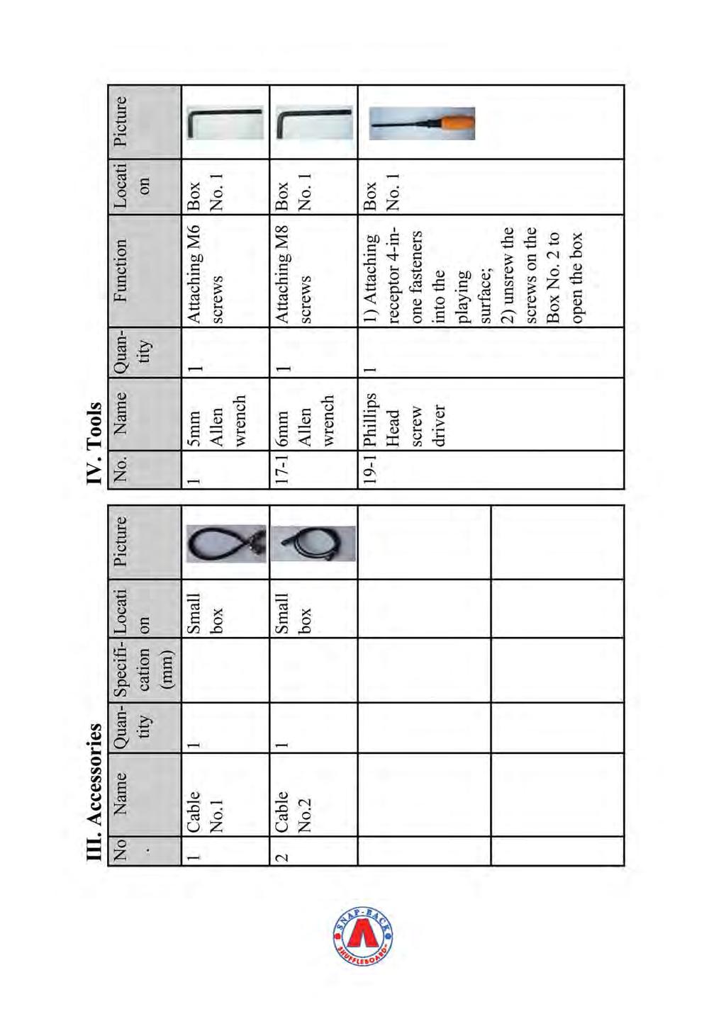
6 How to install 1. Connect the blocker with the motor box and the pivot box and fasten them with the screws. 2. Insert cable No.1 into the connector at the bottom of the motor box. 3. Position the two side ramps away from the rear of the table to enable installation of the blocking system. The attaching screws at the bottom of the cradle should be removed for this step. 4. Let the cable pass through the hole at the bottom of the cradle. Then insert the blocking system just in front of the rear of the cradle. 5. Insert the pins of the pivot box into the positioning hole in the cradle and fasten both the motor box and the pivot box to the cradle with screws.


7 6. And then move the ramps toward the rear of the table until they are next to the blocking system and tighten them with screws. 7. Insert the other end of cable No.1 into the socket next to the power box. 8. Install the cash box holder between the two front legs by using the bolts to attach the holder. The front wood shelf which comes with the Summit model Snap-Back Shuffleboard table will not be used with the coin operation system, so you may choose to discard it or store it.


8 9. Open the cash box, lift it up and attach it to the holder by using the bolts. Tighten the bolts with the Allen Wrench to make sure the cash box is tightly attached to the holder. Then fasten the screws on the top. Close the door. 10. Insert cable No.2 into the connector on the cash box, and the other end into the socket near the red button box (left side, under cradle).
 03 Minimum payment for more")
 For most")

9 11. Turn on the power Default Settings: 01 Price to start game: $ Playing time for game start: 15 minutes (900 seconds) 03 Minimum payment for more playing time: $ Additional playing time for minimum payment: 5 minutes (300 seconds) For most situations, the default settings will be satisfactory, and you should be able to start immediately by using them. However, if you prefer to modify the cost of play, or the playing time allowed, you can modify the default amounts by changing the Function Settings, as follows:
10 Function Settings: Open the back of the scoreboard and push the button on the left side to keep the lights on during this process. The function settings are modified by pushing the buttons on the back of the electronic board inside the scoreboard case. 1. Press PRO for 3 seconds to enter Programming Mode. 2. To set the price required to start play(function 01), press + to select functional code 01, which will be shown on the red LEDs at the front of scoreboard. 3. Press SET for 1.5 seconds. The right digit of the yellow light flashes. 4. Press + or - to adjust the amount of money needed to start the game. You can push "+" repeatedly until you reach the total amount, or you can push "+" until this digit is OK, then press "set" quickly to move to the next digit. That digit is set by pushing "+" or "-" until the correct number is shown, then the next digit can be set by pressing "set" quickly. When you finish setting the amount, press SET for 1.5 seconds to save the settings. 5. Apply the same procedures to function 02, 03 and 04. Note that all times (function 02 and 04) must be entered in seconds. For example, each minute must be entered as 60 seconds, so 5 minutes must be entered as 300 seconds.
11 Other Notes: 1. If more function settings are required, please contact Mega Mania Diversions, LLC for further information. 2. If no operation is executed within 1minute, the system will go back to the normal setting automatically.

12
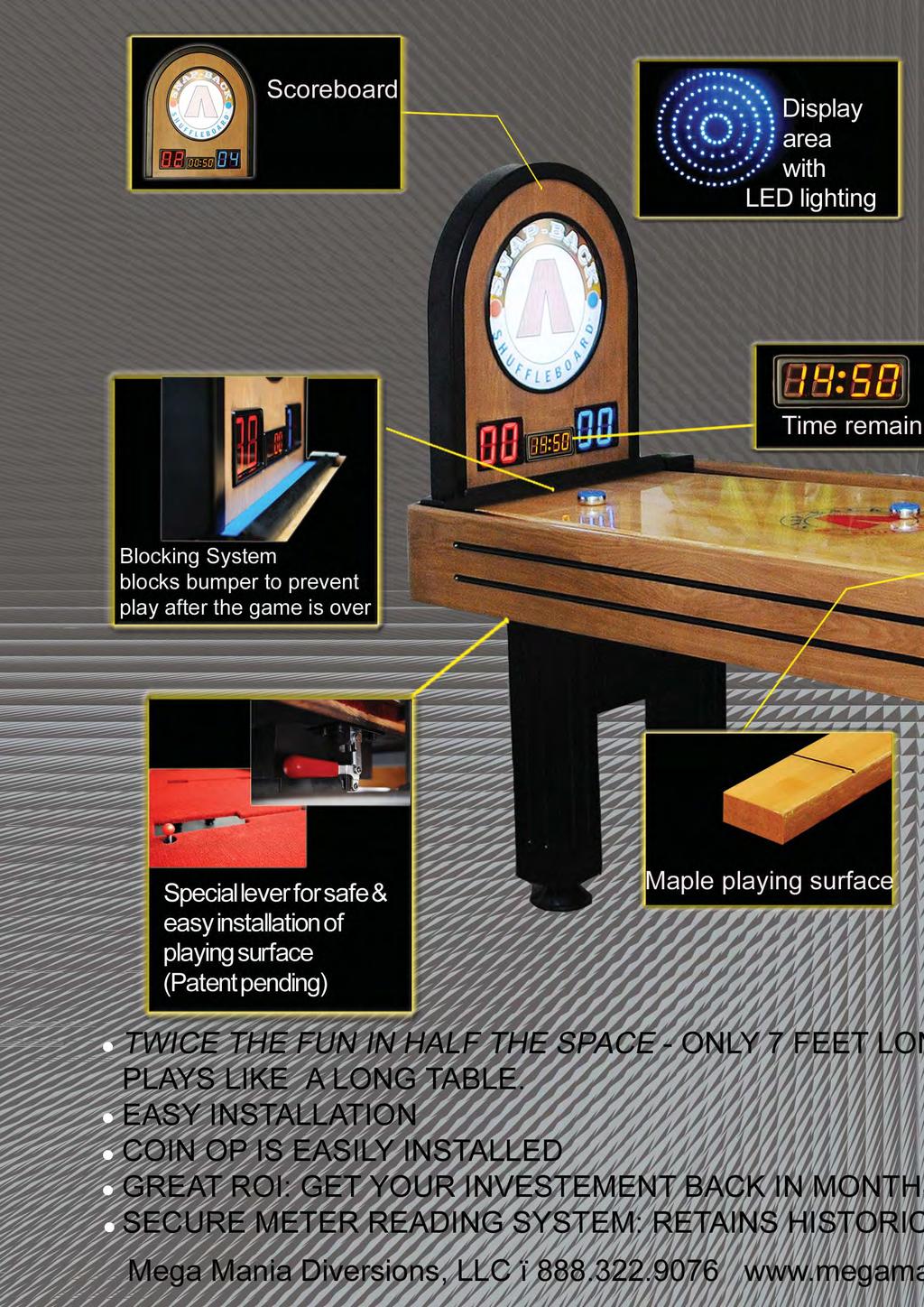
Users Manual TAVERN MODEL TWICE THE FUN IN HALF THE SPACE
 Users Manual TAVERN MODEL TWICE THE FUN IN HALF THE SPACE ASSEMBLY INSTRUCTIONS Congratulations on your purchase of a fine Snap Back Shuffleboard! To make it as easy as possible to assemble your table,
Mod-E Pro Electric L-Shaped Standing Desk
 The Height of Healthy Design Mod-E Pro Electric L-Shaped Standing Desk ASSEMBLY AND OPERATION MultiTable Mod-E Pro Electric L-Shaped Table Base PARTS AND TOOLS PLEASE REVIEW these instructions before beginning
MultiTable Mod-E 2 Electric Standing Desk
 The Height of Healthy Design MultiTable Mod-E 2 Electric Standing Desk ASSEMBLY INSTRUCTIONS MultiTable Mod-E 2 Electric Standing Desk Frame PARTS AND TOOLS PLEASE REVIEW these instructions before beginning
Arc Trainer Main Frame Assembly
 Arc Trainer Main Frame Assembly Kit No. 610AK019-4 Kit No. 630AK019-4 NOTE: This instruction sheet describes how to replace the main frame assembly in the Arc Trainer 610A. Tools Required 3/16 Allen wrench
Barnside Pantry IMPORTANT NOTE Carefully remove all the parts from the carton and put them individually on a soft cloth to prevent scratch
 88 5516 653 Barnside Pantry IMPORTANT NOTE Carefully remove all the parts from the carton and put them individually on a soft cloth to prevent scratches or other damage occurring to the parts. We have
Jenny Legs Assembly Instructions
 Jenny Legs Assembly Instructions R EXTENDED PHILLIPS BIT MM ALLEN WRENCH 6MM HEX DRIVE /" 007 Steelcase Inc. Grand Rapids, MI 90 U.S.A. Printed in U.S.A. Page of 6 88000 Rev F Jenny Club Instructions:
Hover. Installation Instructions. Raised Panel. Version
 Installation Instructions Version 8-2-17 Raised Panel Table of Contents Page Raised Panel Trough 3-13 Platform Trough 14-20 Platform 120 Degree Trough 21-24 Electrical 25-28 Type A Electric Bases 29-31
Rotary Fixture M/V/X CLASS LASER SYSTEMS. Installation and Operation Instructions
 Rotary Fixture M/V/X CLASS LASER SYSTEMS Installation and Operation Instructions 02/01/2000 Introduction The Rotary Fixture controls in the Printer Driver are used along with the optional Rotary Fixture
Assembly Instructions. Table of Contents
 HQ Little Foot Assembly Instructions Back of Handi Quilter, Inc. 501 North 400 West North Salt Lake, UT 84054 1-877-697-8458 Front of 2015 Handi Quilter, Inc. www.handiquilter.com Printed in the United
Ready To Go SimpleSpec tm. Installation Manual. For more information, please visit 3-form.com or call
 Contents Overview ( 1) 3/8" Varia Panel = Cable Tensioner with Cover Plate KIT Stainless Steel: 3-15-1636-K Black Oxide: 3-15-2005-K Cable Tensioner with Cover Plate SS: 3-15-1636 BO: 3-15-2005 + M8 Thread
PFD-22 Top OHC Patch Fitting & PFD-10 Bottom Patch Fitting Installation Instructions
 Top OHC Patch Fitting & Bottom Patch Fitting Installation Instructions For Installation Assistance, Call 855.594.6989 www.assaabloyglass.us Tools Needed: Torque Wrench and Bit 5mm Allen Wrench 6 7 /16"
mila-wall (Series100) General Operating Instructions page 1 of 15
 General Operating Instructions page 1 of 15") mila-wall (Series100) General Operating Instructions page 1 of 15 Step #1: Before setting up walls, lower adjustable leveling feet on each panel approximately 1". This will allow access to the threaded
mila-wall (Series100) General Operating Instructions page 1 of 15 Step #1: Before setting up walls, lower adjustable leveling feet on each panel approximately 1". This will allow access to the threaded
M. Door 1 Pc. 1 Pc. Door 1 Pc. 1 Pc. M3x20 Wood Screw (long) 8 Pcs. (+1 extra) M3x10 Wood Screw for Magnet 8 Pcs. (+1 extra)
 8 Pcs. (+1 extra) M3x10 Wood Screw for Magnet 8 Pcs. (+1 extra)") 88 5516 653 Barnside Pantry IMPORTANT NOTE Carefully remove all the parts from the carton and put them individually on a soft cloth to prevent scratches or other damage occurring to the parts. We have
88 5516 653 Barnside Pantry IMPORTANT NOTE Carefully remove all the parts from the carton and put them individually on a soft cloth to prevent scratches or other damage occurring to the parts. We have
WARNING!! DO NOT LIFT DOORS UP WHEN THE HOOD IS OPEN. THE DOORS WILL HIT THE HOOD!
 WARNING!! DO NOT LIFT DOORS UP WHEN THE HOOD IS OPEN. THE DOORS WILL HIT THE HOOD! THIS KIT INCLUDES: 4 M8-1.25X30MM BOLTS WITH WASHERS 12 M8-1.25X40MM BOLTS WITH WASHERS 2 SHOULDER BOLTS WITH RIGHT AND
Homestead Bar Cabinet IMPORTANT NOTE Carefully remove all the parts from the carton and put them individually on a soft cloth to prevent s
 88 5527 991 Homestead Bar Cabinet IMPRTANT NTE Carefully remove all the parts from the carton and put them individually on a soft cloth to prevent scratches or other damages occuring to the wood parts.
This procedure will cover the steps to properly pack up the ARES for shipment.
 TA Instruments Packing the ARES Instrument This procedure will cover the steps to properly pack up the ARES for shipment. Packing Materials Provided: Standard LS Shipping carton Shipping carton Shelf for
Motorized or Crank Operated Fortress Zipper Track Shade with Housing and Side Track Installation Instructions
 Motorized or Crank Operated Fortress Zipper Track Shade with Housing and Side Track Installation Instructions Tools Needed Drill 3/8 Metal Drill Bit ¼ Masonry Drill Bit Measuring Tape Pencil 4 Level Phillips
meped v2 Assembly Manual
 meped v Assembly Manual The meped is an open source quadruped robot designed by Scott Pierce of Spierce Technologies, LLC. This design is released under the Creative Commons, By Attribution, Share Alike
TRIUMPH-LX ELECTRIC TABLE BASE
 TRIUMPH-LX ELECTRIC TABLE BASE 2T-LX Rev A 7/17 Model 2T-LX-C28-24- Model 2T-LX-C28-30- Model 2T-LX-C40-24- Model 2T-LX-C40-30- = SLV, BLK or WHT ASSEMBLY AND OPERATION TRIUMPH-LX 2 LEG ELECTRIC TABLE
FLAT PANEL CART WITH OR WITHOUT A PULL OUT SHELF
 FP42UL FP60UL FP42MUL FP60MUL FLAT PANEL CART WITH OR WITHOUT A PULL OUT SHELF WARNING: FP42 carts are intended to hold monitors up to 75 lbs and FP60 carts are intended to hold monitors up to 100 lbs.
Colonial Classic Bar
 88 5528 991 Colonial Classic Bar IMPORTANT NOTE Carefully remove all the parts from the carton and put them individually on a soft cloth to prevent scratches or other damages occuring to the wood parts.
BY ALIEN TECHNOLOGIES CORP
 BY ALIEN TECHNOLOGIES CORP Assembly Instructions TopLift Pros YOU MAY ALSO REVIEW OUR ASSEMBLY VIDEO, PLAY AND PAUSE AT YOUR CONVENIENCE. JUST VISIT US AT WWW.TOPLIFTPROS.COM AND GO TO Customer Support
User Instructions Multiline Otter Scoreboard Caddy Assembly
 List of parts: User Instructions Multiline Otter Scoreboard Caddy Assembly Single Caddy Double Caddy 1 1 Base assembly with attached wheels 2 4 1 1 2 4 4 8 10 20 12 Uprights (60 or 74 aluminum extrusion)
CNC Router Parts PRO Machine Kit Cable Track Installation Instructions
 1 1 X CABLE TRACK TRAYS & BRACKETS The cable track on the side of the system is supported by a metal tray (or multiple trays for longer systems such as a PRO4896). These trays hang from brackets on the
Pedestal Desk IMPORTANT NOTE Carefully remove all the parts from the carton and put them individually on a soft cloth to prevent scratches
 88 5549 181 Pedestal Desk IMPORTANT NOTE Carefully remove all the parts from the carton and put them individually on a soft cloth to prevent scratches or other damage occurring to the parts. We have taken
MY-HITE ADJUSTABLE TABLE
 081717 MY-HITE ADJUSTABLE TABLE Model Number : FSQAHTB FRIANT & ASSOC. 4901 E.12 STREET OAKLAND, CA 94601 T:510.535.5113 FAX:510.535.5237 www.friant.com/systems/my-hite Please Read Instructions Before
MY-HITE CORNER ADJUSTABLE TABLE
 081717 MY-HITE CORNER ADJUSTABLE TABLE C-LEG OPTION Model Number : FCNAHBC FRIANT & ASSOC. 4901 E.12 STREET OAKLAND, CA 94601 T:510.535.5113 FAX:510.535.5237 www.friant.com/systems/my-hite Please Read
55000/55010 Installation Instructions
 A. Install 55015 B. Bolt roof rails, 55020/55025, to front hoop. C. Assemble 55026 D. To install without drilling into bumper. E. If mounting directly to bumper. A. 55015 Installation Instructions 55000/55010
IN 578. Tools Required. Torque Specification: 10mm Socket 7/16 Socket 1/2 Socket 1/2 Wrench 7/16 Wrench 1/8 Allen Wrench.
 Tools Required 2011-C Ford F250/F350 No Drilling into Vehicle is Required 10mm Socket 7/16 Socket 1/2 Socket 1/2 Wrench 7/16 Wrench 1/8 Allen Wrench FL277 x 1 Torque Specification: 1/4 Bolts - 6 Ft Lbs.
Assembly Instructions Nevins Phone Booth
 Assembly Instructions Nevins Phone Booth Included Hardware Tools Required supplied by installer Drill & Bit Bolt A - (16) 1/4-20 x 1-1/2 hex head Bolt B - (20) 1/4-20 x 2-1/2 phillips head Screw 1 - (24)
Installation and Assembly: 32" - 60" Flat Panel TV Cart
 nstallation and Assembly: 32" - 60" Flat Panel TV Cart Models: SR1M, SR560M R This product is UL Listed. t must be installed by a qualified professional installer. Max UL Load Capacity: 150 lb (68 kg)
Please read and understand the OnBoard Timpani Cart Owner s Manual before using the Timpani Cart.
 Assembly and Owner s Manual OnBoard Timpani Cart Performance Position Towing Position CONTENTS Important User Information...........................2 General......................................2 Manufacturer.................................2
PLEASE READ ALL INSTRUCTIONS BEFORE OPERATING THIS MACHINE
 PLEASE READ ALL INSTRUCTIONS BEFORE OPERATING THIS MACHINE TRIGGER HAPPY IS AN EXCITING NEW SHOOTING GALLERY GUN GAME FROM FUN INDUSTRIES. THIS MACHINE IS DESIGNED TO DISPENSE 2 PRIZES AS WELL AS TICKET
Calf-Tel Pen System Assembly Instructions
 Calf-Tel Pen System Assembly Instructions (Instructions work for 4, 6, and the 7 Pen Systems) 1 ASSEMBLY OF PEN FRONT AND WALLS START THE ASSEMBLY BY LINING UP THE TWO UNI-DIRECTIONAL ARROWS IN THE TOP,
GETTING STARTED. Instructions IMPORTANT PS B PS B. Record the serial number from the tag on the door front.
 PS-15-20-B IMPORTANT Instructions Record the serial number from the tag on the door front. Keep keys in a secure place away from children. DO NOT STORE KEYS INSIDE SAFE GETTING STARTED When you first receive
Pantry IMPORTANT NOTE
 88 5022 69 Pantry IPORTANT NOTE Carefully remove all the parts from the carton and put them individually on a soft cloth to prevent scratches or other damages occuring to the parts. We have taken great
Step 1: The larger tower box contains the tower machine, a set of Silver 100 Lid Keys, and a set of Black 002 Coin Box Keys
 2 3 Step 1: Each tower is shipped as two boxes the large tower box and the smaller stand box. Open each of the boxes and inventory each of the parts before starting assembly to ensure all parts have arrived.
Assembly Instructions
 1 27694 Trend Podium Assembly Instructions #27694 Trend Podium Part Drawing Description Qty Part Drawing Description Qty P-1 Base 1 EA Hardware List Screw M6x12mm 30 EA P-2 Right Side Panel 1 EA A2 Phil
AX1001. Smith/Functional training Combo-free weight ASSEMBLY INSTRUCTIONS
 AX1001 Smith/Functional training Combo-free weight ASSEMBLY INSTRUCTIONS EXPLODED DIAGRAM 83 84 84 85/86 87 87 88 89 90 91 62 64 64 64 64 64 64 65 65 65 65 66 66 65 66 66 65 63 63 66 67 68 55 66 66 70
HCGG Bulk Density Sensor (BDS) Load Cell Replacement
 Load Cell Replacement") Required Tools: Loc-Tite 242 Allen wrenches 3/32, 3/16, 9/64, 5/32 3/16 wrench Smaller Philips head screwdriver HCGG Bulk Density Sensor (BDS) Load Cell Replacement 1. Close the GrainGage air cut-off valve.
Required Tools: Loc-Tite 242 Allen wrenches 3/32, 3/16, 9/64, 5/32 3/16 wrench Smaller Philips head screwdriver HCGG Bulk Density Sensor (BDS) Load Cell Replacement 1. Close the GrainGage air cut-off valve.
INSTALLATION MANUAL. All Recessed Wall-Mount Modules Front-Loading, Rear-Loading, Parcel-Only, Collection Box, Trash/Recycling Bin
 INSTALLATION MANUAL All Recessed Wall-Mount Modules Front-Loading, Rear-Loading, Parcel-Only, Collection Box, Trash/Recycling Bin TABLE OF CONTENTS GENERAL INFORMATION AND ADVISORIES 3 USPS INSTALLATION
MOTORIZED STANDARD SHADE WITH CABLES Installation Instructions
 Tools Needed Drill Measuring Tape Pencil 2 Level Plumb Line ¼ Masonry Drill Bit Hammer Linesmans Pliers Cable Cutters Phillips & Flat-Head Screw Driver 11/32 Socket or Open End Wrench 5/32 Allen Wrench
Chevy Tahoe Utility Vehicle
 Chevy Tahoe Utility Vehicle 1 TOOLS NEEDED 5/8 Step Drill Bit Hand Drill or Cordless Drill Measuring Tape or Ruler Grease Pencil (White or Black) Small Tie Wraps Silicone Adhesive Sealant Phillips Screw
Mobile Automotive Cart Assembly
 General Information: The following provides step-by-step instructions for assembling the Mobile Automotive Cart. The finished assembly will consist of the following: (1) Cart bottom shelf, (1) or (2) shelves,
Replacing a Wheel on the Pinch Wheel assembly
 14140 NE 200th St - Woodinville, WA. 98072 - PH: (425) 398-8282 - Fax: (425) 398-8383 Replacing a Wheel on the Pinch Wheel assembly Determine which pinch wheel assembly your plotter or cutter has. See
Referencing 0,0 position
 Page 1 of 11 TITLE: SABRE X-Axis Lead Screw Replacement Procedure Gerber FastFact #: 2013 Supplied by: Gerber Hardware Support Last Modified: March 1, 2011 Summary: The following procedure explains how
STEP 1 STEP 6 STEP 5 STEP 1 STEP 3 STEP 4 STEP 7
 Step 1:Attach the tube join support by sliding in tube into legs, make sure height of the 2 legs are the same. Step 2:Attach the second join support in front of the tube join support using provided allen
INSTALLATION OF THE TRACK FOR THE STRAIGHT SIDE STEEL LADDER
 ASSEMBLY OF THE 7180 STRAIGHT SIDE STEEL LADDER TOOLS REQUIRED FOR ASSEMBLY SAFETY GLASSES (2) 1 / 2 WRENCHES OR SOCKETS STEP LADDER OF APPROPRIATE HEIGHT (2) 7 / 16" WRENCHES OR SOCKETS HACKSAW FLAT HEAD
PERSONAL RECORD KEEPING
 2 P R O 3 7 0 A s s e m b l y i n s t r u c t i o n s PERSONAL RECORD KEEPING Tip: Record the serial numbers of your Octane Fitness elliptical in the spaces below. This will make it easier for you to obtain
Signal Mirror Installation Instructions Toyota Tacoma
 Signal Mirror Installation Instructions 2005-2015 Toyota Tacoma THE safety accessory of the 21 st Century. P/N 210-0115-0 Rev. A4 (3/11/15), BTV 2005 Muth Mirror Systems, LLC Page 3 of 12PplPage 3 of 12
Version 1.0 TWO PEOPLE COMO. Bed Head Double REQUIRED.
 Version 1.0 TWO PEOPLE COMO Bed Head Double REQUIRED www.fantasticfurniture.com.au Enjoy Your purchase from Australia s Best Value Furniture Store www.fantasticfurniture.com.au PAGE 2 Assembly checklist
FACTORY CAT TOMCAT CORPORATION
 FACTORY CAT RPS TOMCAT CORPORATION Artificial Turf and Carpet Sweeping Install Kit #349-641 & #349-642 1. Detach batteries so that there is no power running through the machine before starting. 2. Start
Installation Manual for the Rockmeister Roof Ladder
 Installation Manual for the Rockmeister Roof Ladder Exclusively for Mercedes-Benz Geländewagen W460, W461 & W463 with single rear door NOTE: W460 & W461 models have a different Frame Bracket than the W463.
INSTALLING YOUR NEW SPRING LIFT ARM KIT
 INSTALLING YOUR NEW SPRING LIFT ARM KIT 1. Measure the distance that the roof is to be raised. [If your lift system is completely non-functional, you will need to calculate or estimate this distance as
RYOBI 10 IN (254 MM) TABLE SAW MODEL NO. BT REPAIR SHEET
 TABLE SAW MODEL NO. BT REPAIR SHEET") RYOBI 0 IN (2 MM) TABLE SAW MODEL NO. BT00- REPAIR SHEET 2 RYOBI 0 in. (2 mm) TABLE SAW - MODEL NO. BT00- FOR MITER TABLE ASSEMBLY, REFER TO FIGURE B FOR BLADE GUARD ASSEMBLY, REFER TO FIGURE E FOR RIP
RYOBI 0 IN (2 MM) TABLE SAW MODEL NO. BT00- REPAIR SHEET 2 RYOBI 0 in. (2 mm) TABLE SAW - MODEL NO. BT00- FOR MITER TABLE ASSEMBLY, REFER TO FIGURE B FOR BLADE GUARD ASSEMBLY, REFER TO FIGURE E FOR RIP
Bi-Color Signal Mirror Installation Instructions
 Bi-Color Signal Mirror Installation Instructions 2005-2009 Toyota Tacoma THE safety accessory of the 21 st Century. P/N 210-0141-0 Rev. A2 (3/30/09), BTV 2007 Muth Mirror Systems, LLC Page 3 of 13PplPage
Assembly and installation help
 Assembly and installation help A supplement to the directions The Purpose of this tutorial is to expand (not replace) upon the directions that come with the system and to help provide shortcuts, the first
FRONT BUMPER KIT P/N APPLICATION BEFORE YOU BEGIN KIT CONTENTS. Instr Rev Page 1 of 6
 FRONT BUMPER KIT P/N 2882301 APPLICATION Verify accessory fitment at Polaris.com. BEFORE YOU BEGIN Read these instructions and check to be sure all parts and tools are accounted for. Please retain these
KIT. Assembly Instructions. HayDay, LLC
 KIT Assembly Instructions HayDay, LLC 1-800-732-1654 www.stablegrazer.com Read completely through the assembly instructions before starting assembly. The Stable Grazer Kit comes in two boxes. Remove all
Installation & Operations Manual 2 Piece Hood Rack for Polaris Ranger With Pro-Fit Roll Cage
 Installation & Operations Manual 2 Piece Hood Rack for Polaris Ranger With Pro-Fit Roll Cage Part Number #08071 Installation information: This product has an installation rating of: Easy Approximate installation
Service Manual for XLE/XLT Series Laser Engravers
 Service Manual for XLE/XLT Series Laser Engravers Table of Contents Maintenance...1 Beam alignment...3 Auto focus alignment...8 Bridge alignment...10 Electronics panel replacement...11 X motor change...12
Bunk Pod Front Entry Assembly Instructions
 Bunk Pod Front Entry Assembly Instructions www.podtime.co.uk enquiries@podtime.co.uk Working House Ltd How to assemble your pod This step by step guide will show how to assemble your pod(s) on site. It
Strata. urniture. Adriana Instructions. Parts in the Arm Box: Parts in the Body Box: Watch our assembly videos at
 1A Watch our assembly videos at www.strataf.com/videos Parts in the Arm Box: Arm - Outside View Arm - Inside View 1B Parts in the Body Box: Back Deck x 1 Seat Deck x 1 with the Feet attached Back Panel
Authority22 Transition Roller for Existing Machines
 Authority22 Transition Roller for Existing Machines Upgrade Packaging 1 per Authority22 14-860241-000 Package Transition Roller Upgrade Kit NOTE: Due to installation requirements, the parts will be packaged
CHICKEN COOP & CHICKEN RUN. Tools required for assembly (not included)
") CHICKEN COOP & CHICKEN RUN ASSEMBLY MANUAL SKU# 6839 Tools required for assembly (not included) Distributed by: TRACTOR SUPPLY COMPANY 0 VIRGINIA WAY, BRENTWOOD, TN 3707 For customer support, call: -888-376-960
CHICKEN COOP & CHICKEN RUN ASSEMBLY MANUAL SKU# 6839 Tools required for assembly (not included) Distributed by: TRACTOR SUPPLY COMPANY 0 VIRGINIA WAY, BRENTWOOD, TN 3707 For customer support, call: -888-376-960
PRO Brake Operating Instructions
 PRO Brake Operating Instructions Tapco Products Company P R O 9 a n d P R O B r a k e s PRO Brake System PRO Cut Off Gauge Simplifies cutting. PRO Cut-Off Quickly, safely, and easily makes factory quality
RYOBI 10 in. (254 mm) TABLE SAW MODEL NO. BT3100 REPAIR SHEET
 TABLE SAW MODEL NO. BT3100 REPAIR SHEET") RYOBI 0 in. (4 mm) TABLE SAW MODEL NO. BT00 REPAIR SHEET FOR MITER TABLE ASSEMBLY, REFER TO FIGURE B FOR BLADE GUARD ASSEMBLY, REFER TO FIGURE E FOR RIP FENCE ASSEMBLY, REFER TO FIGURE C FOR MOTOR ASSEMBLY,
RYOBI 0 in. (4 mm) TABLE SAW MODEL NO. BT00 REPAIR SHEET FOR MITER TABLE ASSEMBLY, REFER TO FIGURE B FOR BLADE GUARD ASSEMBLY, REFER TO FIGURE E FOR RIP FENCE ASSEMBLY, REFER TO FIGURE C FOR MOTOR ASSEMBLY,
ABM International, Inc.
 ABM International, Inc. Lightning Stitch required 1 1.0: Parts List head and motor assembly (Qty. 1) Reel stand (Qty. 1) Needle bar frame clamp (Qty. 1) Motor drive (Qty. 1) 2 Cable harness with bracket
Parts and tools needed for installation- Cleaning and Painting -
 Thank you for the purchase of our JK Rear Trail Doors. We have made these from 6061-T6 aluminum and reinforced them with stiffeners at the top that double as a comfortable armrest and support for Rugged
Transit Connect Full/Half Installation Instructions
 GATHER THESE TOOLS FOR ASSEMBLY & INSTALLATION 7/16 wrench, T45 Torx socket, 7/16 socket, 3/8 drive ratchet - 3/8 socket One 1/8 square end driver bit provided - Electric drill/driver/18v cordless One
VC-Table. Assembly Instructions
 VC-Table Assembly Instructions Thank you for purchasing VFI's Video Conferencing Table. This product was designed for multiple configurations. Connecting furniture will have its own instructions. Page
PLEASE CHECK ALL BOXES FOR HARDWARE BEFORE DISCARDING
 SleepSafe Thank you for purchasing the SleepSafe Safety Bed. With proper care, your bed will provide years of safe use. Carefully unpack all the contents of your bed and verify that all parts are included
MANUAL e130. Wallstation
 MANUAL 07.29.13 e130 Wallstation The Enovate Medical e130 Wallstation was designed to set a new standard in quality. Enovate Medical s goal is to provide a wallstation that is ready for years of use,
ELEVEN COLLABORATIVE. CONFERENCE TOPS Assembly Instructions
 ELEVEN COLLABORATIVE Table of Contents SUPPORT BRACE ASSEMBLY.... 3 TABLE BASE FRAME ASSEMBLY.... 4 LEG ATTACHMENT.... 5 TOP JOINING PLATE ASSEMBLY... 6 TOP CLAMP/TOP SPACER INSTALLATION.... 7 TOP PLACEMENT
 Menu Board Tilt or Fixed Mount Installation Instructions MDS1T-200, MDS1T-300, MDS1T-400 MDS2T-200, MDS2T-300, MDS2T-400 MDS3T-200, MDS3T-300, MDS3T-400 MDS4T-200, MDS4T-300, MDS4T-400 MDS5T-200, MDS5T-300,
Parts Included: T-Feet Assembly
 Parts Included: T-Feet Assembly Foot Kit: J-Rail Kit: Column Kit: 2 Feet 2 T-Top Supports 2 J-Rails Hex Rod to be Included on a Crank Assembly only. 2 Electric or Crank Columns 3 rd Leg option for 3 leg
N. 15th Street, Middlesboro, KY FLIP TARP DUMP BODY INSTALLATION INSTRUCTIONS
 1-800-248-7717 1002 N. 15th Street, Middlesboro, KY 40965 FLIP TARP DUMP BODY INSTALLATION INSTRUCTIONS Congratulations on your purchase of a Mountain Flip Tarp Dump Body tarping system. With tarping systems
Installation instructions, accessories. TV receiver, digital
 Installation instructions, accessories Instruction No 30756561 Version 1.1 5 Part. No. 30756181, 30756569 TV receiver, digital Volvo Car Corporation TV receiver, digital- 30756561 - V1.1 Page 1 / 36 Equipment
ASSEMBLY INSTRUCTIONS JK270
 TOOLS REQUIRED: One knife to open packaging Two ½ wrench or socket (metric 13) One 9/16 wrench or socket (metric 14) One #2 Philips (+) screwdriver NOTE: All bolts are 9/16 (metric 14) and nuts are ½ (metric
Mount to the Wall INSTALLATION MANUAL
 Mount to the Wall 15 Locate the Wooden Studs This step applies to wooden stud wall installation only. Determine and mark the exact locations of two stud centers on the wall. Wooden studs should be spaced
INSTALL/REMOVAL INSTRUCTIONS: WINDOW REGULATOR
 REMOVAL/INSTALL OF WINDOW REGULATOR (741-584) Ford Focus 2000-2007 General Tech Tips: Use painter s tape rather than duct tape to secure window. It will not damage paint or leave sticky residue. A plastic
Setting Up the Polycom RealPresence Group Series Media Center
 Setting Up the Polycom RealPresence Group Series Media Center Setting Up the Polycom RealPresence Group Series Media Center with a Single 55 or 65 Display or 55 Dual Displays Base Legs (4) M10 x 50 flanged
PixMate Flat Panel Mount Cart PM7UL-47JF
 PixMate Flat Panel Mount Cart PM7UL-47JF Form E-467 ev. 10/10 MONITO WEIGHT OF 70 lbs. 145 lbs. Caution: The user of this product should exercise caution when moving the PixMate Cart. Any sudden stop could
Important Loading Information. Tools Required. Meridian Lateral Files Instructions
 Y Meridian Lateral Files Instructions! WARNING Failure to observe stated capacities below will result in unsafe usage conditions, causing possible product damage or personal injury. Important Loading Information
PH03 Comfort XL Front Assembly Replacement Instructions
 PH03 Comfort XL Front Assembly Replacement Instructions POLYJOHN USA PolyJohn Enterprises Corp 2500 Gaspar Ave. Whiting, IN 46394 Phone: 800-292-1305 Fax: 219-659-0625 www.polyjohn.com info@polyjohn.com
Door window. Front door window, assembly overview
 64-50 Door window Front door window, assembly overview 1 - Window channel Pushed onto flange 2 - Door window Removing Page 64-52 Adjusting Page 64-53 3 - Door 4 - Outer window channel Pushed onto flange
VC-TABLE. Assembly Instructions
 VC-TABLE Assembly Instructions Thank you for purchasing AVFI's Video Conferencing Table. This product was designed for multiple configurations. Connecting furniture will have its own instructions. Page
Gear Assembly Removal
 Gear Assembly Removal 1 Remove the Top Cover, the Right Side Cover, the Fuser Assembly, and the Formatter Assembly. 2 Remove the Main Motor Assembly (see Figure 6-30). 3 Remove the (2) screws that hold
INSTALLATION INSTRUCTIONS
 INSTALLATION INSTRUCTIONS SPORTSMAN WINCH MOUNT GRILLE GUARD APPLICATION: 2016-2018 Toyota Tacoma PART NUMBER: 40-93885, 45-93880, 46-23885 ITEM QUANTITY DESCRIPTION TOOLS NEEDED 1 1 WINCH TRAY 15MM SOCKET
TITAN2-EDGE Public Access Computer Station Dual Track
 TITAN2-EDGE Public Access Computer Station Dual Track TITAN2-EDGE Rev A 6/17 Model TITAN2-EDGE ASSEMBLY AND ADJUSTMENT TITAN2-EDGE PARTS AND TOOLS PLEASE REVIEW these instructions before beginning the
Instructions to fit Emulator in place of floppy drive M.D.R.
 Instructions to fit Emulator in place of floppy drive M.D.R. Before starting, read through all the following instructions, and then when you do begin, read each number section before attempting that particular
TL4100 Top 5 Build Tips
 TL4100 Top 5 Build Tips 1: Top Plate When assembling the top plate, align the top of the top plate brackets with the top of the rods. This can be done by placing a hard flat object (such as a ruler) on
The Bowflex Revolution XP Home Gym Assembly Instructions. P/N: Rev ( /0 )
") P/N: 001-7057 Rev ( /0 ) The Bowflex Revolution XP Home Gym Assembly Instructions 2 Table of Contents Before You Start... 2 Tools You Will Need / Hardware Contents... 3 Box Contents... 6 Assembling Your
P/N: 001-7057 Rev ( /0 ) The Bowflex Revolution XP Home Gym Assembly Instructions 2 Table of Contents Before You Start... 2 Tools You Will Need / Hardware Contents... 3 Box Contents... 6 Assembling Your
FlexFrame - Storage Components and Skins
 FlexFrame - Storage Components and Skins 1/4 Square Drive Ball-Point Hex-Bit Socket 1/8 Short Hex, 1-1/2 Overall Length McMaster Part # 54075A44 Table of Contents Topic Page Storage Components 2 General
ORTOP Modular Robot v3.0 Arm Assembly
 Base Plate Assembly Parts Needed: Arm Assembly BAG 1 2 Socket Head Cap Screw, 1-1/4" 2 Socket Head Cap Screw, 1/2" 2 Button Head Cap Screw, 3/8" 6 Nuts 1 Gear Hub Spacer 1 Flat Building Plate 1 Single
INSTALLATION INSTRUCTION RRU DOUBLE LIGHT POLE MOUNT
 INSTALLATION INSTRUCTION RRU Double Light Pole Mount for installation of two RRU units on mast, towers or other vertical structures. CUE DEE YOUR INNOVATIVE PARTNER 1 CONTENTS 1. PRODUCT COVERED IN THIS
Duplo 660 Guillotine Paper Cutter Installation / Operation Manual
 Duplo 660 Guillotine Paper Cutter Installation / Operation Manual 1 2 Contents PARTS LIST:... 5 TOOL KIT LIST:...5 INSTALLING THE SIDE TABLES:... 6 TABLE SQUARING:... 7 OPERATING PROCEDURE:...8 TO ADJUST
IMPULSE G2/PULSE STATIC BRIDGE & RETURN MODULE. Drill. Desk Connecting. Outside by fastening the supplied wood screws from the HK-67 kit through the
 PART # 1608990 STATIC BRIDGE & RETURN MODULE 1. This sheet covers the steps to install a static bridge or return module with the FX no hinged access panel back option to a height adjustable freestanding
Installers guide Deadbolt 02.
 Installers guide Deadbolt 02. version 0.7.1 Specifications Model igloohome Smart Deadbolt 02 Material Zinc Alloy Current Rating (Standby) ~30uA Current Rating (Active) ~200mA Batteries 4 x AA Alkaline
FD 2002IL AutoSeal System
 FD 2002IL AutoSeal System 4/2017 OPERATOR MANUAL FIRST EDITION TABLE OF CONTENTS DESCRIPTION 1 SPECIFICATIONS 1 UNPACKING 1 SETUP 2 Sealer Alignment Base Setup 2 Sealer Setup 2-4 Printer Alignment Base