ELEVEN COLLABORATIVE. CONFERENCE TOPS Assembly Instructions
|
|
|
- Kristina Hutchinson
- 6 years ago
- Views:
Transcription
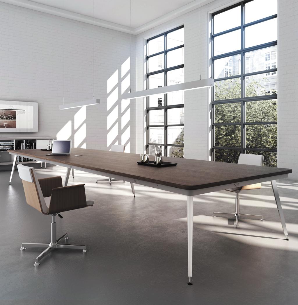
1 ELEVEN COLLABORATIVE
2 Table of Contents SUPPORT BRACE ASSEMBLY TABLE BASE FRAME ASSEMBLY LEG ATTACHMENT TOP JOINING PLATE ASSEMBLY... 6 TOP CLAMP/TOP SPACER INSTALLATION TOP PLACEMENT AND CONNECTION TOP ATTACHMENT.... 9
3 Support Brace Assembly THIS STEP IS NOT USED ON ALL TABLES is to be flipped over after legs are installed. NOTE: Frame is assembled upside-down. Frame NOTE: is to be flipped This over step after is legs used are only installed. on trapezoid tables and some boat-shaped tables. NOTE: This step is used only on trapezoid tables and some boatshaped tables. Position Support Brace so counter-sunk holes in Outside Leg Insert rail are aligned with holes on end of Support Brace. Insert Flat Head Cap Screws and tighten with 5MM allen wrench. Position Support Brace so counter-sunk holes in Outside Leg Insert rail are aligned with holes on end of Support Brace. Outside Leg Rail Insert Flat Head Cap Screws and tighten with 5MM allen wrench. Support Brace Flat Head Cap Screw 3 Completed Assembly
4 Table Base Frame Assembly THIS STEP IS NOT USED ON ALL TABLES NOTE: Frame is assembled upside-down. Frame is to be flipped over after legs are installed. TABLE BASE FRAME ASSEMBLY (This step is not used on all tables) NOTE: Frame is assembled upside-down. Frame is to be flipped over after legs are installed. Support Rail Clamp Position Double Top Support Rail Position and Single Double Top Top Support Rail and Single Top so counter-sunk holes in Inside Support Leg Insert Rail Rail so counter-sunk are aligned holes with in Inside Leg Insert Rail are aligned with holes on end of Support holes on end of Support Rails. Rails. Insert Flat Head Cap Screws and Insert tighten Flat Head with 5MM Cap Screws allen and tighten with 5MM allen wrench. wrench. Inside Leg Insert Rail, OR Straight Leg Insert Rail Single Top Support Rail Double Top Support Rail Position Support Rail Clamp where indicated & -TIGHTEN SECURELY- Loosen bolts in Support Rail Clamp with 5MM Allen wrench, and postion on Support Rails where indicated Loosen bolts in Support Rail Clamp on the with Assembly 5MM allen Master wrench, Illustration. and position on Support Rails where indicated on the Clamp onto Rails and - SECURELY TIGHTEN - bolts. Assembly Master Illustration. Install required rail on opposite end of rails. Clamp onto Rails and -SECURELY TIGHTEN- bolts. Install required rail on opposite end of rails. Flat Head Cap Screw 4
5 Leg Attachment wn. Frame led. Loosen bolts first! NOTE: Frame is assembled upside-down. Frame is to be flipped over after legs are installed. USE THIS METHOD FOR: Rectangular Tables 84 and Smaller Trapezoid Tables Square Tables Round Tables Three-legged Tables Use 5MM allen wrench to loosen leg bolts. DO NOT REMOVE BOLTS Slide leg between rails until leg bottoms out, leaving no gap. Tighten bolts. Outside Leg Rails USE THIS METHOD FOR: Rectangular Tables larger than 84 Loosen bolts first! Use 5MM allen wrench to loosen leg bolts. DO NOT REMOVE BOLTS Slide leg between rails until leg bottoms out, leaving no gap. Tighten bolts. On larger tables with 6 legs, center legs are inserted into Straight Leg Rails. Inside Leg Rail 5 Outside Leg Rail
6 NOTE: Flip assembled frame over to rest on feet at this time.. Top Joining Plate Assembly NOTE: All Top Joining Plates are pre-assembled THIS STEP with IS NOT clamps USED bolted ON ALL in TABLES place. NOTE: Flip assembled frame over to rest on feet at this time. Clip Top Joining Plates to inside faces of Double and Single Support Rails. NOTE: All Top Joining Plates are pre-assembled with clamps bolted in place. Position Plates so they are at the mid-point of the rails. Tighten Clamps with 5MM allen wrench. 120x42 & 120x48 RECTANGULAR TABLES 66 & 72 SQUARE TABLES AND TRAPEZOID TABLES 120 x 42 & 120 x 48 Rectangular Tables, 66 & 72 Square Tables and Trapezoid Tables Clip Top Joining Plates to inside faces of Double and Single Support Rails. Position Plates so they are at the mid-point of the rails. Clip Top Joining Plates to inside faces of Double and Single Support Rails. Tighten Clamps with 5MM allen wrench. Position Plate so it is at the mid-point of the rails. 96x48, 108x48 & 120x48 BOAT-SHAPED TABLES Tighten Clamps with 5MM allen wrench. Clip Top Joining Plates to inside faces of Double and Single Support Rails. Position Plates so it is at the mid-point of the rails. Tighten Clamps with 5MM allen wrench. 96 x 48, 108 x 48 & 120 x 48 Boat-Shaped Tables Clip Top Joining Plates to inside faces of Straight Leg Insert Rails (between the rails). ALL OTHER TABLES WITH 2 PIECE TOPS Slide Plates outward as far as they will go. Clip Top Joining Plates to inside faces of Straight Leg Insert Rails (between the rails). Tighten Clamps with 5MM allen wrench. Slide Plates outward as far as they will go. Tighten Clamps with 5MM allen wrench. All Other Tables with 2 Piece Tops 6
7 Top Clamp/Top Spacer Installation Snap Top Clamps onto rails where shown on Assembly Master Illustration. Flat surface of Top Clamp faces up. When correctly positioned, tighten Top Clamps (without over-tightening) using 5MM allen wrench. Snap Top Clamps onto rails where shown on Assembly Master Illustration. Flat surface of Top Clamp faces up. When correctly postioned, tighten Top Clamps (without over-tightening) using 5MM allen wrench. TOP Top Clamp Top Spacer Peel off adhesive backers on Top Spacers and adhere one on each leg. Peel off adhesive backers on Top Spacers and adhere one on each leg. 7
8 Top Placement and Connection Place top on frame. Two piece tops need to be placed so there is access to routes for Joint Fasteners on bottom side of top. Connect two halves of top together using Joint Fasteners in routed-out sections on connecting edges. Tighten with 7/16 wrench. 8
9 Top Attachment DISTANCE A DISTANCE B DISTANCE B DISTANCE A Position top so it is centered on the base. Use two #8 x 1 truss head screws per Top Clamp to secure top to base. If needed, use the same screws to fasten Top Joining Plate to top
MAG-CONV Basic, 48, 48R & Midline Front Mount
 Parts Required: Tools Used: Mag Wheels Brakes Brake Rods Mounting Bracket Anti Tippers 7/16" Wrench Screw Driver Rubber Mallet 5/8 Wrench 5mm Allen Wrench Step Execution Figures 1 Remove front 5" total
mila-wall (Series100) General Operating Instructions page 1 of 15
 General Operating Instructions page 1 of 15") mila-wall (Series100) General Operating Instructions page 1 of 15 Step #1: Before setting up walls, lower adjustable leveling feet on each panel approximately 1". This will allow access to the threaded
mila-wall (Series100) General Operating Instructions page 1 of 15 Step #1: Before setting up walls, lower adjustable leveling feet on each panel approximately 1". This will allow access to the threaded
Kai Installation Instructions
 Kai Installation Instructions Before Beginning Installation Read through the entire instruction thoroughly A minimum of 2 people are required for this assembly These instructions reflect typical assemblies;
IMPULSE G2/PULSE STATIC BRIDGE & RETURN MODULE. Drill. Desk Connecting. Outside by fastening the supplied wood screws from the HK-67 kit through the
 PART # 1608990 STATIC BRIDGE & RETURN MODULE 1. This sheet covers the steps to install a static bridge or return module with the FX no hinged access panel back option to a height adjustable freestanding
Equilibrium. Conference Table. Installation Instruction. Revision B 11/07/16
 Equilibrium Conference Table Installation Instruction Revision B 11/07/16 Equilibrium End User Agreement Enwork Equilibrium table bases must be installed directly onto a four inch minimum thickness concrete
ASSEMBLY AND ADJUSTMENT
 EDGE MONITOR ARM EDGE Rev A 2/17 Model EDGE-SLV Model EDGE-BLK Model EDGE-WHT ASSEMBLY AND ADJUSTMENT EDGE MONITOR ARM PARTS AND TOOLS PLEASE REVIEW these instructions before beginning the assembly and
General Guidelines:
 ASSEMBLY INSTRUCTIONS Congratulations on your new Patriot Dock purchase. This manual contains instructions to assemble basic dock configurations for use at typical residential shoreline application. Please
STEP 1 STEP 2 LEVELER KIT OPTION MOBILE CASTER KIT OPTION
 B SERIES INDUSTRIAL BENCHES TOOLS REQUIRED FOR ASSEMBLY Socket set, Open end wrench set, Cordless drill with 3/8" socket bit (Magnetic recommended). BEFORE ASSEMBLY Read through the assembly instructions
EDGE2 DUAL MONITOR ARM
 EDGE2 DUAL MONITOR ARM EDGE2 Rev A 2/17 Model EDGE2-SLV Model EDGE2-BLK Model EDGE2-WHT ASSEMBLY AND ADJUSTMENT EDGE2 DUAL MONITOR ARM PARTS AND TOOLS PLEASE REVIEW these instructions before beginning
The Queen Quilter Professional Quilters Kit Frame
 The Queen Quilter Professional Quilters Kit Frame Assembly Instructions Table of Contents: Before you begin......................... Pg. 2 Wood parts............................. Pg. 3 Hardware..............................
O-Sullivan King 4 Poster Bed O-Sullivan Queen 4 Poster Bed Parts and Hardware List
 Parts and Hardware List A. Left Headboard Post 1 pc B. Right Headboard Post 1 pc C. Left Footboard Post 1 pc D. Right Footboard Post 1 pc E. Headboard Panel 1 pc F. Footboard Rail 1 pc. Spindles 4 pcs
CV1B Sliding Table Installation and Setup Guide
 CV1B Sliding Table Installation and Setup Guide Tech Mark, Inc 7901 Industry Drive North Little Rock, AR 72117 tel (501) 945-9393 fax (501) 945-0312 www.tech-mark.com email: info@tech-mark.com The CV1B
Assembly Instructions & General Overview
 Assembly Instructions & General Overview 1. General Overview & Assembly Order...Page 3 2. Assembling the Structural Components Page 4-11 3. Power, Data, Power Poles and Cable Floor Boxes.Page 12-17 4.
STAKS. Crossover Casegoods ASSEMBLY INSTRUCTIONS
 STAKS Crossover Casegoods ASSEMBLY INSTRUCTIONS Installation Sequence 1. Wall Panels a. Connector Kit Part Identification 3 b. T - 3 Panel Connection Preparation 4 c. X Panel Connection Preparation 5 d.
INSTALLATION INSTRUCTIONS
 INSTALLATION INSTRUCTIONS PARTS REQUIRED Single QuickStand Lite Parts A (1) Lower Arm A B C D B (1) Upper Arm C (1) Base D (1) Base Plate E (1) M8 Dynamic Arm Long F (1) Clamp Bracket G H (1) VESA Plate
IMPULSE G2/PULSE STATIC BRIDGE & RETURN MODULE. Drill. Desk Connecting. Outside by fastening the supplied wood screws from the HK-67 kit through the
 PART # 1608990 STATIC BRIDGE & RETURN MODULE 1. This sheet covers the steps to install a static bridge or return module with the FX no hinged access panel back option to a height adjustable freestanding
installation guide ICON classic benching
 installation guide ICON classic benching Index ICON Installation Guide Single Run Frame Assembly... Worksurfaces and Electrical... Attaching Worksurfaces to Frame...6 Installing optional accessories...7
Antenna Workspaces Installation Instructions
 Antenna Workspaces Page Title January 2013 2 Page Title Worksurface x1 Worksurface x1 Worksurface x1 Worksurface x1 Leg x2 Horizontal Rail x2 Worksurface x1 Worksurface (x1) Leg x2 Leg (x2) Horizontal
HARVIL 3-IN-1 FLIP TABLE ASSEMBLY INSTRUCTIONS
 HARVIL 3-IN-1 FLIP TABLE ASSEMBLY INSTRUCTIONS NGD1018/1022 THANK YOU! Thank you for your purchase of this Harvil product. We work around the clock and around the globe to ensure that Harvil products maintain
x2 1/4 (6mm) Floor Anchor
 Floor Anchor") INSTALLATION GUIDE Main Components x1 Rail x5 Wall Spacer x2 Anti-jump Block x2 Straight Strap x1 Right Stopper x1 Left Stopper x5 5/16 (8mm x 60mm) Carriage Bolt x5 5/16 (8mm x25mm) Anchor x5 5/16 (8mm
INSTALLATION GUIDE Main Components x1 Rail x5 Wall Spacer x2 Anti-jump Block x2 Straight Strap x1 Right Stopper x1 Left Stopper x5 5/16 (8mm x 60mm) Carriage Bolt x5 5/16 (8mm x25mm) Anchor x5 5/16 (8mm
Q-Zone Hoop-Frame. Assembly Instructions. Copyright July 11, 2018 Grace Company (Reproduction Prohibited) Version 1.8
 Version 1.8") Q-Zone Hoop-Frame Assembly Instructions Copyright July 11, 2018 Grace Company (Reproduction Prohibited) Version 1.8 Table of Contents Table of Contents... i Warranty... ii Parts List Box 1...iii Box 2...
Q-Zone Hoop-Frame Assembly Instructions Copyright July 11, 2018 Grace Company (Reproduction Prohibited) Version 1.8 Table of Contents Table of Contents... i Warranty... ii Parts List Box 1...iii Box 2...
Fortress Fe Posts must always be secured to the deck framing. Fortress Fe Posts should never be attached to only the deck boards.
 Installation Instructions for Fortress Horizontal Cable Panel System with UB-05 Brackets and Fe Posts It is the responsibility of the installer to meet all code and safety requirements, and to obtain all
Parts List. U-DS92ST Ashley Creative Center With Padded Stool Assembly Instructions. [15] - Plastic Thick Washer (2 - pieces) [22] - Wrench (1 piece)
![Parts List. U-DS92ST Ashley Creative Center With Padded Stool Assembly Instructions. [15] - Plastic Thick Washer (2 - pieces) [22] - Wrench (1 piece)](/thumbs/82/86598067.jpg "Parts List. U-DS92ST Ashley Creative Center With Padded Stool Assembly Instructions. [15] - Plastic Thick Washer (2 - pieces) [22] - Wrench (1 piece)") [1] - 23.5 x 35.5 Top [8] - Drawer Support Rods Parts List [15] - Plastic Thick Washer (2 - pieces) [22] - Wrench [2] - Upper Base left End (1 pieces) [9] - Media Supports (1 pieces) [16] - loor Guides
[1] - 23.5 x 35.5 Top [8] - Drawer Support Rods Parts List [15] - Plastic Thick Washer (2 - pieces) [22] - Wrench [2] - Upper Base left End (1 pieces) [9] - Media Supports (1 pieces) [16] - loor Guides
OXYGEN INSTALLATION. Revision date
 12345 1 Hardware List 12345 Flat head wood screw #9 x 7/8 long with #2 Phillips drive, silver Used to attach surfaces and end panels Hex set screw ½-13 x 2 long with 1/4 hex drive, black Used on Legs Hex
HQ Studio Frame Two-Foot Section Assembly Instructions From Twelve-Foot to Ten-Foot
 HQ Studio Frame Two-Foot Section Assembly Instructions From Twelve-Foot to Ten-Foot HQ Studio Frame Two-Foot Includes: Includes one (1) two-foot table frame with plastic top, two (2) two-foot track supports,
For additional assistance call
 The following pages will help guide you through the process of assembling your new 48 custom prize wheel. Choose an assembly area with plenty of room to lay your pieces on the floor and also a bench or
Heavy Duty Ceiling Tilt Mount Installation Manual
 HD-CTM-5580 Heavy Duty Ceiling Tilt Mount Installation Manual *This Installation requires a minimum of two people. For your safety: Read the complete instruction manual before starting an installation
On-Roof Mounting Sets for Flat-Plate Collectors
 Engineering Submittal Sheet Installation sets for collectors Fig. 1 Installation set for 2 collectors 1 basic installation set, 1 extension installation set Basic installation set for each collector array
GATE INSTALLATION INSTRUCTIONS
 GATE INSTALLATION INSTRUCTIONS 1) Ensure posts for gate are fully installed. Posts need to be securely fastened to decking or concrete such that they will not sag with weight of the gate. For a single
Ceiling Tile Installations Part 1. Sheetrock Installations Part 2. WolfVision Support 2055 Sugarloaf Circle, Suite 125 Duluth, GA 30097
 Ceiling Tile Installations Part 1 Sheetrock Installations Part 2 WolfVision Support 2055 Sugarloaf Circle, Suite 125 Duluth, GA 30097 (877) 873-WOLF support@wolfvision.us 0 EYE Series Mounting Kit Part
Continuum Frame Assembly Instructions
 Continuum Frame Assembly Instructions Copyright January 1, 2017 Jim M. Bagley, GraceWood, Inc (Reproduction Prohibited) Version 2.2 Table of Contents Continuum Frame Table of Contents... i Warranty...ii
Gambrel Barn Construction Manual 8x8 through 16x24 Units
 Gambrel Barn Construction Manual 8x8 through 16x24 Units Tools Needed: Cordless drill (12V or higher) #2 square drive bit Hammer 6 step ladder Tape measure Square utility knife w/ blade & hook blade Little
HQ Pole Upgrade Kit for HQ Adjustable Table and HQ QuilTable Assembly Instructions 1
 HQ Pole Upgrade Kit for HQ Adjustable Table and HQ QuilTable Assembly Instructions QF09775 The pole upgrade kit can be used with or without the QF09700 HQ Precison-Glide track upgrade kit. What s Included
B B B
 Winchester SXP Gauge Tactlite Six Position Adjustable Shotgun Stock with Scorpion Recoil System B..0.00 B..0.00 B..0.00 Removable/Adjustable Tactical Cheekrests X Scorpion Recoil Pad Dual Sided QD Attachment
This manual will aid in the assembly of the FireBall V90 and FireBall X90. The assembly of both machines will be identical, unless specified.
 This manual will aid in the assembly of the FireBall V90 and FireBall X90. The assembly of both machines will be identical, unless specified. Step #1 Lay all parts out to verify quantities. (2) 2 x 25-1/4
EPPA2-KIT DUAL MONITOR ARM CONVERSION
 EPPA2-KIT DUAL MONITOR ARM CONVERSION EPPA2-KIT Rev A 10/17 Model EPPA2-KIT-XXX ASSEMBLY AND ADJUSTMENT EPPA2-KIT PARTS AND TOOLS PLEASE REVIEW these instructions before beginning the assembly and adjustment
ASSEMBLY AND ADJUSTMENT
 EPPA MONITOR ARM EPPA Rev A 10/17 Model EPPA-XXX ASSEMBLY AND ADJUSTMENT EPPA MONITOR ARM PARTS AND TOOLS PLEASE REVIEW these instructions before beginning the assembly and adjustment procedures. Check
Transit Connect Full/Half Installation Instructions
 GATHER THESE TOOLS FOR ASSEMBLY & INSTALLATION 7/16 wrench, T45 Torx socket, 7/16 socket, 3/8 drive ratchet - 3/8 socket One 1/8 square end driver bit provided - Electric drill/driver/18v cordless One
CMT Enlock Jig Owner s Manual
 Thank you for purchasing the CMT Enlock Jig. This jig will simplify joinery in your shop, and on the job site. Please read the instructions thoroughly before using the Enlock Jig. Router requirements A
User Instructions Multiline Otter Scoreboard Caddy Assembly
 List of parts: User Instructions Multiline Otter Scoreboard Caddy Assembly Single Caddy Double Caddy 1 1 Base assembly with attached wheels 2 4 1 1 2 4 4 8 10 20 12 Uprights (60 or 74 aluminum extrusion)
TRAILMATE METEOR ASSEMBLY MANUAL
 TRAILMATE METEOR ASSEMBLY MANUAL The Trailmate Meteor recumbent has been designed for easy assembly. This means more time to enjoy the smooth ride with single speed, 3 speed coaster brake and 21 speed
Hover. Installation Instructions. Raised Panel. Version
 Installation Instructions Version 8-2-17 Raised Panel Table of Contents Page Raised Panel Trough 3-13 Platform Trough 14-20 Platform 120 Degree Trough 21-24 Electrical 25-28 Type A Electric Bases 29-31
55000/55010 Installation Instructions
 A. Install 55015 B. Bolt roof rails, 55020/55025, to front hoop. C. Assemble 55026 D. To install without drilling into bumper. E. If mounting directly to bumper. A. 55015 Installation Instructions 55000/55010
Step 1: The larger tower box contains the tower machine, a set of Silver 100 Lid Keys, and a set of Black 002 Coin Box Keys
 2 3 Step 1: Each tower is shipped as two boxes the large tower box and the smaller stand box. Open each of the boxes and inventory each of the parts before starting assembly to ensure all parts have arrived.
INSTALLATION INSTRUCTIONS VENETIAN 84" SLIDING SHOWER DOOR SYSTEM (180º INSTALLATION)
") INSTALLATION INSTRUCTIONS VENETIAN 84" SLIDING SHOWER DO SYSTEM (180º INSTALLATION) 28539 Industry Drive, Valencia, CA 91355 Toll Free Phone: (877) 728-3874 Toll Free Fax: (888) 440-9567 Phone: (661) 775-1675
INSTALLATION INSTRUCTIONS VENETIAN 84" SLIDING SHOWER DO SYSTEM (180º INSTALLATION) 28539 Industry Drive, Valencia, CA 91355 Toll Free Phone: (877) 728-3874 Toll Free Fax: (888) 440-9567 Phone: (661) 775-1675
#11179 Wellington ARBOR
 #11179 Wellington ARBOR Assembly INSTRUCTIONS TOOLS NEEDED Tape Measure Variable Speed Drill with #2 Phillips Bit (recommended) or Phillips Screwdriver Hammer or Mallet ARBOR SIDE PANEL ASSEMBLY (Refer
mounting instruction plateau #177 #177 Plateau - mounting out-sider a/s Kigkurren 8A, Islands Brygge DK-2300 Copenhagen S
 mounting plateau instruction #177 Index: page Parts included for mounting: Unpacking the shipment...03 Preparations for mounting the legs...04 Legs mounting, step 1...05 Legs mounting, step 2...06 Legs
CNC Router Parts PRO Machine Kit Cable Track Installation Instructions
 1 1 X CABLE TRACK TRAYS & BRACKETS The cable track on the side of the system is supported by a metal tray (or multiple trays for longer systems such as a PRO4896). These trays hang from brackets on the
Baby Grande with Crank, Housing, and Side Rails Installation Instructions
 Baby Grande with Crank, Housing, and Side Rails Installation Instructions Tools Needed Hardware Provided (per shade) Hardware Needed Drill 3/8 Metal Drill Bit ¼ Masonry Drill Bit Measuring Tape Pencil
STAKS BENCHING ASSEMBLY INSTRUCTIONS
 STAKS BENCHING ASSEMBLY INSTRUCTIONS TABLE OF CONTENTS BASE ASSEMBLY 3 ORGANIZER INSTALLATION 4-5 PRIVACY SCREEN INSTALLATION 6 WORKSURFACE INSTALLATION 7 TOP STRAP INSTALLATION 8-9 POWER INSTALLATION
How to build a hockey stick bench
 How to build a hockey stick bench The hockey stick bench is a great piece of fully functional furniture that doesn t require a lot of sticks. Composite sticks are really strong, so even if you space them
Pickup Box Utility Rack Package Installation (Instruction ID: )
") 017 Chevrolet Colorado Pickup - WD (VIN S) Canyon, Colorado Accessory Installation Manual N America Document ID: 3966961 Pickup Box Utility Rack Package Installation (Instruction ID:3144879) Installation
017 Chevrolet Colorado Pickup - WD (VIN S) Canyon, Colorado Accessory Installation Manual N America Document ID: 3966961 Pickup Box Utility Rack Package Installation (Instruction ID:3144879) Installation
Yardistry. External Display YP *Time required for assembly approximately 1.5-2hrs
 Yardistry External Display YP40030 *Time required for assembly approximately 1.5-2hrs Components 4 Packages of Panel Clips (Includes 6 Panel Clips and Hardware) 3 16 1/2 x 16 1/2 Signs (hardware Included)
BARN DOOR HARDWARE KIT
 INSTALLATION GUIDE Main Components x1 Rail x5 Wall Spacer x2 Anti-jump Block x2 Bent Strap x1 Right Stopper x1 Left Stopper x5 5/16 (8mm x 60mm) Carriage Bolt x5 5/16 (8mm x25mm) Anchor x5 5/16 (8mm x
IN 578. Tools Required. Torque Specification: 10mm Socket 7/16 Socket 1/2 Socket 1/2 Wrench 7/16 Wrench 1/8 Allen Wrench.
 Tools Required 2011-C Ford F250/F350 No Drilling into Vehicle is Required 10mm Socket 7/16 Socket 1/2 Socket 1/2 Wrench 7/16 Wrench 1/8 Allen Wrench FL277 x 1 Torque Specification: 1/4 Bolts - 6 Ft Lbs.
PLEASE CHECK ALL BOXES FOR HARDWARE BEFORE DISCARDING WARRANTY AND USER INFORMATION CAN BE FOUND AT THE END OF THESE INSTRUCTIONS
 Thank you for purchasing the SleepSafe Safety Bed. With proper care, your bed will provide years of safe use. Carefully unpack all the contents of your bed and verify that all parts are included using
The Phoenix. Professional Quilting Frame. Copyright January 1, 2016 Jim M. Bagley, GraceWood, Inc (Reproduction Prohibited) Version 2.
 Version 2.") The Phoenix Professional Quilting Frame Copyright January 1, 2016 Jim M. Bagley, GraceWood, Inc (Reproduction Prohibited) Version 2.1 1 The Phoenix Professional Quilting Frame Parts List Box 1...3 Box
The Phoenix Professional Quilting Frame Copyright January 1, 2016 Jim M. Bagley, GraceWood, Inc (Reproduction Prohibited) Version 2.1 1 The Phoenix Professional Quilting Frame Parts List Box 1...3 Box
PFD-22 Top OHC Patch Fitting & PFD-10 Bottom Patch Fitting Installation Instructions
 Top OHC Patch Fitting & Bottom Patch Fitting Installation Instructions For Installation Assistance, Call 855.594.6989 www.assaabloyglass.us Tools Needed: Torque Wrench and Bit 5mm Allen Wrench 6 7 /16"
Leafy Greens Spinner Construction Manual
 Leafy Greens Spinner Construction Manual University of Houston Conrad N. Hilton College Food Science Lab Materials list: Base and Armature Approximately 8-1 PVC cut into sections o 3-22.5 o 2-7 o 2-4 o
Thank you for purchasing our product! *Please read these instructions and follow them step by step.*
 07/07/08.rev1 PAGE 1 OF 11 601AL VERTICAL 60120VL LIFT W/CHAIN DRIVE WINCH Thank you for purchasing our product! *Please read these instructions and follow them step by step.* Step 1. Separate and group
Fortress Fe Posts must always be secured to the deck framing. Fortress Fe Posts should never be attached to only the deck boards.
 Installation Instructions for FortressCable H-Series Cable Panel System With UB-05 Brackets and Fe Posts It is the responsibility of the installer to meet all code and safety requirements, and to obtain
WG-4 Wall Guard Installation Instructions
 WG-4 Wall Guard Installation Instructions Architectural Products Division Step 1: Determine top of wall guard and snap a chalk line 1/8 below to locate top of aluminum retainer, see fig 1. Store material
2010 KIDS CENTER #6 K-06
 K-06 INSTALLATION GUIDELINES USER GROUP: 2-5 RECOMMENDED CREW: 2 people TOOLS REQUIRED: Tape measure Level High- speed 3/8 electric drill w/clutch NOTE: Use of any other driver may result in damage to
86-1/2" TRACK INSTALLATION GUIDE
 BARN TRACK 86-1/2" TRACK INSTALLATION GUIDE READ ALL INSTRUCTIONS AND REVIEW DIAGRAMS BEFORE BEGINNING THE INSTALLATION TO GET A THOROUGH UNDERSTANDING OF THE PROCESS. BEFORE YOU BEGIN This kit comes with
TREX ENHANCE RAILING (Also Applies to Trex Select Railing) Installation Instructions
 Installation Instructions") TREX ENHANCE RAILING (Also Applies to Trex Select Railing) NOTE: All Enhance Railing lengths are manufactured at CLEAR SPAN dimensions (spanning between space of posts): 7" for 6' clear span. Note that
TREX ENHANCE RAILING (Also Applies to Trex Select Railing) NOTE: All Enhance Railing lengths are manufactured at CLEAR SPAN dimensions (spanning between space of posts): 7" for 6' clear span. Note that
DeckRail A Product of DeckRite LLC 3912 East Progress North Little Rock, AR Phone: (501) Fax: (501)
 Fax: (501)") Disclaimer: Deck Rail Glass Railing Installation Guide This guide is not intended to replace a trained professional installer. The drawings and instructions contained within are for demonstration purposes
Disclaimer: Deck Rail Glass Railing Installation Guide This guide is not intended to replace a trained professional installer. The drawings and instructions contained within are for demonstration purposes
POWER PET. Low-E Automatic Patio Pet Door Installation and Operating Instructions
 POWER PET Low-E Automatic Patio Pet Door Installation and Operating Instructions Power Pet, Regular Height, Patio Door Assembly Steps Estimated assembly time: Under 1 hour STEP 1: Assemble the tools you
Riverside. Oakmont Queen Storage Bed Assembly Instructions
 Queen Storage Bed Page 1 of 7 8 pcs. 8 pcs. 1 pc. 1 pc. 8 pcs. 8 pcs. 8 pcs. 8 pcs. 1 pc. 1 pc. 20270 --5/0 Sleigh Headboard 20274 --5/0-6/6 Bed Rails 20273 -- 5/0 Storage Footboard, Panels, Slats Queen
x2 1/4 (6mm) Floor Anchor
 Floor Anchor") Main Components x1 Rail x5 Wall Spacer x2 Anti-jump Block x2 Bent Strap x1 Right Stopper x1 Left Stopper x5 5/16 (8mm x 60mm) Carriage Bolt x5 5/16 (8mm x25mm) Anchor x5 5/16 (8mm x 90mm) Wall Screw x2
Main Components x1 Rail x5 Wall Spacer x2 Anti-jump Block x2 Bent Strap x1 Right Stopper x1 Left Stopper x5 5/16 (8mm x 60mm) Carriage Bolt x5 5/16 (8mm x25mm) Anchor x5 5/16 (8mm x 90mm) Wall Screw x2
Assembly Instructions
 InTandem Table System November 20 InTandem Table System - Worksurface #4 x/" 4 wood screw power beam Tools Provided T-0 Extended Torx Driver T-25 Torx Driver Additional Tools Required Soft protective
HOUSE PARTS PACKED IN HOUSE BOX PARTS IN PLASTIC BAG (HARDWARE) PARTS IN SMALL PLASTIC BAG (FLOOR CLIPS) PARTS PACKED IN BUNDLE
 PARTS IN SMALL PLASTIC BAG (FLOOR CLIPS) PARTS PACKED IN BUNDLE") Check parts against this list before starting assembly. Refer to illustrations on pages 6 and 7 to view house parts. If any shortages are found, refer to Packing Slip for claim instructions. Item 3 5 6
Check parts against this list before starting assembly. Refer to illustrations on pages 6 and 7 to view house parts. If any shortages are found, refer to Packing Slip for claim instructions. Item 3 5 6
Series 4 HV Single Monitor Lift Assembly Instructions
 6703 Zinser Street Schofield, WI 54476 6/13/17 Series 4 HV Single Monitor Lift Assembly Instructions Read all the instructions before beginning. Hardware Pack # 53368 Page1 OF 6 Tools Required for Assembly:
EmagiKit. Privacy Pod Plus. Quiet. Easy. Affordable. INSTRUCTIONS ASSEMBLY
 EmagiKit Privacy Pod Plus Quiet. Easy. Affordable. INSTRUCTIONS ASSEMBLY DIMENSIONS AND COMPONENTS 47 47 Ceiling Unit 2-B 2-L 2-R Glass Door Corner Trim Door Handle 90 Adjustable Height Work Surface 1-B
BSM, GSM & GSS. Joint Kit Instruction. (Modified for IMPACT) (NSF Certified) Curved Glass Fresh Meat Delicatessen and Seafood Merchandisers
 (NSF Certified) Curved Glass Fresh Meat Delicatessen and Seafood Merchandisers") BSM, GSM & GSS Joint Kit Instruction (Modified for IMPACT) (NSF Certified) Curved Glass Fresh Meat Delicatessen and Seafood Merchandisers February, 1999 JOINT ASSEMBLY PARTS LIST Item Quantity Description
BSM, GSM & GSS Joint Kit Instruction (Modified for IMPACT) (NSF Certified) Curved Glass Fresh Meat Delicatessen and Seafood Merchandisers February, 1999 JOINT ASSEMBLY PARTS LIST Item Quantity Description
Topo Freestanding Applications - Private Office
 4 3 2 Topo Freestanding Applications - Private Office Combo Wrench If you have a problem, question, or request, call your local dealer, or Coalesse at 1.800.627.6770 Or visit our website: www.coalesse.com
Replacing the Reciprocator on an SWF Multi-head.
 Replacing the Reciprocator on an SWF Multi-head. Follow the instructions below to replace the reciprocator in the SWF multi-head machines. The tools required are found in the tool kit that came with the
Odyssey Elementary Stem Installation
 Tools Needed Grease Allen Wrenches Open/Closed end wrench Adjustable wrench Note: Tools needed will vary depending on the style of headset compression cap and bolt being used. Removing the Handlebars Loosen
Replacing the Reciprocator on the SWF Compact Series Machine (601C and 1201C)
") Follow the instructions below to replace the reciprocator in the SWF Compact series machines. The tools required can be found in the tool kit that came with the machine. Preparation 1. First, place the
Follow the instructions below to replace the reciprocator in the SWF Compact series machines. The tools required can be found in the tool kit that came with the machine. Preparation 1. First, place the
CONTENTS TOOL LIST U P S I D E I N N O V A T I O N S, L L C RAMP AND STEP SYSTEM ASSEMBLY INSTRUCTIONS. Revised: June 2013
 U P S I D E I N N O V A T I O N S, L L C RAMP AND STEP SYSTEM ASSEMBLY INSTRUCTIONS TOOL LIST Required Tools: - Reciprocating Saw with Metal Cutting Blade - Drill - 7/16 Drill Bit for Metal Drilling -
IMPORTANT: PLEASE RETAIN THIS INSTRUCTION MANUAL FOR FUTURE REFERENCE
 IMPORTANT: PLEASE RETAIN THIS INSTRUCTION MANUAL FOR FUTURE REFERENCE 005-07 Cadillac STS Classic 3D Z, Classic Dual Weave, Classic Mesh & Classic Black Mesh Grilles B 7 HR 3 STS Classic 3D Z Grille Part
Jenny Legs Assembly Instructions
 Jenny Legs Assembly Instructions R EXTENDED PHILLIPS BIT MM ALLEN WRENCH 6MM HEX DRIVE /" 007 Steelcase Inc. Grand Rapids, MI 90 U.S.A. Printed in U.S.A. Page of 6 88000 Rev F Jenny Club Instructions:
Stag Hanger ASSEMBLY INSTRUCTIONS
 Stag Hanger ASSEMBLY INSTRUCTIONS STAG HANGER Recommended Tools Drill with 1/8, 1/4, and 3/8 Drill Bits, 1-1/8 Forstner Bit or 1-1/8 Spade Bit, and Phillips Bit 9/16 and 5/8 Combination Wrench Socket Wrench
JEEP JK ( 5 DOOR ) SLIMLINE II - FULL TRAY EXTREME RACK KIT
 SLIMLINE II - FULL TRAY EXTREME RACK KIT") JEEP JK ( 5 DOOR ) SLIMLINE II - FULL TRAY EXTREME RACK KIT FAJK001 / KRJW014T INSTALL TIME: 2.5 Hours NOTE: Your Jeep JK (5 Door) Extreme Roof Rack Kit consists of four boxes. (1) the Tray, (2) the Roll
JEEP JK ( 5 DOOR ) SLIMLINE II - FULL TRAY EXTREME RACK KIT FAJK001 / KRJW014T INSTALL TIME: 2.5 Hours NOTE: Your Jeep JK (5 Door) Extreme Roof Rack Kit consists of four boxes. (1) the Tray, (2) the Roll
π H-4408 ALUMINUM BLEACHERS 5-ROW x 15' PARTS uline.com TOOLS NEEDED
 π H-4408 1-800-295-5510 uline.com ALUMINUM BLEACHERS 5-ROW x 15' TOOLS NEEDED Square Tape Measure Rivet Gun 3/16" Drill Bit 1/2" Wrench Socket Wrench 1/2" Deep Well Socket #2 Phillips Bit Rubber Mallet
Installation Instructions - Model V4JSD 1
 Installation Instructions - Model V4JSD 1 Support Assemblies: Parts list: (Note see enclosed cut sheet for quantities and dimensional information) A vertical structural member (1 ½ x 1 ½ modular frame)
MPA-9000 Universal Ceiling Projector Mount Kit
 I N S T R U C T I O N M A N U A L Universal Ceiling Projector Mount Kit The Universal Ceiling Projector Mount provides a unique, simplified method of ceiling mounting your inverted projector. This low
for HQ 18 Avanté HQ Studio Frame
 HQ Studio Frame for HQ 18 Avanté Assembly Instructions Table of Contents Parts List page 2 Hardware List page 3 HQ Studio Frame Box Contents page 4 Step 1- Frame Side Assembly page 5 Step 2- Table Assembly
MultiTable Mod-E 2 Electric Standing Desk
 The Height of Healthy Design MultiTable Mod-E 2 Electric Standing Desk ASSEMBLY INSTRUCTIONS MultiTable Mod-E 2 Electric Standing Desk Frame PARTS AND TOOLS PLEASE REVIEW these instructions before beginning
INSTALLATION OF THE TRACK FOR THE STRAIGHT SIDE STEEL LADDER
 ASSEMBLY OF THE 7180 STRAIGHT SIDE STEEL LADDER TOOLS REQUIRED FOR ASSEMBLY SAFETY GLASSES (2) 1 / 2 WRENCHES OR SOCKETS STEP LADDER OF APPROPRIATE HEIGHT (2) 7 / 16" WRENCHES OR SOCKETS HACKSAW FLAT HEAD
Nest Storage Bed in Fabric Designed by Niels Bendtsen
 General Assembly Instructions Assembly requires two people and 1 2 hours. Assemble bed as near as possible to final resting area. Identify all parts and hardware before beginning assembly. Retain packaging
HQ Studio2 Frame. Assembly Instructions. Table of Contents. What s Included
 HQ Studio2 Frame Assembly Instructions UPDATED NOVEMBER 2017 Table of Contents Parts List... page 2 Hardware List.... page 3 HQ Studio Frame Box Contents...page 4 Step 1- Frame Side Assembly... page 5
Assembly Instructions. Table of Contents
 HQ Little Foot Assembly Instructions Back of Handi Quilter, Inc. 501 North 400 West North Salt Lake, UT 84054 1-877-697-8458 Front of 2015 Handi Quilter, Inc. www.handiquilter.com Printed in the United
HQ Studio2 Frame. Assembly Instructions. Table of Contents. What s Included
 HQ Studio2 Frame Assembly Instructions UPDATED June 2018 Table of Contents Parts List... page 2 Hardware List.... page 3 HQ Studio Frame Box Contents...page 4 Step 1: Frame Side Assembly... page 5 Step
Required Tools: Suggested Additional Tools: 1 Cordless Drill with Robertson Bits 1 Ratchet Wrench 1 7/16 or 11mm socket 1 7/16 or 11mm Gear Wrench
 Thank you for your recent purchase of a Cabinets by Hayley garage cabinet system. You are about to experience the best made cabinets that you can purchase. Cabinets by Hayley are designed for beauty and
Post & Rail Crossbuck
 Post & Rail Crossbuck 1. Getting Started 6. Crossbuck Be sure to call underground prior to digging Assemble gates (if necessary) and decide where they will be located Stake out the fence line Space and
Rockwell 4-in-1 Sliding Door
 Rockwell 4-in-1 Sliding Door ASSEMBLY INSTRUCTIONS ROCKWELL 4-IN-1 SLIDING DOOR Recommended Tools Drill with Phillips Bit Socket Wrench with 7/16 Socket Rubber Mallet Adjustable Square ROCKWELL 4-IN-1
CTTR Tire Rack Required tools
 CTTR Tire Rack Required tools Torque wrench, ratchet, 9/16 socket, tape measure, and square edge. ASSEMBLY REQUIREMENTS *Torque all T-bolt nuts to 35-40 foot pounds. Failure to follow the assembly instructions
Motorized or Crank Operated Fortress Zipper Track Shade with Housing and Side Track Installation Instructions
 Motorized or Crank Operated Fortress Zipper Track Shade with Housing and Side Track Installation Instructions Tools Needed Drill 3/8 Metal Drill Bit ¼ Masonry Drill Bit Measuring Tape Pencil 4 Level Phillips
IDR assembly instructions:
 IDR assembly instructions: Required Tools: 2 X 12mm Open End Wrench 14mm open end wrench #2 Phillips Head Screw Driver (Drill with adjustable torque clutch recommended) 8mm nut driver (Supplied in IDR-AK)
Queen Wingback Bed King Wingback Bed
 Parts and Hardware List A. Side Rails with Attachment Hooks 2 pcs B. Foot Rail 1 pc C. Head Rail 1 pc D. Center Support Slat 1 pc E. Leg Supports 3 pcs F. Support Slats 4 pcs G. Flat Washers 8 pcs H. Lock