Motor-CAD winding temperature model verification using Finite Element Analysis
|
|
|
- Bruce Davis
- 5 years ago
- Views:
Transcription

1 Motor-CAD winding temperature model verification using Finite Element Analysis Description Motor-CAD uses a layered model, where the copper, insulation and impregnation are evenly distributed through the slot, to produce the equivalent thermal circuit for the winding. This document gives a brief description of how to check the Motor-CAD winding model using the Flux2D finite element analysis tool. Machine Geometry The standard default machine geometry for a BPM machine is used in this tutorial as shown below. Page 1
2 Winding Model The winding editor view shows the winding layer model used for this machine. The winding layer model shows how the copper, insulation and impregnation is evenly distributed throughout the slot. In this case we will model 50 conductors of 0.8mm diameter wire in the slot. There is also a coil divider of width 1mm down the centre of the slot as set up and shown below. Page 2
3 Page 3

4 The conductors can be viewed in the slot by selecting the Show Conductors option shown below: In the winding editor view the conductors are now shown in the slot: Page 4
5 Losses 250W will be specified as the stator copper losses as shown below. All the other loss values will be taken as the default values for this example. Page 5

6 Other model settings For the rest of the model the default cooling options, materials, interface gaps etc will be used for this example. Page 6

7 Steady State Thermal Results The average (152 degc) and maximum (156 degc) active section winding temperatures are shown in the schematic view below. Page 7

8 Verification of Motor-CAD Winding Layer Model using a Finite Element model The Flux2D Finite Element tool will be used to verify the Motor-CAD winding model. As Motor-CAD has a complex 3D model and Flux2D is in 2D then the Motor-CAD model needs to be modified to give an equivalent 2D model. Note: This modified Motor-CAD model is only to be used for the winding calibration using Flux2D. Creating Motor-CAD 2D model This Motor-CAD 2D model is created as follows. Set the pole number equal to the number of slots to allow symmetry to be used and reduce the size of the model. Page 8

9 Set the stator lamination to housing interface gap to 0mm as this is not modeled in the FE model. Page 9
10 Set the EWdgMLT (end winding mean length per turn) to 0 to ensure all losses are in the active section of the machine. Set the Copper diameter to 0.8mm so that there is no insulation on the wire. This helps keep the size of the mesh down. With a small number of conductors it should be possible to include the wire insulation in the FE model. Note: the line region functionality does currently not work in Flux2D for thermal problems. This means that if you have many conductors with a small insulation layer it may produce an overly large mesh that cannot be solved. To get round this it may be necessary to remove the insulation from the Motor-CAD model as shown above. (i.e. set Wire Diameter = Copper Diameter) Page 10
11 You can also adjust the spacing of the conductors in the winding view as shown below. Always check that the required number of conductors have been drawn in the slot by checking the conductors/slot drawn value is equal to the conductors/slot value. Page 11

12 The circuit should be modified to remove the active to end winding resistances and the stator to rotor resistance path as shown below. The modified circuit with the isolated winding node can be seen in the circuit view as shown below. Page 12
13 The steady state Motor-CAD 2D winding model results are shown below. Page 13


14 Creating Flux2D model You can then export the Motor-CAD 2D winding model to Flux to view the temperatures inside the slot. To do this you select the File Menu->Tools>Flux2D as shown below. This will create several script files myname.py, myname_1.py, myname_2.py. If you run the myname.py file from the Flux supervisor this runs all the other files and it will produce the model and also solve it in Flux2D version 10.3 and later. Select the file to create and then click the Export button as shown below. If you are using a version of Flux 10.3 or later then select yes and the script will be generated that will also solve the model. Page 14
 The script")

15 The script should then be run from the Flux supervisor as shown below. (It is also possible to run the script from inside PreFlux2D) The script will take approximately 5 minutes to run depending on the number of conductors and the speed of your machine. The results are displayed as shown below. Page 15
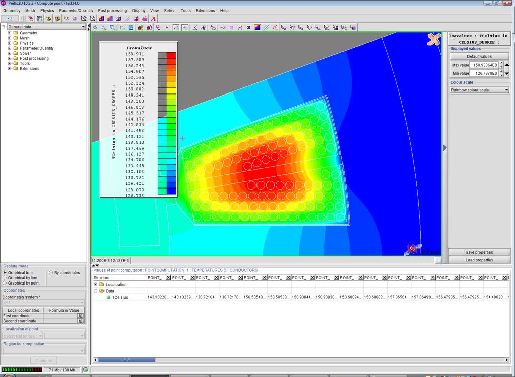
16 Page 16


17 The temperatures of each of the conductors can be exported to Excel to allow calculation of the average and hotspot winding temperatures. From Flux2D model: Hotspot winding temperature = 159 degc Average winding temperature = 148 degc Page 17

18 Calibrating the Motor-CAD model The Motor-CAD model can be calibrated by changing the value of the impregnation goodness in the active section. This varies the thermal resistance values in the layered model. The calibrated temperatures are shown below. Page 18
 Winding hotspot temperature (DegC) 148 155 151 159 166 159 It can be seen that Motor-CAD is slightly over")
19 Conclusions The different winding temperatures predicted are shown in the table below. Flux model Motor-CAD model Calibrated Motor-CAD model Average winding temperature (DegC) Winding hotspot temperature (DegC) It can be seen that Motor-CAD is slightly over predicting the winding temperature for this machine. This gives confidence that the Motor-CAD layered winding model will not under predict the temperature under different operating conditions. The Motor-CAD model can be calibrated to give an accurate average or hotspot temperature. In this example the calibrated model gives a slight over prediction in average winding temperature but gives good agreement with the winding hotspot temperature. Page 19
Electromagnetic and thermal model for Brushless PM motors
 22 December 2017 Motor-CAD Software Tutorial: Electromagnetic and thermal model for Brushless PM motors Contents 1. Description... 1 2. Model Definition... 2 3. Machine Geometry... 3 4. Winding Definition...
Motor-CAD Brushless PM motor Combined electromagnetic and thermal model (February 2015)
") Motor-CAD Brushless PM motor Combined electromagnetic and thermal model (February 2015) Description The Motor-CAD allows the machine performance, losses and temperatures to be calculated for a BPM machine.
Motor-CAD Brushless PM motor Combined electromagnetic and thermal model (February 2015) Description The Motor-CAD allows the machine performance, losses and temperatures to be calculated for a BPM machine.
Motor-CAD reduced node model tutorial (February 2015)
") Motor-CAD reduced node model tutorial (February 2015) Description Motor-CAD allows the machine performance, losses and temperatures to be calculated for a BPM machine. In this tutorial we will describe
Motor-CAD reduced node model tutorial (February 2015) Description Motor-CAD allows the machine performance, losses and temperatures to be calculated for a BPM machine. In this tutorial we will describe
Contents. About the Authors. Abbreviations and Symbols
 About the Authors Preface Abbreviations and Symbols xi xiii xv 1 Principal Laws and Methods in Electrical Machine Design 1 1.1 Electromagnetic Principles 1 1.2 Numerical Solution 9 1.3 The Most Common
Linked Electromagnetic and Thermal Modelling of a Permanent Magnet Motor
 Linked Electromagnetic and Thermal Modelling of a Permanent Magnet Motor D. G. Dorrell*, D. A. Staton, J. Hahout*, D. Hawkins and M. I. McGilp* *Univerity of Glasgow, Glasgow, UK Motor Design Ltd, Tetchill,
Combined analytical and FEM method for prediction of synchronous generator no-load voltage waveform
 Combined analytical and FEM method for prediction of synchronous generator no-load voltage waveform 1. INTRODUCTION It is very important for the designer of salient pole synchronous generators to be able
The effect analysis of single-double layers concentrated winding on squirrel cage induction motor
 International Conference on Advanced Electronic Science and Technology (AEST 2016) The effect analysis of single-double layers concentrated winding on squirrel cage induction motor a Jianjun Fang, Yufa
TUTORIAL Inductor Loss Calculation in Thermal Module
 TUTORIAL Inductor Loss Calculation in Thermal Module October 2016 1 The Thermal Module provides the capability to calculate the winding losses, core losses, and temperature rise of inductors based on standard
Three-Phase Induction Motors. By Sintayehu Challa ECEg332:-Electrical Machine I
 Three-Phase Induction Motors 1 2 3 Classification of AC Machines 1. According to the type of current Single Phase and Three phase 2. According to Speed Constant Speed, Variable Speed and Adjustable Speed
DOCUMENTATION OF INSULATION MEASUREMENTS FOR ELECTRICAL MACHINES
 FRAUNHOFER INSTITUTE FOR MANUFACTURING TECHNOLOGY AND ADVANCED MATERIALS IFAM DOCUMENTATION OF INSULATION MEASUREMENTS FOR ELECTRICAL MACHINES Processing period: February 2018 September 2018 Michael Gröninger
Effects of the Short-Circuit Faults in the Stator Winding of Induction Motors and Fault Detection through the Magnetic Field Harmonics
 The 8 th International Symposium on ADVANCED TOPICS IN ELECTRICAL ENGINEERING The Faculty of Electrical Engineering, U.P.B., Bucharest, May 23-24, 2013 Effects of the Short-Circuit Faults in the Stator
AGN Winding and Bearing Temperature Sensors
 Application Guidance Notes: Technical Information from Cummins Generator Technologies AGN 027 - Winding and Bearing Temperature Sensors INTRODUCTION There are three cost effective ways of detecting winding
3.1.Introduction. Synchronous Machines
 3.1.Introduction Synchronous Machines A synchronous machine is an ac rotating machine whose speed under steady state condition is proportional to the frequency of the current in its armature. The magnetic
Noise & vibrations due to magnetic forces in electrical machines
 Noise & vibrations due to magnetic forces in electrical machines Root cause analysis and mitigation using MANATEE software The webinar will start soon. Please check your audio/video settings (mute your
PESIT Bangalore South Campus Hosur road, 1km before Electronic City, Bengaluru -100 Department of Electronics & Communication Engineering
 INTERNAL ASSESSMENT TEST 3 Date : 15/11/16 Marks: 0 Subject & Code: BASIC ELECTRICAL ENGINEERING -15ELE15 Sec : F,G,H,I,J,K Name of faculty : Mrs.Hema, Mrs.Dhanashree, Mr Nagendra, Mr.Prashanth Time :
CHAPTER 3 EQUIVALENT CIRCUIT AND TWO AXIS MODEL OF DOUBLE WINDING INDUCTION MOTOR
 35 CHAPTER 3 EQUIVALENT CIRCUIT AND TWO AXIS MODEL OF DOUBLE WINDING INDUCTION MOTOR 3.1 INTRODUCTION DWIM consists of two windings on the same stator core and a squirrel cage rotor. One set of winding
ESO 210 Introduction to Electrical Engineering
 ESO 210 Introduction to Electrical Engineering Lecture-12 Three Phase AC Circuits Three Phase AC Supply 2 3 In general, three-phase systems are preferred over single-phase systems for the transmission
Realize Your Product Promise. Maxwell
 Realize Your Product Promise Maxwell DC permanent magnet motor solved by Maxwell with ANSYS RMxprt Build reliability and efficiency into your electromagnetic and electromechanical designs with ANSYS Maxwell.
TUTORIAL Inductor Database in the Thermal Module
 TUTORIAL Inductor Database in the Thermal Module October 2016 1 A typical inductor consists of three main parts: core, bobbin (also called coil former), and winding, as shown below. To construct an inductor
CHAPTER 6 FABRICATION OF PROTOTYPE: PERFORMANCE RESULTS AND DISCUSSIONS
 80 CHAPTER 6 FABRICATION OF PROTOTYPE: PERFORMANCE RESULTS AND DISCUSSIONS 6.1 INTRODUCTION The proposed permanent magnet brushless dc motor has quadruplex winding redundancy armature stator assembly,
Winding Function Analysis Technique as an Efficient Method for Electromagnetic Inductance Calculation
 Winding Function Analysis Technique as an Efficient Method for Electromagnetic Inductance Calculation Abstract Electromagnetic inductance calculation is very important in electrical engineering field.
DC Machine Construction. Figure 1 General arrangement of a dc machine
 1 DC Motor The direct current (dc) machine can be used as a motor or as a generator. DC Machine is most often used for a motor. The major adantages of dc machines are the easy speed and torque regulation.
DYNAMIC MODELING AND SIMULATION OF THE SYNCHRONOUS GENERATOR
 DYNAMIC MODELING AND SIMULATION OF THE SYNCHRONOUS GENERATOR Sugiarto Electrical Engineering Department Sekolah Tinggi Teknologi Nasional Yogyakarta, Indonesia sugiarto.kadiman@gmail.com Abstract In this
Diane Burton, STEM Outreach.
 123D Design Tutorial: LED decoration Before using these instructions, it is very helpful to watch this video screencast of the CAD drawing actually being done in the software. Click this link for the video
Modelling of a universal motor with speed control. Henrik Grop
 Modelling of a universal motor with speed control by Henrik Grop Master Thesis Supervisor: Dr. Juliette Soulard Royal Institute of Technology Department of Electrical Engineering Electrical Machines and
Aligarh College of Engineering & Technology (College Code: 109) Affiliated to UPTU, Approved by AICTE Electrical Engg.
 Affiliated to UPTU, Approved by AICTE Electrical Engg.") Aligarh College of Engineering & Technology (College Code: 19) Electrical Engg. (EE-11/21) Unit-I DC Network Theory 1. Distinguish the following terms: (a) Active and passive elements (b) Linearity and
Aligarh College of Engineering & Technology (College Code: 19) Electrical Engg. (EE-11/21) Unit-I DC Network Theory 1. Distinguish the following terms: (a) Active and passive elements (b) Linearity and
Cylindrical rotor inter-turn short-circuit detection
 Cylindrical rotor inter-turn short-circuit detection by Kobus Stols, Eskom A strayflux probe is commonly used in the industry to determine if any inter-turn short-circuits are present in the field winding
Analysis of Indirect Temperature-Rise Tests of Induction Machines Using Time Stepping Finite Element Method
 IEEE TRANSACTIONS ON ENERGY CONVERSION, VOL. 16, NO. 1, MARCH 2001 55 Analysis of Indirect Temperature-Rise Tests of Induction Machines Using Time Stepping Finite Element Method S. L. Ho and W. N. Fu Abstract
Magnetism and Electricity
 Magnetism and Electricity Investigation 1-Part 1: Investigating Magnets and Materials Force: a push or a pull Magnet: an object that sticks to iron Magnetism: a specific kind of force Attract: when magnets
OPTIMUM DESIGN ASPECTS OF A POWER AXIAL FLUX PMSM
 OPTIMUM DESIGN ASPECTS OF A POWER AXIAL FLUX PMSM PAUL CURIAC 1 Key words: High-energy permanent magnets, Permanent magnet synchronous machines, Finite element method analysis. The paper presents an axial
GOVERNMENT COLLEGE OF ENGINEERING, BARGUR
 1. Which of the following is the major consideration to evolve a good design? (a) Cost (b) Durability (c) Compliance with performance criteria as laid down in specifications (d) All of the above 2 impose
Analysis on exciting winding electromagnetic force of Turbogenerator under rotor interturn short circuit fault
 International Conference on Advanced Electronic Science and Technology (AEST 2016) Analysis on exciting winding electromagnetic force of Turbogenerator under rotor interturn short circuit fault a Hao Zhong,
Final Publishable Summary
 Final Publishable Summary Task Manager: Dr. Piotr Klimczyk Project Coordinator: Mr. Stefan Siebert Dr. Brockhaus Messtechnik GmbH & Co. KG Gustav-Adolf-Str. 4 D-58507 Lüdenscheid +49 (0)2351 3644-0 +49
SYNCHRONOUS MACHINES
 SYNCHRONOUS MACHINES The geometry of a synchronous machine is quite similar to that of the induction machine. The stator core and windings of a three-phase synchronous machine are practically identical
THE UNDER HUNG VOICE COIL MOTOR ASSEMBLY REVISITED IN THE LARGE SIGNAL DOMAIN BY STEVE MOWRY
 THE UNDER HUNG VOICE COIL MOTOR ASSEMBLY REVISITED IN THE LARGE SIGNAL DOMAIN BY STEVE MOWRY The under hung voice coil can be defined as a voice coil being shorter in wind height than the magnetic gap
Overview of IAL Software Programs for the Calculation of Electrical Drive Systems
 for the Calculation of Electrical Drive Systems Combines FEM with analytical post-processing analytical Machine type Topic Electrically excited Salientpole rotor Synchronous machines Cylindrical rotor
Estimation of Core Losses in an Induction Motor under PWM Voltage Excitations Using Core Loss Curves Tested by Epstein Specimens
 International Forum on Systems and Mechatronics, 7 Estimation of Core Losses in an Induction Motor under PWM Voltage Excitations Using Core Loss Curves Tested by Epstein Specimens Wen-Chang Tsai Department
 VIDYARTHIPLUS - ANNA UNIVERSITY ONLINE STUDENTS COMMUNITY UNIT 1 DC MACHINES PART A 1. State Faraday s law of Electro magnetic induction and Lenz law. 2. Mention the following functions in DC Machine (i)
Modelling of Electrical Machines by Using a Circuit- Coupled Finite Element Method
 Modelling of Electrical Machines by Using a Circuit- Coupled Finite Element Method Wei Wu CSIRO Telecommunications & Industrial Physics, PO Box 218, Lindfield, NSW 2070, Australia Abstract This paper presents
Spec Information. Reactances Per Unit Ohms
 GENERATOR DATA Spec Information Generator Specification Frame: 1647 Type: SR5 No. of Bearings: 1 Winding Type: RANDOM WOUND Flywheel: 21.0 Connection: SERIES STAR Housing: 00 Phases: 3 No. of Leads: 6
Synchronous Generator Subtransient Reactance Prediction Using Transient Circuit Coupled Electromagnetic Analyses & Odd Periodic Symmetry
 Synchronous Generator Subtransient Reactance Prediction Using Transient Circuit Coupled Electromagnetic Analyses & Odd Periodic Symmetry Joshua Lorenz Kato Engineering Inc., North Mankato, MN John T. Fowler
Micro Receiver Analysis
 Micro Receiver Analysis The following 15mm example specifications are given by the customer: Diaphragm Material Properties: Young s modulus : 620 kg/mm2 Poisson Ratio : 0.24 Density : 1.36 g/cm3 Thickness
MAHARASHTRA STATE BOARD OF TECHNICAL EDUCATION
 Important Instructions to examiners: 1) The answers should be examined by key words and not as word-to-word as given in the model answer scheme. 2) The model answer and the answer written by candidate
Induction heating of internal
 OPTIMAL DESIGN OF INTERNAL INDUCTION COILS The induction heating of internal surfaces is more complicated than heating external ones. The three main types of internal induction coils each has its advantages
Generator Advanced Concepts
 Generator Advanced Concepts Common Topics, The Practical Side Machine Output Voltage Equation Pitch Harmonics Circulating Currents when Paralleling Reactances and Time Constants Three Generator Curves
NEW DEVELOPMENTS IN FLUX MONITORING FOR TURBINE GENERATORS. M. Sasic, B. A. Lloyd and S.R. Campbell Iris Power LP, Mississauga, Ontario, Canada
 NEW DEVELOPMENTS IN FLUX MONITORING FOR TURBINE GENERATORS M. Sasic, B. A. Lloyd and S.R. Campbell Iris Power LP, Mississauga, Ontario, Canada Abstract Flux monitoring via permanently installed air gap
DESIGN STUDY OF LOW-SPEED DIRECT-DRIVEN PERMANENT-MAGNET MOTORS WITH CONCENTRATED WINDINGS
 1 DESIGN STUDY OF LOW-SPEED DIRECT-DRIVEN PERMANENT-MAGNET MOTORS WITH CONCENTRATED WINDINGS F. Libert, J. Soulard Department of Electrical Machines and Power Electronics, Royal Institute of Technology
Placement Paper For Electrical
 Placement Paper For Electrical Q.1 The two windings of a transformer is (A) conductively linked. (B) inductively linked. (C) not linked at all. (D) electrically linked. Ans : B Q.2 A salient pole synchronous
Comparison of Leakage Impedances of Two Single-phase Transformers
 Aim Comparison of Leakage Impedances of Two Single-phase Transformers To understand the effect of core construction on leakage impedance in a single-phase transformers To understand factors affecting leakage
Cell size and box size in Sonnet RFIC inductor analysis
 Cell size and box size in Sonnet RFIC inductor analysis Purpose of this document: This document describes the effect of some analysis settings in Sonnet: Influence of the cell size Influence of thick metal
Single-turn and multi-turn coil domains in 3D COMSOL. All rights reserved.
 Single-turn and multi-turn coil domains in 3D 2012 COMSOL. All rights reserved. Introduction This tutorial shows how to use the Single-Turn Coil Domain and Multi-Turn Coil Domain features in COMSOL s Magnetic
Lifetime Consumption and Degradation Analysis of the Winding Insulation of Electrical Machines
 Lifetime Consumption and Degradation Analysis of the Winding Insulation of Electrical Machines C. Sciascera*, M. Galea*, P. Giangrande*, C. Gerada* *Faculty of Engineering, University of Nottingham, Nottingham,
GENERATOR DATA JANUARY 30, 2015
 GENERATOR DATA JANUARY 30, 2015 For Help Desk Phone Numbers Click here Generator Specification Frame: 1822 Type: SR5 No. of Bearings: 2 Winding Type: FORM WOUND Flywheel: 21.0 Connection: SERIES STAR Housing:
CAPACITIVE FOR WINDING ELECTRIC MOTORS, TRANSFORMERS AND ELECTRO-MAGNETS
 CAPACITIVE FOR WINDING ELECTRIC MOTORS, TRANSFORMERS AND ELECTRO-MAGNETS The invention relates to a capacitive coil of copper wire that can be used for all electromagnetic energy converters and their inductive
Electromagnetic, Thermal and Structural Analysis of the LUX Photoinjector Cavity using ANSYS. Steve Virostek Lawrence Berkeley National Lab
 Electromagnetic, Thermal and Structural Analysis of the LUX Photoinjector Cavity using ANSYS Steve Virostek Lawrence Berkeley National Lab 13 December 2004 Photoinjector Background The proposed LBNL LUX
Generator Users Group Annual Conference Core testing, low and high flux, tap. Mladen Sasic, IRIS Power
 Generator Users Group Annual Conference 2015 Core testing, low and high flux, tap Mladen Sasic, IRIS Power Stator Cores Cores provide low reluctance paths for working magnetic fluxes Support stator winding,
Kulan M, Baker NJ, Widmer J. Design and Analysis of Compressed Windings for a Permanent Magnet Integrated Starter Generator.
 Kulan M, Baker NJ, Widmer J. Design and Analysis of Compressed Windings for a Permanent Magnet Integrated Starter Generator. IEEE Transactions on Industry Applications 2017, https://doi.org/10.1109/tia.2017.2681976
AGN 034 Alternator Reactance
 Application Guidance Notes: Technical Information from Cummins Generator Technologies AGN 034 Alternator Reactance DEFINITION Reactance Periods Inherent to the design of an alternator are certain internal
TRANSFORMERS PART A. 2. What is the turns ratio and transformer ratio of transformer? Turns ratio = N2/ N1 Transformer = E2/E1 = I1/ I2 =K
 UNIT II TRANSFORMERS PART A 1. Define a transformer? A transformer is a static device which changes the alternating voltage from one level to another. 2. What is the turns ratio and transformer ratio of
Spec Information. Reactances Per Unit Ohms
 GENERATOR DATA Spec Information Generator Specification Frame: LC6134K Type: LC No. of Bearings: 1 Winding Type: RANDOM WOUND Flywheel: 18.0 Connection: - STAR Housing: 0 Phases: 3 No. of Leads: 6 Poles:
Introduction : Design detailed: DC Machines Calculation of Armature main Dimensions and flux for pole. Design of Armature Winding & Core.
 Introduction : Design detailed: DC Machines Calculation of Armature main Dimensions and flux for pole. Design of Armature Winding & Core. Design of Shunt Field & Series Field Windings. Design detailed:
Code No: R Set No. 1
 Code No: R05220204 Set No. 1 II B.Tech II Semester Supplimentary Examinations, Aug/Sep 2007 ELECTRICAL MACHINES-II (Electrical & Electronic Engineering) Time: 3 hours Max Marks: 80 Answer any FIVE Questions
A Practical Guide to Free Energy Devices
 A Practical Guide to Free Energy Devices Part PatD14: Last updated: 25th February 2006 Author: Patrick J. Kelly This patent application shows the details of a device which it is claimed, can produce sufficient
3. What is hysteresis loss? Also mention a method to minimize the loss. (N-11, N-12)
") DHANALAKSHMI COLLEGE OF ENGINEERING, CHENNAI DEPARTMENT OF ELECTRICAL AND ELECTRONICS ENGINEERING EE 6401 ELECTRICAL MACHINES I UNIT I : MAGNETIC CIRCUITS AND MAGNETIC MATERIALS Part A (2 Marks) 1. List
DHANALAKSHMI COLLEGE OF ENGINEERING, CHENNAI DEPARTMENT OF ELECTRICAL AND ELECTRONICS ENGINEERING EE 6401 ELECTRICAL MACHINES I UNIT I : MAGNETIC CIRCUITS AND MAGNETIC MATERIALS Part A (2 Marks) 1. List
NUMERICAL STUDY ON MIXED CONVECTION AND THERMAL STREAKING IN POWER TRANSFORMER WINDINGS
 NUMERICAL STUDY ON MIXED CONVECTION AND THERMAL STREAKING IN POWER TRANSFORMER WINDINGS Abstract E. J. Kranenborg 1, C. O. Olsson 1, B. R. Samuelsson 1, L-Å. Lundin 2, R. M. Missing 2 1 ABB Corporate Research,
LEAKAGE INDUCTANCE CALCULATION OF TOROIDAL TRANSFORMER USING FINITE ELEMENET ANALYSIS
 gg q-y Lb/DON / OS fate LEAKAGE INDUCTANCE CALCULATION OF TOROIDAL TRANSFORMER USING FINITE ELEMENET ANALYSIS UNIVERSITY of moratuwa sri ianka MORATUWA Nuwan Surange Dodampegamage (09/8655) Thesis submitted
Learn How to Optimize Heat Exchanger Designs using Aspen Shell & Tube Mechanical
 Learn How to Optimize Heat Exchanger Designs using Aspen Shell & Tube Mechanical A self guided demo to get started with Aspen Shell & Tube Mechanical Why Use Aspen Shell & Tube Mechanical? Aspen Shell
Resonant Frequency Analysis of the Diaphragm in an Automotive Electric Horn
 Resonant Frequency Analysis of the Diaphragm in an Automotive Electric Horn R K Pradeep, S Sriram, S Premnath Department of Mechanical Engineering, PSG College of Technology, Coimbatore, India 641004 Abstract
1249. Development of large salient-pole synchronous machines by using fractional-slot concentrated windings
 1249. Development of large salient-pole synchronous machines by using fractional-slot concentrated windings Tayfun Gundogdu 1, Guven Komurgoz 2 Istanbul Technical University, Department of Electrical Engineering,
2015 Spin echoes and projection imaging
 1. Spin Echoes 1.1 Find f0, transmit amplitudes, and shim settings In order to acquire spin echoes, we first need to find the appropriate scanner settings using the FID GUI. This was all done last week,
Advanced 3-D windings
 Advanced 3-D windings GMD 3-D windings with just a few clicks MACARENA MONTENEGRO-URTASUN, GIOVANNI CANAL, JAN POLAND, AXEL FUERST Gearless mill drives (GMDs) are produced individually according to customer
Multi Layer Planar Concentrated Windings
 Multi Layer Planar Concentrated Windings T. Cox Force Engineering Ltd, Leicestershire, UK thomasdcox@ieee.org J. F. Eastham Department of Electronic & Electrical Engineering, The University of Bath, Bath,
Performance evaluation of fractional-slot tubular permanent magnet machines with low space harmonics
 ARCHIVES OF ELECTRICAL ENGINEERING DOI 10.1515/aee-2015-0049 VOL. 64(4), pp. 655-668 (2015) Performance evaluation of fractional-slot tubular permanent magnet machines with low space harmonics Jiabin Wang
Generalized Theory Of Electrical Machines
 Essentials of Rotating Electrical Machines Generalized Theory Of Electrical Machines All electrical machines are variations on a common set of fundamental principles, which apply alike to dc and ac types,
Magnetics Design. Specification, Performance and Economics
 Magnetics Design Specification, Performance and Economics W H I T E P A P E R MAGNETICS DESIGN SPECIFICATION, PERFORMANCE AND ECONOMICS By Paul Castillo Applications Engineer Datatronics Introduction The
SIMULATION OF INDUCTION SYSTEM FOR BRAZING OF SQUIRREL CAGE ROTOR
 SIMULATION OF INDUCTION SYSTEM FOR BRAZING OF SQUIRREL CAGE ROTOR V. Vologdin (1), Vl. Vologdin, Jr. (1), V. Nemkov (2), and K. Kreter (2) (1) FREAL Ltd., Shvetsova str., 23b, St. Petersburg, Russia (2)
Introduction to ANSYS SIwave
 Workshop 8: DC 14.5 Release Introduction to ANSYS SIwave SIwave DC Analysis DC Voltage (DCIR) Drop Across a PWB This DCIR example is intended to show you how to simulate the voltage drop across a power
1. SQUIRREL CAGE AC MOTOR. NO LOAD TEST
 1. SQUIRREL CAGE AC MOTOR. NO LOAD TEST 1.1 INTRODUCTION. DESCRIPTION OF THE EXPERIMENT The three-phase induction motor carries a three-phase winding on its stator. The rotor is either a wound type or
CHAPTER 2 ELECTROMAGNETIC FORCE AND DEFORMATION
 18 CHAPTER 2 ELECTROMAGNETIC FORCE AND DEFORMATION 2.1 INTRODUCTION Transformers are subjected to a variety of electrical, mechanical and thermal stresses during normal life time and they fail when these
Analysis of Losses in High Speed Slotless PM Synchronous Motor Integrated the Added Leakage Inductance
 International Conference on Power Electronics and Energy Engineering (PEEE 2015) Analysis of Losses in High Speed Slotless PM Synchronous Motor Integrated the Added Leakage Inductance B.Q. Kou, H.C. Cao
Hours / 100 Marks Seat No.
 17415 15162 3 Hours / 100 Seat No. Instructions (1) All Questions are Compulsory. (2) Answer each next main Question on a new page. (3) Illustrate your answers with neat sketches wherever necessary. (4)
Ansoft Designer Tutorial ECE 584 October, 2004
 Ansoft Designer Tutorial ECE 584 October, 2004 This tutorial will serve as an introduction to the Ansoft Designer Microwave CAD package by stepping through a simple design problem. Please note that there
BALANCED DRIVE. Line of speaker units designed with optimized motor symmetry. The Wavecor Balanced Drive Technology
 BALANCED DRIVE Line of speaker units designed with optimized motor symmetry. The Introduction The Balanced Drive line of loudspeaker transducers is yet another example of Wavecor paying attention to every
Supported Self-Capacitance Type Sensors
 Published on Online Documentation for Altium Products (http://www.altium.com/documentation) 主页 > Atmel Touch Controls Altium技术文档新纪元 Modified by Jason Howie on Apr 11, 2017 Parent page: Designing with Touch
Increasing arc length Current [A]
![Increasing arc length Current [A]](/thumbs/84/91046351.jpg "Increasing arc length Current [A]") Lecture 10 Arc Welding Power Source II This chapter presents the dynamic characteristics of welding power sources and classes of insulation used in windings and cables of power sources. The concept of
Lecture 10 Arc Welding Power Source II This chapter presents the dynamic characteristics of welding power sources and classes of insulation used in windings and cables of power sources. The concept of
On-line Flux Monitoring of Hydro-generator Rotor Windings
 On-line Flux Monitoring of Hydro-generator Rotor Windings M. Sasic, S.R. Campbell, B. A. Lloyd Iris Power LP, Canada ABSTRACT On-line monitoring systems to assess the condition of generator stator windings,
Application of Fiber Optic Sensors for Stator End Winding Vibration Monitoring. M. Sasic, R. Sadanandan, G. Stone Iris Power Qualitrol
 Application of Fiber Optic Sensors for Stator End Winding Vibration Monitoring M. Sasic, R. Sadanandan, G. Stone Iris Power Qualitrol What is endwinding? Endwinding Slot Objectives of the Support System
UNIVERSITY OF BRITISH COLUMBIA
 UNIVERSITY OF BRITISH COLUMBIA DEPARTMENT OF ELECTRICAL AND COMPUTER ENGINEERING POWER ELECTRONICS LAB HANDBOOK Dr P.R. Palmer Dr P.R. Palmer 1 2004 1 AIM The aim of the project is to design, construct
The Fundamental Characteristics of Novel Switched Reluctance Motor with Segment Core Embedded in Aluminum Rotor Block
 58 Journal of Electrical Engineering & Technology, Vol. 1, No. 1, pp. 58~62, 2006 The Fundamental Characteristics of Novel Switched Reluctance Motor with Segment Core Embedded in Aluminum Rotor Block Jun
The Naim Balanced Mode Radiator The Naim Ovator Bass Driver
 1 The Naim Balanced Mode Radiator The Naim Ovator Bass Driver Lampos Ferekidis & Karl-Heinz Fink Fink Audio Consulting on behalf of Naim Audio Southampton Road, Salisbury SP1 2LN, ENGLAND The Balanced
and cured to reduce hot spots and seal out moisture. The assembly shall be installed on vibration-absorbing pads.
 -156 Purpose & Industrial Control Purpose (1000 kva and Below) mounted dry-type transformers of the two-winding type, self-cooled, with ratings and voltages as indicated on the drawings. shall be manufactured
Employing Finite Element Method to Analyze Performance of Three-Phase Squirrel Cage Induction Motor under Voltage Harmonics
 Research Journal of Applied Sciences, Engineering and Technology 3(1): 19-113, 11 ISSN: 4-7467 Maxwell Scientific Organization, 11 Submitted: July 19, 11 Accepted: September 17, 11 Published: October,
Module 1. Introduction. Version 2 EE IIT, Kharagpur
 Module 1 Introduction Lesson 1 Introducing the Course on Basic Electrical Contents 1 Introducing the course (Lesson-1) 4 Introduction... 4 Module-1 Introduction... 4 Module-2 D.C. circuits.. 4 Module-3
L O V A G. T E S T I N S T R U C T I O N I E C / E N E d C O N D I T I O N S F O R T E S T I N G
 LTI IEC/EN 60947-4-1 Ed.3.1 L O V A G T E S T I N S T R U C T I O N I E C / E N 6 0 9 4 7-4 - 1 E d. 3. 1 C O N D I T I O N S F O R T E S T I N G C O N T A C T O R S A N D M O T O R - S T A R T E R S This
MAHARASHTRA STATE BOARD OF TECHNICAL EDUCATION
 Important Instructions to examiners: 1. The answers should be examined by key words and not as word-to-word as given in the model answer scheme. 2. The model answer and the answer written by candidate
TRENDS IN MAGNET WIRE TERMINATION White Paper
 TRENDS IN MAGNET WIRE TERMINATION TRENDS IN MAGNET WIRE TERMINATION Magnet wire is widely used in windings of electric motors, transformers, inductors, generators, electromagnets, coils and other devices.
Creating Electrical Designs
 C h a p t e r 2 Creating Electrical Designs In this chapter, we will learn the following to World Class standards: Understanding Control and Power Circuits Drawing the Control Circuit Selecting the Pushbutton
DESIGN AND TECHNOLOGY OF THE MAINS SINGLE PHASE, LOW POWER TRANSFORMER
 ANNEX A6* DESIGN AND TECHNOLOGY OF THE MAINS SINGLE PHASE, LOW POWER TRANSFORMER A6.1 Generalities This presentation aims to help in knowing the constructive structure, the manufacturing technology, as
Multilayer VIA simulations using ADS Anurag Bhargava, Application Consultant, Agilent EEsof EDA, Agilent Technologies
 Multilayer VIA simulations using ADS Anurag Bhargava, Application Consultant, Agilent EEsof EDA, Agilent Technologies Many a time designers find themselves in pretty confusing start when it comes to simulating
3/4/2015. Basic relay construction. Shading coil in AC relays. Timothy L. Skvarenina and William E. DeWitt Electrical Power and Controls, 2e
 FIGURE 12-1 Basic relay construction. FIGURE 12-2 Shading coil in AC relays. 1 FIGURE 12-3 Contactor coil and shaded pole stators. FIGURE 12-4 Magnetic motor starter. 2 FIGURE 12-5 Thermal overload devices.