Ansoft Designer Tutorial ECE 584 October, 2004
|
|
|
- Louise Pope
- 5 years ago
- Views:
Transcription
1 Ansoft Designer Tutorial ECE 584 October, 2004 This tutorial will serve as an introduction to the Ansoft Designer Microwave CAD package by stepping through a simple design problem. Please note that there is a link to the Ansoft Designer Student Version download on the ece584 home page. The problem is to match a 25 ohm resistor to a 50 ohm transmission line using a ¼ wave transformer at 6.0 GHz. Transformer Impedance: Ohm 1: Start Ansoft Designer SV. You should get the following window:

2 2. Click on Project and select Insert Circuit Design as shown above. The following pop up window should be displayed:


3 3. Select MS-RT Duroid inch, 0.5 oz copper and click on Open. The screen should now have a project window, as seen below.
4 4. An interface port and a ground must be added to the schematic. Both of these parts are available in the Draw menu. Select the part from the Draw menu an then click inside the schematic window to add the part. After placing the component, press the Esc (escape) key to end the placement process for this component. 5: After adding the interface port and ground, the transmission line and resistor must be added. Both of these parts are available under the Components tab of the left hand three pane window. Select Resistor under the Lumped Resistors portion of the component tree. Either double click or drag Resistor to place it in the schematic area. Press Esc when done with placement.

5 6. To add the quarter-wave transformer, select the Microstrip section of the Components tree, then select Transmission Lines and Microstrip Transmission Line, Electrical Length and drag the icon into the schematic window.
6 7. Connect the various parts by placing a wire between the interface port and the transmission line, the transmission line and the resistor and the resistor and the ground. The Wire is in the Draw menu. Place the wire using the mouse by clicking on the components to be connected. Alternately, components may be connected by dragging one of the components with the mouse so that the components ends overlap. 8. The parameters of the transmission line and resistor must be modified. Right click on the resistor and select properties. A new window will open. In the Value column of the R row type your resistance (in this case 25). Select OK. 9. Right click on the transmission line and select properties to modify the transmission line. In the row labeled TRL, press the gray bar labeled TRL (in the Value column) to bring up a new window labeled Microstrip single. In the Electrical box, enter the Z value, where Z is line impedance. For a quarter wave transformer, this value should be the geometric mean of the input impedance (50 ohms) and the load impedance (25 ohms) or Z=35.36 ohms. The E value is the electrical length of the line in degrees, which for a quarter wave line is 90 degrees. The Frequency value is the operating frequency or 6 (GHz is the default unit for Frequency). Press the Synthesis button to design a microstrip

7 line with the proper length and width to meet the design criteria you just entered. Press OK to exit this window and OK to exit the properties window.
8 This completes the drawing of the schematic. The circuit should appear as in the panel below. 10: Next the analysis of the circuit must be completed. Select Add Analysis Setup from the Circuit menu. A new window will open. We don t need to change any of the options so select next.

9 In the sweep variables, highlight F and select the Edit Button. 11: Use 3 GHz, 8 GHz, and 10 MHz, for the Start, Stop, and Step frequencies. (Note this should be a linear sweep). Click Add and then OK.

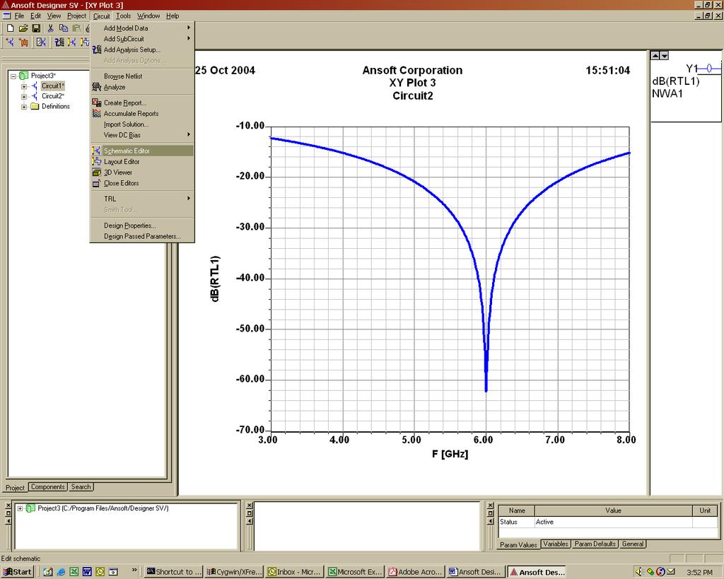
10 12. The Sweep / Value entry in the Linear Network Analysis, Frequency Domain should change to LIN 3GHz 8 GHz 10 MHz. Select Finish in the Linear Network Analysis, Frequency Domain window. You should end up back in the main program window. 11: Select Analyze from the Circuit menu to analyze the circuit. Note that the program does not give any feed back that the analysis was completed properly other than a Project 1 (C:\Program entry in the bottom left hand sub window. 13: Select Create Report from the Circuit menu to plot the response. In the Create Report dialog select OK 14. In the Traces dialog, select Return Loss as the Category, RTL1 as the Quantity, and db as the Function. Click Add Trace to add this plot to the graph. Then Done to plot the graph (See graphics next page).


11 The output should appear as below. If you wish to make changes to the circuit, go to the Circuit drop down menu, and click on Schematic Editor to bring up the circuit diagram.
12
ECE 585 Microwave Engineering II Lecture 16 Supplemental Notes. Modeling the Response of a FET Amplifier Using Ansoft Designer K.
 C 585 Microwave ngineering II Lecture 16 Supplemental Notes Modeling the Response of a FT Amplifier Using Ansoft Designer K. Carver 4-13-04 Consider a simple FT microwave amplifier circuit shown below,
K-band Waveguide BPF Design using Agilent EMPro Anurag Bhargava Application Consultant Agilent EEsof EDA
 K-band Waveguide BPF Design using Agilent EMPro 2013 Anurag Bhargava Application Consultant Agilent EEsof EDA Filter Specifications Center Frequency (Fc): 25 GHz 3dB Bandwidth: 150 MHz Rejection: 40 db
Getting Started Guide
 SOLIDWORKS Getting Started Guide SOLIDWORKS Electrical FIRST Robotics Edition Alexander Ouellet 1/2/2015 Table of Contents INTRODUCTION... 1 What is SOLIDWORKS Electrical?... Error! Bookmark not defined.
High Frequency Structure Simulator (HFSS) Tutorial
 Tutorial") High Frequency Structure Simulator (HFSS) Tutorial Prepared by Dr. Otman El Mrabet IETR, UMR CNRS 6164, INSA, 20 avenue Butte des Coësmes 35043 Rennes, FRANCE 2005-2006 TABLE OF CONTENTS INTRODUCTION...
High Frequency Structure Simulator (HFSS) Tutorial Prepared by Dr. Otman El Mrabet IETR, UMR CNRS 6164, INSA, 20 avenue Butte des Coësmes 35043 Rennes, FRANCE 2005-2006 TABLE OF CONTENTS INTRODUCTION...
ArbStudio Triggers. Using Both Input & Output Trigger With ArbStudio APPLICATION BRIEF LAB912
 ArbStudio Triggers Using Both Input & Output Trigger With ArbStudio APPLICATION BRIEF LAB912 January 26, 2012 Summary ArbStudio has provision for outputting triggers synchronous with the output waveforms
EE 210 Lab Exercise #3 Introduction to PSPICE
 EE 210 Lab Exercise #3 Introduction to PSPICE Appending 4 in your Textbook contains a short tutorial on PSPICE. Additional information, tutorials and a demo version of PSPICE can be found at the manufacturer
for Solidworks TRAINING GUIDE LESSON-9-CAD
 for Solidworks TRAINING GUIDE LESSON-9-CAD Mastercam for SolidWorks Training Guide Objectives You will create the geometry for SolidWorks-Lesson-9 using SolidWorks 3D CAD software. You will be working
Chapter 12: Electronic Circuit Simulation and Layout Software
 Chapter 12: Electronic Circuit Simulation and Layout Software In this chapter, we introduce the use of analog circuit simulation software and circuit layout software. I. Introduction So far we have designed
Creo Extrude Tutorial 2: Cutting and Adding Material
 Creo Extrude Tutorial 2: Cutting and Adding Material 1. Open Creo Parametric 2. File > Open > extrudeturial (From Creo Extrude Tutorial 1) 3. Cutting Material a. Click Extrude Icon > Select the following
Getting Started with Qucs
 Getting Started with Qucs Graham Edge University of Toronto After downloading Qucs, installing it, and running for the first time you should see a window that looks something like this: The large yellow
LAB EXERCISE 3 FET Amplifier Design and Linear Analysis
 ADS 2012 Workspaces and Simulation Tools (v.1 Oct 2012) LAB EXERCISE 3 FET Amplifier Design and Linear Analysis Topics: More schematic capture, DC and AC simulation, more on libraries and cells, using
MultiSim and Analog Discovery 2 Manual
 MultiSim and Analog Discovery 2 Manual 1 MultiSim 1.1 Running Windows Programs Using Mac Obtain free Microsoft Windows from: http://software.tamu.edu Set up a Windows partition on your Mac: https://support.apple.com/en-us/ht204009
ELE3310 Basic Electromagnetics Lab Session 1
 ELE3310 Basic Electromagnetics Lab Session 1 Gao Xin By modifying CST MICROWAVE STUDIO 2006 tutorials Geometric Construction and Solver Settings Introduction and Model Dimensions In this tutorial you will
Figure AC circuit to be analyzed.
 7.2(1) MULTISIM DEMO 7.2: INTRODUCTION TO AC ANALYSIS In this section, we ll introduce AC Analysis in Multisim. This is perhaps one of the most useful Analyses that Multisim offers, and we ll use it in
Genesys 2012 Tutorial 2 - Using Momentum Analysis for Microwave Planar Circuits: Circuit and EM Co-Simulation
 Genesys 2012 Tutorial 2 - Using Momentum Analysis for Microwave Planar Circuits: Circuit and EM Co-Simulation Here we demonstrate the process of running circuit and EM (electromagnetic) co-simulation.
This chapter shows various ways of creating matching networks by sweeping values and using optimization. Lab 5: Matching & Optimization
 5 This chapter shows various ways of creating matching networks by sweeping values and using optimization. Lab 5: Matching & Optimization OBJECTIVES Create an input match to the RF and an output match
ELC 4383 RF/Microwave Circuits I Laboratory 4: Quarter-Wave Impedance Matching Network
 1 ELC 4383 RF/Microwave Circuits I Laboratory 4: Quarter-Wave Impedance Matching Network Note: This lab procedure has been adapted from a procedure written by Dr. Larry Dunleavy and Dr. Tom Weller at the
EECS 312: Digital Integrated Circuits Lab Project 1 Introduction to Schematic Capture and Analog Circuit Simulation
 EECS 312: Digital Integrated Circuits Lab Project 1 Introduction to Schematic Capture and Analog Circuit Simulation Teacher: Robert Dick GSI: Shengshuo Lu Assigned: 5 September 2013 Due: 17 September 2013
Laboratory Assignment: EM Numerical Modeling of a Monopole
 Laboratory Assignment: EM Numerical Modeling of a Monopole Names: Objective This laboratory experiment provides a hands-on tutorial for drafting an antenna (simple monopole) and simulating radiation in
An Introductory Guide to Circuit Simulation using NI Multisim 12
 School of Engineering and Technology An Introductory Guide to Circuit Simulation using NI Multisim 12 This booklet belongs to: This document provides a brief overview and introductory tutorial for circuit
SMART 3 IN 1 HOLLYWOOD PHOTOS: SETTING UP YOUR BOOTH FOR WEDDING/EVENT MODE
 SMART 3 IN 1 HOLLYWOOD PHOTOS: SETTING UP YOUR BOOTH FOR WEDDING/EVENT MODE Start the Hollywood Photo Booth program. Rightclick anywhere on the screen and choose Setup. Click Next until you get to Screen
Excel Lab 2: Plots of Data Sets
 Excel Lab 2: Plots of Data Sets Excel makes it very easy for the scientist to visualize a data set. In this assignment, we learn how to produce various plots of data sets. Open a new Excel workbook, and
RLC Software User s Manual
 RLC Software User s Manual Venable Instruments 4201 S. Congress, Suite 201 Austin, TX 78745 512-837-2888 www.venable.biz Introduction The RLC software allows you to measure the frequency response of RLC
Entering Checkpoint Data
 Entering Checkpoint Data How do I change which Checkpoint Period I m viewing? To change the period from one to another, here are the steps: On the right side of the screen, click the grey drop-down "Change
DC Operating Point, I-V Curve Trace. Author: Nate Turner
 DC Operating Point, I-V Curve Trace Author: Nate Turner Description: This tutorial demonstrates how to print the DC-Operating Point as well as trace the I-V curves for a transistor in the tsmc 180nm process.
Recording your Voice Tutorials 2 - Setting the Computer Setting Audacity Wayne B. Dickerson
 Recording your Voice Tutorials 2 - Setting the Computer Setting Audacity Wayne B. Dickerson In this tutorial we want to insure that your computer and Audacity will do the best recording job they can do
CHAPTER 3 DESIGN OF MICROSTRIP PATCH ARRAY ANTENNA
 CHAPTER 3 DESIGN OF MICROSTRIP PATCH ARRAY ANTENNA 3.1 Introduction This chapter is discussed on the various factors that affect the design of microstrips patch array antenna. This chapter will covered
Excel Tool: Plots of Data Sets
 Excel Tool: Plots of Data Sets Excel makes it very easy for the scientist to visualize a data set. In this assignment, we learn how to produce various plots of data sets. Open a new Excel workbook, and
Microwave Circuit Design: Lab 5
 1. Introduction Microwave Circuit Design: Lab 5 This lab investigates how trade-offs between gain and noise figure affect the design of an amplifier. 2. Design Specifications IMN OMN 50 ohm source Low
REVIT - RENDERING & DRAWINGS
 TUTORIAL L-15: REVIT - RENDERING & DRAWINGS This Tutorial explains how to complete renderings and drawings of the bridge project within the School of Architecture model built during previous tutorials.
SolidWorks 103: Barge Design Challenge
 SolidWorks 103: Barge Design Challenge Note: This tutorial was created using SolidWorks 2009. If you are using another version of SolidWorks, you may notice some variation in display states and configuration.
Quick Start Guide for the PULSE PROFILING APPLICATION
 Quick Start Guide for the PULSE PROFILING APPLICATION MODEL LB480A Revision: Preliminary 02/05/09 1 1. Introduction This document provides information to install and quickly start using your PowerSensor+.
EXPERIMENT EM3 INTRODUCTION TO THE NETWORK ANALYZER
 ECE 351 ELECTROMAGNETICS EXPERIMENT EM3 INTRODUCTION TO THE NETWORK ANALYZER OBJECTIVE: The objective to this experiment is to introduce the student to some of the capabilities of a vector network analyzer.
Example Application C H A P T E R 4. Contents
 C H A P T E R 4 Example Application This chapter provides an example application of how to perform steady flow water surface profile calculations with HEC-RAS. The user is taken through a step-by-step
Drawing Layouts Paper space & Model Space
 Drawing Layouts Paper space & Model Space Users of Bricscad will have seen the tabs at the bottom left of the drawings area labelled: Model, Layout1, Layout2 but may not know how to use them or what they
Using LTSPICE to Analyze Circuits
 Using LTSPICE to Analyze Circuits Overview: LTSPICE is circuit simulation software that automatically constructs circuit equations using circuit element models (built in or downloadable). In its modern
Step 1: Set up the variables AB Design. Use the top cells to label the variables that will be displayed on the X and Y axes of the graph
 Step 1: Set up the variables AB Design Use the top cells to label the variables that will be displayed on the X and Y axes of the graph Step 1: Set up the variables X axis for AB Design Enter X axis label
Learning Guide. ASR Automated Systems Research Inc. # Douglas Crescent, Langley, BC. V3A 4B6. Fax:
 Learning Guide ASR Automated Systems Research Inc. #1 20461 Douglas Crescent, Langley, BC. V3A 4B6 Toll free: 1-800-818-2051 e-mail: support@asrsoft.com Fax: 604-539-1334 www.asrsoft.com Copyright 1991-2013
Activity P52: LRC Circuit (Voltage Sensor)
") Activity P52: LRC Circuit (Voltage Sensor) Concept DataStudio ScienceWorkshop (Mac) ScienceWorkshop (Win) AC circuits P52 LRC Circuit.DS (See end of activity) (See end of activity) Equipment Needed Qty
Activity P52: LRC Circuit (Voltage Sensor) Concept DataStudio ScienceWorkshop (Mac) ScienceWorkshop (Win) AC circuits P52 LRC Circuit.DS (See end of activity) (See end of activity) Equipment Needed Qty
PSPICE T UTORIAL P ART I: INTRODUCTION AND DC ANALYSIS. for the Orcad PSpice Release 9.2 Lite Edition
 PSPICE T UTORIAL P ART I: INTRODUCTION AND DC ANALYSIS for the Orcad PSpice Release 9.2 Lite Edition INTRODUCTION The Simulation Program with Integrated Circuit Emphasis (SPICE) circuit simulation tool
Introduction to PSpice
 Electric Circuit I Lab Manual 4 Session # 5 Introduction to PSpice 1 PART A INTRODUCTION TO PSPICE Objective: The objective of this experiment is to be familiar with Pspice (learn how to connect circuits,
Chapter 6 Title Blocks
 Chapter 6 Title Blocks In previous exercises, every drawing started by creating a number of layers. This is time consuming and unnecessary. In this exercise, we will start a drawing by defining layers
Materials Tutorial. Chapter 6: Setting Materials Defaults
 Setting Materials Defaults Chapter 6: Materials Tutorial Materials display on the surfaces of objects in 3D views and can make a 3D view appear highly realistic. When applied to most objects, material
Use of the LTI Viewer and MUX Block in Simulink
 Use of the LTI Viewer and MUX Block in Simulink INTRODUCTION The Input-Output ports in Simulink can be used in a model to access the LTI Viewer. This enables the user to display information about the magnitude
Converting a solid to a sheet metal part tutorial
 Converting a solid to a sheet metal part tutorial Introduction Sometimes it is easier to start with a solid and convert it to create a sheet metal part. This tutorial will guide you through the process
ADS Application Notes. The Components Characterization Using ADS
 ADS Application Notes Wireless ommunication aboratory Department of Electrical and Electronic Engineering Hong Kong University of Science and Technology The omponents haracterization Using ADS Introduction
Using SERENADE 8.7 Design Suite to design 435/145 MHz contiguous diplexer filter
 REVISED: 01.06.2011. DESIGN EXAMPLES DE #1 Using SERENADE 8.7 Design Suite to design 435/145 MHz contiguous diplexer filter By Dipl. Ing. Gyula Nagy, HA8ET This article illustrates the design and development
Engineering 3821 Fall Pspice TUTORIAL 1. Prepared by: J. Tobin (Class of 2005) B. Jeyasurya E. Gill
 B. Jeyasurya E. Gill") Engineering 3821 Fall 2003 Pspice TUTORIAL 1 Prepared by: J. Tobin (Class of 2005) B. Jeyasurya E. Gill 2 INTRODUCTION The PSpice program is a member of the SPICE (Simulation Program with Integrated Circuit
Engineering 3821 Fall 2003 Pspice TUTORIAL 1 Prepared by: J. Tobin (Class of 2005) B. Jeyasurya E. Gill 2 INTRODUCTION The PSpice program is a member of the SPICE (Simulation Program with Integrated Circuit
Experiment 1 Half-wave dipole
 Experiment 1 Half-wave dipole In this work we will simulate a half-wave antenna in free space, comparing the results obtained via the simulation with the theoretical ones. We will analyze the variations
Excel Manual X Axis Label Below Chart 2010 >>>CLICK HERE<<<
 Excel Manual X Axis Label Below Chart 2010 When the X-axis is crowded with labels one way to solve the problem is to split the labels for to use two rows of labels enter the two rows of X-axis labels as
This tutorial will lead you through step-by-step to make the plot below using Excel.
 GES 131 Making Plots with Excel 1 / 6 This tutorial will lead you through step-by-step to make the plot below using Excel. Number of Non-Student Tickets vs. Student Tickets Y, Number of Non-Student Tickets
Sheet Metal Punch ifeatures
 Lesson 5 Sheet Metal Punch ifeatures Overview This lesson describes punch ifeatures and their use in sheet metal parts. You use punch ifeatures to simplify the creation of common and specialty cut and
LAB 8: Activity P52: LRC Circuit
 LAB 8: Activity P52: LRC Circuit Equipment: Voltage Sensor 1 Multimeter 1 Patch Cords 2 AC/DC Electronics Lab (100 μf capacitor; 10 Ω resistor; Inductor Coil; Iron core; 5 inch wire lead) The purpose of
Passive Circuit DesignGuide
 Passive Circuit DesignGuide August 2005 Notice The information contained in this document is subject to change without notice. Agilent Technologies makes no warranty of any kind with regard to this material,
Materials Tutorial. Setting Materials Defaults
 Materials Tutorial Materials display on the surfaces of objects in 3D views and can make a 3D view appear highly realistic. When applied to most objects, material quantities will also be calculated in
Exercise 1. Milling a Part with the Lab-Volt CNC Mill EXERCISE OBJECTIVE
 Exercise 1 Milling a Part with the Lab-Volt CNC Mill EXERCISE OBJECTIVE When you have completed this exercise, you will be able to engrave text on square pieces of stock, using the Lab-Volt CNC Mill, model
Unit. Drawing Accurately OVERVIEW OBJECTIVES INTRODUCTION 8-1
 8-1 Unit 8 Drawing Accurately OVERVIEW When you attempt to pick points on the screen, you may have difficulty locating an exact position without some type of help. Typing the point coordinates is one method.
Page 21 GRAPHING OBJECTIVES:
 Page 21 GRAPHING OBJECTIVES: 1. To learn how to present data in graphical form manually (paper-and-pencil) and using computer software. 2. To learn how to interpret graphical data by, a. determining the
Time Domain Reflectometer Example
 Time Domain Reflectometer Example This section presents differential and single-ended versions of a Time Domain Reflectometer (TDR). The setup demonstrates the process of analyzing both imdepance and delay.
EXPERIMENT NUMBER 10 TRANSIENT ANALYSIS USING PSPICE
 EXPERIMENT NUMBER 10 TRANSIENT ANALYSIS USING PSPICE Objective: To learn to use a circuit simulator package for plotting the response of a circuit in the time domain. Preliminary: Revise laboratory 8 to
LT Spice Getting Started Very Quickly. First Get the Latest Software!
 LT Spice Getting Started Very Quickly First Get the Latest Software! 1. After installing LT Spice, run it and check to make sure you have the latest version with respect to the latest version available
Introduction to Autodesk Inventor for F1 in Schools (Australian Version)
") Introduction to Autodesk Inventor for F1 in Schools (Australian Version) F1 in Schools race car In this course you will be introduced to Autodesk Inventor, which is the centerpiece of Autodesk s Digital
Introduction to Autodesk Inventor for F1 in Schools (Australian Version) F1 in Schools race car In this course you will be introduced to Autodesk Inventor, which is the centerpiece of Autodesk s Digital
Multilayer VIA simulations using ADS Anurag Bhargava, Application Consultant, Agilent EEsof EDA, Agilent Technologies
 Multilayer VIA simulations using ADS Anurag Bhargava, Application Consultant, Agilent EEsof EDA, Agilent Technologies Many a time designers find themselves in pretty confusing start when it comes to simulating
Prasanth. Lathe Machining
 Lathe Machining Overview Conventions What's New? Getting Started Open the Part to Machine Create a Rough Turning Operation Replay the Toolpath Create a Groove Turning Operation Create Profile Finish Turning
Instruction Manual for the Software of ASSAN V2 Series Receiver
 Instruction Manual for the Software of ASSAN V2 Series Receiver I. Setup 1. Double click SETUP to enter the welcome interface and click Next. 2. Enter your name and company name and click Next. 3. Select
Large-Signal S-Parameter Simulation
 Large-Signal S-Parameter Simulation May 2003 Notice The information contained in this document is subject to change without notice. Agilent Technologies makes no warranty of any kind with regard to this
Tiling. 1. Overlapping tiles with fixed number of tiles. Tutorial
 Tutorial Tiling Software version: Asanti 3.0 Document version: April 3, 2017 This tutorial demonstrates how to use tiling within Asanti. Download the Asanti Sample Files via the Asanti Client (Help > Asanti
AWR. imatch White Paper. Overview. Intelligent & Automated Impedance Matching Module
 Overview One of the most common tasks required of an RF engineer is basic impedance matching. AWR s Microwave Office software has included this ability for a long time now via a manual step through matching
Submittals Quick Reference Guide
 This topic provides a reference for the Project Center Submittals activity center. Purpose The Submittals activity center in Newforma Contract Management enables you to effectively log submittals and track
NCSS Statistical Software
 Chapter 147 Introduction A mosaic plot is a graphical display of the cell frequencies of a contingency table in which the area of boxes of the plot are proportional to the cell frequencies of the contingency
Large-Signal S-Parameter Simulation
 Large-Signal S-Parameter Simulation September 2004 Notice The information contained in this document is subject to change without notice. Agilent Technologies makes no warranty of any kind with regard
Principles and Practice
 Principles and Practice An Integrated Approach to Engineering Graphics and AutoCAD 2011 Randy H. Shih Oregon Institute of Technology SDC PUBLICATIONS www.sdcpublications.com Schroff Development Corporation
Table of Contents. Chapter 1: Software Installation...1. Chapter 2: Running the Software II. Daily Practical Operation...10
 Product Manual Table of Contents Chapter 1: Software Installation.................................1 Chapter 2: Running the Software............................... 2 I. The Initial Defining in Lock Management
Input of Precise Geometric Data
 Chapter Seven Input of Precise Geometric Data INTRODUCTION PLAY VIDEO A very useful feature of MicroStation V8i for precise technical drawing is key-in of coordinate data. Whenever MicroStation V8i calls
CAD Tutorial. CAD Detail Windows. In this tutorial you ll learn about: CAD Detail Windows Exploding and Modifying a CAD Block
 CAD Tutorial In this tutorial you ll learn about: CAD Detail Windows Exploding and Modifying a CAD Block Creating a New CAD Block CAD Detail from View Creating a Plot Plan CAD Detail Windows CAD Details
Introduction to NI Multisim & Ultiboard Software version 14.1
 School of Engineering and Applied Science Electrical and Computer Engineering Department Introduction to NI Multisim & Ultiboard Software version 14.1 Dr. Amir Aslani August 2018 Parts Probes Tools Outline
Lab 9 Frequency Domain
 Lab 9 Frequency Domain 1 Components Required Resistors Capacitors Function Generator Multimeter Oscilloscope 2 Filter Design Filters are electric components that allow applying different operations to
CREATING (AB) SINGLE- SUBJECT DESIGN GRAPHS IN MICROSOFT EXCEL Lets try to graph this data
 SINGLE- SUBJECT DESIGN GRAPHS IN MICROSOFT EXCEL Lets try to graph this data") CREATING (AB) SINGLE- SUBJECT DESIGN GRAPHS IN MICROSOFT EXCEL 2003 Lets try to graph this data Date Baseline Data Date NCR (intervention) 11/10 11/11 11/12 11/13 2 3 3 1 11/15 11/16 11/17 11/18 3 3 2
CREATING (AB) SINGLE- SUBJECT DESIGN GRAPHS IN MICROSOFT EXCEL 2003 Lets try to graph this data Date Baseline Data Date NCR (intervention) 11/10 11/11 11/12 11/13 2 3 3 1 11/15 11/16 11/17 11/18 3 3 2
Adding Objects Creating Shapes Adding. Getting Started Creating a Workspace Pages, Masters and Guides Adding Objects Creating Shapes Adding
 and Guides ILLUSTRATOR Adding Objects Creating Shapes Adding Getting Started WORKSHOP: Creating a Workspace Pages, Masters Workspace Pages, ADVANCED Masters and Guides Adding Objects WORKSHOP OBJECTIVES
Xcalibur. LCquan. Tutorial. Quantitative Analysis of a Three-Drugs Data Set Software Version 2.8
 Xcalibur LCquan Tutorial Quantitative Analysis of a Three-Drugs Data Set Software Version 2.8 XCALI-97547 Revision A April 2013 2013 Thermo Fisher Scientific Inc. All rights reserved. LCquan, DCMS Link,
ELC RF/Microwave Circuits I Laboratory 6: Quadrature Hybrid Coupler
 1 ELC 4383 -RF/Microwave Circuits I Laboratory 6: Quadrature Hybrid Coupler Note: This lab procedure has been adapted from a procedure written by Dr. Larry Dunleavy and Dr. Tom Weller at the University
Background Theory and Simulation Practice
 CAD and Simulation Objectives Experiment Topic: CAD and Simulation PSpice 9.1 Student Version To obtain your free copy of the software and user s guide, go to Electronics Lab website ( http://www.electronics-lab.com/downloads/schematic/013/
ECE4902 Lab 5 Simulation. Simulation. Export data for use in other software tools (e.g. MATLAB or excel) to compare measured data with simulation
 to compare measured data with simulation") ECE4902 Lab 5 Simulation Simulation Export data for use in other software tools (e.g. MATLAB or excel) to compare measured data with simulation Be sure to have your lab data available from Lab 5, Common
ECE4902 Lab 5 Simulation Simulation Export data for use in other software tools (e.g. MATLAB or excel) to compare measured data with simulation Be sure to have your lab data available from Lab 5, Common
State of Florida Department of Transportation. FDOT Traffic Plans. Signing & Pavement Markings (CE ) Signalization (CE ) Lighting
 Signalization (CE ) Lighting") State of Florida Department of Transportation FDOT Traffic Plans Signing & Pavement Markings (CE-11-0117) Signalization (CE-11-0119) Lighting (CE-11-0118) User Training Manual October 2017 PRODUCTION SUPPORT
State of Florida Department of Transportation FDOT Traffic Plans Signing & Pavement Markings (CE-11-0117) Signalization (CE-11-0119) Lighting (CE-11-0118) User Training Manual October 2017 PRODUCTION SUPPORT
BIO 365L Neurobiology Laboratory. Training Exercise 1: Introduction to the Computer Software: DataPro
 BIO 365L Neurobiology Laboratory Training Exercise 1: Introduction to the Computer Software: DataPro 1. Don t Panic. When you run DataPro, you will see a large number of windows, buttons, and boxes. In
LTSpice Basic Tutorial
 Index: I. Opening LTSpice II. Drawing the circuit A. Making Sure You Have a GND B. Getting the Parts C. Placing the Parts D. Connecting the Circuit E. Changing the Name of the Part F. Changing the Value
SIMULATION OF A SERIES RESONANT CIRCUIT ECE562: Power Electronics I COLORADO STATE UNIVERSITY. Modified in Fall 2011
 SIMULATION OF A SERIES RESONANT CIRCUIT ECE562: Power Electronics I COLORADO STATE UNIVERSITY Modified in Fall 2011 ECE 562 Series Resonant Circuit (NL5 Simulation) Page 1 PURPOSE: The purpose of this
ECE 201 LAB 6 INTRODUCTION TO SPICE/PSPICE
 Version 1.1 1 of 33 BEFORE YOU BEGIN PREREQUISITE LABS Resistive Circuits EXPECTED KNOWLEDGE ECE 201 LAB 6 INTRODUCTION TO SPICE/PSPICE Ohm's Law: v = ir Node Voltage and Mesh Current Methods of Circuit
Switching to Sub Category and Collapsible Skins
 Switching to Sub Category and Collapsible Skins New programming enhancements and features are not compatible with the older Q-Net skins. If you are using either the original Drop Down skin or the Standard
Creating Photo Borders With Photoshop Brushes
 Creating Photo Borders With Photoshop Brushes Written by Steve Patterson. In this Photoshop photo effects tutorial, we ll learn how to create interesting photo border effects using Photoshop s brushes.
Toothbrush Holder. A drawing of the sheet metal part will also be created.
 Prerequisite Knowledge Previous knowledge of the following commands is required to complete this lesson; Sketch (Line, Centerline, Circle, Add Relations, Smart Dimension,), Extrude Boss/Base, and Edit
Lesson 10: Loft Features
 10 Goals of This Lesson Your students will be able to create the following part: profiles chisel This lesson plan corresponds to the Loft Features chapter of SolidWorks Getting Started. SolidWorks Student
Anchor Block Draft Tutorial
 Anchor Block Draft Tutorial In the following tutorial you will create a drawing of the anchor block shown. The tutorial covers such topics as creating: Orthographic views Section views Auxiliary views
Rhinoceros modeling tools for designers. Using Layouts in Rhino 5
 Rhinoceros modeling tools for designers Using Layouts in Rhino 5 RH50-TM-LAY-Apr-2014 Rhinoceros v5.0, Layouts, Training Manual Revised April 8, 2014, Mary Fugier mary@mcneel.com Q&A April 8, 2014, Lambertus
Figure Main frame of IMNLab.
 IMNLab Tutorial This Tutorial guides the user to go through the design procedure of a wideband impedance match network for a real circuit by using IMNLab. Wideband gain block TQP3M97 evaluation kit from
Qucs. A Tutorial. Getting Started with Qucs. Stefan Jahn Juan Carlos Borrás
 Qucs A Tutorial Getting Started with Qucs Stefan Jahn Juan Carlos Borrás Copyright c 2007 Stefan Jahn Copyright c 2007 Juan Carlos Borrás Permission is granted to
The CReSIS Anechoic Chamber is located at: The University of Kansas. M2SEC building W 15 th St. Lawrence, KS
 The CReSIS Anechoic Chamber is located at: The University of Kansas M2SEC building 1536 W 15 th St Lawrence, KS 66045 Pattern Manual Antenna radiation pattern measurement 1. To open EMQuest, right click
FOCUS ON REAL DESIGN AUTOMATE THE REST CUSTOMTOOLS BATCH CONVERTING YOUR SOLIDWORKS FILES
 FOCUS ON REAL DESIGN AUTOMATE THE REST CUSTOMTOOLS BATCH CONVERTING YOUR SOLIDWORKS FILES Table of Contents BATCH CONVERTING YOUR SOLIDWORKS DOCUMENTS... 3 Introduction... 3 What does it do?... 3 How does
Modeling Basic Mechanical Components #1 Tie-Wrap Clip
 Modeling Basic Mechanical Components #1 Tie-Wrap Clip This tutorial is about modeling simple and basic mechanical components with 3D Mechanical CAD programs, specifically one called Alibre Xpress, a freely