Electromagnetic, Thermal and Structural Analysis of the LUX Photoinjector Cavity using ANSYS. Steve Virostek Lawrence Berkeley National Lab
|
|
|
- Dale Logan
- 5 years ago
- Views:
Transcription
1 Electromagnetic, Thermal and Structural Analysis of the LUX Photoinjector Cavity using ANSYS Steve Virostek Lawrence Berkeley National Lab 13 December 2004
2 Photoinjector Background The proposed LBNL LUX project is a linac/laser based, femtosecond-regime X-ray facility The photoinjector is a room-temperature 1.3 GHz 4 cell structure producing a 10 MeV, nominal 30 psec, 1 nanocoulomb electron bunch at a 10 khz rate The first cell is of reentrant geometry, with a peak field of 64 MV/m at the photocathode surface The high repetition rate and high peak power results in a high average surface power density The RF system will be designed to provide a short, high-power driving pulse and active removal of stored energy after the beam pulse to reduce the average power dissipated in the cavity
3 Photoinjector Vacuum Wall
4 Relevant Publications J.W. Staples, S.P. Virostek and S.M. Lidia, Engineering Design of the LUX Photoinjector, EPAC 2004 Description of the configuration and operating parameters of Cell 1 of the LUX photoinjector. Details and results of the RF, thermal and structural modeling of the cavity are provided including a discussion of cavity frequency shift due to loading conditions. N. Hartman and R.A. Rimmer, Electromagnetic, Thermal, and Structural Analysis of RF Cavities using ANSYS, PAC 2001 Report on technique for combined cavity analysis. Methods for importing CAD solid models and creating an acceptable mesh are discussed. A mesh sensitivity study is presented as well. The modeling method is applied to a proposed cavity for the NLC damping rings.
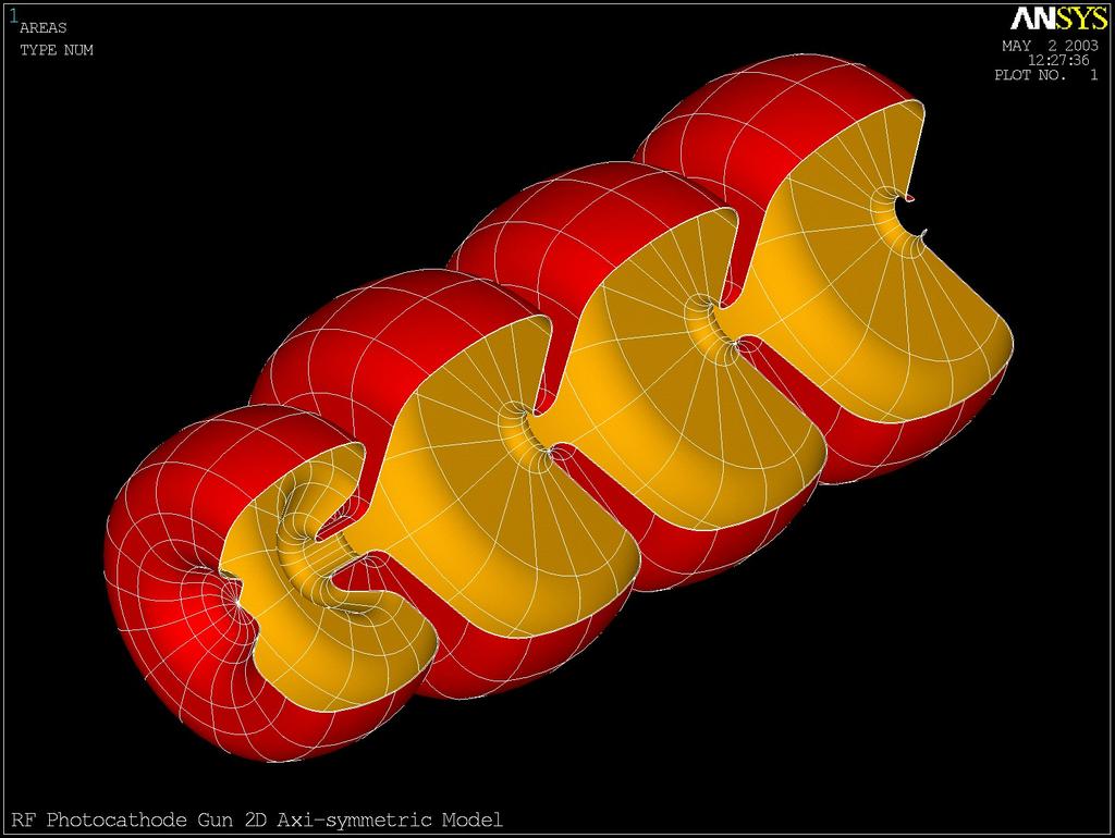
5 Analysis Methodology RF Modeling Initial phase of the analysis entails performing a high frequency electromagnetic analysis of the cavity vacuum volume Model run time is reduced by taking advantage of cavity symmetry Vacuum volume is meshed with tetrahedral RF elements (HF119) with a finer mesh in areas of high fields Electric wall and impedance boundary conditions are applied to exterior surfaces representing the cavity wall-to-vacuum interfaces Model symmetry planes default to magnetic walls A modal RF analysis is run resulting in calculation of the cavity frequency and Q as well as normalized data for the E and H fields

6 Cavity RF Model Mesh

7 Normalized E-Field along Cavity Axis
8 Analysis Methodology Heat Flux The initial step in developing the thermal model is to generate a new mesh on the cavity surface that matches node-for-node the mesh on the surface of the RF model The new mesh consists of surface effect elements (SURF 152) without mid-side nodes and with heat flux loading capability Next, a macro consisting of an input file with a sequential list of ANSYS commands reads in the H field at each surface node The total cavity wall heat flux is found by summing ½ R S H 2 da over all surface nodes - R S : surface resistance, H: normalized magnetic field, da: based on the element areas adjacent to nodes The results are scaled based on the known total heat loss in the cavity (31 kw in this case) and applied to the new surface elements


9 Calculated Wall Heat Flux
10 Analysis Methodology Thermal Modeling Thermal analysis begins by deleting the original RF elements, leaving only the new surface elements with applied heat fluxes A solid model representing a conceptual design of the actual cavity walls is constructed around the existing surface elements The model includes relevant features: cooling passages, ports, etc. Upon meshing with the appropriate thermal elements, heat fluxes from the surface mesh are automatically mapped onto the model Heat balance is achieved by applying convective cooling to the surfaces of the water passages Solution of the thermal model results in nodal temperature results throughout the cavity walls (peak temperature reached is 87ºC)

11 Cell 1 Cavity Wall 1/4 Model

12 Cavity Thermal Solution Temperature ºC
13 Analysis Methodology Structural Modeling ANSYS allows direct solution of the structural problem by converting the thermal elements to equivalent structural elements The temperature data obtained from the thermal solution can be automatically applied as a load on the structural model Vacuum loads, symmetry boundary conditions and cavity support constraints are applied to the model as well The peak von Mises stress in the photoinjector was found to be approximately 65 Mpa Care must be taken when initially defining the mesh density of the RF model since mesh on the cavity wall surfaces will remain unchanged during RF, thermal and structural modeling
14 Cavity Stress Solution Stress, MPa
15 Analysis Methodology Frequency Shift Cavity wall displacements due to the loading conditions, including thermal distortion, are also obtained from the structural solution Nodal displacements at the cavity/vacuum interface, taken at the symmetry plane without the iris coupler, are added to the original nodal locations to yield a 2-D profile of the displaced cavity shape A new RF model based on the displaced profile is used to predict frequency shift due to various loading and thermal conditions To verify the procedure, the model was run again with the only change being to the cooling water temperature Resulting frequency shift: khz/ºc T in water temperature Agrees to within 0.5% of the expected sensitivity based on the product of the nominal cavity frequency and the cavity material α
A Design Study of a 100-MHz Thermionic RF Gun for the ANL XFEL-O Injector
 A Design Study of a 100-MHz Thermionic RF Gun for the ANL XFEL-O Injector A. Nassiri Advanced Photon Source For ANL XFEL-O Injector Study Group M. Borland (ASD), B. Brajuskovic (AES), D. Capatina (AES),
Normal-Conducting Photoinjector for High Power CW FEL
 LA-UR-04-5617,-5808 www.arxiv.org: physics/0404109 Normal-Conducting Photoinjector for High Power CW FEL Sergey Kurennoy, LANL, Los Alamos, NM, USA An RF photoinjector capable of producing high continuous
RF Design of Normal Conducting Deflecting Cavity
 RF Design of Normal Conducting Deflecting Cavity Valery Dolgashev (SLAC), Geoff Waldschmidt, Ali Nassiri (Argonne National Laboratory, Advanced Photon Source) 48th ICFA Advanced Beam Dynamics Workshop
1.5 GHz Cavity design for the Clic Damping Ring and as Active Third Harmonic cavity for ALBA.
 1 1.5 GHz Cavity design for the Clic Damping Ring and as Active Third Harmonic cavity for ALBA. Beatriz Bravo Overview 2 1.Introduction 2.Active operation 3.Electromagnetic design 4.Mechanical design Introduction
RF thermal and new cold part design studies on TTF-III input coupler for Project-X
 RF thermal and new cold part design studies on TTF-III input coupler for Project-X PEI Shilun( 裴士伦 ) 1; 1) Chris E Adolphsen 2 LI Zenghai( 李增海 ) 2 Nikolay A Solyak 3 Ivan V Gonin 3 1 Institute of High
THE ORION PHOTOINJECTOR: STATUS and RESULTS
 THE ORION PHOTOINJECTOR: STATUS and RESULTS Dennis T. Palmer SLAC / ARDB ICFA Sardinia 4 July 2002 1. Introduction 2. Beam Dynamics Simulations 3. Photoinjector 1. RF Gun 2. Solenoidal Magnet 3. Diagnostics
CST MWS simulation of the SARAF RFQ 1.5 MeV/nucleon proton/deuteron accelerator
 CST MWS simulation of the SARAF RFQ 1.5 MeV/nucleon proton/deuteron accelerator Jacob Rodnizki SARAF Soreq NRC APril 19-21 th, 2010 Outline 1. SARAF accelerator 2. Presentation of the four rods RFQ 3.
Behavior of the TTF2 RF Gun with long pulses and high repetition rates
 Behavior of the TTF2 RF Gun with long pulses and high repetition rates J. Baehr 1, I. Bohnet 1, J.-P. Carneiro 2, K. Floettmann 2, J. H. Han 1, M. v. Hartrott 3, M. Krasilnikov 1, O. Krebs 2, D. Lipka
Status of Coil Structural Design and Magnetic-Structural Analysis
 Status of Coil Structural Design and Magnetic-Structural Analysis Presented by X.R. Wang Contributors: ORNL: D. Williamson UCSD: S. Malang, A.R. Raffray UW: C. Martin ARIES Meeting UC San Diego, San Diego
Design and RF Measurements of an X-band Accelerating Structure for the Sparc Project
 Design and RF Measurements of an X-band Accelerating Structure for the Sparc Project INFN-LNF ; UNIVERSITY OF ROME LA SAPIENZA ; INFN - MI Presented by BRUNO SPATARO Erice, Sicily, October 9-14; 2005 SALAF
Fundamental mode rejection in SOLEIL dipole HOM couplers
 Fundamental mode rejection in SOLEIL dipole HOM couplers G. Devanz, DSM/DAPNIA/SACM, CEA/Saclay, 91191 Gif-sur-Yvette 14th June 2004 1 Introduction The SOLEIL superconducting accelerating cavity is a heavily
RF design studies of 1300 MHz CW buncher for European X-FEL. Shankar Lal PITZ DESY-Zeuthen
 RF design studies of 1300 MHz CW buncher for European X-FEL Shankar Lal PITZ DESY-Zeuthen Outline Introduction Buncher design: Literature survey RF design of two-cell buncher: First design Two- cell buncher:
CEBAF waveguide absorbers. R. Rimmer for JLab SRF Institute
 CEBAF waveguide absorbers R. Rimmer for JLab SRF Institute Outline Original CEBAF HOM absorbers Modified CEBAF loads for FEL New materials for replacement loads High power loads for next generation FELs
BESSY VSR: SRF challenges and developments for a variable pulse-length next generation light source
 BESSY VSR: SRF challenges and developments for a variable pulse-length next generation light source Institut SRF - Wissenschaft und Technologie (FG-ISRF) Adolfo Vélez et al. SRF17 Lanzhou, 17-21/7/2017
MHz NCRF R&D Program and Plans. R. Rimmer, A. Ladran, D. Li LBNL
 201.25 MHz NCRF R&D Program and Plans R. Rimmer, A. Ladran, D. Li LBNL 201.25 MHz cavity design status RF parameters for MICE Components Proposed manufacturing plan Fabrication tests Foils and grids Forces
Status of the HOM Damped Cavity Project
 Status of the HOM Damped Cavity Project E. Weihreter / BESSY for the HOM Damped Cavity Collaboration BESSY, Daresbury Lab, DELTA, MaxLab, NTHU Project funded by the EC under contract HPRI-CT-1999-50011
3.9 GHz Deflecting Mode Cavity
 3.9 GHz Deflecting Mode Cavity Timothy W. Koeth July 12, 2005 History of 3.9 GHz DMC Cavity Simulations The Other Modes concern and modeling R/Q Wake Field Simulations Design: OM couplers Testing: Vertical
Third Harmonic Cavity Status
 Third Harmonic Cavity Status General parameters Cavity design Main coupler calculation HOM analysis and HOM coupler design Lorentz Forces and Stress analysis Summary General parameters Third harmonic cavity
The design of a radio frequency quadrupole LINAC for the RIB project at VECC Kolkata
 PRAMANA cfl Indian Academy of Sciences Vol. 59, No. 6 journal of December 2002 physics pp. 957 962 The design of a radio frequency quadrupole LINAC for the RIB project at VECC Kolkata V BANERJEE 1;Λ, ALOK
LOW-β SC RF CAVITY INVESTIGATIONS
 LOW-β SC RF CAVITY INVESTIGATIONS E. Zaplatin, W. Braeutigam, R. Stassen, FZJ, Juelich, Germany Abstract At present, many accelerators favour the use of SC cavities as accelerating RF structures. For some
Evaluation of HOM Coupler Probe Heating by HFSS Simulation
 G. Wu, H. Wang, R. A. Rimmer, C. E. Reece Abstract: Three different tip geometries in a HOM coupler on a CEBAF Upgrade Low Loss cavity have been evaluated by HFSS simulation to understand the tip surface
Design, Development and Testing of RF Window for C band 250 kw CW Power Klystron
 Available online www.ejaet.com European Journal of Advances in Engineering and Technology, 2016, 3(6): 26-30 Research Article ISSN: 2394-658X Design, Development and Testing of RF Window for C band 250
DEVELOPMENT OF A BETA 0.12, 88 MHZ, QUARTER WAVE RESONATOR AND ITS CRYOMODULE FOR THE SPIRAL2 PROJECT
 DEVELOPMENT OF A BETA 0.12, 88 MHZ, QUARTER WAVE RESONATOR AND ITS CRYOMODULE FOR THE SPIRAL2 PROJECT G. Olry, J-L. Biarrotte, S. Blivet, S. Bousson, C. Commeaux, C. Joly, T. Junquera, J. Lesrel, E. Roy,
Electromagnetic and thermal model for Brushless PM motors
 22 December 2017 Motor-CAD Software Tutorial: Electromagnetic and thermal model for Brushless PM motors Contents 1. Description... 1 2. Model Definition... 2 3. Machine Geometry... 3 4. Winding Definition...
ACE3P and Applications to HOM Power Calculation in Cornell ERL
 ACE3P and Applications to HOM Power Calculation in Cornell ERL Liling Xiao Advanced Computations Group SLAC National Accelerator Laboratory HOM10 Workshop, Cornell, October 11-13, 2010 Work supported by
Design of the 352MHz, beta 0.50, Double- Spoke Cavity for ESS
 Design of the 352MHz, beta 0.50, Double- Spoke Cavity for ESS Patricia DUCHESNE, Guillaume OLRY Sylvain BRAULT, Sébastien BOUSSON, Patxi DUTHIL, Denis REYNET Institut de Physique Nucléaire d Orsay SRF
The BESSY Higher Order Mode Damped Cavity - Further Improvements -
 The BESSY Higher Order Mode Damped Cavity - Further Improvements - Ernst Weihreter Reminder of Technical Problems Solutions Conclusions BESSY HOM Damped Cavity Project collaboration: (EC funded) - BESSY
SC Cavity Development at IMP. Linac Group Institute of Modern Physics, CAS IHEP, Beijing,CHINA
 SC Cavity Development at IMP Linac Group Institute of Modern Physics, CAS 2011-09-19 IHEP, Beijing,CHINA Outline Ø Superconducting Cavity Choice Ø HWR Cavity Design EM Design & optimization Mechanical
Status of the APEX Project at LBNL
 at LBNL Fernando Sannibale K. Baptiste, B. Bailey, D. Colomb, C. Cork, J. Corlett, S. De Santis, J. Feng, D. Filippetto, G.Huang, R. Kraft, S. Kwiatkowski, D. Li, M. Messerly, R. Muller, W. E. Norum, H.
ISG3 Injector Working Group (WG2) l/26/99. NLC Damping Ring RF Cavity development. R. A. Rimmer LBNL
 l/26/99. NLC Damping Ring RF Cavity development. R. A. Rimmer LBNL") ISG3 Injector Working Group (WG2) l/26/99 NLC Damping Ring RF Cavity development R. A. Rimmer LBNL outline: Parameters Baseline design (scaled PEP-II) R&D HOM damping waveguides HOM loads Window and Coupler
ISG3 Injector Working Group (WG2) l/26/99 NLC Damping Ring RF Cavity development R. A. Rimmer LBNL outline: Parameters Baseline design (scaled PEP-II) R&D HOM damping waveguides HOM loads Window and Coupler
Resonant Excitation of High Order Modes in the 3.9 GHz Cavity of LCLS-II Linac
 Resonant Excitation of High Order Modes in the 3.9 GHz Cavity of LCLS-II Linac LCLS-II TN-16-05 9/12/2016 A. Lunin, T. Khabiboulline, N. Solyak, A. Sukhanov, V. Yakovlev April 10, 2017 LCLSII-TN-16-06
CHAPTER 2 ELECTROMAGNETIC FORCE AND DEFORMATION
 18 CHAPTER 2 ELECTROMAGNETIC FORCE AND DEFORMATION 2.1 INTRODUCTION Transformers are subjected to a variety of electrical, mechanical and thermal stresses during normal life time and they fail when these
Noise and Vibration Prediction in Shunt- Reactor using Fluid Structure Interaction Technique
 Noise and Vibration Prediction in Shunt- Reactor using Fluid Structure Interaction Technique by PARMATMA DUBEY CROMPTON GREAVES LTD. parmatma.dubey@cgglobal.com and VIJENDRA GUPTA CROMPTON GREAVES LTD.
IAP 2007 Engineering Design and Rapid Prototyping. January 28, 2007 Version 1.3. Deliverable C. CAD Model and Performance Analysis
 16.810 IAP 2007 Engineering Design and Rapid Prototyping January 28, 2007 Version 1.3 Deliverable C CAD Model and Performance Analysis System: MIT Space Elevator Team Beamed Ribbon Climber Component or
Pulsed 5 MeV standing wave electron linac for radiation processing
 PHYSICAL REVIEW SPECIAL TOPICS - ACCELERATORS AND BEAMS, VOLUME 7, 030101 (2004) Pulsed 5 MeV standing wave electron linac for radiation processing L. Auditore, R. C. Barnà, D. De Pasquale, A. Italiano,
Progress in High Gradient Accelerator Research at MIT
 Progress in High Gradient Accelerator Research at MIT Presented by Richard Temkin MIT Physics and Plasma Science and Fusion Center May 23, 2007 MIT Accelerator Research Collaborators MIT Plasma Science
Cavity BPM With Dipole-Mode Selective Coupler
 Cavity BPM With Dipole-Mode Selective Coupler Zenghai Li Advanced Computations Department Stanford Linear Accelerator Center Presented at PAC23 Portland, Oregon. May 12-16, 23 Work supported by the U.S.
The Naim Balanced Mode Radiator The Naim Ovator Bass Driver
 1 The Naim Balanced Mode Radiator The Naim Ovator Bass Driver Lampos Ferekidis & Karl-Heinz Fink Fink Audio Consulting on behalf of Naim Audio Southampton Road, Salisbury SP1 2LN, ENGLAND The Balanced
Project X Cavity RF and mechanical design. T. Khabiboulline, FNAL/TD/SRF
 Project X Cavity RF and mechanical design T. Khabiboulline, FNAL/TD/SRF TTC meeting on CW-SRF, 2013 Project X Cavity RF and mechanical design T 1 High ß Low ß 0.5 HWR SSR1 SSR2 0 1 10 100 1 10 3 1 10 4
Motor-CAD winding temperature model verification using Finite Element Analysis
 Motor-CAD winding temperature model verification using Finite Element Analysis Description Motor-CAD uses a layered model, where the copper, insulation and impregnation are evenly distributed through the
Abaqus Beam Tutorial (ver. 6.12)
") Abaqus Beam Tutorial (ver. 6.12) Problem Description The two-dimensional bridge structure is simply supported at its lower corners. The structure is composed of steel T-sections (E = 210 GPa, ν = 0.25)
Abaqus Beam Tutorial (ver. 6.12) Problem Description The two-dimensional bridge structure is simply supported at its lower corners. The structure is composed of steel T-sections (E = 210 GPa, ν = 0.25)
A study of Vibration Analysis for Gearbox Casing Using Finite Element Analysis
 A study of Vibration Analysis for Gearbox Casing Using Finite Element Analysis M. Sofian D. Hazry K. Saifullah M. Tasyrif K.Salleh I.Ishak Autonomous System and Machine Vision Laboratory, School of Mechatronic,
Performance of the TTF Photoinjector Laser System
 Performance of the TTF Photoinjector Laser System S. Schreiber, DESY Laser Issues for Electron Photoinjectors, October 23-25, 22, Stanford, California, USA & I. Will, A. Liero, W. Sandner, MBI Berlin Overview
HIGH POWER COUPLER FOR THE TESLA TEST FACILITY
 Abstract HIGH POWER COUPLER FOR THE TESLA TEST FACILITY W.-D. Moeller * for the TESLA Collaboration, Deutsches Elektronen-Synchrotron DESY, D-22603 Hamburg, Germany The TeV Energy Superconducting Linear
Drive Beam Photo-injector Option for the CTF3 Nominal Phase
 CTF3 Review Drive Beam Photo-injector Option for the CTF3 Nominal Phase Motivation CTF3 Drive Beam Requirements CTF3 RF gun design The Laser (I. Ross / RAL) The Photocathode Cost estimate Possible schedule
Workshop 7.1 Linear Structural Analysis
 Workshop 7.1 Linear Structural Analysis 16.0 Release Introduction to ANSYS Mechanical 1 2015 ANSYS, Inc. September 15, 2015 Goals Workshop 7.1 consists of a 5 part assembly representing an impeller type
Title: THE MECHANICAL DESIGN AND FABRICATION OF A RIDGE-LOADED WAVEGUIDE FOR AN RFQ
 Title: THE MECHANICAL DESIGN AND FABRICATION OF A RIDGE-LOADED WAVEGUIDE FOR AN RFQ Author(s): Robert Valdiviez Phillip L. Roybal William L. Clark Felix A. Martinez Donald E. Casillas Steven G. Gonzales
First Observation of Stimulated Coherent Transition Radiation
 SLAC 95 6913 June 1995 First Observation of Stimulated Coherent Transition Radiation Hung-chi Lihn, Pamela Kung, Chitrlada Settakorn, and Helmut Wiedemann Applied Physics Department and Stanford Linear
Room Temperature High Repetition Rate RF Structures for Light Sources
 Room Temperature High Repetition Rate RF Structures for Light Sources Sami G. Tantawi SLAC Claudio Pellegrini, R. Ruth, J. Wang. V. Dolgashev, C. Bane, Zhirong Huang, Jeff Neilson, Z. Li Outline Motivation
Experience with 3.9 GHz cavity HOM couplers
 Cornell University, October 11-13, 2010 Experience with 3.9 GHz cavity HOM couplers T. Khabiboulline, N. Solyak, FNAL. 3.9 GHz cavity general parameters Third harmonic cavity (3.9GHz) was proposed to compensate
MEASURES TO REDUCE THE IMPEDANCE OF PARASITIC RESONANT MODES IN THE DAΦNE VACUUM CHAMBER
 Frascati Physics Series Vol. X (1998), pp. 371-378 14 th Advanced ICFA Beam Dynamics Workshop, Frascati, Oct. 20-25, 1997 MEASURES TO REDUCE THE IMPEDANCE OF PARASITIC RESONANT MODES IN THE DAΦNE VACUUM
RF, Disruption and Thermal Analyses of EAST Antennas*
 RF, Disruption and Thermal Analyses of EAST Antennas* L. Zhou, W.K. Beck, P. Koert, J. Doody, R.F. Vieira, S.J. Wukitch, R.S. Granetz, and J.H. Irby Plasma Science and Fusion Center (PSFC) Massachusetts
JUAS 2018 LINACS. Jean-Baptiste Lallement, Veliko Dimov BE/ABP CERN.
 LINACS Jean-Baptiste Lallement, Veliko Dimov BE/ABP CERN jean-baptiste.lallement@cern.ch http://jlalleme.web.cern.ch/jlalleme/juas2018/ Credits Much material is taken from: Thomas Wangler, RF linear accelerators
Design of ESS-Bilbao RFQ Linear Accelerator
 Design of ESS-Bilbao RFQ Linear Accelerator J.L. Muñoz 1*, D. de Cos 1, I. Madariaga 1 and I. Bustinduy 1 1 ESS-Bilbao *Corresponding author: Ugaldeguren III, Polígono A - 7 B, 48170 Zamudio SPAIN, jlmunoz@essbilbao.org
A Third-Harmonic RF Cavity for the Advanced Light Source
 UCRL-X-131269 PREPRINT A Third-Harmonic RF Cavity for the Advanced Light Source R.A. Rimmer K. Baptiste J. Byrd T. Henderson C.C. Lo D. Plate M. Franks This paper was prepared for submittal to the European
S.M. Lidia, G. Bazouin, P.A. Seidl Accelerator and Fusion Research Division Lawrence Berkeley National Laboratory Berkeley, CA USA
 S.M. Lidia, G. Bazouin, P.A. Seidl Accelerator and Fusion Research Division Lawrence Berkeley National Laboratory Berkeley, CA USA The Heavy Ion Fusion Sciences Virtual National Laboratory 1 NDCX Increased
The European Spallation Source. Dave McGinnis Chief Engineer ESS\Accelerator Division IVEC 2013
 The European Spallation Source Dave McGinnis Chief Engineer ESS\Accelerator Division IVEC 2013 Overview The European Spallation Source (ESS) will house the most powerful proton linac ever built. The average
The Primary Design of the Ridgetron
 The Primary Design of the Ridgetron Li Jinhai #, Li Chunguang China Institute of Atomic Energy Abstract: The ridgetron is used to accelerate the intense beam for the electron irradiation. According to
Lower Hybrid. Ron Parker Alcator C-Mod PAC Meeting January January 2006 Alcator C-Mod PAC Meeting 1
 Lower Hybrid Ron Parker Alcator C-Mod PAC Meeting 25-27 January 2006 25-27 January 2006 Alcator C-Mod PAC Meeting 1 Goal of Lower Hybrid Current Drive Experiments Use Lower Hybrid Current Drive to supplement
Superstructures; First Cold Test and Future Applications
 Superstructures; First Cold Test and Future Applications DESY: C. Albrecht, V. Ayvazyan, R. Bandelmann, T. Büttner, P. Castro, S. Choroba, J. Eschke, B. Faatz, A. Gössel, K. Honkavaara, B. Horst, J. Iversen,
SUPERCONDUCTING PROTOTYPE CAVITIES FOR THE SPALLATION NEUTRON SOURCE (SNS) PROJECT *
 PROJECT *") SUPERCONDUCTING PROTOTYPE CAVITIES FOR THE SPALLATION NEUTRON SOURCE (SNS) PROJECT * G. Ciovati, P. Kneisel, J. Brawley, R. Bundy, I. Campisi, K. Davis, K. Macha, D. Machie, J. Mammosser, S. Morgan, R.
SUPERCONDUCTING PROTOTYPE CAVITIES FOR THE SPALLATION NEUTRON SOURCE (SNS) PROJECT * G. Ciovati, P. Kneisel, J. Brawley, R. Bundy, I. Campisi, K. Davis, K. Macha, D. Machie, J. Mammosser, S. Morgan, R.
High acceleration gradient. Critical applications: Linear colliders e.g. ILC X-ray FELs e.g. DESY XFEL
 High acceleration gradient Critical applications: Linear colliders e.g. ILC X-ray FELs e.g. DESY XFEL Critical points The physical limitation of a SC resonator is given by the requirement that the RF magnetic
Numerical Simulation of &hepep-i1 Beam Position Monitor*
 SLACPUB957006 September 1995 Numerical Simulation of &hepepi1 Beam Position Monitor* N. Kurita D. Martin C.K. Ng S. Smith Stanford Linear Accelerator Center Stanford University Stanford CA 94309USA and
A Design of a 3rd Harmonic Cavity for the TTF 2 Photoinjector
 TESLA-FEL 2002-05 A Design of a 3rd Harmonic Cavity for the TTF 2 Photoinjector J. Sekutowicz, R. Wanzenberg DESY, Notkestr. 85, 22603 Hamburg, Germany W.F.O. Müller, T. Weiland TEMF, TU Darmstadt, Schloßgartenstr.
Accelerating Cavities
 Accelerating Cavities for the Damping Ring (DR) Tetsuo ABE For KEKB RF/ARES Cavity Group (T. Abe, T. Kageyama, H. Sakai, Y. Takeuchi, and K. Yoshino) The 16 th KEKB Accelerator Review Meeting February
LORENTZ FORCE DETUNING ANALYSIS OF THE SPALLATION NEUTRON SOURCE (SNS) ACCELERATING CAVITIES *
 ACCELERATING CAVITIES *") LORENTZ FORCE DETUNING ANALYSIS OF THE SPALLATION NEUTRON SOURCE (SNS) ACCELERATING CAVITIES * R. Mitchell, K. Matsumoto, Los Alamos National Lab, Los Alamos, NM 87545, USA G. Ciovati, K. Davis, K. Macha,
LORENTZ FORCE DETUNING ANALYSIS OF THE SPALLATION NEUTRON SOURCE (SNS) ACCELERATING CAVITIES * R. Mitchell, K. Matsumoto, Los Alamos National Lab, Los Alamos, NM 87545, USA G. Ciovati, K. Davis, K. Macha,
CAGE CAVITY: A LOW COST, HIGH PERFORMANCE SRF ACCELERATING STRUCTURE*
 CAGE CAVITY: A LOW COST, HIGH PERFORMANCE SRF ACCELERATING STRUCTURE* J. Noonan, T.L. Smith, M. Virgo, G.J. Waldsmidt, Argonne National Laboratory J.W. Lewellen, Los Alamos National Laboratory Abstract
Thermionic Bunched Electron Sources for High-Energy Electron Cooling
 Thermionic Bunched Electron Sources for High-Energy Electron Cooling Vadim Jabotinski 1, Yaroslav Derbenev 2, and Philippe Piot 3 1 Institute for Physics and Technology (Alexandria, VA) 2 Thomas Jefferson
T24_vg1.8_disk. 11WNSDVG1.8 CLIC_G GHz measurements versus simulations. A. Grudiev CERN
 T24_vg1.8_disk 11WNSDVG1.8 CLIC_G un-damped @ 11.424 GHz measurements versus simulations A. Grudiev CERN 1.7.29 Acknowledgements CERN: M. Gerbaux R. Zennaro A. Olyunin W. Wuensch SLAC: Z. Li First cell
REVIEW OF HIGH POWER CW COUPLERS FOR SC CAVITIES. S. Belomestnykh
 REVIEW OF HIGH POWER CW COUPLERS FOR SC CAVITIES S. Belomestnykh HPC workshop JLAB, 30 October 2002 Introduction Many aspects of the high-power coupler design, fabrication, preparation, conditioning, integration
High Power Antenna Design for Lower Hybrid Current Drive in MST
 High Power Antenna Design for Lower Hybrid Current Drive in MST M.A. Thomas, J.A. Goetz, M.C. Kaufman, S.P. Oliva University of WisconsinMadison J.B.O. Caughman, P.M. Ryan Oak Ridge National Laboratory
Liquid Helium Heat Load Within the Cornell Mark II Cryostat
 SRF 990615-07 Liquid Helium Heat Load Within the Cornell Mark II Cryostat E. Chojnacki, S. Belomestnykh, and J. Sears Floyd R. Newman Laboratory of Nuclear Studies Cornell University, Ithaca, New York
THE CRYOGENIC SYSTEM OF TESLA
 THE CRYOGENIC SYSTEM OF TESLA S. Wolff, DESY, Notkestr. 85, 22607 Hamburg, Germany for the TESLA collaboration Abstract TESLA, a 33 km long 500 GeV centre-of-mass energy superconducting linear collider
Innovations in EDA Webcast Series
 Welcome Innovations in EDA Webcast Series August 2, 2012 Jack Sifri MMIC Design Flow Specialist IC, Laminate, Package Multi-Technology PA Module Design Methodology Realizing the Multi-Technology Vision
Gyroklystron Research at CCR
 Gyroklystron Research at CCR RLI@calcreek.com Lawrence Ives, Michael Read, Jeff Neilson, Philipp Borchard and Max Mizuhara Calabazas Creek Research, Inc. 20937 Comer Drive, Saratoga, CA 95070-3753 W. Lawson
Physics Requirements Document Document Title: SCRF 1.3 GHz Cryomodule Document Number: LCLSII-4.1-PR-0146-R0 Page 1 of 7
 Document Number: LCLSII-4.1-PR-0146-R0 Page 1 of 7 Document Approval: Originator: Tor Raubenheimer, Physics Support Lead Date Approved Approver: Marc Ross, Cryogenic System Manager Approver: Jose Chan,
A 3 GHz SRF reduced-β Cavity for the S-DALINAC
 A 3 GHz SRF reduced-β Cavity for the S-DALINAC D. Bazyl*, W.F.O. Müller, H. De Gersem Gefördert durch die DFG im Rahmen des GRK 2128 20.11.2018 M.Sc. Dmitry Bazyl TU Darmstadt TEMF Upgrade of the Capture
TUTORIAL 4: Combined Axial and Bending Problem Sketch Path Sweep Initial Project Space Setup Static Structural ANSYS
 TUTORIAL 4: Combined Axial and Bending Problem In this tutorial you will learn how to draw a bar that has bends along its length and therefore will have both axial and bending stresses acting on cross-sections
International Technology Recommendation Panel. X-Band Linear Collider Path to the Future. RF System Overview. Chris Adolphsen
 International Technology Recommendation Panel X-Band Linear Collider Path to the Future RF System Overview Chris Adolphsen Stanford Linear Accelerator Center April 26-27, 2004 Delivering the Beam Energy
CONICAL HALF-WAVE RESONATOR INVESTIGATIONS
 CONICAL HALF-WAVE RESONATOR INVESTIGATIONS E. Zaplatin, Forschungszentrum Juelich, Germany Abstract In the low energy part of accelerators the magnets usually alternate accelerating cavities. For these
SIMULATIONS OF TRANSVERSE HIGHER ORDER DEFLECTING MODES IN THE MAIN LINACS OF ILC
 SIMULATIONS OF TRANSVERSE HIGHER ORDER DEFLECTING MODES IN THE MAIN LINACS OF ILC C.J. Glasman, R.M. Jones, I. Shinton, G. Burt, The University of Manchester, Manchester M13 9PL, UK Cockcroft Institute
Status and Plans for the 805 MHz Box Cavity MuCool RF Workshop III 07/07/09 Al Moretti
 Status and Plans for the 805 MHz Box Cavity MuCool RF Workshop III 07/07/09 Al Moretti 7/6/2009 1 Outline : Description of the Box cavity Concept. Box Cavity Summary Plans. HFSS Models of orthogonal and
5.5 SNS Superconducting Linac
 JP0150514 ICANS - XV 15 th Meeting of the International Collaboration on Advanced Neutron Sources November 6-9, 2000 Tsukuba, Japan Ronald M. Sundelin Jefferson Lab* 5.5 SNS Superconducting Linac 12000
REVIEW ON SUPERCONDUCTING RF GUNS
 REVIEW ON SUPERCONDUCTING RF GUNS D. Janssen #, A. Arnold, H. Büttig, U. Lehnert, P. Michel, P. Murcek, C. Schneider, R. Schurig, F. Staufenbiel, J. Teichert, R. Xiang, Forschungszentrum Rossendorf, Germany.
Demonstration of exponential growth and saturation at VUV wavelengths at the TESLA Test Facility Free-Electron Laser. P. Castro for the TTF-FEL team
 Demonstration of exponential growth and saturation at VUV wavelengths at the TESLA Test Facility Free-Electron Laser P. Castro for the TTF-FEL team 100 nm 1 Å FEL radiation TESLA Test Facility at DESY
The VSX3622, a 1.5 kw X-Band GaN Power Amplifier for Radar Application
 The VSX3622, a 1.5 kw X-Band GaN Power Amplifier for Radar Application George Solomon, Dave Riffelmacher, Matt Boucher, Mike Tracy, Brian Carlson, Todd Treado Communications & Power Industries LLC, Beverly
Structure Analysis of Transmitter Coil in Electromagnetic Launch Interceptors
 International Conference on Automation, Mechanical Control and Computational Engineering (AMCCE 2015) Structure Analysis of Transmitter Coil in Electromagnetic Launch Interceptors Zhu Liangming 1a, Cao
Examination of Microphonic Effects in SRF Cavities
 Examination of Microphonic Effects in SRF Cavities Christina Leidel Department of Physics, Ohio Northern University, Ada, OH, 45810 (Dated: August 13, 2004) Superconducting RF cavities in Cornell s proposed
SHAPE OPTIMIZATION OF TWO CYLINDER WATER COOLED INTERNAL COMBUSTION ENGINE S CONNECTING ROD FOR WEIGHT REDUCTION
 SHAPE OPTIMIZATION OF TWO CYLINDER WATER COOLED INTERNAL COMBUSTION ENGINE S CONNECTING ROD FOR WEIGHT REDUCTION 1 MR. P. M. KASUNDRA, 2 Dr. P. P. RATHOD, 3 MR. A.S.SORTHIYA 1 M.E.[Automobile Engineering]
ILC Damping Rings: Engineering Model and Vacuum System Design
 ILC Damping Rings: Engineering Model and Vacuum System Design Norbert Collomb 1, Alan Grant 1, Maxim Korostelev 2, John Lucas 1, Oleg Malyshev 3, Alex Thorley 2, Andy Wolski 2. 1 STFC Technology, UK 2
THE UNDER HUNG VOICE COIL MOTOR ASSEMBLY REVISITED IN THE LARGE SIGNAL DOMAIN BY STEVE MOWRY
 THE UNDER HUNG VOICE COIL MOTOR ASSEMBLY REVISITED IN THE LARGE SIGNAL DOMAIN BY STEVE MOWRY The under hung voice coil can be defined as a voice coil being shorter in wind height than the magnetic gap
Effect of fatigue crack orientation on the sensitivity of eddy current inspection in martensitic stainless steels
 Effect of fatigue crack orientation on the sensitivity of eddy current inspection in martensitic stainless steels Hamid Habibzadeh Boukani, Ehsan Mohseni, Martin Viens Département de Génie Mécanique, École
of sound radiation from electric motors
 Titelmasterformat Mid-frequency challenge durch Klicken efficient bearbeiten simulation of sound radiation from electric motors M. Moosrainer, M. Jegham, CADFEM GmbH 19.03.2018, DAGA 2018 Munich ANSYS
Specification of the kicker Measurement of the magnetic field inside the kicker Optimisation of the kicker impedance to 50 Status and picture of the
 Specification of the kicker Measurement of the magnetic field inside the kicker Optimisation of the kicker impedance to 50 Status and picture of the kicker The Specification of the Feedbackkicker technical
Calibrating the Cavity Voltage. Presentation of an idea
 Calibrating the Cavity Voltage. Presentation of an idea Stefan Wilke, DESY MHF-e 21st ESLS rf meeting Kraków, 15th/16th nov 2017 Accelerators at DESY. linear and circular Page 2 Accelerators at DESY. linear
Illinois. I Physics. Investigation of TESLA Damping Ring Kickers using the A0 Photoinjector Beam
 George Gollin, Investigation of TESLA Damping Ring Kickers using the A0 hotoinjector Beam 1 I hysics Investigation of TESLA Damping Ring Kickers using the A0 hotoinjector Beam George Gollin Department
Coupler Electromagnetic Design
 Coupler Electromagnetic Design HPC Workshop, TJNAF October 30 November 1, 2002 Yoon Kang Spallation Neutron Source Oak Ridge National Laboratory Contents Fundamental Power Coupler Design Consideration
Development Status of KSTAR LHCD System
 Development Status of KSTAR LHCD System September 24, 2004 Y. S. Bae,, M. H. Cho, W. Namkung Plasma Sheath Lab. Department of Physics, Pohang University of Science and Technology LHCD system overview Objectives
Wisconsin FEL Initiative
 Wisconsin FEL Initiative Joseph Bisognano, Mark Bissen, Robert Bosch, Michael Green, Ken Jacobs, Hartmut Hoechst, Kevin J Kleman, Robert Legg, Ruben Reininger, Ralf Wehlitz, UW-Madison/SRC William Graves,
Influences of a Beam-Pipe Discontinuity on the Signals of a Nearby Beam Position Monitor (BPM)
") Internal Report DESY M 1-2 May 21 Influences of a Beam-Pipe Discontinuity on the Signals of a Nearby Beam Position Monitor (BPM) A.K. Bandyopadhyay, A. Joestingmeier, A.S. Omar, R. Wanzenberg Deutsches
Internal Report DESY M 1-2 May 21 Influences of a Beam-Pipe Discontinuity on the Signals of a Nearby Beam Position Monitor (BPM) A.K. Bandyopadhyay, A. Joestingmeier, A.S. Omar, R. Wanzenberg Deutsches