Morgan-Smith Electronics Ltd., Page 1 of 3 126, Great North Road, Hatfield, Herts,. AL9 5JN TEST REPORT
|
|
|
- Debra Weaver
- 5 years ago
- Views:
Transcription
1 EMC HIRE Ltd Ivel Road Shefford Bedfordshire. SG17 5JU Tel: Fax: OUR REF : 119T/04 YOUR REF : 04PO181 DATE OF TEST : 31 st Aug, 04 REPORT DATE : 1 st Sept, 04 Morgan-Smith Electronics Ltd., Page 1 of 3 126, Great North Road, Hatfield, Herts,. AL9 5JN att: Mr. Peter Morgan-Smith TEST REPORT Subject Free Field NSA in a F.A.R (Fully Anechoic Chamber) at Morgan-Smith Electronics Ltd., Hatfield The Contract A contract was raised by Morgan-Smith Electronics Ltd. to perform a Free Field Normalised Site Attenuation ` in the fully anechoic chamber belonging to the EMC facility at Morgan-Smith s in Hatfield. This was a standard NSTL test to verify if emission testing can be performed with a fixed height antenna and produce results that would reliably equate within prescribed limits to results on an open area test site. The Test Site The chamber measured approximately 6 x 4.8 x 2.4 metres high. Ferrite tiles lined all four sidewalls, the floor and the ceiling, but no hybrid absorber had been fitted at this stage. A single access door was provided adjacent to the EUT end. Coaxial transmission I/O adaptors were provided at mid level, between the receive antenna position & the EUT end. All normally exposed metal reflecting surfaces had been diligently boxed in, with ferrite tiling custom clad to the boxed surface. The receive antenna site was positioned roughly diagonally across the chamber facing the turntable in the opposite corner, but equally distanced from the corners to facilitate a 3 metre range between it and the turntable. The special transmitter bicon cage had approx 2 metres between itself and the end wall on average, but would be transmitting from an effective cylinder 0.7m tall & 0.7m dia. The cylinder had its centre position located to match the intended EUT test point over the turntable centre. The actual test range was laid out diagonally to obtain the most optimum use of the space within the chamber & minimise coupling to wall surfaces.
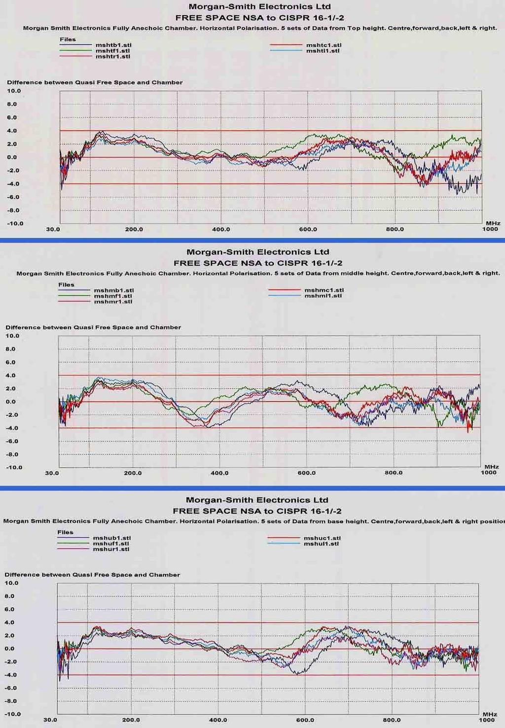
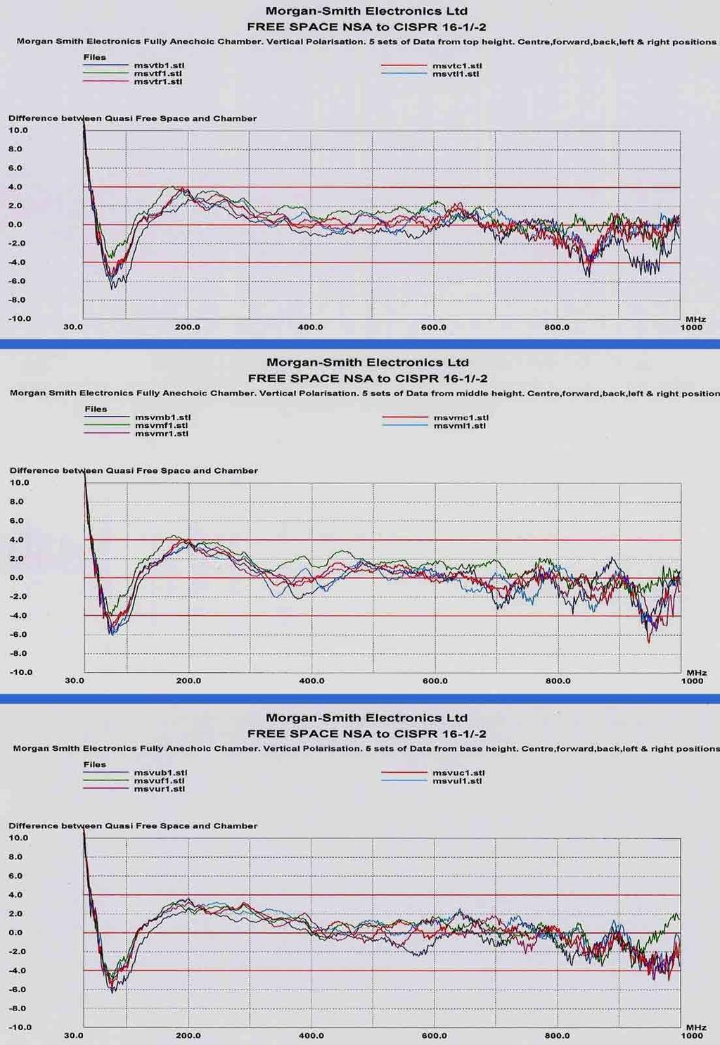
2 Page 2 of 3 Modus Operandi The EN document provides the architecture for a method which is derived from work done at the National physical laboratories in the UK & elsewhere in Europe. Essentially a F.A.R (Fully Anechoic Room) should emulate a free space environment with an antenna measuring point set at 3 metres to the front face of the EUT cylinder. The EUT set-up at Morgan-Smith s can be said to occupy a volume in the form of a cylinder of 0.7m diameter & 0.7m high placed 0.8 metres above the chamber floor. The size of the cylinder has to emulate typical EUT set-ups with their associated cabling whilst matching the performance of the chamber. To test the performance of the chamber in question, a small bicon antenna is used to transmit a signal from five points on the periphery of the flat plane of the cylinder and at three heights, namely the centre of the cylinder, the top & base. On any flat plane in the cylinder we are transmitting from the centre, forward, back, left & right positions as seen from the receive antenna. With both antennas calibrated (as a pair) in the free field for 3.0 metres and the AF s taken into the calculation, a comparison on a swept basis between the swept signal with cables connected together and the radiated signal will display the performance of the chamber relative to quasi free-space by showing any unwanted reflections from the chamber surfaces. So for each polarisation there will be fifteen sets of data, thirty in all with both H & V. The calculated data is presented on a linear grid with ± 4dBs limit lines shown. The graphs are grouped together with the five transmission points from each plane appearing on one grid. The swept range was made in a single sweep 30MHz MHz. The Test Equipment The measurement is essentially differential. The heart of the measurement is the R&S ESPI-3 spectrum analyser with a tracking generator output operating between 30MHz & 1GHz. The tracking generator feeds into the miniature transmitting bicon (UBAA-9115) via a 10dB pad. The received input to the analyser comes from the Schwarzbeck (VULB 9163) Bilog antenna. Height positioning of the receive antenna is critical & in this case was set at 1.2Metre, mid point between floor & ceiling. Where possible, return cabling from both antennas should be kept at balun height for 2 metres before falling to the floor. The antennas used are listed below, all of which hold an independent UKAS calibration certificate applicable to the task of measuring the FSNSA. The whole measuring system is software controlled using EMCH s NSTL/NSIL software program. Equipment Standards Verification The Rohde & Schwarz ESPI-3 Analyser. Ser. No UKAS Cert /10/03 The VULB Bilog Ant. Ser. No UKAS calibrated jointly with the UBAA 9115 below. The Schwarzbeck UBAA 9115 Ser. No.104, UKAS calibrated 28/8/03 Cert. No.2506 Two Weinschel 10dB microwave attenuators. (VSWR elimination, attached to antennas). Portable Computer AJP-D800P with EMCH s NSTL/NSIL software package. Set of Rosenberger microwave quality coaxial cabling plus special RF antenna stands supplied by EMCH. Data The data is presented graphically with all the five results from each level of the cylinder shape printed on a single grid. The horizontal axis displays the frequency linearly, whilst the vertical axis extends to plus and minus 10dBs about a centre zero line. The tolerance limits of ± 4dBs are shown in red.
3 Results Page 3 of 3 It was anticipated that there would be some deviations from the ± 4dBs especially between 30MHz and 250MHz of the swept spectrum in vertical polarisation. This will be due to rather low ceiling height. In most cases with vertical polarisation the bow-tie elements of the receive antenna tend to couple to the surfaces of the chamber. Hence, there is a recognised problem in the correct antenna factor being applied between 30MHz and about 250MHz even though the antennas were correctly calibrated in quasi free-space. For a more in-depth assessment of the performance may I suggest you refer to the contents of the Technical report SMT4-CT issued by M. Alexander of NPL in May The data supplied during this test could conceivably be used to make some corrections or allowances to the EUT test data and present results closer to the real values. From 250MHz upward the return data predominantly remains good & reasonably within the ± 4dBs. However, some excursions were also apparent between 800MHz and 1000MHz on both polarisations. This will be due to the lack of any hybrid absorber being fitted which starts to come into effect from the 800MHz region upwards. Summary Provided the test range is maintained in the diagonal configuration as measured during the NSTL test then return data will emulate the uncertainties shown on the graphs. If emissions from the EUT can be verified as to their polarisation then particular graph structures could be used to correct the received data and thus provide a more accurate assessment of the EUT performance. In any event most troublesome emissions occur from 300MHz upward & in which case straight data can be taken with margins displayed on the graph print-outs. To cut down the possibility of failure at a Test House after undergoing in-house testing it might be worth considering in the future the cost of covering some surfaces with hybrid cones. Engineer witnessing test Engineer carrying out test : Mr. Peter Morgan Smith (M-S Electronics Ltd.) : John Wombwell (EMCH) Report compiled by : John Wombwell SIGNED: Enclosed There are six graphs (grouped as three horizontal & three Vertical) with five sets of data (from each level) on each graph grid. The file naming procedure has already been explained. The 30MHz 1000MHz is shown in an expanded linear form, which will prove helpful in using as a correction. END OF REPORT
4
5
6 EMC HIRE Ltd Ivel Road Shefford Bedfordshire. SG17 5JU Tel: Fax: OUR REF : 119T/04 YOUR REF : 04PO181 DATE OF TEST : 4 th Sept,04 REPORT DATE : 6 th Sept, 04 Morgan-Smith Electronics Ltd., Page 1 of 3 126, Great North Road, Hatfield, Herts,. AL9 5JN att: Mr. Peter Morgan-Smith TEST REPORT Subject Field Uniformity EN (1997) in a F.A.R at Morgan-Smith Electronics Ltd., Hatfield The Contract A contract was raised by Morgan-Smith Electronics Ltd. to perform a Field Uniformity test as per EN (1997), in the Fully-Anechoic Chamber (F.A.R.) belonging to the EMC facility at Morgan- Smith s in Hatfield. This is a standard test to verify that a chamber can meet the requirements of EN , by looking at the possible variations of an immunity field across the area of a flat plane 1.5 metre across by 1.5 metres high (centred on the EUT position), over a 3 metre range, when transmitted with a fixed height antenna. The test is made in both horizontal & vertical polarisations. The Test Site The Test Site was the FAR (Fully-anechoic Room) at Morgan-Smith Electronics Ltd. measuring 6 metres long by 4.8 metres wide, with a height of 2.4 metres. All six inner surfaces of the room are totally covered with ferrite tiles. A single access door was provided adjacent to the EUT end. Coaxial transmission I/O adaptors were provided just at mid floor level two metres from the door. All normally exposed metal reflecting surfaces had been diligently boxed in with ferrite tiling custom clad to boxed surfaces. The receive antenna site was positioned roughly diagonally across the chamber facing the turntable in the opposite corner but equally distanced from the corners to facilitate a 3 metre range between it and the turntable. The plane grid for the sixteen probe positions was set up directly over the normal EUT position, but measured 1.0m across by 0.8m high. The grid started at 0.8metres above floor level. All 16 positions were located by hand on a telescopic mount designed for the purpose. A reduced 16 point square grid was chosen to match the architecture of the chamber and in response to the NSTL figures produced the previous day.
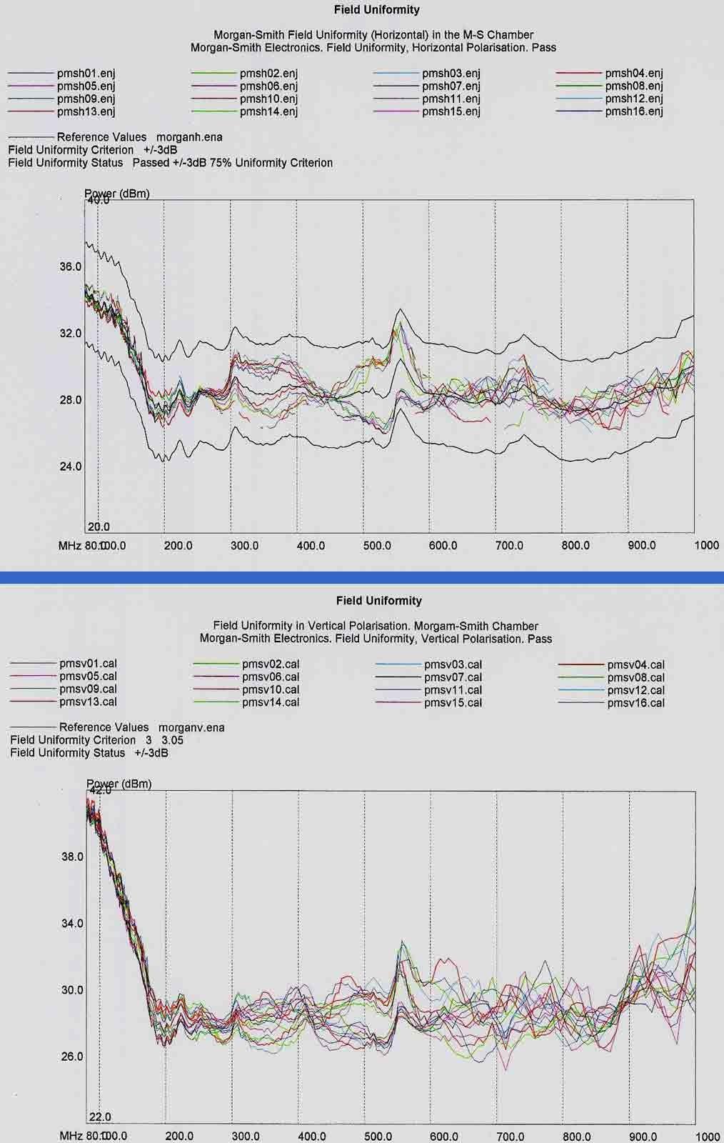
7 Modus Operandi Page 2 of 3 The criteria for reaching the required standard in Field Uniformity is laid down in EN (1997). A frontal plane area in the form of a square measuring 1.5m by 1.5m and standing 0.8metres above the floor is divided into 16 symmetrical points every 0.5 metres. However, in this particular case due to the size of the chamber it was decided to look at the F.U. on a 1.0m x 0.8m grid. The transmit antenna was positioned diagonally along the main length of the chamber. The Field Probe was adjusted for 3 metres between itself and the phase centre of the 6141A X Wing Bilog antenna. This particular model Bilog would be less susceptible to floor/ceiling coupling A standard immunity swept frequency calibration is carried out under computer control from 80MHz to 1GHz at a logarithmic step change of 1% for each of the sixteen positions. A field strength tolerance of Volts/metre was set up with the forward power being monitored at each frequency and all data being stored on computer. At the conclusion of all sixteen swept positions a computer programme algorithm determines, using the forward power in dbm, how many frequency points from each position collectively fall within ±3dB or 0 +6dB of each other. Up to 25% of all data points, if falling outside the tolerance, can be discarded. The uniformity criterion can then be considered met if the remaining 75% lie within. There is however a further relaxation allowing 3% of the remaining data points to be up to 10dB out. This entire operation is carried out for both horizontal & vertical polarisations. The Test Equipment The measurement is essentially relative. The pertinent parts of the measurement are a Telescopic Probe Mount which is RF transparent & can position the field probe in each of the sixteen points of the grid. A UKAS or NPL calibrated field probe to measure the field in the appropriate plane. An RF power meter to monitor the forward power to the antenna via a directional coupling unit. The power meter, RF probe & signal generator are all on the GPIB. The transmit antenna was the Chase 6141A X wing Bilog. The whole measuring system is software controlled using EMCH s standard immunity package conforming to the EN (1997) verification programme. AR.30W1000 RF power amplifier. 30 Watts. 20MHz-1GHz Supplied by EMCH. Computer with EMCH s Immunity and software package. The Manual Telescopic probe positioner. SI-200 and FP3000 field probe & controller. (EMCH) FP-3000A field probe. Ser. N Cal d 11/2/04 by NPL ref: E Chase 6141A X wing bilog antenna. Calibration not applicable in this test. Boonton 9200B Power meter. UKAS cal d 30/6/2003 Cert:003137/01/010 Rohde & Schwarz SML-01 sig gen. UKAS cal d 17/3/04 Cert:04873 Data The data is presented in two parts, one being for horizontal polarisation with 16 files beginning PMSH cal the other in vertical beginning PMSV cal. Within each polarisation there is a log file, a report file, an error file and the sixteen data field uniformity graph. Calibration Log File The file comprises a header with relevant information derived from the sixteen positioned files from which the software has determined the 25% rejected at each of the frequency points measured. These frequency points will run from 80MHz to 1GHz at 1% interval and display against each frequency the level in dbm and the file/position rejected. Note the last two characters of the rejected file name indicate the actual physical position of the probe within the square plane grid. The Errors File The file comprises a header with relevant information derived from Cal Log and shows those frequency points which lie outside the ±3dB limit. In detail, against a particular frequency, we subtract the average power from the max power to give a result (B-A), we then do the same again with the minimum power (C-A) and if (B-A ) is more than +3dB or (C-A) is less 3dB then we have an error or rejection.
8 Page 3 of 3 The report File Again the file comprises a header with relevant information derived from the sixteen positioned files along with the maximum power from the remaining points which produce on the graph entitled Field Uniformity the two reference lines of (in this case 3dB & +3dBs) with the chosen files embraced. The Field Uniformity Graph A Pass means that all the final selected data ( excluding 3% which is allowed ±10dB) lies within a ±3dB criterion. On the failure side there are two conditions: The first being that a number of data points (exceeding the 25%) lay outside the ±3dB limit. However, the standards allow a Pass on condition that the remaining points outside the limit are no more than ±10dB for 3% or less of the remaining frequency points. A total failure is indicated when there are more than 25% of the frequency points outside ±3dB or any additional points greater than ±10dB. Our method in displaying the graph in the format shown has two advantages, one being that the End User can see how hard the amplifier is being worked over a specific range of frequencies, and the other showing the absence of the rejected points by gaps in the trace. Results A combination of the reduced grid size has permitted a pass in both Horizontal & Vertical polarisation. This particular test has been performed primarily to check the Chamber performance although the calibration files were downloaded onto the Morgan-Smith Electronics Immunity software program for future evaluation and use. Summary As Morgan-Smith Electronics Ltd. is testing devices which lie safely in size within the 1m x 0.8m grid, then a fairly high degree of field strength uniformity can be expected thus providing the necessary confidence in product evaluation. It would be stressed of course that reliable data also depends upon Morgan-Smiths calibration data concerning their own voltage field probes and power meters. Engineer witnessing test Engineer carrying out test : Mr. Peter Morgan Smith (Morgan-Smith Electronics Ltd) : John Wombwell (EMCH) Report compiled by : John Wombwell SIGNED: Attached Two complete packs of data printouts. One for vertical & one for horizontal. These include a Calibration Log File, a Calibration Report File & the Errors file (if appropriate) plus a graphical presentation of the selected files. The titles are given for each group & the figures are self explanatory. END OF REPORT
9
Measurement of RF Emissions from a Caterpillar Inc. MSS3s RF ID Key Fob
 Measurement of RF Emissions from a Caterpillar Inc. MSS3s RF ID Key Fob For Caterpillar Inc. 330 S.W. Adams Street Peoria, IL 61630 P.O. Number JBL 11260 Date Tested May 11, 2016 Test Personnel Mark Longinotti
Spurious Emissions & Emission Mark Report
 Spurious Emissions & Emission Mark Report for the SRT Marine Technology Ltd Neon 403-0001 AIS Class B Transceiver No. Issue#1: 20 th July 2009 EU Notified Body FCC & VCCI Registered BSMI Lab ID: SL2-IN-E-3008
Fully Anechoic Room Validation Measurements to CENELEC pren
 Fully Anechoic Room Validation Measurements to CENELEC pren517-3 M.A.K.Wiles*,W.Muellner** *ETS,Rochester,UK **Austrian Research Center,Seibersdorf,Austria Abstract Many small to medium sized EMC anechoic
Normalized Site Attenuation Test Report
 NVLAP LAB CODE 200974-0 Normalized Site Attenuation Test Report Test Specification NORMALIZED SITE ATTENUATION (NSA) Range 30 MHz 1GHz using the methods of ANSI C63.4-2009; EN 50147-2 (1997); CISPR 16-1-4
EMC TEST REPORT for LEDELS LIGHTING CO., LTD. LED module Model No. : LL-F12T4815X6B
 Page 1 of 27 Report No. R011412016E-1 EMC TEST REPORT for LEDELS LIGHTING CO., LTD LED module Model No. : LL-F12T4815X6B Prepared for : LEDELS LIGHTING CO., LTD Address : 5F, Block C, Mingjinhai Ind. Park,
Test sites for EMC measurements
 Test sites for EMC measurements EMV Fachtagung 21. Januar 2014 Christophe Perrenoud www.montenaemc.ch montena emc Route de Montena 75 CH - 1728 Rossens Tel. +41 26 411 93 33 Fax +41 26 411 93 30 office.emc@montenaemc.ch
EMC TEST REPORT. Report No.: TS EME Model No.: 33XR-A Issued Date: Jan. 08, 2009
 Page 1 of 18 EMC TEST REPORT Report No.: TS08100063-EME Model No.: 33XR-A Issued Date: Jan. 08, 2009 Applicant: Test Method/ Standard: Test By: FLUKE CORP. 6920 Seaway Blvd, M/S 266D Everett, WA 98203
TEST REPORT. PolyComp 32X80P7.621YHB Electronic Sign. tested to the. 47 Code of Federal Regulations. Part 15 - Radio Frequency Devices
 EMC Technologies (NZ) Ltd PO Box 68-307 Newton, Auckland Phone 09 360 0862 Fax 09 360 0861 E-Mail Address: aucklab@ihug.co.nz Web Site: www.emctech.com.au TEST REPORT PolyComp 32X80P7.621YHB Electronic
How will the third edition of IEC affect your test facility?
 How will the third edition of IEC 61000-4-3 affect your test facility? Changes in the standard could mean that your amplifier is no longer powerful enough Introduction The third edition of IEC 61000-4-3
TEST REPORT FROM RADIO FREQUENCY INVESTIGATION LTD.
 TEST REPORT FROM RADIO FREQUENCY INVESTIGATION LTD. Test Of: Wood & Douglas Ltd ST500 Transmitter Test Report Serial No: RFI/EMCB2/RP39403B This Test Report supersedes RFI Test Report No.: RFI/EMCB1/RP39403B
EMC ANECHOIC CHAMBERS 5-METER CHAMBERS
 ETS-Lindgren's FACT 5 Chambers offer semi-anechoic radiated emissions (RE) and fully anechoic radiated immunity (RI) compliance test capability for most international EMC compliance regulations. FACT 5
RADIOMETRICS Midwest Corporation
 RADIOMETRICS Midwest Corporation Shielding Effectiveness Test Report Tests Performed on an IMS-AMCO Shielded Rack Test Unit #2 Part Number S40469 Radiometrics Document RP-5760B Test Specifications MIL-STD-285
A GTEM BEST PRACTICE GUIDE APPLYING IEC TO THE USE OF GTEM CELLS
 - 27-39 H1 A BEST PRACTICE GUIDE APPLYING IEC 61-4-2 TO THE USE OF CELLS A. Nothofer, M.J. Alexander, National Physical Laboratory, Teddington, UK, D. Bozec, D. Welsh, L. Dawson, L. McCormack, A.C. Marvin,
Ave output power ANT 1(dBm) Ave output power ANT 2 (dbm)
 Ave output power ANT 2 (dbm)") Page 41 of 103 9.6. Test Result The test was performed with 802.11b Channel Frequency (MHz) power ANT 1(dBm) power ANT 2 (dbm) power ANT 1(mW) power ANT 2 (mw) Limits dbm / W Low 2412 7.20 7.37 5.248 5.458
Page 41 of 103 9.6. Test Result The test was performed with 802.11b Channel Frequency (MHz) power ANT 1(dBm) power ANT 2 (dbm) power ANT 1(mW) power ANT 2 (mw) Limits dbm / W Low 2412 7.20 7.37 5.248 5.458
For. Unit D16/F. should not use it to claim FCC ID: 2AAIN-MNGLOS
 Page 1 of 49 TESTT REPORT For Applicant : ACOUSTMAX INTERNATIONAL CO.., LTD Unit D16/F Cheuk Nang Plaza 250 Hennessy Road Address : WanchaiHongKong Product Name : Monster GLO Model Name : MNGLO-S, MNGLO-L,MNGLO-M,MNGLO-Mini
MANUAL. PCD - Precision Conical Dipole Antenna
 MANUAL PCD - Precision Conical Dipole Antenna RF Engineering MANUAL Precision Conical Dipole Antenna 12.10.2009 Version 2.0 Notice Seibersdorf Labor GmbH reserves the right to make changes to any product
TEST REPORT... 1 CONTENT...
 CONTENT TEST REPORT... 1 CONTENT... 2 1 TEST RESULTS SUMMARY... 3 2 EMC RESULTS CONCLUSION... 4 3 LABORATORY MEASUREMENTS... 6 4 EMI TEST... 7 4.1 CONTINUOUS CONDUCTED DISTURBANCE VOLTAGE TEST... 7 4.2
RADIO TEST REPORT. For MODEL NO FCC ID: C3K1703 IC ID: 3048A Test Report No. R-TR190-FCCIC-UNII-1 Issue Date: 14 September 2015
 RADIO TEST REPORT For MODEL NO. 1703 FCC ID: C3K1703 IC ID: 3048A-1703 Test Report No. R-TR190-FCCIC-UNII-1 Issue Date: 14 September 2015 FCC CFR47 Part 15 Subpart E Industry Canada RSS-247 Issue 1 Prepared
Model BiConiLog Antenna. User Manual
 Model 3149 BiConiLog Antenna User Manual ETS-Lindgren Inc. reserves the right to make changes to any products herein to improve functioning or design. Although the information in this document has been
EN :2007+A1:2011 Electromagnetic compatibility Emission standard for residential, commercial and light-industrial environments
 EMC Page 3 / 33 Test report No.: EN 61000-6-3:2007+A1:2011 Electromagnetic compatibility Emission standard for residential, commercial and light-industrial environments Date of measurement: 2013-10-16
Contents. EH-H21/12 Page 2 of 38
 Contents. Summary.... Date and Place of Measurements.... Description of the Test Site.... Measurements and Results..... Normalised Site Attenuation (NSA)...... Test Description...... Measurement Equipment...
Advanced Compliance Solutions, Inc FAU Blvd, Suite 310 Boca Raton, Florida (561)
") 2129.01 Advanced Compliance Solutions, Inc. 3998 FAU Blvd, Suite 310 Boca Raton, Florida 33431 (561) 961-5585 Technical Report No. 09-2067a-2 EMI Evaluation of the AMM Marketing, LLC s E-Pulse UH 900,
2129.01 Advanced Compliance Solutions, Inc. 3998 FAU Blvd, Suite 310 Boca Raton, Florida 33431 (561) 961-5585 Technical Report No. 09-2067a-2 EMI Evaluation of the AMM Marketing, LLC s E-Pulse UH 900,
EMC TEST REPORT for Repel-it. REPEL-IT ULTRASONIC PEST REPELLER Model No. : REPEL-IT/UPR/AN-B019
 Page 1 of 22 Report No. 201311760E EMC TEST REPORT for Repel-it REPEL-IT ULTRASONIC PEST REPELLER Model No. : REPEL-IT/UPR/AN-B019 Applicant : Repel-it Address 168 Logan Road, Woolloongabba, Brisbane,
EMC TEST REPORT for : DONGGUAN EVER DEVELOPMENT ELECTRONIC CO., Electronic calculator Model No.: KF15758
 Page 1 of 20 Report No. R011604553E EMC TEST REPORT for DONGGUAN EVER DEVELOPMENT ELECTRONIC CO., LTD. Electronic calculator Model No.: KF15758 Prepared for Address Prepared by Address : DONGGUAN EVER
Archived 3/18/10 USER MANUAL EMCO MODEL 3141 BICONILOG TM LOG-PERIODIC / T BOW-TIE ANTENNA Rev A 01/97
 USER MANUAL EMCO MODEL 3141 BICONILOG TM LOG-PERIODIC / T BOW-TIE ANTENNA 399236 Rev A 01/97 GENERAL DESCRIPTION The EMCO Model 3141 is the latest evolution in the popular bow-tie/log periodic combination
EMC TEST REPORT For INNOKIN TECHNOLOGY CO., LIMITED. ITaste vv. Model No.: ITaste vv
 EMC TEST REPORT For INNOKIN TECHNOLOGY CO., LIMITED ITaste vv Model No.: ITaste vv Prepared for : INNOKIN TECHNOLOGY CO., LIMITED Address : 3# Floor, #B Building, Heng Chang Rong Industrial Park, Gonghe
Report for Excelsys EMC Measurements for 6Xgen Purchase Order: by Project Number EMT08J027
 Report for Excelsys on EMC Measurements for 6Xgen Purchase Order: by email Project Number EMT08J027 Tom O Brien, Engineering Director ElectroMagnetic Technologies Ltd, Cork, June 2007 Executive Summary
Model 3140B BiConiLog Antenna User Manual
 Model 3140B BiConiLog Antenna User Manual Model 3140B mounted onto a 7-TR tripod (not included) ETS-Lindgren L.P. reserves the right to make changes to any product described herein in order to improve
Revision history. Revision Date of issue Test report No. Description KES-RF-14T0042 Initial
 Page (2 ) of (34) Revision history Revision Date of issue Test report No. Description - 2014.08.25 Initial Page (3 ) of (34) TABLE OF CONTENTS 1. General information... 4 1.1. EUT description... 4 1.2.
Accredited Standards Committee C63 - EMC
 Draft C63.-5-201x Annex N Site-Specific Qualification Procedure for Hybrid Antennas (intended to be used for the making of ANSI C63.4-201x Final Compliance Measurements) Harry H. Hodes, NCE Principal EMC
TABLE OF CONTENTS. 6. PHOTOGRAPH Photo of Conducted Emission Measurement Photo of Radiation Emission Measurement...
 TABLE OF CONTENTS 1. SUMMARY OF TEST RESULTS... 4 2. GENERAL INFORMATION... 5 2.1 Details of E.U.T.... 5 2.2 Description of Support Device... 5 2.3 Block Diagram of Test Setup... 5 2.4 Test Facility...
Semi Anechoic Chamber (SAC)
") 1 of 9 Semi Anechoic Chamber (SAC) Approximate Dimensions of 3m Semi Anechoic Chamber (SAC) Length: 10m Width: 9m Height: 9m Frequency range of Semi Anechoic Chamber: 9 KHz to 40 GHz Emission test (EMI):
1 of 9 Semi Anechoic Chamber (SAC) Approximate Dimensions of 3m Semi Anechoic Chamber (SAC) Length: 10m Width: 9m Height: 9m Frequency range of Semi Anechoic Chamber: 9 KHz to 40 GHz Emission test (EMI):
Verification of Conformity On Behalf of
 Verification of Conformity On Behalf of EVERPRO TECHNOLOGIES COMPANY LTD. HDMI Active optical Cable Model No.: HDMI OPTICAL FIBER CABLE 330FT, 300FT, 250FT, 200FT, 150FT, 100FT, 50FT Prepared for : EVERPRO
1 Introduction Test Specification Environment Relevant standards Emissions Immunity...
 CONTENTS 1 Introduction... 4 2 Test Specification... 6 2.1 Environment... 6 2.2 Relevant standards... 6 2.2.1 Emissions... 6 2.2.2 Immunity... 7 3 Test Results... 8 3.1 Conducted emissions (9kHz to 30MHz)...
FCC Verification TEST REPORT
 FCC Verification TEST REPORT Product: 5 in 1 Environment Meter Model no.: ET-965 Trade Mark: N/A Report No.: TCT140915E005 Issued Date: Sep. 22, 2014 Issued for: Shenzhen Flus Technology Co., Ltd 3rd Floor,
Laird Attn: Bill Steinike W66 N220 Commerce Ct. Cedarburg, WI Report Constructed by: Zach Wilson, EMC Technician Signature: Date: June 21, 2017
 A Test Report # 317241 Equipment Under Test: RM024 Test Date(s): June 9 and June 21, 2017 Prepared for: Laird Attn: Bill Steinike W66 N220 Commerce Ct. Cedarburg, WI 53012 Report Issued by: Adam Alger,
APPLICATION FOR VERIFICATION On Behalf of Carewell Electric Technology (Zhongshan) Co., Ltd. REMOTE CONTROL Model No.: AC8 FCC ID: 2AAZPAC8
 Co., Ltd. REMOTE CONTROL Model No.: AC8 FCC ID: 2AAZPAC8") Page 1 of 19 APPLICATION FOR VERIFICATION On Behalf of Carewell Electric Technology (Zhongshan) Co., Ltd. REMOTE CONTROL Model No.: AC8 Prepared for : Carewell Electric Technology (Zhongshan) Co., Ltd.
Page 1 of 19 APPLICATION FOR VERIFICATION On Behalf of Carewell Electric Technology (Zhongshan) Co., Ltd. REMOTE CONTROL Model No.: AC8 Prepared for : Carewell Electric Technology (Zhongshan) Co., Ltd.
Verification On Behalf of Shenzhen Leer Chuang Technology Co., Ltd.
 Page 1 of 13 Report No. R011603851E Verification On Behalf of Shenzhen Leer Chuang Technology Co., Ltd. Digital Scale Model No.: SH-370, SH-368, SH-366, SH-367, SH-369, SH-233, SH-228, SH-258, SH-235,
Electromagnetic field distribution within a semi anechoic chamber
 Electromagnetic field distribution within a semi anechoic chamber Martin Pospisilik and Josef Soldan Abstract The paper deals with determination of a resonant frequency of a semi anechoic chamber with
FCC Part 15B Measurement and Test Report. For. GlobTek, Inc. 186 Veterans Dr. Northvale, NJ USA. FCC Part 15 Subpart B.
 Test Standards: FCC Part 15B Measurement and Test Report Product Description: Tested Model: Report No.: For GlobTek, Inc. 186 Veterans Dr. Northvale, NJ 07647 USA FCC Part 15 Subpart B Power Supply GT-93020-0324
Measurement of RF Interference from a Canopy 900MHz Access Point and Subscriber Module Using A Yagi Antenna
 Measurement of RF Interference from a Canopy 900MHz Access Point and Subscriber Module Using A Yagi Antenna For : Motorola, Inc. 1301 East Algonquin Road Schaumburg, IL 60196 P.O. No. : 40335 Date Tested
Title: Test on 5.8 GHz Band Outdoor WiFi (802.11b/g) Wireless Base Station
 Wireless Base Station") Page 20 of 51 Pages 7.5. Conducted spurious emission 7.5.1. Requirements: Clause 15.247(d). In any 100 khz bandwidth outside the frequency band in which the spread spectrum or digitally modulated intentional
Page 20 of 51 Pages 7.5. Conducted spurious emission 7.5.1. Requirements: Clause 15.247(d). In any 100 khz bandwidth outside the frequency band in which the spread spectrum or digitally modulated intentional
FCC Test Report. Report No.: AGC FE02 CLIENT : INNOVATIVE CONCEPTS AND DESIGN LLC. Attestation of Global Compliance (Shenzhen) Co., Ltd.
 Co., Ltd.") Page 1 of 43 FCC Test Report Report No.: AGC03588150607FE02 FCC ID : 2AE6GUHF 6000HHM APPLICATION PURPOSE : ORIGINAL EQUIPMENT PRODUCT DESIGNATION : Wireless Microphone BRAND NAME : Gemini MODEL NAME :
Page 1 of 43 FCC Test Report Report No.: AGC03588150607FE02 FCC ID : 2AE6GUHF 6000HHM APPLICATION PURPOSE : ORIGINAL EQUIPMENT PRODUCT DESIGNATION : Wireless Microphone BRAND NAME : Gemini MODEL NAME :
TEST REPORT. For RFID READER/WRITER. In conformity with. FCC CFR 47 Part15 Subpart C
 TEST REPORT For RFID READER/WRITER In conformity with FCC CFR 47 Part15 Subpart C Model: TR3XM-SD01 / TR3XM-SU01 / TR3XM-SN01 FCC ID: MK4TR3XM-SX01 Test Item: RFID READER/WRITER Report No: RY1203Z12R1
F C C - TESTREPORT REPORT NO.: FCC-02/
 F C C - TESTREPORT REPORT NO.: FCC-02/09-0010 pkm Ohmstrasse 1 D-84160 Frontenhausen Tel : 08732-6381 Fax : 08732-2345 e-mail: pkm.accredited-labs@t-online.de Seite/page: 2 of 12 TABLE OF CONTENTS Page
Dongguan Nore Testing Center Co., Ltd. Report No.: NTC F TABLE OF CONTENTS
 TABLE OF CONTENTS 1. SUMMARY OF TEST RESULTS... 4 2. GENERAL INFORMATION... 5 2.1 Details of E.U.T.... 5 2.2 Description of Support Device... 5 2.3 Block Diagram of Test Setup... 5 2.4 Test Facility...
TEST REPORT. Power Spout PLT V. tested to the specification. EN : Amendment 1: Electromagnetic compatibility (EMC)
") EMC Technologies (NZ) Ltd PO Box 68-307, Newton Auckland 1145 New Zealand Phone 09 360 0862 Fax 09 360 0861 E-Mail Address: aucklab@ihug.co.nz Web Site: www.emctech.com.au TEST REPORT Power Spout PLT 100
EMC Technologies (NZ) Ltd PO Box 68-307, Newton Auckland 1145 New Zealand Phone 09 360 0862 Fax 09 360 0861 E-Mail Address: aucklab@ihug.co.nz Web Site: www.emctech.com.au TEST REPORT Power Spout PLT 100
Compliance Engineering Ireland Ltd
 Page 1 of 27 Compliance Engineering Ireland Ltd RAYSTOWN, RATOATH ROAD, ASHBOURNE, CO. MEATH, IRELAND Tel: +353 1 8256722 Fax: +353 1 8256733 Project Number: 10E2475-5 Prepared for: Biancamed Ltd By Compliance
Version TEST REPORT NO. DATE DESCRIPTION
 Version NO. DATE DESCRIPTION HCTR1302FR13 February 14, 2013 - First Approval Report - Additional Model Name Page 2 of 25 Table of Contents 1. GENERAL INFORMATION... 4 2. EUT DESCRIPTION... 4 3. TEST METHODOLOGY...
FCC CFR47 PART 15 SUBPART C INDUSTRY CANADA RSS-GEN AND RSS-210 CERTIFICATION TEST REPORT FOR BROADCOM BLUETOOTH MODULE MODEL NUMBER: BCM92046MD
 FCC CFR47 PART 15 SUBPART C INDUSTRY CANADA RSS-GEN AND RSS-210 CERTIFICATION TEST REPORT FOR BROADCOM BLUETOOTH MODULE MODEL NUMBER: BCM92046MD IC #: 4324A-BRCM1029 REPORT NUMBER: 07U11199-1C ISSUE DATE:
FCC TEST REPORT On Behalf of. Global Tech China Limited. Solar Light(Large)/28W,16W. Model No.: Additional Model No: Please Refer To Page 15
/28W,16W. Model No.: Additional Model No: Please Refer To Page 15") FCC TEST REPORT On Behalf of Global Tech China Limited Solar Light(Large)/28W,16W Model No.: 00013022 Additional Model No: Please Refer To Page 15 Prepared for : Global Tech China Limited Address : 3 Flat
FCC TEST REPORT On Behalf of Global Tech China Limited Solar Light(Large)/28W,16W Model No.: 00013022 Additional Model No: Please Refer To Page 15 Prepared for : Global Tech China Limited Address : 3 Flat
RF Test Report. Report No.: AGC EE13. CLIENT : Zhengzhou Eshow Import and Export Trade Co.,Ltd.
 Page 1 of 80 RF Test Report Report No.: AGC08074160901EE13 PRODUCT DESIGNATION : Two way radio BRAND NAME : Retevis MODEL NAME : RT1 CLIENT : Zhengzhou Eshow Import and Export Trade Co.,Ltd. DATE OF ISSUE
EMC TEST REPORT. For. Boardcon Technology Limited. MINI9G45 Computer on Module. Model No. : MINI9G45
 REPORT NO. PRSZ15110502E EMC TEST REPORT For Boardcon Technology Limited. MINI9G45 Computer on Module Model No. : MINI9G45 Prepared For : Boardcon Technology Limited. : Room 702, Hua Feng Xin An Business
King Pigeon Communication Co., Limited
 APPLICATION FOR ELECTROMAGNETIC COMPATIBILITY DIRECTIVE On Behalf of King Pigeon Communication Co., Limited Remote Controller RTU Model No.: S130, S140, S150, S180, S25x, S26x, S27x, RTU501x, RTU502x,
FCC TEST REPORT. For. SPECTRA Technologies Holdings Co. Ltd EFTPOS. Model No. : SPECTRA T1000
 FCC ID: VWZT1000-1 - FCC TEST REPORT For SPECTRA Technologies Holdings Co. Ltd EFTPOS Model No. : SPECTRA T1000 Prepared for : SPECTRA Technologies Holdings Co. Ltd Address Unit1301-1309,19-20,Tower11,Grand
Electrical FOR:
 839.01 Electrical Hermon Laboratories Ltd. Harakevet Industrial Zone, Binyamina 30500, Israel Tel. +972-4-6288001 Fax. +972-4-6288277 E-mail: mail@hermonlabs.com TEST REPORT ACCORDING TO: EN 300 113-2
7. Transmitter Radiated Spurious Emissions and Conducted Spurious Emission
 7. Transmitter Radiated Spurious Emissions and Conducted Spurious Emission 7.1 Test Setup Refer to the APPENDIX I. 7.2 Limit According to 15.247(d), in any 100 khz bandwidth outside the frequency band
Advanced Test Equipment Rentals ATEC (2832) CNE III Comparison Noise Emitter
 CNE III Comparison Noise Emitter") Established 1981 Advanced Test Equipment Rentals www.atecorp.com 800-404-ATEC (2832) CNE III Comparison Noise Emitter Product Technical Information CNE III Comparison Noise Emitter The industry standard
Established 1981 Advanced Test Equipment Rentals www.atecorp.com 800-404-ATEC (2832) CNE III Comparison Noise Emitter Product Technical Information CNE III Comparison Noise Emitter The industry standard
CENTRE OF TESTING SERVICE INTERNATIONAL
 CENTRE OF TESTING SERVICE INTERNATIONAL OPERATE ACCORDING TO ISO/IEC 17025 FCC TEST REPORT TEST REPORT NUMBER : CGZ3150202-00097-E A101,No.65,Zhuji Highway,Tianhe District,Guangzhou, Guangdong, China Report
E MC Ane c hoi c Chambers
 E MC Ane c hoi c Chambers.)+6! Features 6 MHz - 8 GHz Frequency Range Full Compliance Testing for Radiated Emissions: - ANSI C6. Parts 5 & 8 - EN 57 - CISPR / EN55 - CISPR 6/ EN556 - CISPR / EN55 - VCCI
EN / EN RADIO TEST REPORT. Shanghai Anviz Technology Co.Ltd Fingerprint & RFID Time Attendance Model No.: A300
 Page 1 of 28 Report No.: T1861387 02 EN 300 330-1/ EN 300 330-2 RADIO TEST REPORT On Behalf of Shanghai Anviz Technology Co.Ltd Fingerprint & RFID Time Attendance Model No.: A300 Prepared for : Shanghai
TEST REPORT : 2AIB7MGS. TEST DATE : to
 TEST REPORT APPLICANT : Hohem Technology Co.,Ltd PRODUCT NAME : 3-Axis Stabilizing Gimbal for Smartphone MODEL NAME BRAND NAME FCC ID STANDARD(S) : isteady Mobile : Hohem : 2AIB7MGS : 47 CFR Part 15 Subpart
Report for Excelsys EMC Measurements for 4Xgen Purchase Order: Project Number EMT07J026 Rev. B
 Report for Excelsys on EMC Measurements for 4Xgen Purchase Order: Project Number EMT07J026 Rev. B Rev Date Comment A April 2007 Change in DoC content B May 2007 Added Immunity Section EMT is a TÜV Appointed
TRANSMITTER MODEL: KAS-2030M
 Page 1 of 16 FCC PART 15, SUBPART B and C TEST REPORT for TRANSMITTER MODEL: KAS-2030M Prepared for WILDLIFE TECHNOLOGIES 115 WOLCOTT STREET MANCHESTER, NEW HAMPSHIRE 03103 Prepared by: KYLE FUJIMOTO Approved
EMC TEST REPORT. For MICRO-STAR INT'L CO.,LTD. USB Card Reader
 EMC TEST REPORT For MICRO-STAR INT'L CO.,LTD USB Card Reader Model : StarReader Prepared For : MICRO-STAR INT'L CO.,LTD No.69, Lide St., Jhonghe City, Taipei County 235, Taiwan Prepared By : Shenzhen Best
FCC & IC Certification. Test Report. FCC & Industry Canada Certification. Test Report. for Hetronic USA FCC ID: LW9-CS434TXN IC ID: 2219A-CS434TXN
 FCC & IC Certification Test Report FCC & Industry Canada Certification Test Report for Hetronic USA March 3, 2005 Prepared for: Hetronic USA 4300 Highline Blvd Building 4 Oklahoma City, OK 73108 Prepared
APPLICATION FOR CERTIFICATION On Behalf of Futaba Corporation Radio Control Model No.:T10CG-2.4G FCC ID:AZPT10CG-24G Brand : Futaba
 FCC ID. AZPT10CG-24G Page 1 of 56 APPLICATION FOR CERTIFICATION On Behalf of Futaba Corporation Radio Control Model No.:T10CG-2.4G FCC ID:AZPT10CG-24G Brand : Futaba Prepared for : Futaba Corporation 1080
Electromagnetic Compatibility Test Report FCC test results of an automatic dog brush, model EUT: Type 1 AC/DC adaptor: SYS W2E
 Electromagnetic Compatibility Test Report FCC test results of an automatic dog brush, model EUT: Type 1 AC/DC adaptor: SYS1308-1809-W2E Customer Customer's representative In the capacity of Reference number
FCC Part 22H & 24E Measurement and Test Report
 FCC Part 22H & 24E Measurement and Test Report For Shenzhen Concox Information Technology Co., Ltd Floor 4th, Building B, Gaoxinqi Industrial Park, Liuxian 1st Road, District 67, Bao an, Shenzhen, China
Client Archive No.: - / - 1 Summary: Table of results: shielding effectiveness measurement: References:...
 Contents: 1 Summary:...3 1.1 Table of results:...3 1.1.1 shielding effectiveness measurement:...3 2 References:...3 2.1 Specifications:...3 2.2 Glossary of Terms:...4 2.3 Bibliographical Data:...4 3 General
SHENZHEN LCS COMPLIANCE TESTING LABORATORY LTD. FCC ID: 2ADPC-G6 Report No.: LCS E
 2) Sequence of testing 30 to 1 GHz Setup: --- The equipment was set up to simulate a typical usage like described in the user manual or described by manufacturer. --- If the EUT is a tabletop system, a
For. Tzone FCC ID: FCC Part Description: Product TZ-BT04. Report to Tested By: Manager STR I
 FCCC Part 15C Measurement and Test For Report Tzone Digitall Technology Co.., LTD 16D, Haiying Building, South of Caitian Road, Futiann District, Shenzhen China FCC ID: 2AKSQTZBT04 FCC Rule(s): Product
US Council of EMC Laboratories [USCEL] Technical Issues having Significant Cost Implications for EMC Laboratory Owners/Operators
![US Council of EMC Laboratories [USCEL] Technical Issues having Significant Cost Implications for EMC Laboratory Owners/Operators](/thumbs/74/70107860.jpg "US Council of EMC Laboratories [USCEL] Technical Issues having Significant Cost Implications for EMC Laboratory Owners/Operators") US Council of EMC Laboratories [USCEL] Technical Issues having Significant Cost Implications for EMC Laboratory Owners/Operators Presented to the ACIL CAS EMC Committee On 17 August 2009 [Note: includes
US Council of EMC Laboratories [USCEL] Technical Issues having Significant Cost Implications for EMC Laboratory Owners/Operators Presented to the ACIL CAS EMC Committee On 17 August 2009 [Note: includes
416 Maetan 3-Dong, Yeongtong-Gu, Suwon-Si, Gyeonggi-Do, Korea,
 EMC TEST REPORT According to FCC CFR47 Part 18 Subpart C JOB Number : LBE20110882 1. This test report does not constitute an endorsement by NIST/NVLAP or U.S Government. 2. This test report is to certify
RADIO TEST REPORT SHANGHAI EUCHIPS INDUSTRIAL CO.,LTD. Prepared By : SHANGHAI EUCHIPS INDUSTRIAL CO.,LTD
 SHANGHAI EUCHIPS INDUSTRIAL CO.,LTD RADIO TEST REPORT Prepared For : SHANGHAI EUCHIPS INDUSTRIAL CO.,LTD 3rd and 4th Floor,6th Building No.888,Shuangbai Road, Minhang District,Shanghai,China Product Name:
SHURE ELECTROMAGNETIC COMPATIBILITY LABORATORY TEST REPORT
 SHURE ELECTROMAGNETIC COMPATIBILITY LABORATORY TEST REPORT TEST REPORT TITLE: Electromagnetic Compatibility Tests of the Shure QLXD2-V50 Handheld Transmitter TEST ITEM DESCRIPTION: QLXD2-V50 is a digital
TEST REPORT SZEM CR
 No. 1 Workshop, M-10, Middle section, Science & Technology Park, Shenzhen, Guangdong, China 518057 Telephone: +86 (0) 755 2601 2053 Fax: +86 (0) 755 2671 0594 Email: ee.shenzhen@sgs.com Application No.:
CHARACTERISATION OF IN -HOUSE EMC TESTING FACILITIES FOR PRODUCT DESIGNERS. Paul Kay* and Andrew Nafalski**
 CHARACTERISATION OF IN -HOUSE EMC TESTING FACILITIES FOR PRODUCT DESIGNERS Paul Kay* and Andrew Nafalski** *Austest Laboratories, Adelaide **University of South Australia School of Electrical and Information
Shenzhen Toby Technology Co., Ltd. EMC Test Report. Report No.: TB-EMC Page: 1 of 20
 Shenzhen Toby Technology Co., Ltd. Report No.: TB-EMC125641 Page: 1 of 20 EMC Test Report Application No. : TB12114299 Applicant : Newmb Technology Co., Ltd. Equipment Under Test (EUT) EUT Name : USB HUB
Immunity Test System RIS 3000 / RIS 6000 acc. to IEC/EN
 Description The setup of a radiated immunity test system can be done in the conventional way with many separate instruments or in a more comfortable and less risky way with our new EMC control unit, type
FCC 47 CFR PART 15 SUBPART B TEST REPORT SHENZHEN EAGLE TECHNOLOGY CO., LTD Mirror photo booth Model No.: EAGMR
 FCC 47 CFR PART 15 SUBPART B TEST REPORT SHENZHEN EAGLE TECHNOLOGY CO., LTD Mirror photo booth Model No.: EAGMR Prepared for Address : SHENZHEN EAGLE TECHNOLOGY CO., LTD : A FIoor 1 BIdg.14, Changfeng
TABLE OF CONTENTS. 6. PHOTOGRAPH Photo of Conducted Emission Measurement Photo of Radiation Emission Measurement...
 TABLE OF CONTENTS 1. SUMMARY OF TEST RESULTS... 4 2. GENERAL INFORMATION... 5 2.1 Details of E.U.T.... 5 2.2 Description of Support Device... 6 2.3 Block Diagram of Test Setup... 6 2.4 Test Facility...
RF300 LARGE LOOP ANTENNA
 LAPLACE INSTRUMENTS LTD RF300 LARGE LOOP ANTENNA USER GUIDE Serial Number 9072 Issue 5 May 2010 Page 1 INDEX Introduction 3 Packing list 3 Assembly 5 Calibration loop 12 Calibration 13 Operation 14 In
EMC TEST REPORT For MPP SOLAR INC Inverter/ Charger Model Number : PIP 4048HS
 EMC-E20130903E EMC TEST REPORT For MPP SOLAR INC Inverter/ Charger Model Number : PIP 4048HS Prepared for : MPP SOLAR INC Address : 4F, NO. 50-1, SECTION 1, HSIN-SHENG S. RD. TAIPEI, TAIWAN Prepared by
Table of Contents 1. GENERAL INFORMATION SYSTEM TEST CONFIGURATION CONDUCTED EMISSIONS TEST RADIATED EMISSION TEST...
 Table of Contents 1. GENERAL INFORMATION... 4 1.1 PRODUCT DESCRIPTION FOR EQUIPMENT UNDER TEST... 4 1.2 RELATED SUBMITTAL(S) / GRANT (S)... 7 1.3 TEST METHODOLOGY... 7 1.4 EQUIPMENT MODIFICATIONS... 7
FCC 47 CFR PART 15 SUBPART B TEST REPORT KST DIGITAL TECHNOLOGY LIMITED. Brushless Servo
 FCC 47 CFR PART 15 SUBPART B TEST REPORT KST DIGITAL TECHNOLOGY LIMITED Brushless Servo Model No.: X20-3612 Additional Model No.: X20-1035, X20-2208, X20-3012, X20-9650, BLS159, BLS651, BLS259, BLS359,
FCC 15B Test Report. : Bluetooth 4.2 Dual Mode USB HCI Module (Refer to item for more details) (Refer to item for more details)
 (Refer to item for more details)") FCC 15B Test Report Equipment Model No. Brand Name Applicant Address Standard : Bluetooth 4.2 Dual Mode USB HCI Module (Refer to item 1.1.1 for more details) : BT850-SA (Refer to item 1.1.1 for more details)
FCC 15B Test Report Equipment Model No. Brand Name Applicant Address Standard : Bluetooth 4.2 Dual Mode USB HCI Module (Refer to item 1.1.1 for more details) : BT850-SA (Refer to item 1.1.1 for more details)
FCC PART MEASUREMENT AND TEST REPORT
 FCC PART 15.109 MEASUREMENT AND TEST REPORT FOR ThinNetworks IT products Limited SAAN 02 #260- Industrial Zone Brasilia- DF, Brazil- 70.632-200 FCC ID: WQ3CF-000585 Report Concerns: Original Report Equipment
Pass* * In the configuration tested, the EUT complied with the standards specified above.
 No. 1 Workshop, M-10, Middle section, Science & Technology Park, Shenzhen, Guangdong, China 518057 Telephone: +86 (0) 755 2601 2053 Fax: +86 (0) 755 2671 0594 Email: ee.shenzhen@sgs.com Page: 1 of 41 Application
LTE Band 7. Channel
 Bandwidth 5MHz Frequency (MHz) LTE Band 7 Bandwidth 10MHz Peak To Average Ratio (db) Frequency Peak To Average Ratio (db) QPSK 16QAM (MHz) QPSK 16QAM 20775 2502.5 3.57 4.34 20800 2505 3.51 4.28 21100 2535
FCC TEST REPORT On Behalf of GZTOD.CO., LTD The Multifunctional Platooninsert Model No.: YA30WSL-6AU6U
 FCC TEST REPORT On Behalf of GZTOD.CO., LTD The Multifunctional Platooninsert Model No.: YA30WSL-6AU6U Prepared for Address : GZTOD.CO., LTD : 2-5/F, Building A4, Huimingsheng Industrial Park, Tongfuyu
FCC Test Report. Report No.: AGC FE08. Attestation of Global Compliance (Shenzhen) Co., Ltd
 Co., Ltd") Page 1 of 27 FCC Test Report Report No.: AGC01039170608FE08 FCC ID : PODTYT-X1U TYPE OF AUTHORIZATION : Certification APPLICATION PURPOSE : Original Equipment PRODUCT DESIGNATION : Analog Transceiver BRAND
Page 1 of 27 FCC Test Report Report No.: AGC01039170608FE08 FCC ID : PODTYT-X1U TYPE OF AUTHORIZATION : Certification APPLICATION PURPOSE : Original Equipment PRODUCT DESIGNATION : Analog Transceiver BRAND
TEST REPORT. Report Number: MIN-001 Rev 1.1 Project Number: G Testing performed on the 2102 IPG
 TEST REPORT Report Number: 100511823MIN-001 Rev 1.1 Project Number: G100511823 Testing performed on the 2102 IPG FCC ID: SVHBAROSTIMIPG1 Industry Canada ID: 9464A-IPG210A to 47 CFR Part 95 Subpart I:2013
FCC Part 22H&90S Test Report
 FCC Part 22H&90S Test Report Product Name : Wireless Module Model No. : MC7354B FCC ID : N7NMC7354B IC : 2417C-MC7354B Applicant : Sierra Wireless Inc. Address : 13811 Wireless Way Richmond, British Columbia,
FCC PART MEASUREMENT AND TEST REPORT FOR. Guangzhou Walkera Technology CO., LTD
 FCC PART 15.249 MEASUREMENT AND TEST REPORT FOR Guangzhou Walkera Technology CO., LTD Taishi Industrial Park, Yuwoto Town, Panyu District, 511475 Guangzhou, China. FCC ID: S29WK-2801PRO Report Concerns:
EMI T E S T R E P O R T
 EMI T E S T R E P O R T - FCC Part 15B - Test Report No. : T38935-00-02TK 27. November 2014 Date of issue Type / Model Name : One Touch Select Plus Flex Product Description : Blood glucose meter with Bluetooth
TEST REPORT FROM RFI GLOBAL SERVICES LTD
 FROM RFI GLOBAL SERVICES LTD Test of: Smart Gears Limited, Micro-tracker MT-01 To: 47CFR15.109 and RSS-GEN Issue 3 December 2010 Test Report Serial No: RFI-EMC-RP81827JD05A This test report is issued under
TABLE OF CONTENTS 1. GENERAL INFORMATION... 4
 TABLE OF CONTENTS 1. GENERAL INFORMATION... 4 1.1. EUT DESCRIPTION... 4 1.2. TEST STANDARDS AND RESULTS... 5 1.3. FACILITIES AND ACCREDITATIONS... 6 1.3.1. FACILITIES... 6 1.3.2. TEST ENVIRONMENT CONDITIONS...
EMC Evaluation of Comtrend Ethernet Powerline Adaptors
 Page 1 of 81 ERA Business Unit: ERA Technology Ltd Report Title: Author(s): EMC Evaluation of Comtrend Ethernet Powerline Adaptors Roger Smith Client: Ofcom (Contract Ref No 410000327) Client Reference:
Radiated Spurious Emission Testing. Jari Vikstedt
 Radiated Spurious Emission Testing Jari Vikstedt jari.vikstedt@ets-lindgren.com What is RSE? RSE = radiated spurious emission Radiated chamber Emission EMI Spurious intentional radiator 2 Spurious Spurious,