Jefferson Electric Inc Product Catalog JE901
|
|
|
- Noreen Turner
- 5 years ago
- Views:
Transcription

1 Jefferson Electric Inc Product Catalog JE901


2 Worldwide Products and Services Tradition of Excellence Jefferson Electric has been a pioneer and innovator of magnetic products since We enjoy a rich tradition of meeting the highest industry standards for quality, durability and reliability in the automotive, lighting, communications, transportation, commercial and industrial markets. We continue that tradition today in the contractor, industrial and OEM markets with a variety of new magnetic products. Quality Products and Fast Delivery The broad line of Jefferson Electric dry-type transformers is backed by quality assurance systems so stringent that every unit gets thoroughly tested before it goes out the door. This ensures one of the lowest return rates in the industry. All standard Jefferson Electric products conform to the appropriate UL, C-UL, CSA, and CE standards. Our extensive and strategically located inventory means you'll typically get U.S. delivery within 48 hours. Adding Value At Jefferson Electric, we are continually finding ways to add value in all we do. We're able to modify our transformer designs or add other components as part of our manufacturing process, thereby reducing your internal costs. For those truly unique applications, our engineering staff is available to create new transformer designs to your most exacting requirements. Our technical support engineers are available toll-free to help you size and select the right transformer and to answer field installation questions. Transformer Applications Elevators HVAC Refrigeration-walk in coolers Marine and Dock Sign lighting-outdoor, billboard Building lighting Railroad cars Pool and Spa Landscape lighting Fountain lights Parking lights Highway and street lighting Factory Manufacturing machinery Computer Data Center Visit our extensive website at
3 Sec00_TOC-11_19_cci.qxd:00_TOC.qxd 3/25/09 12:19 PM Page 1 Table of Contents Our Mission Jefferson Electric will grow our business profitably to be the preferred supplier of diversified magnetic solutions to the electrical industry through worldwide distribution, OEMs and end users. We will delight our customers by providing the highest levels of quality and service while surpassing the individual needs of our stakeholders: customers, associates, suppliers, sales representatives and investors. Transformer Basics How to Size and Select a Transformer Custom Designs Certifications Products and Specifications Single-Phase Encapsulated....2 Single-Phase Ventilated Three-Phase Encapsulated....4 Three-Phase Ventilated Three-Phase Ventilated Special Voltages Drive Isolation Non-Linear Buck-Boost Powerformer Industrial Control Lighting Transformers Technical References Installation Protective Equipment Insulation and Temperature.12.6 Transformer Sound Troubleshooting Guide Frequently Asked Questions Glossary Index and Warranty Dry-Type Transformers I
4 Sec00_TOC-11_19_cci.qxd:00_TOC.qxd 3/25/09 12:19 PM Page 2 II Dry-Type Transformers
5 Sec01_2_12_09_cci.qxd:Sec01 3/25/09 1:26 PM Page 1 Transformer Basics 1 Contents How to Size and Select a Transformer 1.2 Custom Designs 1.7 Certifications Dry-Type Transformers 1.1
6 Sec01_2_12_09_cci.qxd:Sec01 3/25/09 1:26 PM Page 2 1 Transformer Basics How to Size and Select a Transformer 1. Go to How to size a transformer on page 1.3 to determine the proper KVA based on the required load voltage, line voltage and load current. For an example let s use Load voltage = 480 volts, Load current, = 80 Amps and Line voltage = 208 volts. Using the calculation yields a 66 KVA transformer. 2. Go to How to select a transformer on page 1.6 and choose the appropriate style of transformer for the application from the listing. For example if you need a transformer for a three phase industrial application you can choose the Three Phase Ventilated style. 3. Go to the appropriate section in the catalog. For this example, section Go to the chapter and review the chapter table of contents and find the page for your voltage group. For 208 volt primary to 480 volt secondary, 150 degree temperature rise units are on page On the Selection chart find the voltage group heading, 208 V- 480Y/277 Aluminum windings, and select a line with a KVA equal to or larger that the KVA you calculated for your application in the first column of the chart, 75 KVA. Directly to the right is the catalog number for the transformer, Check the rest of the information in the row for the dimensional information, shipping weight, 565 lbs, wiring diagram number, T208D, and options such as weather shield, , and mounting brackets, Dry-Type Transformers
7 Sec01_2_12_09_cci.qxd:Sec01 3/25/09 1:26 PM Page 3 Transformer Basics 1 How to size a transformer Transformer size is determined by the KVA of the load. Load voltage, or secondary voltage, is the voltage needed to operate the load. Line voltage, or primary voltage, is the voltage from the source. Single-Phase has two lines of AC power. Three-Phase has three lines of AC power, each line 120 degrees out of phase with the other two. KVA is kilovolt ampere or thousand volt amperes. This is how transformers are rated. NOTE: If motors are started more than once per hour, increase minimum transformer KVA by 20%. To determine the size of the transformer you need, use this handy formula, or refer to the Technical Reference Section. Determine the Load Voltage Load Voltage = Determine the Load Current (Amps) Load Current/Amps = Determine the Line Voltage Line Voltage = Determine if your application is single-phase or three-phase, and use the corresponding formula in the column at right. The KVA of the transformer should be equal to or greater than the KVA of the load to handle present requirements and to account for future expansion. Or, use our Product Specifier at for quick and easy transformer selection. Transformer Selection Formulas Single-Phase Transformers x Amps = KVA 1000 Plug your numbers into the formula: x Amps = KVA 1000 Three-Phase Transformers x Amps x = KVA 1000 Plug your numbers into the formula: x Amps x = KVA Dry-Type Transformers 1.3
8 Sec01_2_12_09_cci.qxd:Sec01 3/25/09 1:26 PM Page 4 1 Transformer Basics Full Load Currents (In Amperes) For Single-Phase Transformers Voltage (Line-to-Line) KVA Rating 120 V 208 V 240 V 277 V 480 V 600 V Full Load Currents (In Amperes) For Three-Phase Transformers Voltage (Line-to-Line) KVA Rating 208 V 240 V 480 V 600 V For Other Single-Phase KVA Ratings or Voltages Amperes = Source: EASA Handbook KVA x 1000 For Other Three-Phase KVA Ratings or Voltages Amperes = KVA x 1000 x Dry-Type Transformers
 Rating 115 V 230 V 460 V 575 V 1/2 4 2 1 0.")

9 Sec01_2_12_09_cci.qxd:Sec01 3/25/09 1:26 PM Page 5 Transformer Basics 1 Single-Phase AC Motors Full Load Currents (Amperes) HP 115 V 230 V 1/ / / / / / / Version JE Date Feb 09 Three-Phase AC Motors Full Load Currents (Amperes) Rating 115 V 230 V 460 V 575 V 1/ / / / Sample of how to use this chart: E = I x R Electrical Relationships NOTE: If motors are started more than once per hour, increase minimum transformer KVA by 20% Dry-Type Transformers 1.5
10 Sec01_2_12_09_cci.qxd:Sec01 3/25/09 1:26 PM Page 6 1 Transformer Basics How to Select a Transformer Single Phase Encapsulated - 50 VA to 25 KVA - Section 2 For all general loads, indoors or out, including lighting, industrial and commercial applications. Units may be banked for three phase operation Single Phase Ventilated 15 to 100 KVA Section 3 For all general single phase loads, indoors or out, including lighting, industrial and commercial applications Three Phase Encapsulated 3 to 75 KVA Section 4 For all general three phase loads, indoors or out, including lighting, industrial and commercial applications Three Phase Ventilated 15 to 1000 KVA Section 5 or 6 For all general three phase loads, indoors or out, including lighting, industrial and commercial applications. Drive Isolation 3 to 550 KVA Section 7 For industrial and commercial applications with SCR-controlled adjustable speed motor drives, and AC adjustable frequency or DC drives Non-Linear Three Phase 15 to 500 KVA Section 8 For electronic loads to meet non-linear load demands caused by modern office equipment For indoor and outdoor applications Buck-Boost 50 VA to 10 KVA Section 9 For correcting voltage line drops, landscape lighting, low voltage lighting, international voltage adaptation and motor applications. Buck-boost transformers do not compensate for fluctuating line voltages. Industrial Control 50 to 5000 VA, Section 10 For control panels, conveyor systems, machine tooling equipment, commercial sewing machines, pumping system panels, and commercial air conditioning applications. Landscape Lighting 300 to 1800 watts Section 11 For outdoor landscape lighting applications of 12 volt lamps. Pool and Spa Lighting 100 to 1000 watts Section 11 For use with submersible fixtures including swimming pools, water fountains, low voltage circuits near water or other shock hazards. These transformers are not submersible. 1.6 Dry-Type Transformers

11 Sec01_2_12_09_cci.qxd:Sec01 3/25/09 1:27 PM Page 7 Transformer Basics 1 Custom Designs Jefferson Electric s engineering team is available to work with you to produce the most efficient and cost effective solution for your specific transformer requirements. Depending on your needs, we offer both modified standards and unique designs. Modified Standard Transformers We can take our standard transformer designs and modify them to meet your needs including: modified enclosures (shape, dimensions and color) input voltages and frequencies (600V and below) output voltages (adding more than one, 600V and below) To request a quote on a modified standard, simply select the model that most closely matches your requirements, copy that page and fax it to us ( ), along with your desired modifications and estimated order volume. Visit our website for an on-line quote form. Unique Designs There are applications where a completely new transformer design is the only viable solution. Our experienced staff will design and produce the transformer that precisely matches your exact specifications, regulatory requirements and internal cost reduction goals. If you have a dry type transformer requirement that requires a special design, please contact us (phone or fax ) to discuss your needs or fill out the Get A Quote section on our website Dry-Type Transformers 1.7
12 Sec01_2_12_09_cci.qxd:Sec01 3/25/09 1:27 PM Page 8 1 Transformer Basics Certification and safety requirement marks found on Jefferson products include: Underwriters Laboratories Listing Mark Samples of the product have met UL's safety requirements primarily based on UL's own published Standards of Safety. Conformité Européene UL Recognized Component Mark This mark means that the component alone meets the requirements for a limited, specified use. C-UL Listing Mark Products with this type of mark have been evaluated to Canadian safety requirements by UL, which may be somewhat different than U.S. safety requirements. To market electrical products within the European Union (EU), product conformity and the proper use of the CE mark on machines and control equipment is critical. As a major supplier to global companies serving customers in the EU, Jefferson Electric pays special attention to meeting the EU specification and certification requirements. These global companies need the guarantee of free trade of goods, elimination of trade restrictions and harmonization of technical regulations to sell their products to EU member countries. All Jefferson Electric products that meet or exceed the requirements of these directives are designated by the CE mark. To request CE certified equivalents for products not already certified, please contact our Technical Support department at ETL Intertek Verified United States and Canada require general purpose transformers to meet specific energy efficiency standards. Jefferson Electric has contracted with Intertek ETL SEMKO an independant organization to test and certify our products. The ETL logo on our products indicates that the transformer meets the energy efficiency standards as defined by the NEMA TP-1 standard. CSA International Mark (formerly Canadian Standards Association) This mark may appear alone, or with other qualifiers. If it appears alone, it means that the product is certified for the Canadian market, to the applicable Canadian standards. 1.8 Dry-Type Transformers

13 Sec02_2_12_09_cci.qxd:Sec02 3/25/09 2:05 PM Page 1 Single-Phase Encapsulated 2 Contents to 25 KVA Overview 2.2 Dimensional Drawings 2.5 s 2.6 Selection Charts 120/240 V - 120/240 V V - 120/240 V /480 V - 120/240 V V - 120/240 V V - 120/240 V 2.4 International Voltages Dry-Type Transformers 2.1
14 Sec02_2_12_09_cci.qxd:Sec02 3/25/09 2:05 PM Page 2 2 Single-Phase Encapsulated Products General Purpose: 50 VA through 25 KVA* International: 1 KVA through 25 KVA* Applications For all general loads, indoors or out, including lighting, industrial and commercial applications Units may be banked for 3-Phase operations Specifications Encapsulated with electrical grade resin Cores of high quality electrical steel NEMA 3R-rated enclosures 50/60 Hz operation as noted International units electrostatically shielded Heat-cured ASA-61 gray powder coat finish Features, Functions, Benefits Large connection compartment with knockouts for ease of wiring and installation Quiet operation for installation flexibility Slotted mounting holes for quick and easy mounting Convenient wall mount design with lifting hooks above 5 KVA Permanently affixed wiring diagram Standards Built in accordance with NEMA, ANSI, UL and CSA standards International units are CE Marked *Options and Accessories CE Marked units available as custom Other sizes and voltages available as custom 2.2 Dry-Type Transformers
15 Sec02_2_12_09_cci.qxd:Sec02 3/25/09 2:05 PM Page 3 Single-Phase Encapsulated 2 General Purpose KVA, 95 C Temperature Rise; KVA, 135 C Temperature Rise Catalog Height A Width B Depth C Wiring Est. Ship KVA Number Fig. (in.) (in.) (in.) Diagram Wgt. (lbs.) 120 X 240 V 120/240 V 60 Hz Taps None C C C C S240A C C C C C V 120/240 V 60 Hz Taps None D D D D S208A D D D D D X 480 V 120/240 V 60 Hz Taps None A A A A A A A S480A A A BA A A A A A x 480 V 120/240 V 60 Hz Taps: 2 2.5% FCAN % FCBN B B B 130 S480B B B B 291 Note: Housing dimensions subject to change without notice. Consult website or factory where dimensions are critical. LISTED Dry-Type Transformers 2.3
16 Sec02_2_12_09_cci.qxd:Sec02 3/25/09 2:05 PM Page 4 2 Single-Phase Encapsulated General Purpose KVA, 95 C Temperature Rise; KVA, 135 C Temperature Rise Catalog Height A Width B Depth C Wiring Est. Ship KVA Number Fig. (in.) (in.) (in.) Diagram Wgt. (lbs.) 277 V 120/240 V 60 Hz Taps: 2 2.5% FCBN E E E E S277A E E E E E E V 120/240 V 60 Hz Taps: KVA None, KVA 4 2.5% FCBN F F S600A F F F G G G S600B G G G G G 291 LISTED International 1 KVA, 130 C Insulation Class; KVA, 180 C Insulation Class Catalog Height A Width B Depth C Wiring Est. Ship KVA Number Fig. (in.) (in.) (in.) Diagram Wgt. (lbs.) 190/200/208/220 x 380/400/416/440 V 120/240 V 50/60 Hz Electrostatic Shielded H H H H 96 S440A H H H H 291 Note: Housing dimensions subject to change without notice. Consult website or factory where dimensions are critical. LISTED Version JE Date Feb Dry-Type Transformers
17 Sec02_2_12_09_cci.qxd:Sec02 3/25/09 2:05 PM Page 5 2 Single-Phase Encapsulated Figure 2 Figure 3 B C B C A A Figure 4 B C A Dry-Type Transformers 2.5

18 Sec02_2_12_09_cci.qxd:Sec02 3/25/09 2:05 PM Page 6 2 Single-Phase Encapsulated S208A & * S240A & * : 208 Secondary: 120/240 : 120 x 240 Secondary: 120/240 Lines 208 H1-H2 Interconnect 240 X2 to X3 X1-X4 120/240 X2 to X3 X1-X2-X4 120 X1 to X3 X2 to X4 X1-X4 Interconnect Lines 240 H2 to H3 H1-H4 120 H1 to H3 H2 to H4 H1-H4 Interconnect 240 X2 to X3 X1-X4 120/240 X2 to X3 X1-X2-X4 120 X1 to X3 X2 to X4 X1-X4 S277A & * S440A & * : 277 Secondary: 120/240 : 190/200/208/220 x 380/400/416/440 Secondary: 120/240 Lines 277 H1-H4 270 H1-H3 263 H2-H3 Interconnect 240 X2 to X3 X1-X4 120/240 X2 to X3 X1-X2-X4 120 X1 to X3 X2 to X4 X1-X4 Interconnect Lines 440 H5 to H6 H1 and H H4 to H7 H1 and H H3 to H8 H1 and H H2 to H9 H1 and H H1 to H6 H5 to H10 H1 and H H1 to H7 H4 to H10 H1 and H H1 to H8 H3 to H10 H1 and H H1 to H9 H2 to H10 H1 and H10 Interconnect 240 X2 to X3 X1-X4 120/240 X2 to X3 X1-X2-X4 120 X1 to X3 X2 to X4 X1-X4 NOTE: Electrostatic shields are optionally available and not shown in all wiring diagrams. * Insulate unused taps individually. 2.6 Dry-Type Transformers
19 Sec02_2_12_09_cci.qxd:Sec02 3/25/09 2:05 PM Page 7 2 Single-Phase Encapsulated S480A & * : 240 x 480 Secondary: 120/240 S480B & * : 240 x 480 Secondary: 120/240 S600A & * : 600 Secondary: 120/240 Interconnect Lines 480 H2 to H3 H1-H4 240 H1 to H3 H1-H4 H2 to H4 Interconnect 240 X2 to X3 X1-X4 120/240 X2 to X3 X1-X2-X4 120 X1 to X3 X2 to X4 X1-X4 Interconnect Lines 504 H4 to H5 H1 and H8 492 H3 to H5 H1 and H8 480 H3 to H6 H1 and H8 468 H2 to H6 H1 and H8 456 H2 to H7 H1 and H8 252 H1 to H5 H4 to H8 H1 and H8 240 H1 to H6 H3 to H8 H1 and H8 228 H1 to H7 H2 to H8 H1 and H8 Interconnect 240 X2 to X3 X1 and X4 120/240 X2 to X3 X1-X2-X4 120 X1 to X3 X2 to X4 X1-X4 S600B & * : 600 Secondary: 120/240 Lines 600 H1-H2 Interconnect 240 X2 to X3 X1-X4 120/240 X2 to X3 X1-X2-X4 120 X1 to X3 X2 to X4 X1-X4 Lines 600 H1-H6 585 H1-H5 570 H2-H5 555 H2-H4 540 H3-H4 Interconnect 240 X2 to X3 X1-X4 120/240 X2 to X3 X1-X2-X4 120 X1 to X3 X2 to X4 X1-X4 NOTE: Electrostatic shields are optionally available and not shown in all wiring diagrams. * Insulate unused taps individually Dry-Type Transformers 2.7
20 Sec02_2_12_09_cci.qxd:Sec02 3/25/09 2:05 PM Page 8 2 Single-Phase Encapsulated Notes: Version JE Date Sepy Dry-Type Transformers

21 Sec03_2_12_09_cci.qxd:Sec03 3/26/09 12:26 PM Page 1 Single-Phase Ventilated 3 Contents 15 to 100 KVA Overview 3.2 Dimensional Drawings 3.4 s 3.6 Selection Charts 208 V - 120/240 V /480 V - 120/240 V V - 120/240 V 3.3 Suffix Chart Dry-Type Transformers 3.1
22 Sec03_2_12_09_cci.qxd:Sec03 3/26/09 12:26 PM Page 2 3 Single-Phase Ventilated Products General Purpose: 15 KVA through 100 KVA Applications For all general loads, indoors or out, including lighting, industrial and commercial applications Specifications Cores of high quality electrical steel Meets Federally Mandated NEMA TP-1 Standard for energy efficiency NEMA 1 rated enclosures standard Electrostatic shields optional 60 Hz operation Aluminum or copper windings Taps provided on primary 220ºC insulation class standard 150ºC, 115 C, and 80 C temperature rise Heat-cured ASA-61 gray powder coat finish Features, Functions, Benefits Large connection compartment for ease of wiring and installation Quiet operation for installation flexibility Standards Built in accordance with NEMA, ANSI, UL and CSA standards *Options and Accessories Other sizes, voltages and temperature rises available CE Marked units available as custom Wall mount brackets available for units up to 75 KVA with 150ºC temperature rise NEMA 3R-rated enclosure available with weather shields 3.2 Dry-Type Transformers
23 Sec03_2_12_09_cci.qxd:Sec03 3/26/09 12:26 PM Page 3 Single-Phase Ventilated 3 General Purpose 150 C Temperature Rise Catalog Height A Width B Depth C Est. Ship Wiring Weather Shield Wall Bracket KVA Number* Fig. (in.) (in.) (in.) Wgt. (lbs.) Diagram Kit Kit 208 V - 120/240 V Aluminum Windings Taps: 15 to 37.5 kva: 2@ 2.5% FCAN & 4@ 2.5% FCBN 50 t0 100 kva: 1@ 5% FCAN & 1@ 5% FCBN S208B S208B S208B S208B S208C N/A S208B N/A 240 x 480 V - 120/240 V Aluminum Windings Taps: 15 to 100 kva: 2@ 2.5% FCAN & 4@ 2.5% FCBN S480F S480F S480F S480F S480F S480F N/A S480F N/A 600 V - 120/240 V Aluminum Windings Taps: 15 to 100 kva: 4@ 2.5% FCBN S600D S600D S600D S600D S600D S600D N/A S600D N/A * For units with an electrostatic shield, copper windings, and/or low temp rise requirements see suffix chart on page 3.4 Note: Housing dimensions subject to change without notice. Consult website or factory where dimensions are critical. LISTED Version JE Date Feb Dry-Type Transformers 3.3
24 Sec03_2_12_09_cci.qxd:Sec03 3/26/09 12:26 PM Page 4 3 Single-Phase Ventilated Suffix Chart The catalog number on the standard product has a suffix of -000 To order alternate version transformers choose the suffix to match the desired features. Figure 7 Temperature Electrostatic Suffix Wire Rise Shield 000 Aluminum 150 no shield 005 Aluminum 150 shield 010 Aluminum 115 no shield 015 Aluminum 115 shield 080 Aluminum 80 no shield 085 Aluminum 80 shield 800 Copper 150 no shield 805 Copper 150 shield 810 Copper 115 no shield 815 Copper 115 shield 880 Copper 80 no shield 885 Copper 80 shield Note: The weight, dimensions, weather shield and mounting brackets may be different than the standard (-000) version. Check our website for details Weathershields Kit to Make Enclosures NEMA 3R Rated kva* Part Width Depth w/o Depth with Shipping Number (B) weather shield (C) weather shield (3R-C) weight (lbs.) *kva for 150 degree rise temp units, low temp units may use next larger weathershield Mounting Brackets Part Shipping Description Number weight (lbs.) For 15 kva unit at 150 degree C rise For 16 to 50 kva at 150 degree C rise 20 Version JE Date Dec 06 NOTE: Electrostatic shields are optionally available and not shown in all wiring diagrams. * Insulate unused taps individually. 3.4 Dry-Type Transformers
25 Sec03_2_12_09_cci.qxd:Sec03 3/26/09 12:26 PM Page 5 Single-Phase Ventilated 3 S208B & * : 208 Secondary: 120/240 S208C & * : 208 Secondary: 120/240 Interconnect Lines and 2 H1 - H and 3 H1 - H and 4 H1 - H and 5 H1 - H and 6 H1 - H and 7 H1 - H and 8 H1 - H2 Secondary Secondary lines Interconnect Connect to 240 X2 to X3 X1 - X4 120/240 X2 to X3 X1 - X2 - X4 120 X1 to X3 X1 - X4 X2 to X4 S480F & * : 240 x 480 Secondary: 120/240 Jumper Taps To Lines and 2 H1 - H and 3 H1 - H and 4 H1 - H2 240 X2 to X3 X1 - X4 120/240 X2 to X3 X1 - X2 - X4 120 X1 to X3 X2 to X4 X1 - X4 S600D & * : 600 Secondary: 120/240 Version JE Date Dec 06 Jumpers Between Taps Lines Left Coil Right Coil H1 - H H1 - H H1 - H H1 - H H1 - H H1 - H H1 - H2 252 H2-1 H1-2 H1 - H2 240 H2-3 H1-4 H1 - H2 228 H2-5 H1-6 H1 - H2 216 H2-7 H1-8 H1 - H2 Secondary Secondary lines Interconnect Connect to 240 X2 to X3 X1 - X4 120/240 X2 to X3 X1 - X2 - X4 120 X1 to X3 X1 - X4 X2 to X4 Interconnect Lines and 2 H1-H and 3 H1-H and 4 H1-H and 5 H1-H and 6 H1-H2 Interconnect 240 X2 to X3 X1-X4 120/240 X2 to X3 X1-X2-X4 120 X1 to X3 X2 to X4 X1-X4 NOTE: Electrostatic shields are optionally available and not shown in all wiring diagrams. * Insulate unused taps individually Dry-Type Transformers 3.5
26 Sec03_2_12_09_cci.qxd:Sec03 3/26/09 12:26 PM Page 6 3 Single-Phase Ventilated Notes: Version JE Date Dec Dry-Type Transformers

27 Sec04_2_12_09_cci.qxd:Sec04 3/25/09 2:25 PM Page 1 Three-Phase Encapsulated 4 Contents 3 to 75 KVA Overview 4.2 Dimensional Drawings 4.5 s 4.5 Open Delta 4.8 Selection Charts 208 V - 208Y/120 V V - 480Y/277 V V - 208Y/120 V V - 480Y/277 V V - 208Y/120 V V V V - 480Y/277 V V - 208Y/120 V V V 4.4 Suffix Chart Dry-Type Transformers 4.1
28 Sec04_2_12_09_cci.qxd:Sec04 3/25/09 2:25 PM Page 2 4 Three-Phase Encapsulated Products General Purpose: 3 KVA through 75 KVA* Applications For all general loads in rugged environments including refineries, factories, chemical plants, marine duty, ship docks, and grain mills Specifications Encapsulated with electrical grade resin Cores of high quality electrical steel NEMA 3R-rated enclosures 60 Hz operation 180ºC insulation class standard Heat-cured ASA-61 gray powder coat finish Features, Functions, Benefits Large connection compartment with knockouts for ease of wiring and installation Quiet operation for installation flexibility Slotted mounting holes for quick and easy mounting Convenient wall mount design with lifting hooks 3 to 15 KVA 30 to 75 KVA floor mount design Permanently affixed wiring diagram Standards Built in accordance with NEMA, ANSI, UL and CSA standards *Options and Accessories CE Marked units available as custom Other sizes and voltages available as custom 4.2 Dry-Type Transformers
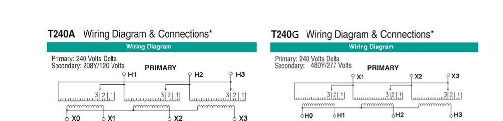
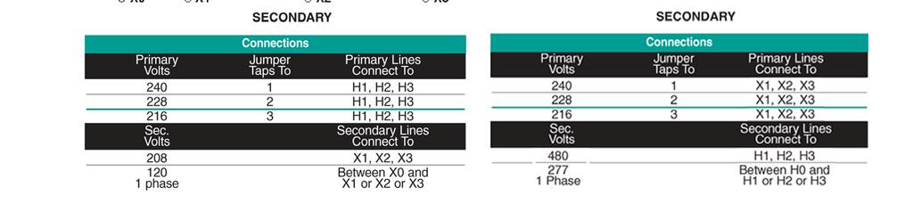
29 Sec04_2_12_09_cci.qxd:Sec04 3/25/09 2:25 PM Page 3 Three-Phase Encapsulated 4 Version JE Date Feb 09 General Purpose Three-Phase 600V Class Standard Application Voltages Encapsulated Taps: 2 5% FCBN 135 C Temperature Rise with 25 Ambient Catalog Height A Width B Depth C Wiring Est. Ship KVA Number Fig. (in.) (in.) (in.) Diagram Wgt. (lbs.) Y/ T208A T208H Y/ T240A T240A T240A T240A T208A T240A T240A T240A Y/ T480A T480A T480A T480A T240A T480A T480A T480A Y/ T480B T480B T480B T240G T480B T480B T480B Y/ T480C T480C T480C T480C T480A T480C T480C T480C T600A T600A T600A T600A T480B T600A T600A T600A 1050 * For units with an electrostatic shield, copper windings, and/or low temp rise requirements see suffix chart on page 4.4 LISTED Note: Housing dimensions subject to change without notice. Consult website or factory where dimensions are critical Dry-Type Transformers 4.3

30 Sec04_2_12_09_cci.qxd:Sec04 3/25/09 2:25 PM Page 4 4 Three-Phase Encapsulated General Purpose Three-Phase 600V Class Standard Application Voltages Encapsulated Taps: 2 5% FCBN 135 C Temperature Rise with 25 Ambient Catalog Height A Width B Depth C Wiring Est. Ship KVA Number Fig. (in.) (in.) (in.) Diagram Wgt. (lbs.) Y/ T208A T480C Y/ T208A T600A A T208A A A A T600E A A A * For units with an electrostatic shield, copper windings, and/or low temp rise requirements see suffix chart on page 4.4 Suffix Chart The catalog number on the standard product has a suffix of -000 To order alternate version transformers choose the suffix to match the desired features. Floor Mount (Fig 21) LISTED Electrostatic Suffix Temperature Rise Shield no shield shield no shield shield no shield shield Note: The weight, dimensions, weather shield and mounting brackets may be different than the standard (-000) version. Check our website for details Version JE Date Feb 09 NOTE: Electrostatic shields are optionally available and not shown in all wiring diagrams. * Insulate unused taps individually. 4.4 Dry-Type Transformers
31 Sec04_2_12_09_cci.qxd:Sec04 3/25/09 2:25 PM Page 5 Three-Phase Encapsulated 4 Figure 4 B C Figure 21 A T208A & * : 208 Delta Secondary: 480Y/277 PRIMARY T208H & * : 208 Delta Secondary: 208Y/120 PRIMARY SECONDARY SECONDARY Jumper Taps To Lines X1, X2, X X1, X2, X X1, X2, X3 480 H1, H2, H Phase Between H0 and H1 or H2 or H3 Jumper Taps To Lines H1, H2, H H1, H2, H H1, H2, H3 208 X1, X2, X Phase Between X0 and X1 or X2 or X3 NOTE: Electrostatic shields are optionally available and not shown in all wiring diagrams. * Insulate unused taps individually Dry-Type Transformers 4.5

32
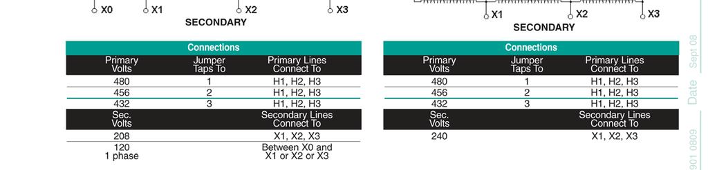
33 Sec04_2_12_09_cci.qxd:Sec04 3/25/09 2:25 PM Page 7 Three-Phase Encapsulated 4 T480C & * : 480 Delta Secondary: 480Y/277 PRIMARY T600A & * : 600 Delta Secondary: 208Y/120 PRIMARY SECONDARY Jumper Taps To Lines H1, H2, H H1, H2, H H1, H2, H3 480 X1, X2, X phase Between X0 and X1 or X2 or X3 SECONDARY Jumper Taps To Lines H1, H2, H H1, H2, H H1, H2, H3 208 X1, X2, X phase Between X0 and X1 or X2 or X3 T600E & * : 600 Delta Secondary: 240 Delta PRIMARY SECONDARY Jumper Taps To Lines H1, H2, H H1, H2, H H1, H2, H3 240 X1, X2, X3 NOTE: Electrostatic shields are optionally available and not shown in all wiring diagrams. * Insulate unused taps individually Dry-Type Transformers 4.7
34 4 Three-Phase Encapsulated Economical Auto (Open Delta) for 411 Series Three-Phase Using Two Single-Phase (Stock) Transformers For proper overcurrent protection, refer to Article of NEC High Volt Low Volt Catalog Catalog Number is for 1 transformer; KVA* Amps Amps Qty. Number 2 transformers are required 480 V Δ High V 240 V Δ Low (Open Delta) 3Ø, 60 Hz Three-Phase Using Two Single-Phase (Stock) Transformers For proper overcurrent protection, refer to Article of NEC High Volt 600 High Volt 480 High Low Low Volt 480 Low Volt 380 Volt Volt Catalog Catalog Number is for 1 transformer; KVA* KVA* Amps Amps Qty. Number 2 transformers are required 600 V Δ High 480 V Δ Low (Open Delta) 3Ø, 60 Hz 480 V Δ High 380 V Δ Low (Open Delta) 3Ø, 50/60 Hz *KVA capacity of three-phase autotransformer bank, using two single-phase, 60 Hz transformers connected in open delta. Note: Can be reverse connected with no change in KVA. Fuse input side per current NEC requirements. Refer to tables in single phase sections for dimensions and weights. 4.8 Dry-Type Transformers

35 Sec05_2_13_09_cci.qxd:Sec05 3/26/09 8:03 AM Page 1 Three-Phase Ventilated 5 Contents 15 to 1000 KVA Overview 5.2 Dimensional Drawings 5.7 s 5.8 Open Delta 5.14 Selection Charts 208 V - 208Y/120 V V - 480Y/277 V V - 208Y/120 V V - 480Y/277 V V - 208Y/120 V V V V - 480Y/277 V V - 208Y/120 V V V 5.6 Suffix Chart Dry-Type Transformers 5.1
36 Sec05_2_13_09_cci.qxd:Sec05 3/26/09 8:03 AM Page 2 5 Three-Phase Ventilated Products 150ºC Temperature Rise: 15 KVA through 1000 KVA* 80ºC and 115ºC Temperature Rise: 15 KVA through 500 KVA* Applications For general loads, indoors or out, including lighting, industrial and commercial applications Specifications Cores of high quality electrical steel Meets Federally Mandated NEMA TP-1 Standard for energy efficiency NEMA 1-rated enclosures standard Electrostatic shields optional 60 Hz operation Aluminum or copper windings Taps provided on primary 220ºC insulation class standard 150ºC, 115 C, and 80 C temperature rise Heat-cured ASA-61 gray powder coat finish Features, Functions, Benefits Designed for lower weight and smaller size for easier handling and installation Large connection compartment for ease of wiring and installation Quiet operation for installation flexibility Hassle-free front cover installation Taps provided on primary to compensate for voltage variations Standards Built in accordance with NEMA, ANSI, UL and CSA standards *Options and Accessories CE Marked units available as custom Other sizes and voltages available as custom NEMA 3R-rated enclosures available with weather shields Wall mount brackets available for units up to 75 KVA with 150ºC temperature rise 5.2 Dry-Type Transformers

37 Sec05_2_13_09_cci.qxd:Sec05 3/26/09 8:03 AM Page 3 Three-Phase Ventilated 5 Standard Construction Features This drawing is for illustration purposes only. Please consult website or factory for construction details. Fiberglass terminal board Tightly stacked electrical steel core provides lower losses and low noise Standard aluminum coils offer economical solution Front loop taps are staggered for easy connection Flexible core ground strap Ground stud bolt Vibration isolation pads provide quiet operation Side or bottom conduit access for convenient mounting options Bolt locations to hold front cover during installations loosen, don t remove Easy access mounting holes Dry-Type Transformers 5.3
38 Sec05_2_13_09_cci.qxd:Sec05 3/26/09 8:04 AM Page 4 5 Three-Phase Ventilated General Purpose Taps: 15 to 150 KVA 2@ 2.5% FCAN & 4@ 2.5% FCBN 150 C Temperature Rise 225 to 500 KVA 1@ 5% FCAN & 2@ 5% FCBN 750 to 1000 KVA No Taps Catalog Height A Width B Depth C Est. Ship Wiring Weather Shield Wall Bracket KVA Number* Fig. (in.) (in.) (in.) Wgt. (lbs.) Diagram Kit Kit 208 V - 208Y/120 V Aluminum windings* T208B T208B T208B T208B T208B T208B n/a T208B n/a T208F n/a T208F N/A n/a T208F n/a T208F Included n/a T208I T208F Included n/a 208 V - 480Y/277 V Aluminum windings* T208D T208D T208D T208D T208D T208D n/a T208D n/a T208G n/a T208G N/A n/a T208G n/a T208F Included n/a T208J T208F Included n/a 240 V - 208Y/120 V Aluminum windings* T208D T208D T8D T240B T208D T208D n/a T208D n/a T208G n/a T240F T208G N/A n/a T208G n/a T240I T208F Included n/a T208F Included n/a 240 V - 480Y/277 V Aluminum windings* T208D T208D T8D T240D T208D T208D n/a T208D n/a T208G n/a T240E T208G N/A n/a T208G n/a T208F Included n/a T240H T208F Included n/a * For units with an electrostatic shield, copper windings, and/or low temp rise requirements see suffix chart on page 5.6 Version JE Date Feb 09 LISTED Note: Housing dimensions subject to change without notice. Consult website or factory where dimensions are critical. 5.4 Dry-Type Transformers
39 Sec05_2_13_09_cci.qxd:Sec05 3/26/09 8:04 AM Page 5 Three-Phase Ventilated 5 General Purpose Taps: 15 to 500 KVA 2@ 2.5% FCAN & 4@ 2.5% FCBN 150 C Temperature Rise 750 to 1000 KVA 2@ 2.5% FCAN & 2@ 2.5% FCBN Catalog Height A Width B Depth C Est. Ship Wiring Weather Shield Wall Bracket KVA Number* Fig. (in.) (in.) (in.) Wgt. (lbs.) Diagram Kit Kit 480 V - 208Y/120 V Aluminum windings* T208B T208B T208B T208B T480E T208B n/a T208B n/a T208F n/a T208F N/A n/a T208F n/a T480M T208F Included n/a T208F Included n/a 480 V V Aluminum windings * T208D T208D T208D T208D T480G T208D n/a T208D n/a T208G n/a T208G N/A n/a T208G n/a T208F Included n/a T480N T208F Included n/a Version JE Date Feb V - 480Y/277 V Aluminum windings* T208D T208D T8D T208D T480J T208D n/a T208D n/a T208G n/a T208G N/A n/a T208G n/a T480P T208F Included n/a T208F Included n/a 600 V - 208Y/120 V Aluminum windings* T208D T208D T8D T208D T600B T208D n/a T208D n/a T208G n/a T208G N/A n/a T208G n/a T600G T208F Included n/a T208F Included n/a * For units with an electrostatic shield, copper windings, and/or low temp rise requirements see suffix chart on page V center tap on center coil on 15 KVA through 1000 KVA units. Caution: When using the 120 V center tap for single-phase applications, the single-phase load should not exceed 5% of the three-phase KVA rating. Connect the X3 high leg to the B phase per NEC (do not use X3 leg for 120 V lighting). A separate single-phase transformer should be used if the single-phase load is in excess of 5%. Fuse input side per current NEC requirements. LISTED Note: Housing dimensions subject to change without notice. Consult website or factory where dimensions are critical Dry-Type Transformers 5.5
40 Sec05_2_13_09_cci.qxd:Sec05 3/26/09 8:04 AM Page 6 5 Three-Phase Ventilated General Purpose Taps: 15 to 500 KVA 2@ 2.5% FCAN & 4@ 2.5% FCBN 150 C Temperature Rise 750 to 1000 KVA 2@ 2.5% FCAN & 2@ 2.5% FCBN Catalog Height A Width B Depth C Est. Ship Wiring Weather Shield Wall Bracket KVA Number* Fig. (in.) (in.) (in.) Wgt. (lbs.) Diagram Kit Kit 600 V V Aluminum windings* A T208B A T208B A T208B A T208B A T600D T n/a A T208B n/a A T208F n/a A T208F N/A n/a A T208F n/a A T600F T208F Included n/a A T208F Included n/a * For units with an electrostatic shield, copper windings, and/or low temp rise requirements see suffix chart on page 5.6 LISTED Suffix Chart The catalog number on the standard product has a suffix of -000 To order alternate version transformers choose the suffix to match the desired features. Electrostatic Suffix Wire Temperature Rise Shield 000 Aluminum 150 no shield 005 Aluminum 150 shield 010 Aluminum 115 no shield 015 Aluminum 115 shield 080 Aluminum 80 no shield 085 Aluminum 80 shield 800 Copper 150 no shield 805 Copper 150 shield 810 Copper 115 no shield 815 Copper 115 shield 880 Copper 80 no shield 885 Copper 80 shield Note: The weight, dimensions, weather shield and mounting brackets may be different than the standard (-000) version. Check our website for details V center tap on center coil on 15 KVA through 1000 KVA units. Caution: When using the 120 V center tap for single-phase applications, the single-phase load should not exceed 5% of the three-phase KVA rating. Connect the X3 high leg to the B phase per NEC (do not use X3 leg for 120 V lighting). A separate single-phase transformer should be used if the single-phase load is in excess of 5%. Fuse input side per current NEC requirements. Version JE Date Feb 09 Note: Housing dimensions subject to change without notice. Consult website or factory where dimensions are critical. 5.6 Dry-Type Transformers
41 Sec05_2_13_09_cci.qxd:Sec05 3/26/09 8:04 AM Page 7 Three-Phase Ventilated 5 Figure 7 Figure 8 Weather Shield Kit to Make Enclosures NEMA 3R Rated Part Width Depth w/o Depth with Shipping kva* Number (B) weather shield (C) weather shield (3R-C) weight (lbs.) *kva for 150 degree rise units, low temp or K-factor units may use next larger weathershield Version JE Date Feb 09 Mounting Brackets Part Shipping Description Number weight (lbs.) For 15 KVA unit at 150 degree C rise For 16 to 75 KVA unit at 150 degree C rise Dry-Type Transformers 5.7
42 Sec05_2_13_09_cci.qxd:Sec05 3/26/09 8:04 AM Page 8 5 T208B Three-Phase Ventilated & * : 208 Delta Secondary: 208Y/120 PRIMARY T208D & * : 208 Delta Secondary: 480Y/277 PRIMARY SECONDARY On Each Coil Jumper Taps To Lines H1, H2, H H1, H2, H H1, H2, H H1, H2, H H1, H2, H H1, H2, H H1, H2, H3 208 X1, X2, X Phase Between X0 and X1 or X2 or X3 SECONDARY On Each Coil Jumper Taps To Lines X1, X2, X X1, X2, X X1, X2, X X1, X2, X X1, X2, X X1, X2, X X1, X2, X3 480 H1, H2, H Phase Between H0 and H1 or H2 or H3 T208F & * : 208 Delta Secondary: 208Y/120 PRIMARY T208G & * : 208 Delta Secondary: 480Y/277 PRIMARY SECONDARY SECONDARY On Each Coil Jumper Taps To Lines H1, H2, H H1, H2, H H1, H2, H H1, H2, H3 208 X1, X2, X Phase Between X0 and X1 or X2 or X3 On Each Coil Jumper Taps To Lines X1, X2, X X1, X2, X X1, X2, X X1, X2, X3 480 H1, H2, H Phase Between H0 and H1 or H2 or H3 NOTE: Electrostatic shields are optionally available and not shown in all wiring diagrams. * Insulate unused taps individually. 5.8 Dry-Type Transformers
43 Sec05_2_13_09_cci.qxd:Sec05 3/26/09 8:04 AM Page 9 Three-Phase Ventilated 5 T208I & * : 208 Delta Secondary: 208Y/120 PRIMARY T208J & * : 208 Delta Secondary: 480Y/277 PRIMARY SECONDARY On Each Coil Jumper Taps To Lines H1, H2, H3 208 X1, X2, X Phase Between X0 and X1 or X2 or X3 SECONDARY On Each Coil Jumper Taps To Lines X1, X2, X3 480 H1, H2, H Phase Between H0 and H1 or H2 or H3 T240B & * : 240 Delta Secondary: 208Y/120 PRIMARY T240D & * : 240 Delta Secondary: 480Y/277 PRIMARY SECONDARY On Each Coil Jumper Taps To Lines H1, H2, H H1, H2, H H1, H2, H H1, H2, H H1, H2, H H1, H2, H H1, H2, H3 208 X1, X2, X Phase Between X0 and X1 or X2 or X3 SECONDARY On Each Coil Jumper Taps To Lines X1, X2, X X1, X2, X X1, X2, X X1, X2, X X1, X2, X X1, X2, X X1, X2, X3 480 H1, H2, H Phase Between H0 and H1 or H2 or H3 NOTE: Electrostatic shields are optionally available and not shown in all wiring diagrams. * Insulate unused taps individually Dry-Type Transformers 5.9
44 Sec05_2_13_09_cci.qxd:Sec05 3/26/09 8:04 AM Page 10 5 Three-Phase Ventilated T240E & * : 240 Delta Secondary: 480Y/277 PRIMARY T240F & * : 240 Delta Secondary: 208Y/120 PRIMARY SECONDARY On Each Coil Jumper Taps To Lines X1, X2, X X1, X2, X X1, X2, X X1, X2, X3 480 H1, H2, H Phase Between H0 and H1 or H2, or H3 SECONDARY On Each Coil Jumper Taps To Lines H1, H2, H H1, H2, H H1, H2, H H1, H2, H3 208 X1, X2, X Phase Between X0 and X1 or X2, or X3 T240H & * : 240 Delta Secondary: 480Y/277 PRIMARY T240I & * : 240 Delta Secondary: 208Y/120 PRIMARY SECONDARY On Each Coil Jumper Taps To Lines X1, X2, X3 480 H1, H2, H Phase Between H0 and H1 or H2 or H3 SECONDARY On Each Coil Jumper Taps To Lines H1, H2, H3 208 X1, X2, X Phase Between X0 and X1 or X2 or X3 Version JE Date Dec Dry-Type Transformers
45 Sec05_2_13_09_cci.qxd:Sec05 3/26/09 8:04 AM Page 11 Three-Phase Ventilated 5 T480E & * : 480 Delta Secondary: 208Y/120 PRIMARY T480G & * : 480 Delta Secondary: 240 Delta/ 120 PRIMARY SECONDARY On Each Coil Jumper Taps To Lines H1, H2, H H1, H2, H H1, H2, H H1, H2, H H1, H2, H H1, H2, H H1, H2, H3 208 X1, X2, X Phase Between X0 and X1 or X2 or X3 SECONDARY On Each Coil Jumper Taps To Lines H1, H2, H H1, H2, H H1, H2, H H1, H2, H H1, H2, H H1, H2, H H1, H2, H3 240 X1, X2, X Phase X1 and X4 or X2 and X4 T480J & * : 480 Delta Secondary: 480Y/277 PRIMARY T480M & * : 480 Delta Secondary: 208Y /120 PRIMARY Version JE Date Dec 06 SECONDARY On Each Coil Jumper Taps To Lines H1, H2, H H1, H2, H H1, H2, H H1, H2, H H1, H2, H H1, H2, H H1, H2, H3 480 X1, X2, X Phase Between X0 and X1 or X2 or X3 SECONDARY On Each Coil Jumper Taps To Lines H1, H2, H H1, H2, H H1, H2, H H1, H2, H H1, H2, H3 208 X1, X2, X Phase X1 and X4 or X2 and X Dry-Type Transformers 5.11
46 Sec05_2_13_09_cci.qxd:Sec05 3/26/09 8:04 AM Page 12 5 Three-Phase Ventilated T480N & * : 480 Delta Secondary: 240 Delta/ 120 PRIMARY T480P & * : 480 Delta Secondary: 480Y /277 PRIMARY SECONDARY On Each Coil Jumper Taps To Lines H1, H2, H H1, H2, H H1, H2, H H1, H2, H H1, H2, H3 240 X1, X2, X Phase X1 and X4 or X2 and X4 SECONDARY On Each Coil Jumper Taps To Lines H1, H2, H H1, H2, H H1, H2, H H1, H2, H H1, H2, H3 480 X1, X2, X Phase Between X0 and X1 or X2 or X3 T600B & * : 600 Secondary: 208Y/120 PRIMARY T600D & * : 600 Secondary: 240 Delta/ 120 PRIMARY SECONDARY SECONDARY On Each Coil Jumper Taps To Lines Between Lines H1, H2, H H1, H2, H H1, H2, H H1, H2, H H1, H2, H H1, H2, H H1, H2, H3 208 X1, X2, X Phase Between X0 and X1 or X2 or X3 On Each Coil Jumper Taps To Lines Between Lines H1, H2, H H1, H2, H H1, H2, H H1, H2, H H1, H2, H H1, H2, H H1, H2, H3 240 X1, X2, X Phase X1 and X4 or X2 and X4 Version JE Date Feb 09 NOTE: Electrostatic shields are optionally available and not shown in all wiring diagrams. * Insulate unused taps individually Dry-Type Transformers
47 Sec05_2_13_09_cci.qxd:Sec05 3/26/09 8:05 AM Page 13 Three-Phase Ventilated 5 T600F & * : 600 Secondary: 240 Delta/ PRIMARY 120 T600G & * : 600 Secondary: 208Y/120 PRIMARY SECONDARY On Each Coil Jumper Taps To Lines Between Lines H1, H2, H H1, H2, H H1, H2, H H1, H2, H H1, H2, H3 240 X1, X2, X Phase X1 and X4 or X2 and X4 SECONDARY On Each Coil Jumper Taps To Lines Between Lines H1, H2, H H1, H2, H H1, H2, H H1, H2, H H1, H2, H3 208 X1, X2, X Phase Between X0 and X1 or X2 or X3 Version JE Date Feb Dry-Type Transformers 5.13
48 Sec05_2_13_09_cci.qxd:Sec05 3/26/09 8:05 AM Page 14 5 Three-Phase Ventilated Economical Auto (Open Delta) for 421 Series Three-Phase Using Two Single-Phase (Stock) Transformers For proper overcurrent protection, refer to Article of NEC High Volt Low Volt Catalog Catalog Number is for 1 transformer; KVA* Amps Amps Qty. Number 2 transformers are required 480 V Δ High V 240 V Δ Low (Open Delta) 3Ø, 60 Hz Three-Phase Using Two Single-Phase (Stock) Transformers For proper overcurrent protection, refer to Article of NEC High Volt 600 High Volt 480 High Low Low Volt 480 Low Volt 380 Volt Volt Catalog Catalog Number is for 1 transformer; KVA* KVA* Amps Amps Qty. Number 2 transformers are required 600 V Δ High 480 V Δ Low (Open Delta) 3Ø, 60 Hz 480 V Δ High 380 V Δ Low (Open Delta) 3Ø, 50/60 Hz *KVA capacity of three-phase autotransformer bank, using two single-phase, 60 Hz transformers connected in open delta. Note: Can be reverse connected with no change in KVA. Fuse input side per current NEC requirements. Refer to tables in single phase sections for dimensions and weights. Version JE Date Dec Dry-Type Transformers

49 Drive Isolation 7 Contents 3 to 990 KVA Date Dec 09 Version JE Overview 7.2 Drive Selector 7.3 Dimensional Drawings 7.7 s 7.8 Selection Charts 230 V - 230Y/133 V V - 460Y/266 V V - 230Y/133 V V - 460Y/266 V V - 230Y/133 V V - 460Y/266 V Dry-Type Transformers 7.1
50 7 Drive Isolation Products Three-Phase Encapsulated: 3 KVA through 11 KVA* Three-Phase Ventilated: 14 KVA through 990 KVA* Applications For industrial and commercial applications with SCR-controlled adjustable speed motor drives, and AC adjustable frequency or DC drives Specifications Complete KVA range to cover all standard drive systems Cores of high quality electrical steel NEMA 3R-rated enclosures standard on 3 KVA through 11 KVA units NEMA 1-rated enclosures standard on 14 KVA through 990 KVA units Delta primary, wye secondary to match common power sources in most three-phase rectified circuits 3KVA through 11KVA, 135 C temp rise 14KVA through 990KVA, 150ºC temperature rise standard on 220 C insulation class units Heat-cured ASA-61 gray powder coat finish Features, Functions, Benefits Large connection compartment for ease of wiring and installation Internally braced for short circuit stress protection Low impedance for better voltage regulation Low flux density to minimize core saturation Tap arrangements provided to compensate for input voltage variation Quiet operation for installation flexibility Standards Built in accordance with NEMA, ANSI, UL and CSA standards *Options and Accessories CE Marked units available as custom 80ºC and 115ºC temperature rise available Wall mount brackets available on units up to 75 KVA and 150 C temperature rise Weathershields available on units 14 KVA through 990 KVA Copper windings available Date Dec 09 Version JE Dry-Type Transformers
51 Drive Isolation 7 Designed to withstand periodic over current loads caused by electronic motor drives. DIT applications include SCR-controlled adjustable speed motor drives, and AC adjustable frequency or DC drives Drive Selector Chart To determine the proper size drive isolation transformer, locate the HP of the motors to be operated in the left hand column. The corresponding figure in the right hand column is the recommended transformer KVA. Use the selection table to determine the drive isolation transformer catalog number. SELECTOR CHART Date Dec 09 Version JE HP KVA Dry-Type Transformers 7.3
52 Drive Isolation (DIT) 230 V Delta (Secondary 230Y/133) Taps: 1@ 5%FCAN, 1@ 5% FCBN kva Old Catalog # New Catalog # Dimensions (inches) Weight (lbs) Figure Wiring Diagram Weather Shield A (H) B (W) C (D) ACC DIT-CC N/A BCC DIT-CC N/A CCC DIT-CC N/A DCC DIT-CC N/A ECC DIT-CC FCC DIT-CC GCC DIT-CC HCC DIT-CC JCC DIT-CC KCC DIT-CC LCC DIT-CC MCC DIT-CC NCC DIT-CC PCC DIT-CC RCC DIT-CC SCC DIT-CC TCC DIT-CC UCC DIT-CC VCC DIT-CC WCC DIT-CC XCC DIT-CC Date Dec V Delta (Secondary 460Y/266) Taps: 1@ 5%FCAN, 1@ 5% FCBN kva Old Catalog # New Catalog # Dimensions (inches) Weight (lbs) Figure Wiring Diagram Weather Shield A (H) B (W) C (D) ACG DIT-CG N/A BCG DIT-CG N/A CCG DIT-CG N/A DCG DIT-CG N/A ECG DIT-CG FCG DIT-CG GCG DIT-CG HCG DIT-CG JCG DIT-CG KCG DIT-CG LCG DIT-CG MCG DIT-CG NCG DIT-CG PCG DIT-CG RCG DIT-CG SCG DIT-CG TCG DIT-CG UCG DIT-CG VCG DIT-CG WCG DIT-CG XCG DIT-CG Dry-Type Transformers 7.4
53 Drive Isolation (DIT) 460 V Delta (Secondary 230Y/133) Taps: 1@ 5%FCAN, 1@ 5% FCBN kva Old Catalog # New Catalog # Dimensions (inches) Weight (lbs) Figure Wiring Diagram Weather Shield A (H) B (W) C (D) AGC DIT-GC N/A BGC DIT-GC N/A CGC DIT-GC N/A DGC DIT-GC N/A EGC DIT-GC FGC DIT-GC GGC DIT-GC HGC DIT-GC JGC DIT-GC KGC DIT-GC LGC DIT-GC MGC DIT-GC NGC DIT-GC PGC DIT-GC RGC DIT-GC SGC DIT-GC TGC DIT-GC UGC DIT-GC VGC DIT-GC WGC DIT-GC XGC DIT-GC Date Dec V Delta (Secondary 460Y/266) Taps: 1@ 5%FCAN, 1@ 5% FCBN kva Old Catalog # New Catalog # Dimensions (inches) Weight (lbs) Figure Wiring Diagram Weather Shield A (H) B (W) C (D) AGG DIT-GG N/A BGG DIT-GG N/A CGG DIT-GG N/A DGG DIT-GG N/A EGG DIT-GG FGG DIT-GG GGG DIT-GG HGG DIT-GG JGG DIT-GG KGG DIT-GG LGG DIT-GG MGG DIT-GG NGG DIT-GG PGG DIT-GG RGG DIT-GG SGG DIT-GG TGG DIT-GG UGG DIT-GG VGG DIT-GG WGG DIT-GG XGG DIT-GG Dry-Type Transformers 7.5
54 Drive Isolation (DIT) 575 V Delta (Secondary 230Y/133) Taps: 1@ 5%FCAN, 1@ 5% FCBN kva Old Catalog # New Catalog # Dimensions (inches) Weight (lbs) Figure Wiring Diagram Weather Shield A (H) B (W) C (D) ALC DIT-LC N/A BLC DIT-LC N/A CLC DIT-LC N/A DLC DIT-LC N/A ELC DIT-LC FLC DIT-LC GLC DIT-LC HLC DIT-LC JLC DIT-LC KLC DIT-LC LLC DIT-LC MLC DIT-LC NLC DIT-LC PLC DIT-LC RLC DIT-LC SLC DIT-LC TLC DIT-LC ULC DIT-LC VLC DIT-LC WLC DIT-LC XLC DIT-LC Date Dec V Delta (Secondary 460Y/266) Taps: 1@ 5%FCAN, 1@ 5% FCBN kva Old Catalog # New Catalog # Dimensions (inches) Weight (lbs) Figure Wiring Diagram Weather Shield A (H) B (W) C (D) ALG DIT-LG N/A BLG DIT-LG N/A CLG DIT-LG N/A DLG DIT-LG N/A ELG DIT-LG FLG DIT-LG GLG DIT-LG HLG DIT-LG JLG DIT-LG KLG DIT-LG LLG DIT-LG MLG DIT-LG NLG DIT-LG PLG DIT-LG RLG DIT-LG SLG DIT-LG TLG DIT-LG ULG DIT-LG VLG DIT-LG WLG DIT-LG XLG DIT-LG Dry-Type Transformers 7.6
55

56 7 Drive Isolation Date Dec 09 NOTE: Electrostatic shields are optionally available and not shown in all wiring diagrams. individually. * Insulate unused taps Version JE Dry-Type Transformers


57 7 Drive Isolation Version JE Date Dec 09 NOTE: Electrostatic shields are optionally available and not shown in all wiring diagrams. * Insulate unused taps individually. 7.9 Dry-Type Transformers

58 Sec08_2_12_09_cci.qxd:Sec08 3/26/09 9:44 AM Page 1 Non-Linear Three-Phase Jefferson Plus 8 Contents 15 to 500 KVA Overview 8.2 Dimensional Drawings 8.7 s 8.8 Selection Charts 208 V - 208Y/120 V V - 480Y/277 V V - 208Y/120 V V - 480Y/277 V V - 208Y/120 V V - 480Y/277 V V - 208Y/120 V 8.6 Suffix Chart Dry-Type Transformers 8.1
59 Sec08_2_12_09_cci.qxd:Sec08 3/26/09 9:44 AM Page 2 8 Non-Linear Three-Phase Jefferson Plus Products 15 KVA through 500 KVA* Applications For electronic loads to meet non-linear load demands caused by modern office equipment For indoor/outdoor applications Specifications K-4, K-13, and K-20 rated units standard* Meets Federally Mandated NEMA TP-1 Standard for energy efficiency Cores of high quality electrical steel Cores designed for reduced flux densities to compensate for harmonic voltage distortion NEMA 1-rated enclosures standard Aluminum or copper windings Electrostatically shielded 220ºC insulation class standard 150ºC, 115 C, and 80 C temperature rise Heat-cured ASA-61 gray powder coat finish Features, Functions, Benefits Designed with lower weight and smaller size for easier handling and installation Large connection compartment for ease of wiring and installation Quiet operation for installation flexibility Hassle-free front cover installation Taps provided on primary to compensate for voltage variations Standards Built in accordance with NEMA, ANSI, UL and CSA standards *Options and Accessories CE Marked units available Other sizes, voltages, and connections available as custom Other K-factor rated units available as custom NEMA 3R-rated weather shields available Wall mount brackets available 8.2 Dry-Type Transformers
60 Sec08_2_12_09_cci.qxd:Sec08 3/26/09 9:44 AM Page 3 Non-Linear Three-Phase Jefferson Plus 8 Transformers for today s electronic environment These transformers are designed to meet the non-linear load demands caused by computers and other modern electronic equipment. These types of loads can cause severe overheating in distribution transformers designed to meet the needs of a pre-electronic era. The Jefferson Plus line of non-linear transformers provides safe and efficient operation in non-linear load environments. The K-factor The K-factor is a rating devised by Underwriters Laboratories to provide uniform standards for transformers designed to handle non-linear loads. The more odd-harmonic currents present, the higher the K-factor specified in sizing the transformer. To calculate the K-factor, multiply the square of the percentage of harmonic current by the square of the harmonic order and add the results. For example, if a load is 60% of the fundamental, 65% of the third harmonic, 30% of the fifth harmonic, and 35% of the seventh harmonic, the resulting K-factor would be 12.42: (.6) (.65) 2 (3) 2 + (.30) 2 (5) 2 + (.35) 2 (7) 2 = In this example, a transformer with a K-factor of 13 should be specified. The K-factor rating defines the transformer's ability to withstand odd-harmonic currents while operating within its insulation class. When the K-factor is unknown, a transformer may be selected by using the table to the right as a guide. K-FACTOR TYPE OF LOAD K-1 Resistance heating Incandescent lighting Motors Transformers Control Distribution K-4 Welders Induction heaters HID lighting Fluorescent lighting Solid state controls K-13 Telecommunications equipment Branch circuits in classrooms and healthcare facilities K-20 Mainframe computers Variable speed drives Branch circuits with exclusive loads of data processing equipment Dry-Type Transformers 8.3
61 Sec08_2_12_09_cci.qxd:Sec08 3/26/09 9:44 AM Page 4 8 Non-Linear Three-Phase Jefferson Plus Why Your Existing Transformer May Be Inadequate Traditional transformers were designed to handle the purely resistive electrical loads created mainly by standard lighting and motors. The currents drawn by these loads are sinusoidal in shape, as is the waveshape of the supply voltage. When the loads are linear and balanced as in a typical three-phase system, the neutral current flow is zero. This is because the three-phase currents are 120 degrees out of phase with each other and cancel in the neutral. The sinusoidal current waveshape is the foundation for wire-size calculations, for determining how to balance loads to reduce neutral currents, and for subsequently reducing the size of neutral conductors to reduce material costs. The Phenomenon of Odd Harmonics The switched mode power supply (SMPS) current drawn by electronic equipment bears little resemblance to the current drawn by purely resistive loads. Instead of the traditional sinusoidal waveform, SMPS current waveforms occur in sharp bursts. This irregularity of the SMPS waveform produces a non-linear load as opposed to the linear load produced by the sinusoidal waveform. Non-linear loads on the other hand, are rich in odd harmonics, which are multiples of the fundamental 60 Hertz frequency. The major components of harmonic currents in switched mode power supplies are the third and fifth harmonics. Non-linear, off-harmonic current components become additive in the neutral and can result in a neutral current as much as double the phase current, even in a balanced system. How Harmonics Affect Transformers When these odd-harmonic currents are present, winding losses increase. The I 2 R or conductor losses are higher because harmonics increase the current. Stray losses in windings also increase because of additional eddy currents circulating within the conductors. The combination of these additional losses generate excessive heat in the transformer coils. Transformer insulation systems are designed to accommodate temperature increases due to normal stray losses. However, when required to carry non-linear loads, the heat generated exceeds the designed rating, reducing the life of the transformer and creating the possibility of premature failure. De-rating is Not the Answer De-rating a traditional linear transformer to compensate for heat build-up requires higher installation costs, provides poor energy efficiency due to increased core losses, and leaves a system that will become increasingly obsolete. 8.4 Dry-Type Transformers
62 Sec08_2_12_09_cci.qxd:Sec08 3/26/09 9:44 AM Page 5 Non-Linear Three-Phase Jefferson Plus 8 K-4 Three-Phase Taps: 15 to KVA 2@ 2.5% FCAN & 4@ 2.5% FCBN 150 C Temperature Rise Electrostatic Shield 150 to 300 KVA 1@ 5% FCAN & 2@ 5% FCBN Catalog Height A Width B Depth C Est. Ship Wiring Weather Shield Wall Bracket KVA Number* Fig. (in.) (in.) (in.) Wgt. (lbs.) Diagram Kit Kit 208 V - 208Y/120 V Aluminum windings* T208B T208B T208B T208B n/a T208B n/a T208F n/a T208F N/A n/a T208F T208F n/a V - 480Y/277 V Aluminum windings* T208D T208D T208D T208D n/a T208D n/a T208G n/a T208G N/A n/a T208G T208G n/a V - 208Y/120 V Aluminum windings* T240B T240B T240B T240B n/a T240B n/a T240F n/a T240F N/A n/a T240F T240F n/a V - 480Y/277 V Aluminum windings* T240D T240D T240D T240D n/a T240D n/a T240E n/a T240E N/A T240E n/a T240E n/a V - 208Y/120 V Aluminum windings* T480E T480E T480E T480E n/a T480E n/a T480E n/a T480E N/A n/a T480E n/a * For copper and/or low temp rise K-13 or K-20 units see suffix chart on page 8.6 Note: Housing dimensions subject to change without notice. Consult website or factory where dimensions are critical. LISTED Dry-Type Transformers 8.5
63 Sec08_2_12_09_cci.qxd:Sec08 3/26/09 9:45 AM Page 6 8 Non-Linear Three-Phase Jefferson Plus K-4 Three-Phase 150 C Temperature Rise Electrostatic Shield, Taps: 2@ 2.5% FCAN & 4@ 2.5% FCBN Catalog Height A Width B Depth C Est. Ship Wiring Weather Shield Wall Bracket KVA Number* Fig. (in.) (in.) (in.) Wgt. (lbs.) Diagram Kit Kit 480 V - 480Y/277 V Aluminum windings* T480J T480J T480J T480J n/a T480J n/a T480J n/a T480J N/A n/a T480J n/a V - 208Y/120 V Aluminum windings* T600B T600B T600B T600B n/a T600B n/a T600B n/a T600B N/A n/a T600B n/a * For copper and/or low temp rise K-13 or K-20 units see suffix chart on page 8.6 Suffix Chart The catalog number on the standard Non-Linear products have a suffix of -001 for K-4, -002 for K-13, -003 for K-20. To order alternate version transformers choose the suffix to match the desired features. Suffix Wire Temperature Rise K-Factor 001 Aluminum 150 K Aluminum 115 K Aluminum 80 K Copper 150 K Copper 115 K Copper 80 K Aluminum 150 K Aluminum 115 K Aluminum 80 K Copper 150 K Copper 115 K Copper 80 K Aluminum 150 K Aluminum 115 K Aluminum 80 K Copper 150 K Copper 115 K Copper 80 K-20 Note: The weight, dimensions, weather shield and mounting brackets may be different than the standard version. Check our website for details LISTED Note: Housing dimensions subject to change without notice. Consult website or factory where dimensions are critical. 8.6 Dry-Type Transformers
64 Sec08_2_12_09_cci.qxd:Sec08 3/26/09 9:45 AM Page 7 Non-Linear Three-Phase Jefferson Plus 8 Figure 7 Figure 8 Weather Shield Kit to Make Enclosures NEMA 3R Rated Part Width Depth w/o Depth with Shipping kva* Number (B) weather shield (C) weather shield (3R-C) weight (lbs.) *kva for 150 degree rise and K-4 units Version JE Date Feb 09 Mounting Brackets Part Shipping Description Number weight (lbs.) For 15 KVA unit at 150 degree C rise For 16 to 75 KVA unit at 150 degree C rise Dry-Type Transformers 8.7
65 Sec08_2_12_09_cci.qxd:Sec08 3/26/09 9:45 AM Page 8 8 T208B Non-Linear Three-Phase Jefferson Plus & * : 208 Delta Secondary: 208Y/120 PRIMARY T208D & * : 208 Delta Secondary: 480Y/277 PRIMARY SECONDARY On Each Coil Jumper Taps To Lines H1, H2, H H1, H2, H H1, H2, H H1, H2, H H1, H2, H H1, H2, H H1, H2, H3 208 X1, X2, X Phase Between X0 and X1 or X2 or X3 SECONDARY On Each Coil Jumper Taps To Lines X1, X2, X X1, X2, X X1, X2, X X1, X2, X X1, X2, X X1, X2, X X1, X2, X3 480 H1, H2, H Phase Between H0 and H1 or H2 or H3 T208F & * : 208 Delta Secondary: 208Y/120 PRIMARY T208G & * : 208 Delta Secondary: 480Y/277 PRIMARY SECONDARY SECONDARY On Each Coil Jumper Taps To Lines H1, H2, H H1, H2, H H1, H2, H H1, H2, H3 208 X1, X2, X Phase Between X0 and X1 or X2 or X3 On Each Coil Jumper Taps To Lines X1, X2, X X1, X2, X X1, X2, X X1, X2, X3 480 H1, H2, H Phase Between H0 and H1 or H2 or H3 Version JE Date Dec 06 NOTE: Electrostatic shields are optionally available and not shown in all wiring diagrams. * Insulate unused taps individually. 8.8 Dry-Type Transformers
66 Sec08_2_12_09_cci.qxd:Sec08 3/26/09 9:45 AM Page 9 Non-Linear Three-Phase Jefferson Plus 8 T240B & * : 240 Delta Secondary: 208Y/120 PRIMARY T240D & * : 240 Delta Secondary: 480Y/277 PRIMARY SECONDARY On Each Coil Jumper Taps To Lines H1, H2, H H1, H2, H H1, H2, H H1, H2, H H1, H2, H H1, H2, H H1, H2, H3 208 X1, X2, X Phase Between X0 and X1 or X2 or X3 SECONDARY On Each Coil Jumper Taps To Lines X1, X2, X X1, X2, X X1, X2, X X1, X2, X X1, X2, X X1, X2, X X1, X2, X3 480 H1, H2, H Phase Between H0 and H1 or H2 or H3 T240E & * : 240 Delta Secondary: 480Y/277 PRIMARY T240F & * : 240 Delta Secondary: 208Y/120 PRIMARY SECONDARY SECONDARY Version JE Date Dec 06 On Each Coil Jumper Taps To Lines X1, X2, X X1, X2, X X1, X2, X X1, X2, X3 480 H1, H2, H Phase Between H0 and H1 or H2, or H3 On Each Coil Jumper Taps To Lines H1, H2, H H1, H2, H H1, H2, H H1, H2, H3 208 X1, X2, X Phase Between X0 and X1 or X2, or X3 NOTE: Electrostatic shields are optionally available and not shown in all wiring diagrams. * Insulate unused taps individually Dry-Type Transformers 8.9
67 Sec08_2_12_09_cci.qxd:Sec08 3/26/09 9:45 AM Page 10 8 Non-Linear Three-Phase Jefferson Plus T480E & * : 480 Delta Secondary: 208Y/120 PRIMARY T480J & * : 480 Delta Secondary: 480Y/277 PRIMARY SECONDARY On Each Coil Jumper Taps To Lines H1, H2, H H1, H2, H H1, H2, H H1, H2, H H1, H2, H H1, H2, H H1, H2, H3 208 X1, X2, X Phase Between X0 and X1 or X2 or X3 SECONDARY On Each Coil Jumper Taps To Lines H1, H2, H H1, H2, H H1, H2, H H1, H2, H H1, H2, H H1, H2, H H1, H2, H3 480 X1, X2, X Phase Between X0 and X1 or X2 or X3 T600B & * : 600 Secondary: 208Y/120 PRIMARY SECONDARY On Each Coil Jumper Taps To Lines Between Lines H1, H2, H H1, H2, H H1, H2, H H1, H2, H H1, H2, H H1, H2, H H1, H2, H3 208 X1, X2, X Phase Between X0 and X1 or X2 or X3 Version JE Date Dec 06 NOTE: Electrostatic shields are optionally available and not shown in all wiring diagrams. * Insulate unused taps individually Dry-Type Transformers

68 Sec09_2_12_09_cci.qxd:Sec09 3/26/09 10:30 AM Page 1 Buck-Boost Powerformer 9 Contents to 10 KVA Overview 9.2 Dimensional Drawings 9.9 s 9.10 Selection Charts 120 x 240 V 12/24 V 60 Hz x 240 V 16/32 V 60 Hz x 480 V 24/48 V 60 Hz Dry-Type Transformers 9.1
69 Sec09_2_12_09_cci.qxd:Sec09 3/26/09 10:30 AM Page 2 9 Buck-Boost Powerformer Products Single-Phase Encapsulated: 50 VA through 10 KVA* Applications For correcting voltage line drops, landscape lighting, low voltage lighting, international voltage adaptation and motor applications Note: Buck-boost transformers do not compensate for fluctuating line voltages. Specifications Encapsulated with electrical grade resin Cores of high quality electrical steel NEMA 3R-rated enclosures 135ºC temperature rise, 180ºC insulation class or 95ºC temperature rise, 130ºC insulation class depending on kva size Heat-cured ASA-61 gray powder coat finish Features, Functions, Benefits Slotted mounting holes for quick and easy mounting Convenient wall mount design with lifting hooks above 5 KVA Permanently affixed wiring diagram Standards Built in accordance with NEMA, ANSI, UL and CSA standards *Options and Accessories CE Marked units available as custom Other sizes and voltages available as custom 9.2 Dry-Type Transformers

70 Sec09_2_12_09_cci.qxd:Sec09 3/26/09 10:30 AM Page 3 Buck-Boost Powerformer 9 Jefferson Electric single-phase Buck-Boost transformers are the most economical means available for stepping voltages up or down in many common applications. They can be used as isolating (or insulating) transformers for transforming standard line voltages to low secondary voltages. They are also used to buck or boost off-standard line voltages to satisfy standard load voltage requirements when connected in an autotransformer configuration. These transformers are designed for use on single- or three-phase circuits to supply 12/24 or 16/32 volt secondaries with 120/240 volt primary, and 24/48 volt secondaries with 240/480 volt primary. When connected in an autotransformer configuration, these small, compact and lightweight units will handle a large KVA load in comparison to their physical size and relative cost. When used as isolation transformers, they have innumerable low voltage applications. The difference between an autotransformer and an isolation transformer. In an autotransformer, the input (or primary) and the output (or secondary) are electrically connected, while in an isolation transformer they are completely separated, as shown to the right. Autotransformer Only a portion of the electrical energy is changed in an autotransformer, the remainder flowing directly between the primary and secondary. In an isolation transformer, all the energy is transformed. For these reasons, an autotransformer is smaller, lighter and less costly than a comparable isolation transformer. Isolation (or Insulating) Transformer Solve over/under line voltage problems efficiently and economically. Electrical equipment is manufactured to operate most efficiently when the line voltage is equal to or nearly equal to the nameplate rating of the equipment. A motor operated at a voltage substantially under its nameplate rating may run constantly on the starting windings, resulting in overheating and possible burn-out. The same motor operated at a voltage substantially over its nameplate rating is subject to excessive heat rise, often extending beyond the insulation temperature limits, which may eventually cause the motor to burn out. Caution: Buck-Boost transformers will not compensate for fluctuating line voltages. They should only be used when line voltage is relatively constant Dry-Type Transformers 9.3
71 Sec09_2_12_09_cci.qxd:Sec09 3/26/09 10:30 AM Page 4 9 Buck-Boost Powerformer How to Use the Buck-Boost Rapid Selector Charts: You will need the following information: Line voltage: This can be determined by measuring the supply line voltage with a voltmeter. Load voltage: The voltage at which your equipment was designed to operate. Usually listed on the equipment nameplate. Load KVA or load amps: One of these will usually be listed on the nameplate. You do not need both. Supply line and equipment frequencies: This will be either 50 or 60 cycles. The supply line frequency must be the same as the frequency of the equipment to be operated. Supply line and equipment phase: Either single-phase or three-phase. The line phase must be the same as the equipment. The type of electrical configuration: Delta or Wye. Follow These Five Easy Steps: 1. Find the appropriate single-phase, three-phase delta or three-phase wye table. 2. Read down the voltage column and find the nearest ratio of required load voltage to line voltage for the application desired. (High and low voltage may be either input or output voltage depending on the circumstances.) 3. Reading horizontally across the line beginning with your application voltage ratio, locate in one of the KVA columns a KVA capacity equal to or larger than your load requirement. 4. Note the two digit number at the top of the KVA column listing the KVA capacity you require. 5. In the catalog number column, add these two digits to the catalog number next to the voltage ratio you found in step one. Example: (Assume the following information) 1. A reasonably constant line voltage of 440 volts. 2. A required equipment voltage of 480 volts KVA load capacity needed. 4. Single-phase line and equipment. In the voltage column, 437 is closest to our line voltage of 440. The 480 high voltage meets our requirements exactly. Reading horizontally across this line, find 30.0 KVA, the closest larger KVA to our required Going to the very top of this column, take the two digit number, 81, and add it on the end of the catalog number on the same line as our high/low voltage. The catalog number , with 81 added on the end, is The listings here do not cover all the possible applications of these versatile transformers. Please call for advice or a quotation on special applications. 9.4 Dry-Type Transformers
72 Sec09_2_12_09_cci.qxd:Sec09 3/26/09 10:30 AM Page 5 Buck-Boost Powerformer 9 Single-Phase KVA Capacity of Encapsulated Powerformers Maximum load capabilities Low High Catalog Load Wiring Voltage (LV) Voltage (HV) Number Required* KVA KVA KVA KVA KVA KVA KVA KVA KVA KVA Diagram * Load required is calculated based on the low voltage as the load. KVA AMPS KVA AMPS KVA AMPS KVA AMPS KVA AMPS KVA AMPS KVA AMPS KVA AMPS KVA AMPS KVA AMPS KVA AMPS KVA AMPS KVA AMPS KVA AMPS KVA AMPS KVA AMPS KVA AMPS KVA AMPS KVA AMPS KVA AMPS KVA AMPS KVA AMPS KVA AMPS Buck-Boost 1 Buck-Boost 2 Buck-Boost 3 Buck-Boost Dry-Type Transformers 9.5
73 Sec09_2_12_09_cci.qxd:Sec09 3/26/09 10:30 AM Page 6 9 Buck-Boost Powerformer Three-Phase KVA Capacity of Encapsulated Powerformers Connected in Open-Delta Maximum load capabilities requiring two Powerformers Low High Catalog Load Wiring Voltage (LV) Voltage (HV) Number Required* KVA KVA KVA KVA KVA KVA KVA KVA KVA KVA Diagram xx KVA Amperes KVA xx Amperes KVA xx Amperes KVA xx Amperes KVA xx Amperes KVA xx Amperes KVA xx Amperes KVA xx Amperes KVA xx Amperes KVA xx Amperes KVA xx Amperes KVA xx Amperes KVA xx Amperes KVA xx Amperes KVA xx Amperes KVA xx Amperes KVA xx Amperes * Load required is calculated based on the low voltage as the load. Buck-Boost 9 Buck-Boost 10 Buck-Boost 11 Buck-Boost Dry-Type Transformers
74 Sec09_2_12_09_cci.qxd:Sec09 3/26/09 10:31 AM Page 7 Buck-Boost Powerformer 9 Three-Phase KVA Capacity of Encapsulated Powerformers Connected in Wye Maximum load capabilities requiring three Powerformers Low High Catalog Load Wiring Voltage (LV) Voltage (HV) Number Required* KVA KVA KVA KVA KVA KVA KVA KVA KVA KVA Diagram * Load required is calculated based on the low voltage as the load. KVA AMPS KVA AMPS KVA AMPS KVA AMPS KVA AMPS KVA AMPS KVA AMPS KVA AMPS KVA AMPS KVA AMPS KVA AMPS KVA AMPS KVA AMPS KVA AMPS KVA AMPS skva AMPS KVA AMPS KVA AMPS KVA AMPS KVA AMPS Buck-Boost 5 Buck-Boost Buck-Boost 7 Buck-Boost Dry-Type Transformers 9.7
75 Sec09_2_12_09_cci.qxd:Sec09 3/26/09 10:31 AM Page 8 9 Buck-Boost Powerformer Single-Phase - 600V Class KVA: 130 C Insulation Class KVA: 180 C Insulation Class Catalog Height A Width B Depth C Wiring Est. Ship KVA Number Fig. (in.) (in.) (in.) Diagram Wgt. (lbs.) 120 x 240 V 12/24 V 60 Hz S240B S240B S240B S240B S240B S240B S240B S240B S240B S240B S240B S240B S240B x 240 V 16/32 V 60 Hz S240C S240C S240C S240C S240C S240C 19.5 S240C S240C S240C S240C S240C S240C S240C x 480 V 24/48 Vs 60 Hz S240E S240E S240E S240E S480E 19.5 S480E S240E S240E S240E S240E S240E S240E Note: Housing dimensions subject to change without notice. Contact factory where dimension verification is critical. LISTED Version JE Date Feb Dry-Type Transformers
76 Sec09_2_12_09_cci.qxd:Sec09 3/26/09 10:31 AM Page 9 Buck-Boost Powerformer 9 Figure 2 Figure 3 B C B C A A Figure 4 B C A Dry-Type Transformers 9.9
77 Sec09_2_12_09_cci.qxd:Sec09 3/26/09 10:31 AM Page 10 9 Buck-Boost Powerformer S240B & * : 120 X 240 Secondary: 12/24 S240C & * : 120 X 240 Secondary: 16/32 Interconnect Lines 240 H2 to H3 H1-H4 120 H1 to H3 H2 to H4 H1-H4 Interconnect 24 X2 to X3 X1-X4 12 X1 to X3 X2 to X4 X1-X4 Interconnect Lines 240 H2 to H3 H1-H4 120 H1 to H3 H2 to H4 H1-H4 Interconnect 32 X2 to X3 X1-X4 16 X1 to X3 X2 to X4 X1-X4 S480E & * : 240 X 480 Secondary: 24/48 Interconnect Lines 480 H2 to H3 H1-H4 240 H1 to H3 H2 to H4 H1-H4 Interconnect 48 X2 to X3 X1-X4 24 X1 to X3 X2 to X4 X1-X4 NOTE: Electrostatic shields are optionally available and not shown in all wiring diagrams Dry-Type Transformers

78 Sec10IndContrl2_12_09 cci.qxd:69-78 UniCap IC.qxd 3/26/09 12:54 PM Page 1 Industrial Control 10 Contents 50 to 5000 VA Overview 10.2 Dimensional Drawings s 10.7 Fuse kits and Terminal covers 10.7 Selection Charts Group Voltages Secondary Voltages AA 220/230/240 x 440/460/ /115/ BB 240 x CC 120 x EE 550/575/ /115/ FF 208 x GG 208 x 230 x HH 230 x 460 x x II 380 x 400 x x JJ 200/208 x 220/230/240 x 440/460/480 23/24/25, 110/115/ KK 240 x x LL 208/220/230/240 x 380/400/416 x 110/120/125/130, 440/460/480 x 500/550/575/ /110/115/120, 85/91/95/ MM 220/230/240 x 440/460/ /115/120 x 220/230/ NN 240 x 347 x x Dry-Type Transformers 10.1
79 Sec10IndContrl2_12_09 cci.qxd:69-78 UniCap IC.qxd 3/26/09 12:54 PM Page 2 10 Industrial Control Products General purpose; 50 VA to 5000 VA Applications For commercial and industrial control applications including; control panels, conveyor systems, machine tool equipment, pump systems, and commercial air conditioning applications Specifications Encapsulated Cores of high-grade silicon steel 50/60 Hz operation Machine wound copper coils Phil-Slot-Hex head terminal screws For 50 VA to 100 VA Insulation Class of 105 C and Temp Rise of 55 C For 150 VA to 1000 VA Insulation Class of 130 C and Temp Rise of 80 C For 1500 VA to 5000 VA Insulation Class of 180 C and Temp Rise of 115 C Features and Benefits Slotted mounting holes for quick and easy mounting Permanently affixed wiring diagram for quick reference Secondary fuse clips standard on units with a single secondary voltage (-000 units) Terminal jumpers for quick series/parallel connections Standards Built in accordance with ANSI, UL, and cul standards UL and cul Listed Models with CE Marking are available Options and Accessories Other sizes and voltages are available Optional primary fuse clips available Finger safe terminal covers available Finger safe fuse covers available The optional primary fuse block is for a 13/32 x 1-1/2 class cc rejection fuse. The primary fuse should always be time delay, slow blow properly sized for the application. The standard secondary fuse clip is for a 13/32 x 1-1/2 midget fuse. The secondary fuse style is a matter of customer preference usually either time delay or fast acting. Version JE Date Feb Dry-Type Transformers
80 Sec10IndContrl2_12_09 cci.qxd:69-78 UniCap IC.qxd 3/26/09 12:54 PM Page 3 Industrial Control 10 Group AA VA Catalog Number Dimensions* Fig A B C D E Est. Ship Temp Insulation Secondary Terminal Weight Rise Temp. Fuse Clip Cover Fuse Block 220/230/240 x 440/460/ /115/ Included Included Included Included Included Included Included Included Included Included Included Included Included NA NA Group BB VA Catalog Number Dimensions* Fig A B C D E Est. Ship Temp Insulation Secondary Terminal Weight Rise Temp. Fuse Clip Cover Fuse Block 240 x Included Included Included Included Included Included Included Included Included NA Group CC VA Catalog Number Dimensions* Fig A B C D E Est. Ship Temp Insulation Secondary Terminal Weight Rise Temp. Fuse Clip Cover Fuse Block 120 x Included Included Included Included Included Included Included Included Included NA Note: Housing dimensions subject to change without notice. Consult website or factory where dimensions are critical. * Secondary fuse clips add 0.5" to C dimension. LISTED Dry-Type Transformers 10.3
81 Sec10IndContrl2_12_09 cci.qxd:69-78 UniCap IC.qxd 3/26/09 12:54 PM Page 4 10 Industrial Control Group EE Dimensions* Est. VA Catalog Number Ship Temp Insulation Secondary Terminal Fig A B C D E Fuse Block Weight Rise Temp. Fuse Clip Cover 550/575/ /115/ Included Included Included Included Included Included Included Included Included Included Group FF Dimensions* Est. VA Catalog Number Ship Temp Insulation Secondary Terminal Fig A B C D E Fuse Block Weight Rise Temp. Fuse Clip Cover 208 x Included Included Included Included Included Included Included Included Included Included Group GG VA Catalog Number Dimensions* Est. Ship Temp Insulation Secondary Terminal Fig A B C D E Weight Rise Temp. Fuse Clip Cover Fuse Block 208 x 230 x Included Included Included Included Included Included Included Included Included Included Included Included Included NA NA Note: Housing dimensions subject to change without notice. Consult website or factory where dimensions are critical. * Secondary fuse clips add 0.5" to C dimension Dry-Type Transformers
82 Sec10IndContrl2_12_09 cci.qxd:69-78 UniCap IC.qxd 3/26/09 12:54 PM Page 5 Industrial Control 10 Group HH VA Catalog Number Dimensions* Est. Ship Temp Insulation Secondary Terminal Fig A B C D E Weight Rise Temp. Fuse Clip Cover Fuse Block 230 x 460 x , Included Included Included NA NA Group II VA Catalog Number Dimensions* Est. Ship Temp Insulation Secondary Terminal Fig A B C D E Weight Rise Temp. Fuse Clip Cover Fuse Block 380 x 400 x x NA Group JJ VA Catalog Number Dimensions* Fig A B C D E Est. Ship Temp Insulation Secondary Terminal Weight Rise Temp. Fuse Clip Cover Fuse Block 200/208 x 220/230/240 x 440/460/480-23/24/25,110/115/ Included Included Included Included Included Included Included Included Included Note: Housing dimensions subject to change without notice. Consult website or factory where dimensions are critical. * Secondary fuse clips add 0.5" to C dimension Dry-Type Transformers 10.5
83 Sec10IndContrl2_12_09 cci.qxd:69-78 UniCap IC.qxd 3/26/09 12:54 PM Page 6 10 Industrial Control Group KK VA Catalog Number Dimensions* Est. Ship Temp Insulation Secondary Terminal Fig A B C D E Weight Rise Temp. Fuse Clip Cover Fuse Block 240 x x NA Group LL Dimensions* Est. VA Catalog Number Ship Temp Insulation Secondary Terminal Fig A B C D E Fuse Block Weight Rise Temp. Fuse Clip Cover 200 to to Included Included Included Included Included Included Included Group MM VA Catalog Number Dimensions* Fig A B C D E 220/230/240 x 440/460/ /115/120 x 220/230/240 Est. Ship Temp Insulation Secondary Terminal Weight Rise Temp. Fuse Clip Cover Fuse Block NA Note: Housing dimensions subject to change without notice. Consult website or factory where dimensions are critical. * Secondary fuse clips add 0.5" to C dimension. NA Version JE Date Feb Dry-Type Transformers
84 Sec10IndContrl2_12_09 cci.qxd:69-78 UniCap IC.qxd 3/26/09 12:54 PM Page 7 Industrial Control 10 Group NN VA Catalog Number Dimensions* Est. Ship Temp Insulation Secondary Terminal Fig A B C D E Weight Rise Temp. Fuse Clip Cover Fuse Block 240 x 347 x x NA NA Accessories Item Catalog Number Fig Estimated Shipping Weight Dimensions Fuse Kit adds about 1.38" to C dimension Fuse Covers adds about.25" to C dimension (1.65" total with fuse kit) Terminal Covers 4 term adds about.25" to C dimension Terminal Covers 6 term adds about.25" to C dimension Note: Housing dimensions subject to change without notice. Consult website or factory where dimensions are critical. * Secondary fuse clips add 0.5" to C dimension. + Catalog number includes covers for 10 transformers. Group AA & Group BB & Interconnect Lines 240/230/220 H1-H3, H2-H4 H1, H4 480/460/440 H2-H3 H1, H4 120/115/110 X2, XF Lines 480 H2-H3 H1, H4 240 H1-H3, H2-H4 H1, H4 24 X2, XF Dry-Type Transformers 10.7
85 Sec10IndContrl2_12_09 cci.qxd:69-78 UniCap IC.qxd 3/26/09 12:54 PM Page 8 10 Industrial Control Group CC & Group EE & Interconnect Lines 240 H2-H3 H1, H4 120 H1-H3, H2-H4 H1, H4 24 X2, XF Interconnect Lines 600/575/550 H1, H2 120/115/110 X2, X1 Group FF & Group GG & Lines 277 H1, H3 208 H2, H3 120 X2, XF Lines 460 H1, H4 230 H2, H4 208 H3, H4 Interconnect 115 X2, XF 10.8 Dry-Type Transformers
86 Sec10IndContrl2_12_09 cci.qxd:69-78 UniCap IC.qxd 3/26/09 12:55 PM Page 9 Industrial Industrial Control Control Group HH & Group II & 10 Lines 575 H1, H4 460 H2, H4 230 H3, H4 115 X1, X3 95 X2, X3 Lines 415 H1, H4 400 H2, H4 380 H3, H4 110 X1-X3,X2-X4 X1, X4 220 X2-X3 X1, X4 Group JJ & Group KK & Lines 480/460/440 V H1, H4 240/230/220 V H2, H4 208/200 V H3, H4 120/115/110 V X1, X3 25/24/23 V X2, X3 Note: For Groups JJ and LL read from left to right to match primary to secondary voltages. For example, on Group JJ the 200V primary can have a 115V or 24V secondary. Lines 480 V H2-H3 H1, H4 240 V H1-H3, H2-H4 H1, H4 120 V X1-X3, X2-X4 X1, X4 240 V X2-X3 X1, X Dry-Type Transformers 10.9
87 Sec10IndContrl2_12_09 cci.qxd:69-78 UniCap IC.qxd 3/26/09 12:55 PM Page Industrial Industrial Control Control Group LL & Group MM & Lines 240/230/220/208 V H2, H1 416/400/380 V H3, H1 480/460/440 V H4, H1 600/575/550/500 V H5, H1 130/125/120/110 V X4, X1 120/115/110/100 V X3, X1 99/95/91/85 V X2, X1 Lines 480/460/440 V H2-H3 H1, H4 240/230/220 V H1-H3, H2-H4 H1, H4 120/115/110 V X1-X3, X2-X4 X1, X4 240/230/220 V X2-X3 X1, X4 Group NN & Lines 380 V H1, H4 347 V H2, H4 240 V H3, H4 120 V X1-X3, X2-X4 X1, X4 240 V X2-X3 X1, X4 Note: For Groups JJ and LL read from left to right to match primary to secondary voltages. For example, on Group JJ the 200V primary can have a 115V or 24V secondary Dry-Type Transformers
88 Sec10IndContrl2_12_09 cci.qxd:69-78 UniCap IC.qxd 3/26/09 12:55 PM Page Industrial Industrial Control Control Figure 14 Figure 15 Figure 16 Figure 17 Figure 18 Figure 19 Note: Callout numbers 1 to 6 are defined in installation sheets provided with units Dry-Type Transformers 10.11
89 Sec10IndContrl2_12_09 cci.qxd:69-78 UniCap IC.qxd 3/26/09 12:55 PM Page Industrial Control Notes: Dry-Type Transformers

90 Sec11_2_13_09_cci.qxd:Sec13 3/26/09 12:20 PM Page 1 Lighting Transformers 11 Contents Pool and Spa Lighting Overview 11.2 Dimensional Drawings 11.3 s 11.3 Selection Charts 120 V - 12/13/14 V 11.3 Landscape Lighting Overview 11.4 Dimensional Drawings 11.5 s 11.5 Selection Charts 120 V - 12/13/14 V Hz for Lamp Wattages: Dry-Type Transformers 11.1
91 Sec11_2_13_09_cci.qxd:Sec13 3/26/09 12:20 PM Page 2 11 Pool and Spa Lighting Products Lamp Watts: 100 through 1000* Applications For use with submersible fixtures including swimming pools, water fountains, low voltage circuits near water or other shock hazards Note: Transformers themselves are not submersible Specifications Single-Phase encapsulated Encapsulated with electrical grade resin Cores of high quality electrical steel NEMA 3R-rated enclosures 60 Hz operation Electrostatically shielded 12, 13, 14 volt taps to compensate for voltage drop on long electrical runs Heat-cured ASA-61 gray powder coat finish Features, Functions, Benefits Resetable power circuit breakers to interrupt if a short or over-voltage occurs Quiet operation for installation flexibility Convenient wall mount design with slotted mounting holes Permanently affixed wiring diagram Standards Built in accordance with NEMA, ANSI, UL and CSA standards *Options and Accessories Other sizes and voltages available as custom 11.2 Dry-Type Transformers


92 Sec11_2_13_09_cci.qxd:Sec13 3/26/09 12:21 PM Page 3 Pool and Spa Lighting 11 Single-Phase Encapsulated For Submersible Fixtures Electrostatic Shield 60 Hz 180 C Insulation Class Lamps Catalog Height A Width B Depth C Wiring Est. Ship Watts Number Fig. (in.) (in.) (in.) Diagram Wgt. (lbs.) 120 V 12/13/14 V S120A S120A S120A S120A S120A Note: Housing dimensions subject to change without notice. Consult website or factory where dimensions are critical. Figure 2 B C S120A & * A Lines 120 H1, H2 12 ± and 12V 13 ± and 13V 14 ± and 14V NOTE: Electrostatic shields are optionally available and not shown in all wiring diagrams. * Insulate unused taps individually Dry-Type Transformers 11.3
93 Sec11_2_13_09_cci.qxd:Sec13 3/26/09 12:21 PM Page 4 11 Landscape Lighting Products Lamp Watts: 300 through 1800* Applications For outdoor landscape lighting applications Modular units support optional photocell and timer Specifications voltage 120V; Secondary voltage 12/13/14/15V One magnetic breaker per 300W circuit Electrostaticlly shielded 6 foot outdoor rated UL listed power cord Features, Functions, Benefits Outdoor rated NEMA 3R enclosure with removable hinged door Removable bottom plate Black powder coat finish enclosure Stainless steel enclosure available for harsh environments Unique mounting bracket for efficient installation Ample knockouts in the bottom of the unit 1.75 inch access port in bottom of unit Finger-safe, compression-style terminal blocks each with room to accommodate four 10 gauge wires Standards Built in accordance with NEMA, ANSI, UL and CSA standards *Options and Accessories Timer Outdoor rated dial type (# TM1) External timer/photocell combination (# TM3) Photocell Button style (# PS1) Arm style (# PS2) Remote mount (# PS3) Version JE Date Feb Dry-Type Transformers

94 Sec11_2_13_09_cci.qxd:Sec13 3/26/09 12:21 PM Page 5 Landscape Lighting 11 Ratings and Dimensions Black Stainless Steel Input Current Output Power Output Dimensions in Inches Weight Amps Watts Circuits Height Width Depth* Lbs * Depth includes approximately 3/8" for the mounting bracket. Figure Dry-Type Transformers 11.5
95 Sec11_2_13_09_cci.qxd:Sec13 3/26/09 12:21 PM Page 6 11 Lighting Transformers Notes: 11.6 Dry-Type Transformers

96 Sec12_2_13_09 copy_cci.qxd:sec14 3/26/09 1:08 PM Page 1 Technical References 12 Contents Version JE Date Dec 06 Installation 12.2 Maintenance 12.3 Protective Equipment 12.4 Fuse Selection 12.5 Insulation and Temperature 12.6 Transformer Sound 12.7 Troubleshooting 12.8 Frequently Asked Questions Glossary Dry-Type Transformers 12.1
Dry Type Transformers Full Line Catalog. jeffersonelectric.com
 Dry Type Transformers Full Line Catalog jeffersonelectric.com The Transformer Authority PIONEER TRANSFORMERS: Why us? Scale We produce over 100,000 transformers every year. With this high level of production
Standards. n Built in accordance with NEMA, ANSI, UL and CSA standards
 Buck-Boost 9 0 VA to 10 Applications n A comprehensive line of transformers for low voltage applications. n Economical for stepping voltages up or down n Solve over/under voltage problems efficiently n
Steps for Selecting the Proper Transformer
 SECTION I Page 4 Steps for Selecting the Proper Transformer SINGLE PASE LOADS 1. Determine electrical load A. Voltage required by load. B. Amperes or KVA capacity required by load. C. Frequency in z (cycles
GENERAL PURPOSE DRY-TYPE DISTRIBUTION TRANSFORMERS
 GENERAL PURPOSE DRY-TYPE DISTRIBUTION TRANSFORMERS Acme offers a large selection of Dry-Type Distribution Transformers. Ranging from 600 Volt and below, in both Single and Three Phase, you re sure to find
INTERNATIONAL TRANSFORMERS. Acme Electric s broad selection of CSA energy efficient transformers
 INTERNATIONAL TRANSFORMERS Acme Electric s broad selection of CSA energy efficient transformers International Transformers What is CSA C802.2 Compliant? On January 1, 2005, the Canadian Energy Efficiency
T S 15KVA 1PH 240/480 Transformer
 3804 South Street 75964-7263, TX Nacogdoches Phone: 936-569-7941 Fax: 936-560-4685 T2535173S 15KVA 1PH 240/480 Transformer Acme Electric Catalog Number Manufacturer Description Weight per unit Product
Power Quality. Answering Today s Power Challenges. Why Your Existing Transformer May Be Inadequate. How Harmonics Affect Transformers
 Power Quality 13 Answering Today s Power Challenges Jefferson Electric is continually updating its product line to remain on the forefront of transformer technology. Electrical harmonics have become a
Warehouse Stock Transformers
 Warehouse Stock s Warehouse Stock Buck-Boost Application Description and The Buck-Boost has four separate windings, two-windings in the primary and two-windings in the secondary. The unit is designed for
HPS Universal BUCK-BOOST TRANSFORMERS
 BUCK-BOOST TRANSFORMERS Single and Three Phase Potted Buck-Boost Transformers Buck-Boost Applications & Standard Specification... 80 Selecting Buck-Boost Transformers... 81 Single Phase Selection Tables...
2.1. Product Description
 .1 NEMA TP-1 Energy-Efficient Type DT-3 Contents Description NEMA TP-1 Energy-Efficient Features, Benefits and Functions........... Standards and Certifications............... Catalog Selection................
2.5. Contents Description Motor Drive Isolation Transformers... Mini Power Centers... Totally Enclosed Non-Ventilated Transformers
 .5 Transformers Distribution Transformers Three-Phase Type DT-3E Totally Enclosed Non-Ventilated Totally Enclosed Non-Ventilated Transformers Product Description Note: The following pages provide listings
S10N06P02P 2KVA 1PH 120/240V 16/32V Buck Boost Transformer. Descriptions
 3804 South Street 75964-763, TX Nacogdoches Phone: 936-569-7941 Fax: 936-560-4685 S10N06P0P KVA 1PH 10/40V 16/3V Buck Boost Transformer Eaton Corp Catalog Manufacturer Description Weight per unit Product
LVGP. Advanced transformers built for the industrial environment. Catalog: LVGP-16C-English. By Micron Power Delivery. Supersedes: LVGP-16B-English
 LVGP By Micron Power Delivery Advanced transformers built for the industrial environment Catalog: LVGP-16C-English Supersedes: LVGP-16B-English Table of Contents Low Voltage General Purpose Transformers
Full Line Product Catalog
 Full Line Product Catalog TC Table of Contents Dry-Type Distribution Transformers Transformer Questions and Answers 6-13 Enclosure Definition 13 Steps in Transformer Selection 14-17 Construction Features
2.4. Transformers. Contents Description General-Purpose Encapsulated Transformers Catalog Number Selection... Product Selection... Product Description
 General-Purpose Encapsulated Transformers.4 Type EP 3 5 Contents Description General-Purpose Encapsulated Transformers Catalog Selection................ Product Selection....................... Single-Phase..........................
2.4. Transformers. Contents Description General-Purpose Encapsulated Transformers Catalog Number Selection... Product Selection... Product Description
 General-Purpose Encapsulated.4 Type EP 3 5 Contents Description General-Purpose Encapsulated Catalog Selection................ Product Selection....................... Single-Phase..........................
Dry-Type Transformers
 Dry-Type Transformers 600 Volt Class Bulletin 7700-99 ISO 9002 Registered 1 Federal Pacific Federal Pacific History During 1987, the Electro-Mechanical Corporation acquired the dry-type transformer division
2.4. Transformers. Contents Description General-Purpose Encapsulated Transformers Catalog Number Selection... Product Selection... Product Description
 General-Purpose Encapsulated.4 Type EP 3 5 Contents Description General-Purpose Encapsulated Catalog Selection................ Product Selection....................... Single-Phase..........................
and cured to reduce hot spots and seal out moisture. The assembly shall be installed on vibration-absorbing pads.
 -156 Purpose & Industrial Control Purpose (1000 kva and Below) mounted dry-type transformers of the two-winding type, self-cooled, with ratings and voltages as indicated on the drawings. shall be manufactured
Description & Applications Questions & Answers Selection Charts Single Phase Selection Charts Three Phase...
 SECTION BUCK-BOOST TRANSFORMERS A simple and economical way to correct offstandard voltages... from 95 to 500 volts; single and three phase, in sizes up to 60 kva. Simplified buck-boost rating charts make
PANELMDP Main Distribution Panel. Descriptions Energy Efficient Transformer
 PANELMDP Main Distribution Panel Eaton Corp Catalog Number Manufacturer Description Weight per unit Product Category Descriptions Product Type PANELMDP Eaton Corp 1.0 (lbs/each) Three Phase Energy Efficient
What is a Transformer?
 What is a Transformer? Transformers are completely static electrical devices which convert alternating current from one voltage level to another. General purpose transformers are rated 600 volts and below
Transformer Questions & Answers
 Transformer Questions & Answers. What is a transformer and how does it work? A transformer is an electrical apparatus designed to convert alternating current from one voltage to another. It can be designed
Brown University Revised 2/1/2006 Facilities Design & Construction Requirements SECTION 16461C - DRY TYPE TRANSFORMERS
 SECTION 16461C - DRY TYPE TRANSFORMERS PART 1 - GENERAL 1.1 This section includes design and performance requirements for dry-type transformers rated for use on secondary distribution systems rated 600
Transformer Questions & Answers
 Transformer Questions & Answers. What is a transformer and how does it work? A transformer is an electrical apparatus designed to convert alternating current from one voltage to another. It can be designed
BUCK-BOOST TRANSFORMERS
 Where Are Buck-Boost Transformers Used? A typical buck-boost application is 120 volts in, 12 volts out for low voltage lighting or control circuitry. In most applications, this low voltage transformer
75 kva Isolation Transformer V Delta Primary Voltage - 480Y/277 Secondary Voltage - NEMA 3R
 75 kva Isolation Transformer 4160V Delta Primary Voltage 480Y/277 Secondary Voltage NEMA 3R Part #: MTISX3P4160D75KVA480Y.277N3R Page: 1 The MTISX3P4160D75KVA480Y.277N3R 4160D 3 Phase Energy Efficient
Premium 30 Energy Efficient, Low Voltage Transformers General Purpose, Harmonic Mitigating, and K-Rated
 Premium 30 Energy Efficient, Low Voltage Transformers General Purpose, Harmonic Mitigating, and K-Rated Catalog 7400CT1001 2010 Class 7400 CONTENTS Description.............................................
500 kva Dry-type Isolation Transformer V-Delta to 208Y/120V 3PH - NEMA 1/Indoor
 500 kva Dry-type Isolation Transformer - 13200V-Delta to 208Y/120V 3PH - NEMA 1/Indoor Part #: MT-DOE16-3P-13200D-500KVA-208Y.120-N1 Page: 1 The MT-DOE16-3P-13200D-500KVA-208Y.120-N1 Dry-type Isolation
GE Ventilated Dry-Type Transformers. Secondary Substation Transformers - 5 and 15kV Class
 GE Ventilated Dry-Type Transformers Secondary Substation Transformers - 5 and 15kV Class GE ventilated dry-type transformers are designed for indoor or outdoor applications in schools, hospitals, industrial
Full Line Product Catalog
 Full Line Product Catalog E L E C T R I C A L TABLE OF CONTENTS SECTION 1 SECTION 2 SECTION 3 Dry-Type Distribution Transformers Transformer Questions & Answers... 6-10 Selection Steps... 11-12 Construction
1.5 kva Single Phase Transformer - 120V Primary Voltage - 277V Secondary Voltage - NEMA 3R
 1.5 kva Single Phase Transformer 120V Primary Voltage 277V Secondary Voltage NEMA 3R Part #: MT120V1.5KVA277V Page: 1 The MT120V1.5KVA277V 120V 1 Phase Energy Efficient Transformer from Larson Electronics
80 kva Isolation Transformer - 480V AC Primary - 20V AC Secondary - NEMA 3R - Single Phase
 80 kva Isolation Transformer 480V AC Primary 20V AC Secondary NEMA 3R Single Phase Part #: MTDOE161P480V80KVA20VN3R The MTDOE161P480V80KVA20VN3R 480V AC 1 Phase Energy Efficient Isolation Transformer from
75 kva Isolation Transformer - 480V Delta Primary - 208V Delta Secondary - NEMA 3R
 75 kva Isolation Transformer 480V Delta Primary 208V Delta Secondary NEMA 3R Part #: MTDOE163P480D75KVA208DN3R Page: 1 The MTDOE163P480D75KVA208DN3R 480D 3 Phase Energy Efficient Isolation Transformer
BUCK-BOOST TRANSFORMERS
 Hammond Power Solutions Inc. Page of Buck-boost transformers represent an economical way to both raise supply voltage caused by line drop or equipment demand on the distribution system; or lower voltage
Compliant to DOE 10, CFR Part 431 (effective as of January 1 st, 2016)
") Typical Specification 1.2kV Class Energy Efficient Dry-Type Distribution Transformers Compliant to DOE 10, CFR Part 431 (effective as of January 1 st, 2016) Canada 595 Southgate Drive Guelph, Ontario N1G
Typical Specification 1.2kV Class Energy Efficient Dry-Type Distribution Transformers Compliant to DOE 10, CFR Part 431 (effective as of January 1 st, 2016) Canada 595 Southgate Drive Guelph, Ontario N1G
General Purpose Transformers
 Transformers General Purpose Transformers Standard Units 1P 480 x 240V Primary, 120/240V Secondary.25 1D1N205.50 1D1N505.75 1D1N705 1.0 1D1N001 1.5 1D1N105 2.0 1D1N002 3.0 1D1N003 5.0 1D1N005 7.5 1D1N007
10 kva Transformer - 480V Primary Voltage - 208V Secondary Voltage - Single Phase - NEMA 3R
 10 kva Transformer 480V Primary Voltage 208V Secondary Voltage Single Phase NEMA 3R Part #: MTATX1P480V10KVA208VN3R Page: 1 The MTATX1P480V10KVA208VN3R 480V 1 Phase Energy Efficient Encapsulated Transformer
P48G11S05P 5KVA 1PH 480V - 120/240V Mini Power Center
 3804 South Street 75964-763, TX Nacogdoches Phone: 936-569-7941 Fax: 936-560-4685 P48G11S05P 5KVA 1PH 480V - 10/40V Mini Power Center Eaton Corp Catalog Number Manufacturer Description Weight per unit
General Description & Features Selection Charts Definition of Terms... 42
 SECTION NON-LINEAR LOAD ISOLATION TRANSFORMERS Special winding techniques minimize eddy current losses. A double sized neutral handles excessive neutral currents. UL Listed for K Factor Loads 4, 1 & 20.
Liquid-Filled Transformers
 Liquid-Filled Transformers Custom Transformers at Standard Prices NIAGARA TRANSFORMER CORP. Induction Furnace Transformer Cycloconverter Rectifier Duty Transformer Arc Furnace Transformer Full Range of
500 kva Isolation Transformer - 480V Delta Primary - 400Y/231 Wye Secondary - NEMA 3R
 500 kva Isolation Transformer 480V Delta Primary 400Y/231 Wye Secondary NEMA 3R Part #: MTDOE163P480D500KVA400Y.231N3R Page: 1 The MTDOE163P480D500KVA400Y.231N3R 480 V Delta 3 Phase Energy Efficient Isolation
Load Isolation Transformers
 4 Non-Linear Load Isolation Transformers Section Special winding techniques minimize eddy current losses. A double sized neutral handles excessive neutral currents. UL Listed for K Factor Loads 4, 13 &
2.5. Transformers. Mini Power Centers. Distribution Transformers. Product Description
 Distribution.5 Contents Description Motor Drive Isolation............ Mini Power Centers Standards and Certifications............... Catalog Number Selection................ Product Selection.......................
15 kva Isolation Transformer - Single Phase - 208V Primary - 120/240V Secondary - NEMA 3R
 15 kva Isolation Transformer Single Phase 208V Primary 120/240V Secondary NEMA 3R Part #: MT20815KVA240.120 Page: 1 The MT20815KVA240.120 208V 1 Phase Energy Efficient Isolation Transformer from Larson
MGM Transformer. Vacuum Pressure Impregnated (VPI) Dry-Type Substation Transformer Specification Guide
 Dry-Type Substation Transformer Specification Guide") MGM Transformer Vacuum Pressure Impregnated (VPI) Dry-Type Substation Transformer Specification Guide MGM Transformer Company 5701 Smithway Street Commerce, CA 90040 www.mgmtransformer.com Phone: 323.726.0888
MGM Transformer Vacuum Pressure Impregnated (VPI) Dry-Type Substation Transformer Specification Guide MGM Transformer Company 5701 Smithway Street Commerce, CA 90040 www.mgmtransformer.com Phone: 323.726.0888
Product Data Bulletin
 Product Data Bulletin Application Tables and Wiring Diagrams Sorgel Buck and Boost s Bulletin No. 7414PD9301 Monroe, NC, U.S.A. (Formerly B-B2R1 10/84) SINGLE PHASE Buck and Boost transformers are insulating
5 kva Isolation Transformer - 115V Primary Voltage - 230V Secondary Voltage - Single Phase - NEMA 3R
 5 kva Isolation Transformer - 115V Primary Voltage - 230V Secondary Voltage - Single Phase - NEMA 3R Part #: MT-ISX-FP-1P-115V-5KVA-230V-N3R Page: 1 The MT-ISX-FP-1P-115V-5KVA-230V-N3R 115V 1 Phase Energy
225 kva Autotransformer - 240V Delta Primary Voltage - 220V Delta Secondary Voltage - NEMA 3R
 225 kva Autotransformer 240V Delta Primary Voltage 220V Delta Secondary Voltage NEMA 3R Part #: MTATX3P240D225KVA220DN3R Page: 1 The MTATX3P240D225KVA220DN3R 240D 3 Phase Energy Efficient Autotransformer
Drive Isolation Transformers
 Drive Isolation Transformers The Acme Drive Isolation Transformers are specifically designed to accommodate the special voltages and kva sizes unique to AC and DC motor drive applications. DRIVE ISOLATION
SINGLE PHASE BUCK & BOOST TRANSFORMERS INSTRUCTION MANUAL
 SINGLE PHASE INSTRUCTION MANUAL DIAGRAM D This manual applies to all single-phase buck & boost transformers sold by Larson Electronics. Please refer to the connection diagram on pages 4-6 for properly
7.5 kva Isolation Transformer - 460V Primary - 230V Secondary - NEMA 3R - Single Phase - 50/60 Hz
 7.5 kva Isolation Transformer 460V Primary 230V Secondary NEMA 3R Single Phase 50/60 Hz Part #: MTISX1P460V7.5KVA230VN3R50.60HZ Page: 1 The MTISX1P460V7.5KVA230VN3R50.60HZ 460V 1 Phase Energy Efficient
Non-Linear Load Transformers
 Non-Linear Load Transformers Acme s Non-Linear Load and Harmonic Mitigating Transformers protect equipment on the line and prevent damage caused by harmonic currents. Many of today s electronic devices
Acme Electric Full Line Product Catalog
 Acme Electric N85 W12545 Westbrook Crossing Menomonee Falls, WI 53051 800.334.5214 acmepowerdist.com Acme Electric Full Line Product Catalog Full Line Product Catalog Today, Actuant Electrical provides
MODEL 421 Over/Under Motor Load Monitor
 MODEL 421 Over/Under Motor Load Monitor Monitors True Motor Power (volts x current x power factor) Detects Motor Overload or Underload Operates on 120 or, Single-phase or 3-phase Built-in Trip and Restart
Low Voltage Transformers. Selection Guide
 Low Voltage Transformers Selection Guide Special Purpose Transformers Non-Ventilated Transformers For use in contaminated or dust-laden environments, indoor or outdoor. Export Model Transformers Designed
Technical Data and Specifications. Core and Coil Assemblies
 February 2007 Technical Data and Specifications -161 Typical Specifications Mini-Power Centers (3 30 kva) General Furnish and install, single-phase and three-phase general purpose individually mounted
Low Voltage Power Factor Correction Equipment Specifications Automatic, Automatic Detuned, Automatic Tuned
 Low Voltage Power Factor Correction Equipment Specifications Automatic, Automatic Detuned, Automatic Tuned Part 1 - General Scope and Product Description 1.0 This specification contains the minimum design
ULTRA-K Series 600K - he
 5 kva 500 kva ULTRA-K Series 600K - he High Efficiency K-Rated Power Conditioning Transformers Designed to be used with linear or non-linear loads. Applications: Audio / Video Recording Equipment IT Systems
Baymaster LED Luminaire High Bay for Hazardous Locations
 Class I, Division, Group A, B, C, D Class I, Zone, Group IIC Class II, Division &, Group E, F, G Zone and Group IIIC Zone Group IIIB Applications Enclosed and gasketed fixtures suitable for use in: A wide
Baymaster HL LED Luminaire High Bay for Hazardous Locations
 Class I, Division, Group A, B, C, D Class I, Zone, Group IIC Class II, Division &, Group E, F, G Zone and Group IIIC Zone Group IIIB Applications Enclosed and gasketed fixtures suitable for use in: A wide
SWF DV/DT Solutions Sinewave Filters. N52 W13670 NORTHPARK DR. MENOMONEE FALLS, WI P. (262) F. (262)
 F. (262)") SWF DV/DT Solutions Sinewave Filters N52 W13670 NORTHPARK DR. MENOMONEE FALLS, WI 53051 P. (262) 754-3883 F. (262) 754-3993 www.apqpower.com Does your application use variable frequency drives for improved
SWF DV/DT Solutions Sinewave Filters N52 W13670 NORTHPARK DR. MENOMONEE FALLS, WI 53051 P. (262) 754-3883 F. (262) 754-3993 www.apqpower.com Does your application use variable frequency drives for improved
EVLP Low Profile Hazard Gard (H.I.D.) Luminaires
 Luminaires") EVLP Low Profile (H.I.D.) Luminaires Medium and Cl. I, Div. 1, Groups B (GB suffix), C, D Cl. I, Zone 1, Groups IIB + H2 (with suffix GB), IIB, IIA Cl. II, Div. 1, Groups E, F, G; Class III Marine & Wet
EVLP Low Profile (H.I.D.) Luminaires Medium and Cl. I, Div. 1, Groups B (GB suffix), C, D Cl. I, Zone 1, Groups IIB + H2 (with suffix GB), IIB, IIA Cl. II, Div. 1, Groups E, F, G; Class III Marine & Wet
Buck-Boost Transformers
 Buck-Boost Transformers Buck Boost transformers are the ideal solution anytime a line voltage change in the 5-15% range is required in single phase or three phase applications. Proper voltage is critical
PREFACE ********************************************************** IT IS NOT INTENDED THAT THESE STANDARDS BE COPIED AND USED AS A SPECIFICATION!
 PREFACE This publication has been prepared as a guide for Architectural and Engineering (A&E) firms in the preparation of documents for the design and construction of new structures and the remodeling
CONSULTANT PROCEDURES & DESIGN GUIDELINES Liquid-Filled Utility Transformers UNIVERSITY OF MISSOURI
 GENERAL: The scope of this document is to provide instruction for the installation and testing of Medium Voltage, 3 Phase, Pad Mounted Transformers installed at the University of Missouri. Preferred transformers
DISCONNECT SWITCHES. UL Listed CSA Certified
 POWER & ACTUATION ENCLOSED DISCONNECT SWITCHES When you need an at-motor non-fused disconnect switch with superior performance, look to c3controls. Our Series E2 Enclosed Disconnects feature 3- and 4-Pole
DONGAN ELECTRIC MANUFACTURING CO.
 DONGAN ELECTRIC MANUFACTURING CO. Electric Manufacturing Co. 2987 FRANKLIN DETROIT, MI 48207 800.428.2626 313.567.8500 Spec Tech Industrial 203 Vest Ave Valley Park, MO 63088 FAX 313.567.8828 www.dongan.com
A cost effective, compact and reliable PWM drive for 1/4 through 1 HP DC applications
 A cost effective, compact and reliable PWM drive for 1/4 through 1 HP DC applications The Micro 100 Drives have been designed with a Pulse Width Modulated (PWM) regulator to produce clean DC current to
INSTALLATION, OPERATION AND MAINTENANCE GUIDE
 INSTALLATION, OPERATION AND MAINTENANCE GUIDE FOR INDOOR/OUTDOOR SINGLE PHASE ENCAPSULATED TRANSFORMERS Indoor/Outdoor Encapsulated Transformers The pictures used in this guide are only a representation
10 Hazlux Lighting US Brochure
 0 Hazlux Lighting US Brochure Area lighting Hazlux 3 series Safe, durable, and now available with LED technology for superior energy efficiency, Thomas & Betts Hazlux products are the brand specifiers
Low Pass Harmonic Filters
 Exclusive e-rated Provider PRODUCT SHEET HARMITIGATOR TM Low Pass Harmonic Filters A solution for electrical distribution systems that require stable, reliable power, characterized by unparalleled power
Variable Transformers Product Design & Engineering Data
 Variable Transformers Product Design & Engineering Data Product Design & Engineering Data Type 1010B Cutaway General Information STACO ENERGY PRODUCTS CO. is a leading manufacturer of variable transformers,
1. All electrical switches and outlets used shall be equal to Hubbell heavy duty, specification grade or equivalent quality.
 PART 1: GENERAL 1.01 Wiring Devices A. This section of the standard includes design requirements for wiring connections, including receptacles and switches to equipment specified in other sections. 1.02
Class 1 Division 2 Fluorescent Light - 4 foot 2 lamp - UV bulbs - Glass Lens
 Class 1 Division 2 Fluorescent Light - 4 foot 2 lamp - UV bulbs - Glass Lens Part #: HAL-48-2L-BL-UV Made in Texas The Larson Electronics HAL-48-2L-BL-UV Hazardous Location Ultraviolet Fluorescent Light
Description. Features and Benefits
 KA-108 The General Electric Type KA-108 Bushing Potential Device is a reliable, safe, economical voltage transforming device for the operation of instruments and relays from high-voltage circuits, 115
Energy Efficient Distribution Transformers
 Energy Efficient Distribution Transformers Established in 1917, Hammond Power Solutions Inc. (HPS), is an industry leader in magnetic transformer design and development. With our headquarters in Guelph,
Line Frequency Transformer
 Line Frequency Transformer For frequencies of 50/60 Hz, specify a Frequency Transformer. Line Line Frequency Transformers are customized to meet customer requirements, and are available in various ratings.
UBC Technical Guidelines Section Edition Medium-Voltage Transformers Page 1 of 5
 Page 1 of 5 1.0 GENERAL 1.1 Coordination Requirements.1 UBC Energy & Water Services.2 UBC Building Operations 1.2 Description.1 UBC requirements for Substation Transformers. 2.0 MATERIAL AND DESIGN REQUIREMENTS
UNIVERSITY OF MISSOURI Liquid-Filled Utility Transformers 2016 Q1
 GENERAL: The scope of this document is to provide instruction for the installation and testing of Medium Voltage, 3 Phase, Pad Mounted Transformers installed at the University of Missouri. Preferred transformers
Ledex Tubular Linear Solenoids
 Ledex Tubular Linear Solenoids Force lbs. (newtons) 10 (.) (35.5) 6 (6.69) (17.79) 10% Duty Cycle 70W 5% Duty Cycle W 50% Duty Cycle 1W 100% Duty Cycle 7W saia-burgess Solenoids 1-00-99-9 www.saia-burgess-usa.com/ledex
Short-Circuit Current Calculations
 Basic Point-to-Point Calculation Procedure Step. Determine the transformer full load amps (F.L.A.) from either the nameplate, the following formulas or Table : Multiplier = 00 *% Z transformer Step 2.
Section 2 Outdoor Voltage Transformers
 Section 2 Outdoor Voltage Transformers GE Meter 130 Main St., Somersworth, NH 03878 USA & Canada: (800) 626-2004 Fax: (518) 869-2828; GE Worldwide: (518) 869-5555 2-1 120 V to 600 V BIL 10 kv Outdoor Voltage
Power-Sure 700. Technical Data TD158001EN. Contents
 Technical Data TD158001EN Power-Sure 700 Supersedes August 2015 Contents Description Page General description... 2 Power-Sure 700 benefits.... 2 Specifications... 3 Industry standards and certifications...
DTS ISOLATION TRANSFORMER SPECIFICATIONS
 1.1 Scope of Work: DTS ISOLATION TRANSFORMER SPECIFICATIONS The DTS transformers shall be designed to supply isolated power to sensitive computer based equipment. The DTS units will meet or exceed the
PRODUCT SPECIFICATION FOR A 15 AND 75 kva, THREE PHASE MODULAR POWER DISTRIBUTION SYSTEM WITH REGULATION AND CONDITIONING (Varian)
") PRODUCT SPECIFICATION FOR A 15 AND 75 kva, THREE PHASE MODULAR POWER DISTRIBUTION SYSTEM WITH REGULATION AND CONDITIONING (Varian) 1.0 General This specification covers the electrical characteristics and
PRODUCT SPECIFICATION FOR A 15 AND 75 kva, THREE PHASE MODULAR POWER DISTRIBUTION SYSTEM WITH REGULATION AND CONDITIONING (Varian) 1.0 General This specification covers the electrical characteristics and
Chapter 1. Applied Grounding and Bonding. Applied Grounding and Bonding 9/18/2011. Introduction. Introduction. Paul Dobrowsky Member NEC Panel 5
 Applied Grounding and Bonding Paul Dobrowsky Member NEC Panel 5 1 Introduction This presentation is a representative sample from the following Chapters of Applied Grounding and Bonding. Chapter 1, Introduction
SECTION TRANSFORMERS
 SECTION 16460 - TRANSFORMERS PART 1 - GENERAL 1.01 RELATED DOCUMENTS A. General: Drawings and general provisions of the Contract, including General and Supplementary Conditions and Specification Section
SPECIFICATION FOR HORIZONTAL AIRFLOW OUTDOOR RESISTIVE LOAD BANK
 SPECIFICATION FOR HORIZONTAL AIRFLOW OUTDOOR RESISTIVE LOAD BANK PART 1.0 GENERAL 1.1 SCOPE A. This specification contains the minimum requirements for the design, manufacture and testing of a UL listed,
Explosion Proof Page/Talk Paging Amplifier
 Industrial Communications Worldwide Explosion Proof Page/Talk Paging Amplifier Installation & Operation 7552-10 th Street. N.E. Calgary Alberta, Canada T2E W1 Ph: 403.25.3100 \ email:info@guardiantelecom.com
INSTRUCTION MANUAL. Type SWF. Sine Wave Filters 690 Volts, 50Hz
 POWER QUALITY INSTRUCTION MANUAL Type SWF Sine Wave Filters 690 Volts, 50Hz Page 2 of 24 Contents 1. Introduction & SAFETY 2. Theory of operation 3. Typical results of the Sine Wave Filters 4. Transportation,
Established 1942 Quality Service Competitive Prices Single Phase Transformers Three Phase Transformers Open frame or Enclosed Smoothing Chokes
 Established 94 Quality Service Competitive Prices Single Phase Transformers Three Phase Transformers Open frame or Enclosed Smoothing Chokes Supplies Up To 5kVA. Filter Chokes & Reactors Manufactured to
Solenoid Data Book 1425 Lake Avenue Woodstock, IL Phone: (815) Toll Free: Sales Fax: (815)
 Toll Free: Sales Fax: (815)") Solenoid Data Book publication v 01.03.001 1425 Lake Avenue Woodstock, IL 60098 Phone: (815) 334-3600 Toll Free: 800-762-0369 Sales Fax: (815) 337-1756 www.guardian-electric.com email: infoge@kelcomail.com
Solenoid Data Book publication v 01.03.001 1425 Lake Avenue Woodstock, IL 60098 Phone: (815) 334-3600 Toll Free: 800-762-0369 Sales Fax: (815) 337-1756 www.guardian-electric.com email: infoge@kelcomail.com
Explosion Proof Fluorescent Ultraviolet Light - Class 1 & 2-4' 2 lamp - Paint Booths, Rigs, Marine
 Explosion Proof Fluorescent Ultraviolet Light - Class 1 & 2-4' 2 lamp - Paint Booths, Rigs, Marine Part #: EPL-48-2L-UV Made in the USA The Larson Electronics EPL-48-2L-UV Explosion Proof UV Fluorescent
FLUORESCENT/AREA: NEC/CEC EXPLOSIONPROOF. Applications. Illustrated Features
 Applications Ideal for use in chemical and petrochemical plants, such as manufacturers of plastics, paints and thinners; in refineries; and in other process areas where ignitable vapors, dust, moisture
Challenges of Parallel Operations
 GENLINK TM issimilar Pitch Limiter Key Features Inserts >40% impedance in neutral current circulating path Reduces neutral circulating current by >75% Adds
Straight Isolation - Hard Wired (169 Series)
") LINE ISOLATION TRANSFORMERS (115V to 115V) Primary 115C, 60 Hz., Secondary 115C Electrostatic shield between primary & secondary Connection by flexible leads, 8" minimum length Perfect for circuit isolation
LINE ISOLATION TRANSFORMERS (115V to 115V) Primary 115C, 60 Hz., Secondary 115C Electrostatic shield between primary & secondary Connection by flexible leads, 8" minimum length Perfect for circuit isolation
High Frequency Sinewave Guardian TM Filter
 High Frequency Sinewave Guardian TM Filter 380V 480V TECHNICAL REFERENCE MANUAL FORM: SHF-TRM-E REL. April 2015 REV. 001 2015 MTE Corporation Caution Prior to start up; confirm the drive operation mode
MV ELECTRICAL TRANSMISSION DESIGN AND CONSTRUCTION STANDARD. PART 1: GENERAL 1.01 Transformer
 PART 1: GENERAL 1.01 Transformer A. This section includes liquid filled, pad mounted distribution transformers with primary voltage of 12kV or 4.16kV (The University will determine primary voltage), with
Power Processor - Series 700F 10KVA to 150KVA
 Power Processor - Series 700F 10KVA to 150KVA Power Conditioning and Regulation for Commercial & Industrial Equipment General Specifications PART 1 - GENERAL 1.1 DESCRIPTION This specification defines